EP4264014B1 - Method and system for estimating a depth pressure and/or permeability profile of a geological formation having a well - Google Patents
Method and system for estimating a depth pressure and/or permeability profile of a geological formation having a well Download PDFInfo
- Publication number
- EP4264014B1 EP4264014B1 EP20851342.4A EP20851342A EP4264014B1 EP 4264014 B1 EP4264014 B1 EP 4264014B1 EP 20851342 A EP20851342 A EP 20851342A EP 4264014 B1 EP4264014 B1 EP 4264014B1
- Authority
- EP
- European Patent Office
- Prior art keywords
- well
- fluid
- geological formation
- annular space
- closing phase
- Prior art date
- Legal status (The legal status is an assumption and is not a legal conclusion. Google has not performed a legal analysis and makes no representation as to the accuracy of the status listed.)
- Active
Links
Images



Classifications
-
- E—FIXED CONSTRUCTIONS
- E21—EARTH OR ROCK DRILLING; MINING
- E21B—EARTH OR ROCK DRILLING; OBTAINING OIL, GAS, WATER, SOLUBLE OR MELTABLE MATERIALS OR A SLURRY OF MINERALS FROM WELLS
- E21B49/00—Testing the nature of borehole walls; Formation testing; Methods or apparatus for obtaining samples of soil or well fluids, specially adapted to earth drilling or wells
- E21B49/008—Testing the nature of borehole walls; Formation testing; Methods or apparatus for obtaining samples of soil or well fluids, specially adapted to earth drilling or wells by injection test; by analysing pressure variations in an injection or production test, e.g. for estimating the skin factor
Definitions
- This disclosure relates to the field of geological formations studies, and relates more particularly to a method and system for estimating the depth pressure and/or permeability profile of a geological formation having a well, e.g. such as a well to be used for recovering hydrocarbons (oil, natural gas, shale gas, etc.) from said geological formation.
- a well e.g. such as a well to be used for recovering hydrocarbons (oil, natural gas, shale gas, etc.) from said geological formation.
- a well used for reaching a geological formation usually extends between a first end located towards the surface level, or "wellhead", and a second end opposed to the first end.
- a well consists in a borehole in the geological formation, with at most the first end cased, the cased portion being usually referred to as "shoe” of the well, the rest of the well not being cased and being usually referred to as “borehole” portion of the well.
- Such a configuration is usually referred to as "open-hole” configuration.
- the well After it has been drilled, and before considering incurring the costs of casing the well, the well undergoes well testing operations in order to determine if this well will be used for hydrocarbon recovery or abandoned as a dry hole.
- the well testing operations determine that the well may be used for hydrocarbon recovery, then it is cased, from the first end to the second end, in order to e.g. prevent it from closing upon itself.
- Well testing operations usually use tools that are inserted into the well in order to measure and evaluate physical properties of the geological formation along the length of the borehole portion of the well.
- the depth pressure profile and depth permeability profile of the geological formation are of interest.
- the depth pressure profile of the geological formation corresponds to the variation of the pressure of the geological formation (a.k.a. the natural pressure or pore pressure) along the length of the borehole portion of the well, i.e. the pressure of each layer of the geological formation passed through by the the borehole portion of the well.
- the depth permeability profile corresponds to the variation of the permeability of the geological formation along the length of the borehole portion of the well.
- document EP 2120068 A1 describes a solution for well testing operations.
- a tube is inserted down to the second end of the well.
- the tube defines two spaces inside the well: an inner space inside the tube, and an annular space surrounding the tube, between the outer surface of the tube and the inner surface of the well.
- the inner space and the annular space are in fluidic communication towards the second end of the well.
- the well is filled with two fluids and an interface between the two fluids is moved in the annular space, by injecting a second fluid in the inner space at the first end of the well, and by extracting a first fluid from the annular space at the first end, and vice versa.
- the fluids are circulated inside the well, from the first end to the second end via the inner space and from the second end to the first end via the annular space, and vice versa.
- the solution proposed enables to estimate physical properties of the borehole portion of the well. These estimated physical properties may be used to determine whether the well should be cased or not.
- a drawback of the solution described by document EP 2120068 A1 lies in the fact that it can be computationally demanding in some cases, because there are many different physical properties that need to be determined. Many computer simulations need to be performed in order to find an optimum set of values for the physical properties that is consistent with the measurements.
- the present disclosure aims at improving the situation.
- the present disclosure aims at overcoming at least some of the limitations of the prior art discussed above, by proposing a solution for estimating a depth pressure and/or permeability profile of a geological formation that reduces the computational complexity while maintaining accuracy.
- the present disclosure relates to a method for estimating a depth pressure and/or permeability profile of a geological formation, a well extending in the geological formation between a first end and a second end, said method comprising equipping the well with an inner tube extending between the first end of the well and towards the second end of the well, said tube defining an inner space and an annular space in fluid communication towards the second end of the well, wherein said method further comprises:
- the estimating method uses an inner tube that is inserted in the well, as in document EP 2120068 A1 .
- a well closing phase corresponds to a phase during which the well, initially filled with a first fluid at least in a bottom portion of the annular space, is progressively filled with a second fluid having a higher viscosity than the first fluid, the second fluid being injected in the inner space at the first end of the well while the first fluid is extracted from the annular space at the first end of the well.
- Each well closing phase is performed while maintaining the pressure substantially constant in the annular space at the first end of the well, and the estimating method uses different constant pressure values for the at least two well closing phases.
- Each well closing phase uses the same first and second fluids, i.e. the first fluid used has the same physical properties (density, viscosity, compressibility) during both well closing phases and the second fluid used has also the same physical properties during both well closing phases.
- the estimating method may rely only on measurements performed at the wellhead, without requiring inserting sensors at the bottom of the well.
- the measurements made can be used to estimate the depth pressure and/or permeability profile of the geological formation in the bottom portion of the well. Indeed, for each layer of the geological formation, the measurements may be used to derive a non-linear system having substantially two equations for two unknows, which can be solved with a reduced computational complexity with respect to the prior art.
- the estimating method can further comprise one or more of the following features, considered either alone or in any technically possible combination.
- the geological formation is decomposed in a plurality of layers, and estimating the depth pressure and/or permeability profile comprises, for each of the first well closing phase and the second well closing phase:
- the first constant pressure value P 1 and the second constant pressure value P 2 are such that: max P 1 P 2 / min P 1 P 2 > ⁇ wherein ⁇ is higher than or equal to 1.2, or higher than or equal to 1.5.
- the first fluid has the same density as the second fluid.
- the second fluid is a gel and/or the first fluid is water or brine.
- the estimating method comprises performing at least a third well closing phase under a third constant pressure value in the annular space at the first end of the well, said third constant pressure value being different from the first and second constant pressure values, and the depth pressure and/or permeability profile of the geological formation is estimated based on the measurements performed during the first, second and third well closing phases.
- the present disclosure relates to a computer program product comprising code instructions which, when executed by a processor, cause said processor to carry out the step, of the estimating method according to any one of the embodiments of the present disclosure, whereby the depth pressure and/or permeability profile of the geological formation is estimated based on the measurements performed during at least the first well closing phase and the second well closing phase.
- the present disclosure relates to a computer-readable storage medium comprising code instructions which, when executed by a processor, cause said processor to carry out the step, of the estimating method according to any one of the embodiments of the present disclosure, whereby the depth pressure and/or permeability profile of the geological formation is estimated based on the measurements performed during at least the first well closing phase and the second well closing phase.
- the present disclosure relates to a system for estimating a depth pressure and/or permeability profile of a geological formation, a well extending in the geological formation between a first end and a second end, said well being equipped with an inner tube extending between the first end of the well and towards the second end of the well, said tube defining an inner space and an annular space in fluid communication towards the second end of the well, wherein the system comprises means configured for implementing an estimating method according to any one of the embodiments of the present disclosure.
- the well comprises a cased portion at the first end and a borehole portion towards the second end.
- the present disclosure relates inter alia to a method and system for estimating a depth pressure and/or permeability profile of a geological formation having a well 10.
- the present disclosure relates more specifically to well testing operations, for measuring and evaluating physical properties of the geological formation in order to determine e.g. whether the well 10 can be used for hydrocarbon recovery.
- the present disclosure finds a main and preferred application in case of well 10 having an open-hole configuration.
- the present disclosure may also be applied to other configurations, including a well having a cased-hole configuration.
- the present disclosure is not limited to a specific geometric configuration for the well 10, and can be applied to wells comprising vertical, slanted or horizontal portions, or any combination thereof (provided that a tube 21 may be inserted inside the well 10)
- wells comprising vertical, slanted or horizontal portions, or any combination thereof (provided that a tube 21 may be inserted inside the well 10)
- a vertical well 10 having an open-hole configuration is considered, as a non-limitative example.
- Figure 1 represents schematically a cross-sectional view of a well 10 made in a geological formation 30 for which a depth pressure and/or permeability profile is to be estimated.
- the well 10 extends between a first end 11 located towards the surface level (or “wellhead”), and a second end 12, opposed to the first end 11 and located underground (or “well bottom”).
- a cemented casing which may comprise an internal metal cylinder, forms the internal lining of a cased portion 13 of the well 10 towards the first end 11.
- This cased portion 13 is also referred to as "shoe" of the well 10.
- This cased portion 13 is substantially seal-tight to the various fluids that can circulate in the well 10.
- the bottom of the cased portion 13 is situated at a depth z 1 .
- the depth of a given point along the well 10 corresponds to the length measured along the well 10 between said given point of the well 10 and a reference point of the well 10, for instance located towards the surface level.
- the reference point may be the first end 11 of the well 10.
- the depth considered herein is sometimes referred to as measured depth or MD in the literature.
- the depth injection flowrate profile to be estimated is a function of the depth (MD) measured along the well 10.
- the depth (MD) of a given point of the well 10 is different from the actual depth of this given point, which corresponds to the distance measured vertically between the surface level (or the sea level) and said given point of the well 10. This actual depth is sometimes referred to as true vertical depth or TVD in the literature.
- the well 10 comprises a borehole portion 14 which extends from the bottom of the cased portion 13 to the second end 12 of the well 10.
- the internal surface of the well 10 consists in the geological formation 30 itself.
- the borehole portion 14 passes through a succession of N geological layers denoted C 1 , C 2 , ..., C N .
- These geological layers are made of materials that are substantially homogeneous in their mineralogical composition.
- the first geological layer C 1 is situated under the cased portion 13 and adjacent to the latter.
- the geological layer C N is situated close to the second end 12.
- These geological layers C 1 - C N of materials are represented as horizontal around the well 10, but they can of course be arranged otherwise.
- Each geological layer C n (1 ⁇ n ⁇ N ) is delimited by a top surface and a bottom surface.
- the bottom surface of a geological layer C n corresponds to the top surface of the next geological layer C n +1 .
- the bottom surface of the last geological layer C N can be considered to be situated at the second end 12 of the well 10, which is situated at a depth z 2 (MD).
- the respective depths (MD) of the surfaces between the geological layers C 1 - C N may have been determined by known subsoil imaging techniques, notably by seismic techniques implemented before the drilling of the well 10 or by diagraphic techniques implemented during the drilling of the well 10. These techniques make it possible to be informed of the geometry of the geological layers C 1 - C N forming the subsoil.
- Each geological layer C n can be characterized by physical properties such as a permeability, a porosity or a pressure (sometimes referred to as natural pressure or pore pressure).
- the present disclosure aims at determining at least one among the pressure and the permeability for each geological layer C n (1 ⁇ n ⁇ N ) but may also be used to estimate other physical properties.
- estimating the "depth pressure profile” of the geological formation 30 we mean estimating the pressure for each geological layer C n (1 ⁇ n ⁇ N ) in the borehole portion 14 of the well 10, each geological layer having a predetermined thickness associated thereto.
- estimating the "depth permeability profile” of the geological formation 30 we mean estimating the permeability for each geological layer C n (1 ⁇ n ⁇ N ) in the borehole portion of the well 10.
- the present disclosure may also be applied by considering arbitrary layers in the borehole portion 14 of the well 10 instead of geological layers C n (1 ⁇ n ⁇ N ) .
- geological layers C n (1 ⁇ n ⁇ N ) .
- the estimated depth pressure and permeability profiles may be used to identify the adjacent layers having substantially the same physical properties and which can be considered to belong to a same geological layer.
- Figure 1 shows also components of a system 20 for estimating the depth pressure and/or permeability profile of the geological formation 30 in the borehole portion 14 of the well 10.
- the system 20 for estimating the depth pressure and/or permeability profile comprises a tube 21 inserted in the well 10, extending from the first end 11 of the well 10 to substantially the second end 12 of the well 10.
- This tube 21 defines two different spaces inside the well 10:
- the inner space 15 and the annular space 16 are in fluid communication towards the second end 12 of the well 10, such that a fluid moving downwards in the inner space 15 may arrive at the second end 12 of the well 10 where it can be injected into the annular space 16 and move upwards to the first end 11 of the well 10, and vice-versa.
- the system 20 for estimating the depth pressure and/or permeability profile comprises means for injecting fluids in the tube 21 at the first end 11 of the well 10 and means for extracting fluids from the annular space 16 at the first end 11 of the well 10.
- the system 20 comprises also means for measuring and controlling continuously, at the first end 11 of the well 10:
- the extracting means comprise a valve 220, a line 221 and a pump 222 with a tank 223 adapted for containing a first fluid 22 extracted from the annular space 16 at the first end 11 of the well 10.
- the injecting means comprise a valve 230, a line 231 and a pump 232 with a tank 233 adapted for containing a second fluid 23 to be injected in the inner space 15 at the first end 11 of the well 10.
- the measuring means comprise a flowmeter 224 in the line 221, for measuring the extraction flowrate of the first fluid 22 from the annular space 16 of the well 10, and a pressure sensor 225 for measuring the pressure in the annular space 16 at the first end 11 of the well 10.
- the measuring means comprise also a flowmeter 234 in the line 231, for measuring the injection flowrate of the second fluid 23 in the inner space 15 of the well 10, and a pressure sensor 235 for measuring the pressure in the inner space 15 at the first end 11 of the well 10.
- injecting, extracting and measuring means illustrated in figure 1 correspond to a non-limitative examplary configuration. It is emphasized that other configurations may be used, as long as they enable:
- the injecting, extracting and measuring means need to enable continuously injecting a second fluid 23 in the inner space 15 and simultaneously extracting a first fluid 22 from the annular space 16, while maintaining a constant pressure value in the annular space 16 at the first end 11 of the well 10.
- the estimating system 20 comprises also means for estimating the depth pressure and/or permeability profile of the geological formation 30 in the borehole portion of the well 10 based on the measurements performed by the measuring means.
- estimating means correspond for instance to a processing circuit comprising one or more processors and storage means (magnetic hard disk, solid-state disk, optical disk, or any type of computer-readable storage medium) in which a computer program product is stored, in the form of a set of program-code instructions to be executed in order to estimate the depth pressure and/or permeability profile.
- the processing circuit can comprise one or more programmable logic circuits (FPGA, PLD, etc.), and/or one or more specialized integrated circuits (ASIC), and/or a set of discrete electronic components, etc., adapted for implementing all or part of the operations for estimating the depth pressure and/or permeability profile of the geological formation 30.
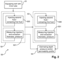
- Figure 2 represents a flow chart illustrating the main steps of a method 50 for estimating a depth pressure and/or permeability profile of the geological formation in the borehole portion 14 of the well 10.
- the estimating method 50 comprises first a step 51 of equipping the well 10 with the tube 21, as represented in figure 1 .
- the estimating method 50 comprises two main phases during which fluids are circulated inside the well 10. These main phases are referred to as "well closing phases”.
- the estimating method 50 comprises a step 52 of performing a first well closing phase which may start when the well 10, or at least the annular space 16 in the borehole portion 14 thereof, is filled with a first fluid 22.
- the step 52 of performing the first well closing phase comprises a step 520 of injecting a second fluid 23 into the inner space 15 at the first end 11 of the well 10, while extracting the first fluid from the annular space 16 at the first end 11 of the well 10.
- the second fluid 23 is injected continuously into the well 10 until the well 10 is filled with said second fluid 23, or at least the annular space 16 in the borehole portion 14 of the well 10.
- the injection / extraction is performed while maintaining the pressure constant in the annular space 16 at the first end 11 of the well 10, equal to a first constant pressure value P 1 , for the duration of the first well closing phase, or at least for the duration required to fill the annular space 16 in the borehole portion 14 of the well 10 with the second fluid 23.
- the second fluid 23 has a higher viscosity than the first fluid 22, thereby resulting in a "closing" of the borehole portion 14 of the well 10.
- the first fluid 22 is a non-viscous fluid such as water and/or brine
- the second fluid 23 is a viscous fluid such as a gel.
- the viscosity of the first fluid 22 is lower than 2 centipoises (cP, one cP being equal to one millipascal-second - mPa ⁇ s)
- the viscosity of the second fluid 23 is higher than 30 cP.
- the ratio between the viscosity of the second fluid 23 and the viscosity of the first fluid 22 is equal to or higher than thirty (30), for instance around fifty (50).
- the first fluid 22 and the second fluid 23 have the same density, in order to e.g. stabilize the interface 24 between the second fluid 23 and the first fluid 22.
- the second fluid 23 is not necessarily viscous, and the first fluid 22 and the second fluid 23 need only to have contrasted viscosities and to be immiscible.
- the step 52 of performing the first well closing phase comprises also a step 521 of measuring continuously:
- the estimating method 50 comprises also a step 53 of performing a second well closing phase which may start when the well 10, or at least the annular space 16 in the borehole portion 14 thereof, is filled with the first fluid 22.
- a well opening phase is performed between both well closing phases, in order to re-fill the well 10 with the first fluid 22, or at least the annular space 16 in the borehole portion 14 thereof.
- This may be accomplished, for instance, by injecting the first fluid 22 in the inner space 15 at the first end 11, or by circulating the fluids in the other direction, i.e. by injecting the first fluid 22 in the annular space 16 at the first end 11 while extracting the second fluid 23 from the inner space 15 at the first end 11.
- the step 53 of performing the second well closing phase comprises a step 530 of injecting the second fluid 23 into the inner space 15 at the first end 11 of the well 10, while extracting the first fluid 22 from the annular space 16 at the first end 11 of the well 10.
- the second fluid 23 is injected continuously into the well 10 until the well 10 is filled with said second fluid 23, or at least the annular space 16 in the borehole portion 14 of the well 10.
- the injection / extraction is performed while maintaining the pressure constant in the annular space 16 at the first end 11 of the well 10, equal to a second constant pressure value P 2 , for the duration of the first well closing phase, or at least for the duration required to fill the annular space 16 in the borehole portion 14 of the well 10 with the second fluid 23.
- the second constant pressure value P 2 is different from the first constant pressure value P 1 , and preferably significantly different.
- the first constant pressure value P 1 and the second constant pressure value P 2 are such that: max P 1 P 2 / min P 1 P 2 > ⁇ wherein ⁇ is higher than or equal to 1.2, or higher than or equal to 1.5, or preferably higher than or equal to 2.
- the step 53 of performing the second well closing phase comprises also a step 531 of measuring continuously:
- the estimating method 50 then comprises a step 54 of estimating the depth pressure and/or permeability profile of the geological formation 30 in the borehole portion 14 of the well 10 based on the measurements performed during the first well closing phase and the second well closing phase, i.e. the first and second temporal injection flowrates profiles, the first and second temporal extraction flowrate profiles and the first and second temporal pressure profiles.
- the first and second constant pressure values P 1 and P 2 are also used during step 54.
- Figure 3 represents schematically cross-sectional views of the well 10 during a well closing phase.
- the well 10 is assumed to be initially completely filled with the first fluid 22.
- the injection of the second fluid 23 in the inner space 15 at the first end 11 has started, and the first fluid 22 is extracted from the annular space 16 at the first end 11 while maintaining a constant pressure value ( P 1 or P 2 ) in the annular space 16 at the first end 11.
- the second fluid 23 and the first fluid 22 have different viscosities and are immiscible, such that an interface 24 between the second fluid 23 and the first fluid 22 appears inside the inner space 15 of the well 10.
- the interface 24 travels downwards inside the tube 21 from the first end 11 of the well 10 towards the second end 12 as the second fluid 23 is injected into the inner space 15 of the well 10.
- the interface 24 has reached the second end 12.
- the tube 21 is completely filled with the second fluid 23.
- the interface 24 travels upwards in the annular space 16 of the well 10, in the borehole portion 14 of the well 10. This corresponds to the actual "closing" of the well 10, since the borehole portion 14 of the well 10 is the only portion where fluids can penetrate into the geological formation 30, and since the second fluid 23 has a higher viscosity than the first fluid 22 and is therefore less likely to penetrate into the geological formation.
- the interface 24 has continued to move upwards such that the annular space 16 in the borehole portion 14 of the well 10 is completely filled with the second fluid 23.
- the interface 24 has continued to move upwards and both the inner space 15 and the annular space 16 of the well 10 are completely filled with the second fluid 23.
- Figure 4 represents schematically examples of the temporal evolution of the pressures and of the apparent injectivity (see below) obtained for the first well closing phase. More specifically, part a) of figure 4 represents the temporal evolution of the pressure P in 1 t in the inner space 15 at the first end 11 and of the pressure P out 1 t in the annular space 16 at the first end 11, and part b) of figure 4 represents the temporal evolution of the apparent injectivity q 1 ( t ) . As can be seen in part a) of figure 4 , the pressure P out 1 t remains substantially equal to the first constant pressure value P 1 during all the time interval considered.
- the pressure P in 1 t tends to decrease slightly before the first well closing phase, and then increases during the first well closing phase, especially when the second fluid 23 reaches the borehole portion 14 of the well 10, due the higher viscosity of the second fluid 23.
- the apparent injectivity q 1 ( t ) is substantially constant before the first well closing phase, and then decreases during the first well closing phase, especially when the second fluid 23 reaches the borehole portion 14 of the well 10, due the higher viscosity of the second fluid 23.
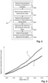
- Figure 5 represents schematically the main steps of a preferred embodiment of the estimating step 54 of the estimating method 50.
- the estimating step 54 comprises, for each of the first well closing phase and the second well closing phase:
- the estimating step 54 comprises a step 544 of determining a pressure value and/or a permeability value for each geological layer C n of the geological formation 30, based on the injectivity variation and on the reference well pressure value in the well 10 for each geological layer C n , thereby obtaining the depth pressure and/or permeability profile of the geological formation 30 in the borehole portion 14 of the well 10.
- step 540 the temporal evolution of the position in the well 10 of the interface 24 between the first fluid 22 and the second fluid 23 is determined.
- the position x j ( t ) is for instance measured from the first end 11 of the well 10, in the inner space 15, to the first end 11 of the well 10, in the annular space 16, over a length that is substantially twice the actual length of the well 10.
- the position x j ( t ) makes it possible to determine whether the interface 24 is in the inner space 15 or in the annular space 16, and more specifically whether the interface 24 is in the annular space 16 of the borehole portion 14 of the well 10.
- ⁇ q max j / q min j (in principle ⁇ is the same for both the first and second well closing phases).
- the above equations may be used to determine the temporal evolution of the position x j ( t ) of the interface 24 and the apparent injectivity q j (t) as a function of x j ( t ) during both the first well closing phase and the second well closing phase.
- figure 6 represents a graph illustrating an example of apparent injectivities determined for different positions of the interface 24 during a first well closing phase and a second closing phase.
- the borehole portion 14 of the well 10 is located between a depth z 1 (MD) of 1000 meters and a depth z 2 (MD) of 1500 meters.
- the apparent injectivity q j ( t ) decreases as the interface 24 moves upwards (from the depth z 2 to the depth z 1 ).
- the second constant pressure value P 2 is assumed to be higher than the first constant pressure value P 1 , such that the apparent injectivity q 2 ( t ) is higher than the apparent injectivity q 1 ( t ) .
- step 541 the variation of injectivity is determined for each geological layer C n .
- the variation of injectivity may be determined based on the temporal injection flowrate profile of the second fluid 23, on the temporal extraction flowrate profile of the first fluid 22 and on the temporal evolution of the position in the well 10 of the interface 24.
- the temporal evolution of the position x j ( t ) to determine an input time t in n , j and an output time t out n , j , which correspond respectively to the time when the interface 24 has entered the geological layer C n during the well closing phase of index j (i.e. first or second well closing phase) and to the time when the interface 24 has exited said geological layer C n during said well closing phase of index j.
- step 542 the temporal evolution of the pressure in the annular space 16 of the well 10, at least along the borehole portion 14, is determined.
- this step 542 aims at determining the pressure in the well 10 in a plurality of positions in the annular space 16 in the borehole portion 14, and their variations over time, denoted P well j x t , wherein:
- the well pressure P well j x t may be computed by determining the pressure losses inside the well 10, and their variations over time.
- the pressure losses may be computed e.g. by using the well-known Darcy-Weisbach equation, and depends on the considered position inside the well 10, on the characteristics of the well 10 at the considered position (e.g. dimensions and shape - e.g. disk in the inner space 15 or ring in the annular space 16 - of the cross section at the considered position), of the physical properties of the fluids (e.g. viscosity and density) and their types (Newtonian or non-Newtonian), on the current position of the interface 24, on the flowrate at the considered position (which may be obtained based on the measured injection and extraction flowrates), etc.
- the characteristics of the well 10 at the considered position e.g. dimensions and shape - e.g. disk in the inner space 15 or ring in the annular space 16 - of the cross section at the considered position
- the physical properties of the fluids e.g. viscosity and density
- their types Newtonian or non-Newtonian
- the well pressure P well j x t may be computed by using the computed pressure losses and the constant pressure value P j in the annular space 16 at the first end 11 of the well 10.
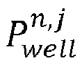
- a reference well pressure value P well n , j is determined for each geological layer C n of the geological formation 30, based on the well pressure P well j x t , in particular the well pressure values obtained for x ⁇ x j t in n , j , x j t out n , j and for t ⁇ t in n , j t out n , j .
- the reference well pressure value P well n , j may be computed as a mean value of the well pressure P well j x t over the time interval t in n , j t out n , j over the positions x j t in n , j , x j t out n , j .
- the reference well pressure value P well n , j may be computed differently.
- the estimating step 54 comprises the step 544 of determining a pressure value and/or a permeability value for each geological layer C n of the geological formation 30, based on the injectivity variations ⁇ q n,j and on the reference well pressure values P well n , j obtained for each geological layer C n and for the first and second well closing phases.
- the set of values ⁇ P geo n , 1 ⁇ n ⁇ N ⁇ corresponds to the depth pressure profile of the geological formation 30, and the set of values ⁇ k n , 1 ⁇ n ⁇ N ⁇ corresponds to the depth permeability profile of the geological formation 30.
- the well pressure at the level of the geological layer C n during the well closing phase of index j, present in ⁇ P n,j may be considered to be equal to the computed reference well pressure value P well n , j , such that ⁇ P n , j ⁇ P well n , j ⁇ P geo n .
- ⁇ q n , j F k n , P well n , j ⁇ P geo n .
- the present disclosure has been made while considering mainly two well closing phases.
- Increasing the number of well closing phases considered, and the number of different constant pressure values improves the accuracy of the estimated depth pressure and permeability profiles of the geological formation.
- increasing the number of well closing phases considered, and the number of different constant pressure values makes it possible to consider a higher number of unknowns.
- the porosity ⁇ n may be considered unknown and estimated by performing a third well closing phase, which yields a non-linear system of three equations and three unknowns.
Landscapes
- Engineering & Computer Science (AREA)
- Mining & Mineral Resources (AREA)
- Geology (AREA)
- Life Sciences & Earth Sciences (AREA)
- Fluid Mechanics (AREA)
- Environmental & Geological Engineering (AREA)
- Chemical & Material Sciences (AREA)
- Physics & Mathematics (AREA)
- Analytical Chemistry (AREA)
- General Life Sciences & Earth Sciences (AREA)
- Geochemistry & Mineralogy (AREA)
- Geophysics And Detection Of Objects (AREA)
- Investigation Of Foundation Soil And Reinforcement Of Foundation Soil By Compacting Or Drainage (AREA)
- Consolidation Of Soil By Introduction Of Solidifying Substances Into Soil (AREA)
Description
- This disclosure relates to the field of geological formations studies, and relates more particularly to a method and system for estimating the depth pressure and/or permeability profile of a geological formation having a well, e.g. such as a well to be used for recovering hydrocarbons (oil, natural gas, shale gas, etc.) from said geological formation.
- A well used for reaching a geological formation usually extends between a first end located towards the surface level, or "wellhead", and a second end opposed to the first end.
- Immediately after drilling, a well consists in a borehole in the geological formation, with at most the first end cased, the cased portion being usually referred to as "shoe" of the well, the rest of the well not being cased and being usually referred to as "borehole" portion of the well. Such a configuration is usually referred to as "open-hole" configuration.
- After it has been drilled, and before considering incurring the costs of casing the well, the well undergoes well testing operations in order to determine if this well will be used for hydrocarbon recovery or abandoned as a dry hole.
- If the well testing operations determine that the well may be used for hydrocarbon recovery, then it is cased, from the first end to the second end, in order to e.g. prevent it from closing upon itself.
- Well testing operations usually use tools that are inserted into the well in order to measure and evaluate physical properties of the geological formation along the length of the borehole portion of the well.
- In particular, the depth pressure profile and depth permeability profile of the geological formation are of interest.
- The depth pressure profile of the geological formation corresponds to the variation of the pressure of the geological formation (a.k.a. the natural pressure or pore pressure) along the length of the borehole portion of the well, i.e. the pressure of each layer of the geological formation passed through by the the borehole portion of the well. Similarly, the depth permeability profile corresponds to the variation of the permeability of the geological formation along the length of the borehole portion of the well.
- For instance, document
EP 2120068 A1 describes a solution for well testing operations. In documentEP 2120068 A1 , a tube is inserted down to the second end of the well. The tube defines two spaces inside the well: an inner space inside the tube, and an annular space surrounding the tube, between the outer surface of the tube and the inner surface of the well. The inner space and the annular space are in fluidic communication towards the second end of the well. Then the well is filled with two fluids and an interface between the two fluids is moved in the annular space, by injecting a second fluid in the inner space at the first end of the well, and by extracting a first fluid from the annular space at the first end, and vice versa. Hence, the fluids are circulated inside the well, from the first end to the second end via the inner space and from the second end to the first end via the annular space, and vice versa. By disturbing the hydraulic balance of the fluids inside the well, and by measuring effects of said disturbance of the hydraulic balance, the solution proposed enables to estimate physical properties of the borehole portion of the well. These estimated physical properties may be used to determine whether the well should be cased or not. - A drawback of the solution described by document
EP 2120068 A1 lies in the fact that it can be computationally demanding in some cases, because there are many different physical properties that need to be determined. Many computer simulations need to be performed in order to find an optimum set of values for the physical properties that is consistent with the measurements. - The documents:
- "Let's Combine Well Testing and Logging: A Pre- and Post-Frac Gas Shale Case", ANTOINE JACQUES et Al, PROCEEDINGS OF THE 7TH UNCONVENTIONAL RESOURCES TECHNOLOGY CONFERENCE, Tulsa, and
- "SPE-196116-MS Permeability Logging through Constant Pressure Injection Test: In-Situ Methodology and Laboratory Tests", Sivaprasath Manivannan et Al,
- both disclose a method for well testing.
- The present disclosure aims at improving the situation. In particular, the present disclosure aims at overcoming at least some of the limitations of the prior art discussed above, by proposing a solution for estimating a depth pressure and/or permeability profile of a geological formation that reduces the computational complexity while maintaining accuracy.
- According to a first aspect, the present disclosure relates to a method for estimating a depth pressure and/or permeability profile of a geological formation, a well extending in the geological formation between a first end and a second end, said method comprising equipping the well with an inner tube extending between the first end of the well and towards the second end of the well, said tube defining an inner space and an annular space in fluid communication towards the second end of the well, wherein said method further comprises:
- the annular space of the well being filled with a first fluid: performing a first well closing phase by injecting, into the inner space at the first end of the well, a second fluid having a higher viscosity than the first fluid while extracting, from the annular space at the first end of the well, the first fluid under a first constant pressure value in the annular space at the first end of the well, wherein the first well closing phase comprises measuring a first temporal injection flowrate profile of the second fluid, a first temporal extraction flowrate profile of the first fluid, and a first temporal pressure profile in the inner space at the first end of the well;
- the annular space of the well being filled with the first fluid: performing a second well closing phase by injecting, into the inner space at the first end of the well, the second fluid while extracting, from the annular space at the first end of the well, the first fluid under a second constant pressure value in the annular space at the first end of the well, the second constant pressure value being different from the first constant pressure value, wherein the second well closing phase comprises measuring a second temporal injection flowrate profile of the second fluid, a second temporal extraction flowrate profile of the first fluid, and a second temporal pressure profile in the inner space at the first end of the well;
- estimating the depth pressure and/or permeability profile of the geological formation based on the measurements performed during the first well closing phase and the second well closing phase.
- Hence, the estimating method uses an inner tube that is inserted in the well, as in document
EP 2120068 A1 . - Then the estimating method performs at least two well closing phases. A well closing phase corresponds to a phase during which the well, initially filled with a first fluid at least in a bottom portion of the annular space, is progressively filled with a second fluid having a higher viscosity than the first fluid, the second fluid being injected in the inner space at the first end of the well while the first fluid is extracted from the annular space at the first end of the well. Each well closing phase is performed while maintaining the pressure substantially constant in the annular space at the first end of the well, and the estimating method uses different constant pressure values for the at least two well closing phases. Each well closing phase uses the same first and second fluids, i.e. the first fluid used has the same physical properties (density, viscosity, compressibility) during both well closing phases and the second fluid used has also the same physical properties during both well closing phases.
- During each well closing phase, the injection flowrate, the extraction flowrate and the pressure in the inner space at the first end of the well are measured continuously. Hence, the estimating method may rely only on measurements performed at the wellhead, without requiring inserting sensors at the bottom of the well.
- Thanks to the fact that at least two well closing phases are performed under substantially the same conditions (same fluids used) except for the constant pressure value maintained in the annular space at the first end of the well, the measurements made can be used to estimate the depth pressure and/or permeability profile of the geological formation in the bottom portion of the well. Indeed, for each layer of the geological formation, the measurements may be used to derive a non-linear system having substantially two equations for two unknows, which can be solved with a reduced computational complexity with respect to the prior art.
- In specific embodiments, the estimating method can further comprise one or more of the following features, considered either alone or in any technically possible combination.
- In specific embodiments, the geological formation is decomposed in a plurality of layers, and estimating the depth pressure and/or permeability profile comprises, for each of the first well closing phase and the second well closing phase:
- determining a temporal evolution of the position in the well of the interface between the first fluid and the second fluid;
- determining a variation of injectivity for each layer;
- determining a temporal evolution of a pressure in the well along the layers of the geological formation;
- determining a reference well pressure value for each layer of the well based on the temporal evolution of the well pressure along the layers;
- In specific embodiments, the first constant pressure value P 1 and the second constant pressure value P 2 are such that:

- In specific embodiments, the first fluid has the same density as the second fluid.
- In specific embodiments, the second fluid is a gel and/or the first fluid is water or brine.
- In specific embodiments, the estimating method comprises performing at least a third well closing phase under a third constant pressure value in the annular space at the first end of the well, said third constant pressure value being different from the first and second constant pressure values, and the depth pressure and/or permeability profile of the geological formation is estimated based on the measurements performed during the first, second and third well closing phases.
- According to a second aspect, the present disclosure relates to a computer program product comprising code instructions which, when executed by a processor, cause said processor to carry out the step, of the estimating method according to any one of the embodiments of the present disclosure, whereby the depth pressure and/or permeability profile of the geological formation is estimated based on the measurements performed during at least the first well closing phase and the second well closing phase.
- According to a third aspect, the present disclosure relates to a computer-readable storage medium comprising code instructions which, when executed by a processor, cause said processor to carry out the step, of the estimating method according to any one of the embodiments of the present disclosure, whereby the depth pressure and/or permeability profile of the geological formation is estimated based on the measurements performed during at least the first well closing phase and the second well closing phase.
- According to a fourth aspect, the present disclosure relates to a system for estimating a depth pressure and/or permeability profile of a geological formation, a well extending in the geological formation between a first end and a second end, said well being equipped with an inner tube extending between the first end of the well and towards the second end of the well, said tube defining an inner space and an annular space in fluid communication towards the second end of the well, wherein the system comprises means configured for implementing an estimating method according to any one of the embodiments of the present disclosure.
- In specific embodiments, the well comprises a cased portion at the first end and a borehole portion towards the second end.
- The invention will be better understood upon reading the following description, given as an example that is in no way limiting, and made in reference to the figures which show:
-
Figure 1 : a schematic representation of a cross-sectional view of a well passing through a geological formation; -
Figure 2 : a flow chart illustrating the main steps of a method for estimating a depth pressure and/or permeability profile of a geological formation; -
Figure 3 : schematic representations of cross-sectional views of the well during a well closing phase of the estimating method; -
Figure 4 : graphs illustrating examples of the pressures and of the apparent injectivity obtained during a well closing phase; -
Figure 5 : a flow chart illustrating the main steps of a preferred embodiment of an estimating step of the estimating method; -
Figure 6 : graphs illustrating apparent injectivity profiles obtained for different well closing phases of the estimating method. - In these figures, references identical from one figure to another designate identical or analogous elements. For reasons of clarity, the elements shown are not to scale, unless explicitly stated otherwise.
- As discussed above, the present disclosure relates inter alia to a method and system for estimating a depth pressure and/or permeability profile of a geological formation having a well 10.
- The present disclosure relates more specifically to well testing operations, for measuring and evaluating physical properties of the geological formation in order to determine e.g. whether the well 10 can be used for hydrocarbon recovery. Hence, the present disclosure finds a main and preferred application in case of well 10 having an open-hole configuration.
- However, the present disclosure may also be applied to other configurations, including a well having a cased-hole configuration.
- Also, the present disclosure is not limited to a specific geometric configuration for the well 10, and can be applied to wells comprising vertical, slanted or horizontal portions, or any combination thereof (provided that a
tube 21 may be inserted inside the well 10)
In the following description, the case of avertical well 10 having an open-hole configuration is considered, as a non-limitative example. -
Figure 1 represents schematically a cross-sectional view of a well 10 made in ageological formation 30 for which a depth pressure and/or permeability profile is to be estimated. - As illustrated by
figure 1 , the well 10 extends between afirst end 11 located towards the surface level (or "wellhead"), and asecond end 12, opposed to thefirst end 11 and located underground (or "well bottom"). - As illustrated by
figure 1 , a cemented casing, which may comprise an internal metal cylinder, forms the internal lining of a casedportion 13 of the well 10 towards thefirst end 11. This casedportion 13 is also referred to as "shoe" of the well 10. This casedportion 13 is substantially seal-tight to the various fluids that can circulate in thewell 10. The bottom of the casedportion 13 is situated at a depth z 1. - In the present disclosure, the depth of a given point along the well 10 corresponds to the length measured along the well 10 between said given point of the well 10 and a reference point of the well 10, for instance located towards the surface level. For instance, the reference point may be the
first end 11 of the well 10. The depth considered herein is sometimes referred to as measured depth or MD in the literature. Hence, in the present disclosure, the depth injection flowrate profile to be estimated is a function of the depth (MD) measured along thewell 10. In most cases (e.g. if the well 10 is not completely vertical), the depth (MD) of a given point of the well 10 is different from the actual depth of this given point, which corresponds to the distance measured vertically between the surface level (or the sea level) and said given point of the well 10. This actual depth is sometimes referred to as true vertical depth or TVD in the literature. - Under the cased
portion 13, the well 10 comprises aborehole portion 14 which extends from the bottom of the casedportion 13 to thesecond end 12 of the well 10. In thisborehole portion 14, the internal surface of the well 10 consists in thegeological formation 30 itself. In the example illustrated byfigure 1 , theborehole portion 14 passes through a succession of N geological layers denoted C 1, C 2, ..., CN. These geological layers are made of materials that are substantially homogeneous in their mineralogical composition. The first geological layer C 1 is situated under the casedportion 13 and adjacent to the latter. The geological layer CN is situated close to thesecond end 12. These geological layers C 1-CN of materials are represented as horizontal around the well 10, but they can of course be arranged otherwise. - Each geological layer Cn (1 ≤ n ≤ N) is delimited by a top surface and a bottom surface. The bottom surface of a geological layer Cn corresponds to the top surface of the next geological layer C n+1. The bottom surface of the last geological layer CN can be considered to be situated at the
second end 12 of the well 10, which is situated at a depth z 2 (MD). - The respective depths (MD) of the surfaces between the geological layers C 1-CN may have been determined by known subsoil imaging techniques, notably by seismic techniques implemented before the drilling of the well 10 or by diagraphic techniques implemented during the drilling of the well 10. These techniques make it possible to be informed of the geometry of the geological layers C 1-CN forming the subsoil.
- Each geological layer Cn can be characterized by physical properties such as a permeability, a porosity or a pressure (sometimes referred to as natural pressure or pore pressure). The present disclosure aims at determining at least one among the pressure and the permeability for each geological layer Cn (1 ≤ n ≤ N) but may also be used to estimate other physical properties.
- By estimating the "depth pressure profile" of the
geological formation 30, we mean estimating the pressure for each geological layer Cn (1 ≤ n ≤ N) in theborehole portion 14 of the well 10, each geological layer having a predetermined thickness associated thereto. Similarly, by estimating the "depth permeability profile" of thegeological formation 30, we mean estimating the permeability for each geological layer Cn (1 ≤ n ≤ N) in the borehole portion of the well 10. - It is also emphasized that the present disclosure may also be applied by considering arbitrary layers in the
borehole portion 14 of the well 10 instead of geological layers Cn (1 ≤ n ≤ N). For instance, it is possible to consider successive layers having a same predefined thickness along the well 10, from the bottom of the casedportion 13 to thesecond end 12 of the well 10, without requiring any knowledge on the actual configuration of the geological layers Cn . In such a case, the estimated depth pressure and permeability profiles may be used to identify the adjacent layers having substantially the same physical properties and which can be considered to belong to a same geological layer. -
Figure 1 shows also components of asystem 20 for estimating the depth pressure and/or permeability profile of thegeological formation 30 in theborehole portion 14 of the well 10. - As can be seen in
figure 1 , thesystem 20 for estimating the depth pressure and/or permeability profile comprises atube 21 inserted in the well 10, extending from thefirst end 11 of the well 10 to substantially thesecond end 12 of the well 10. Thistube 21 defines two different spaces inside the well 10: - an
inner space 15 inside thetube 21; and - an
annular space 16 defined between the external surface of thetube 21 and the internal surface of the well 10 (i.e. the casing in the casedportion 13 and thegeological formation 30 itself in the borehole portion 14). - The
inner space 15 and theannular space 16 are in fluid communication towards thesecond end 12 of the well 10, such that a fluid moving downwards in theinner space 15 may arrive at thesecond end 12 of the well 10 where it can be injected into theannular space 16 and move upwards to thefirst end 11 of the well 10, and vice-versa. - The
system 20 for estimating the depth pressure and/or permeability profile comprises means for injecting fluids in thetube 21 at thefirst end 11 of the well 10 and means for extracting fluids from theannular space 16 at thefirst end 11 of the well 10. Thesystem 20 comprises also means for measuring and controlling continuously, at thefirst end 11 of the well 10: - the injection flowrate in the
inner space 15; - the extraction flowrate from the
annular space 16; - the pressure in the
inner space 15; and - the pressure in the
annular space 16. - In the non-limitative example illustrated by
figure 1 , the extracting means comprise avalve 220, aline 221 and apump 222 with atank 223 adapted for containing afirst fluid 22 extracted from theannular space 16 at thefirst end 11 of the well 10. Similarly, the injecting means comprise avalve 230, aline 231 and apump 232 with atank 233 adapted for containing asecond fluid 23 to be injected in theinner space 15 at thefirst end 11 of the well 10. - In the example illustrated by
figure 1 , the measuring means comprise aflowmeter 224 in theline 221, for measuring the extraction flowrate of the first fluid 22 from theannular space 16 of the well 10, and apressure sensor 225 for measuring the pressure in theannular space 16 at thefirst end 11 of the well 10. The measuring means comprise also aflowmeter 234 in theline 231, for measuring the injection flowrate of thesecond fluid 23 in theinner space 15 of the well 10, and apressure sensor 235 for measuring the pressure in theinner space 15 at thefirst end 11 of the well 10. - It should be noted that the injecting, extracting and measuring means illustrated in
figure 1 correspond to a non-limitative examplary configuration. It is emphasized that other configurations may be used, as long as they enable: - injecting a fluid in the
inner space 15 at thefirst end 11 of the well 10, while measuring and controlling the injection flowrate and the pressure in theinner space 15 at thefirst end 11 of the well 10; - extracting a fluid from the
annular space 16 at thefirst end 11 of the well 10, while measuring and controlling the extraction flowrate and the pressure in theannular space 16 at thefirst end 11 of the well 10. - In particular, and as will be discussed below, the injecting, extracting and measuring means need to enable continuously injecting a
second fluid 23 in theinner space 15 and simultaneously extracting a first fluid 22 from theannular space 16, while maintaining a constant pressure value in theannular space 16 at thefirst end 11 of the well 10. - The estimating
system 20 comprises also means for estimating the depth pressure and/or permeability profile of thegeological formation 30 in the borehole portion of the well 10 based on the measurements performed by the measuring means. - These estimating means (not represented in the figures) correspond for instance to a processing circuit comprising one or more processors and storage means (magnetic hard disk, solid-state disk, optical disk, or any type of computer-readable storage medium) in which a computer program product is stored, in the form of a set of program-code instructions to be executed in order to estimate the depth pressure and/or permeability profile. Alternatively, or in combination thereof, the processing circuit can comprise one or more programmable logic circuits (FPGA, PLD, etc.), and/or one or more specialized integrated circuits (ASIC), and/or a set of discrete electronic components, etc., adapted for implementing all or part of the operations for estimating the depth pressure and/or permeability profile of the
geological formation 30. -
Figure 2 represents a flow chart illustrating the main steps of amethod 50 for estimating a depth pressure and/or permeability profile of the geological formation in theborehole portion 14 of the well 10. - As illustrated by
figure 2 , the estimatingmethod 50 comprises first astep 51 of equipping the well 10 with thetube 21, as represented infigure 1 . - As illustrated by
figure 2 , the estimatingmethod 50 comprises two main phases during which fluids are circulated inside thewell 10. These main phases are referred to as "well closing phases". - The estimating
method 50 comprises astep 52 of performing a first well closing phase which may start when the well 10, or at least theannular space 16 in theborehole portion 14 thereof, is filled with afirst fluid 22. - The
step 52 of performing the first well closing phase comprises astep 520 of injecting asecond fluid 23 into theinner space 15 at thefirst end 11 of the well 10, while extracting the first fluid from theannular space 16 at thefirst end 11 of the well 10. Thesecond fluid 23 is injected continuously into the well 10 until the well 10 is filled with saidsecond fluid 23, or at least theannular space 16 in theborehole portion 14 of the well 10. - The injection / extraction is performed while maintaining the pressure constant in the
annular space 16 at thefirst end 11 of the well 10, equal to a first constant pressure value P 1, for the duration of the first well closing phase, or at least for the duration required to fill theannular space 16 in theborehole portion 14 of the well 10 with thesecond fluid 23. Thesecond fluid 23 has a higher viscosity than thefirst fluid 22, thereby resulting in a "closing" of theborehole portion 14 of the well 10. - For instance, the
first fluid 22 is a non-viscous fluid such as water and/or brine, and thesecond fluid 23 is a viscous fluid such as a gel. For instance, the viscosity of thefirst fluid 22 is lower than 2 centipoises (cP, one cP being equal to one millipascal-second - mPa·s), and the viscosity of thesecond fluid 23 is higher than 30 cP. Preferably, the ratio between the viscosity of thesecond fluid 23 and the viscosity of thefirst fluid 22 is equal to or higher than thirty (30), for instance around fifty (50). Preferably, thefirst fluid 22 and thesecond fluid 23 have the same density, in order to e.g. stabilize theinterface 24 between thesecond fluid 23 and thefirst fluid 22. However, it is emphasized that thesecond fluid 23 is not necessarily viscous, and thefirst fluid 22 and thesecond fluid 23 need only to have contrasted viscosities and to be immiscible. - The
step 52 of performing the first well closing phase comprises also astep 521 of measuring continuously: - the pressure in the
inner space 15 at thefirst end 11, thereby obtaining a first temporal pressure profile
- the injection flowrate in the
inner space 15 at thefirst end 11, thereby obtaining a first temporal injection flowrate profile
- the extraction flowrate from the
annular space 16 at thefirst end 11, thereby obtaining a first temporal extraction flowrate profile
- the pressure in the
annular space 16 at thefirst end 11, for controlling that it remains equal to the first constant pressure value P 1. - The estimating
method 50 comprises also astep 53 of performing a second well closing phase which may start when the well 10, or at least theannular space 16 in theborehole portion 14 thereof, is filled with thefirst fluid 22. - Of course, although not represented, this implies that a well opening phase is performed between both well closing phases, in order to re-fill the well 10 with the
first fluid 22, or at least theannular space 16 in theborehole portion 14 thereof. This may be accomplished, for instance, by injecting thefirst fluid 22 in theinner space 15 at thefirst end 11, or by circulating the fluids in the other direction, i.e. by injecting thefirst fluid 22 in theannular space 16 at thefirst end 11 while extracting the second fluid 23 from theinner space 15 at thefirst end 11. - The
step 53 of performing the second well closing phase comprises astep 530 of injecting thesecond fluid 23 into theinner space 15 at thefirst end 11 of the well 10, while extracting the first fluid 22 from theannular space 16 at thefirst end 11 of the well 10. Thesecond fluid 23 is injected continuously into the well 10 until the well 10 is filled with saidsecond fluid 23, or at least theannular space 16 in theborehole portion 14 of the well 10. - The injection / extraction is performed while maintaining the pressure constant in the
annular space 16 at thefirst end 11 of the well 10, equal to a second constant pressure value P 2, for the duration of the first well closing phase, or at least for the duration required to fill theannular space 16 in theborehole portion 14 of the well 10 with thesecond fluid 23. The second constant pressure value P 2 is different from the first constant pressure value P 1, and preferably significantly different. For instance, the first constant pressure value P 1 and the second constant pressure value P 2 are such that:
- The
step 53 of performing the second well closing phase comprises also astep 531 of measuring continuously: - the pressure in the
inner space 15 at thefirst end 11, thereby obtaining a second temporal pressure profile
- the injection flowrate in the
inner space 15 at thefirst end 11, thereby obtaining a second temporal injection flowrate profile
- the extraction flowrate from the
annular space 16 at thefirst end 11, thereby obtaining a second temporal extraction flowrate profile
- the pressure in the
annular space 16 at thefirst end 11, for controlling that it remains equal to the second constant pressure value P 2. - As illustrated by
figure 2 , the estimatingmethod 50 then comprises astep 54 of estimating the depth pressure and/or permeability profile of thegeological formation 30 in theborehole portion 14 of the well 10 based on the measurements performed during the first well closing phase and the second well closing phase, i.e. the first and second temporal injection flowrates profiles, the first and second temporal extraction flowrate profiles and the first and second temporal pressure profiles. The first and second constant pressure values P 1 and P 2 are also used duringstep 54. -
Figure 3 represents schematically cross-sectional views of the well 10 during a well closing phase. - In part a) of
figure 3 , the well 10 is assumed to be initially completely filled with thefirst fluid 22. In part b) offigure 3 , the injection of thesecond fluid 23 in theinner space 15 at thefirst end 11 has started, and thefirst fluid 22 is extracted from theannular space 16 at thefirst end 11 while maintaining a constant pressure value (P 1 or P 2) in theannular space 16 at thefirst end 11. Thesecond fluid 23 and thefirst fluid 22 have different viscosities and are immiscible, such that aninterface 24 between thesecond fluid 23 and thefirst fluid 22 appears inside theinner space 15 of the well 10. Theinterface 24 travels downwards inside thetube 21 from thefirst end 11 of the well 10 towards thesecond end 12 as thesecond fluid 23 is injected into theinner space 15 of the well 10. In part c) offigure 3 , theinterface 24 has reached thesecond end 12. Thetube 21 is completely filled with thesecond fluid 23. In part d) offigure 3 , theinterface 24 travels upwards in theannular space 16 of the well 10, in theborehole portion 14 of the well 10. This corresponds to the actual "closing" of the well 10, since theborehole portion 14 of the well 10 is the only portion where fluids can penetrate into thegeological formation 30, and since thesecond fluid 23 has a higher viscosity than thefirst fluid 22 and is therefore less likely to penetrate into the geological formation. In part e) offigure 3 , theinterface 24 has continued to move upwards such that theannular space 16 in theborehole portion 14 of the well 10 is completely filled with thesecond fluid 23. In part f) offigure 3 , theinterface 24 has continued to move upwards and both theinner space 15 and theannular space 16 of the well 10 are completely filled with thesecond fluid 23. -
Figure 4 represents schematically examples of the temporal evolution of the pressures and of the apparent injectivity (see below) obtained for the first well closing phase. More specifically, part a) offigure 4 represents the temporal evolution of the pressure
inner space 15 at thefirst end 11 and of the pressure
annular space 16 at thefirst end 11, and part b) offigure 4 represents the temporal evolution of the apparent injectivity q 1(t). As can be seen in part a) offigure 4 , the pressure

second fluid 23 reaches theborehole portion 14 of the well 10, due the higher viscosity of thesecond fluid 23. As can be seen in part b) offigure 4 , the apparent injectivity q 1(t) is substantially constant before the first well closing phase, and then decreases during the first well closing phase, especially when thesecond fluid 23 reaches theborehole portion 14 of the well 10, due the higher viscosity of thesecond fluid 23. -
Figure 5 represents schematically the main steps of a preferred embodiment of the estimatingstep 54 of theestimating method 50. - As illustrated by
figure 5 , the estimatingstep 54 comprises, for each of the first well closing phase and the second well closing phase: - a
step 540 of determining a temporal evolution of the position in the well 10 of theinterface 24 between thefirst fluid 22 and thesecond fluid 23; - a
step 541 of determining a variation of injectivity for each geological layer Cn ; - a
step 542 of determining a temporal evolution of a pressure in the well 10 along the geological layers Cn of thegeological formation 30; - a
step 543 of determining a reference well pressure value for each geological layer Cn of thegeological formation 30 based on the temporal evolution of the well pressure along the geological layers Cn . - Then the estimating
step 54 comprises astep 544 of determining a pressure value and/or a permeability value for each geological layer Cn of thegeological formation 30, based on the injectivity variation and on the reference well pressure value in the well 10 for each geological layer Cn , thereby obtaining the depth pressure and/or permeability profile of thegeological formation 30 in theborehole portion 14 of the well 10. - During
step 540, the temporal evolution of the position in the well 10 of theinterface 24 between thefirst fluid 22 and thesecond fluid 23 is determined. The position of theinterface 24 is denoted by xj (t), wherein the j = 1 for the first well closing phase and j = 2 for the second well closing phase. It should be noted that the position xj (t) takes into account the presence of thetube 21 inside the well 10, and the fact that theinterface 24 travels first in theinner space 15 and second in theannular space 16 of the well 10. Hence the position xj (t) is for instance measured from thefirst end 11 of the well 10, in theinner space 15, to thefirst end 11 of the well 10, in theannular space 16, over a length that is substantially twice the actual length of the well 10. Basically, the position xj (t) makes it possible to determine whether theinterface 24 is in theinner space 15 or in theannular space 16, and more specifically whether theinterface 24 is in theannular space 16 of theborehole portion 14 of the well 10. - If the permeability of the
geological formation 30 is low and if thesecond fluid 23 has a high viscosity, then the position xj (t) may be estimated based on the following equation:
-

interface 24; - Σ(t) is the area of the cross-section of the well 10 (either in the
inner space 15 of in the annular space 16) at the level of theinterface 24, which may be assumed to be known. - If the injectivity of the
second fluid 23 into thegeological formation 30 cannot be neglected, then the following equation may be used:
- l2 (t) and l 1(t) correspond to the lengths, in the
annular space 16 of theborehole portion 14 of the well 10, covered by respectively thesecond fluid 23 and thefirst fluid 22; - χ corresponds to the ratio between an apparent injectivity (see below) when the
annular space 16 in theborehole portion 14 is completely filled with thefirst fluid 22 and the apparent injectivity when theannular space 16 in theborehole portion 14 is completely filled with thesecond fluid 23. - At each instant, the apparent injectivity qj (t) may be computed by using the following equation:

- Preferably, the apparent injectivity qj (t) may be instead computed by using the following equation:


- If we denote by

annular space 16 in theborehole portion 14 is filled with the first fluid 22) and by
annular space 16 in theborehole portion 14 is filled with the second fluid 23), then
- Hence, the above equations may be used to determine the temporal evolution of the position xj (t) of the
interface 24 and the apparent injectivity qj(t) as a function of xj (t) during both the first well closing phase and the second well closing phase. - For illustration purposes,
figure 6 represents a graph illustrating an example of apparent injectivities determined for different positions of theinterface 24 during a first well closing phase and a second closing phase. In this example, theborehole portion 14 of the well 10 is located between a depth z 1 (MD) of 1000 meters and a depth z 2 (MD) of 1500 meters. As can be seen infigure 6 , the apparent injectivity qj (t) decreases as theinterface 24 moves upwards (from the depth z 2 to the depth z 1). Also, the second constant pressure value P 2 is assumed to be higher than the first constant pressure value P 1, such that the apparent injectivity q 2(t) is higher than the apparent injectivity q 1(t). - During
step 541, the variation of injectivity is determined for each geological layer Cn . - At this stage, it is recalled that it is also possible, in other embodiments, to consider arbitrary layers instead of geological layers, such as layers having all the same predefined thickness along the
borehole portion 14 of the well 10. - The variation of injectivity may be determined based on the temporal injection flowrate profile of the
second fluid 23, on the temporal extraction flowrate profile of thefirst fluid 22 and on the temporal evolution of the position in the well 10 of theinterface 24. - For instance, given the thickness en and depth for each geological layer Cn (1 ≤ n ≤ N), it is possible to use the temporal evolution of the position xj (t) to determine an input time


interface 24 has entered the geological layer Cn during the well closing phase of index j (i.e. first or second well closing phase) and to the time when theinterface 24 has exited said geological layer Cn during said well closing phase of index j. The input time


- Then the variation of injectivity Δqn,j , for the geological layer Cn and the well closing phase of index j, may be computed based on the apparent injectivity qj (t) (which may be computed based on


- It is emphasized that the variation of injectivity Δqn,j relates mainly to the injectivity of the
first fluid 22, since the injectivity of thesecond fluid 23, due to its higher viscosity, is lower than that of thefirst fluid 22. - During
step 542, the temporal evolution of the pressure in theannular space 16 of the well 10, at least along theborehole portion 14, is determined. In other words, thisstep 542 aims at determining the pressure in the well 10 in a plurality of positions in theannular space 16 in theborehole portion 14, and their variations over time, denoted
- the positions x considered are preferably those in the
annular space 16 of the well 10, in theborehole portion 14 at least; - the times t considered are preferably at least those between


- For instance, the well pressure

- The pressure losses may be computed e.g. by using the well-known Darcy-Weisbach equation, and depends on the considered position inside the well 10, on the characteristics of the well 10 at the considered position (e.g. dimensions and shape - e.g. disk in the
inner space 15 or ring in the annular space 16 - of the cross section at the considered position), of the physical properties of the fluids (e.g. viscosity and density) and their types (Newtonian or non-Newtonian), on the current position of theinterface 24, on the flowrate at the considered position (which may be obtained based on the measured injection and extraction flowrates), etc. - Then, the well pressure

annular space 16 at thefirst end 11 of the well 10. - During
step 543, a reference well pressure value
geological formation 30, based on the well pressure


- Then the estimating
step 54 comprises thestep 544 of determining a pressure value and/or a permeability value for each geological layer Cn of thegeological formation 30, based on the injectivity variations Δqn,j and on the reference well pressure values
- For instance, assuming that the radial flow is established in each geological layer Cn when the
interface 24 starts to travel in theannular space 16 in theborehole portion 14 of the well 10, then the injectivity variation Δqn,j may be linked to the permeability kn of the geological layer Cn by the following equation:
- µ is the viscosity of the less viscous
first fluid 22; - ΔPn,j is the pressure difference between, on one hand, the well pressure at the level of the geological layer Cn during the well closing phase of index j and, on the other hand, the pressure

- τn = t/tc is the reduced time for the geological layer Cn , wherein tc = rw 2 /Kn , wherein rw is the radius of the well 10 in the
borehole portion 14 and Kn = kn/(µ × φn × ct ), wherein φn is the porosity of the geological layer Cn and ct is the total compressibility of the fluid in the pores, wherein φn and ct may be considered to be known a priori, for instance estimated or measured by other means; - f(τn ) is a predetermined function which may for instance be expressed as follows if τn > 3:

- Of course, other equations and models may be used for different assumptions, and the present disclosure may also be used with different equations and models known to the skilled person.
- It should be noted that, in the present example, the set of values {

geological formation 30, and the set of values {kn, 1 ≤ n ≤ N} corresponds to the depth permeability profile of thegeological formation 30. - Also, the well pressure at the level of the geological layer Cn during the well closing phase of index j, present in ΔPn,j , may be considered to be equal to the computed reference well pressure value


- Accordingly, we have then, for each geological layer Cn , a non-linear system of two equations:


geological formation 30 in theborehole portion 14 of the well 10. - It is emphasized that the present disclosure is not limited to the above exemplary embodiments. Variants of the above exemplary embodiments are also within the scope of the present invention.
- For instance, the present disclosure has been made while considering mainly two well closing phases. Of course, it is also possible to perform more than two well closing phases. For instance, it is possible to perform a third well closing phase under substantially the same conditions as for the first and second well closing phases, but maintaining a third constant pressure value in the
annular space 16 at thefirst end 11 of the well 10, said third constant pressure value being preferably different from both the first and second constant pressure values, etc. Increasing the number of well closing phases considered, and the number of different constant pressure values, improves the accuracy of the estimated depth pressure and permeability profiles of the geological formation. Also, increasing the number of well closing phases considered, and the number of different constant pressure values, makes it possible to consider a higher number of unknowns. For instance, the porosity φn may be considered unknown and estimated by performing a third well closing phase, which yields a non-linear system of three equations and three unknowns.
Claims (11)
- - Method (50) for estimating a depth pressure and/or permeability profile of a geological formation (30), a well (10) extending in the geological formation between a first end (11) and a second end (12), said method comprising equipping (51) the well with an inner tube (21) extending between the first end of the well and towards the second end of the well, said tube defining an inner space (15) and an annular space (16) in fluid communication towards the second end of the well, wherein said method further comprises:- the annular space of the well being filled with a first fluid (22): (52) performing a first well closing phase by injecting, into the inner space at the first end, a second fluid (23) having a higher viscosity than the first fluid while extracting, from the annular space at the first end, the first fluid under a first constant pressure value in the annular space at the first end, wherein the first well closing phase comprises measuring (521) a first temporal injection flowrate profile of the second fluid, a first temporal extraction flowrate profile of the first fluid, and a first temporal pressure profile in the inner space at the first end;- the annular space of the well being filled with the first fluid: (53) performing a second well closing phase by injecting, into the inner space at the first end, the second fluid while extracting, from the annular space at the first end, the first fluid under a second constant pressure value in the annular space at the first end, the second constant pressure value being different from the first constant pressure value, wherein the second well closing phase comprises measuring (531) a second temporal injection flowrate profile of the second fluid, a second temporal extraction flowrate profile of the first fluid, and a second temporal pressure profile in the inner space at the first end;- (54) estimating the depth pressure and/or permeability profile of the geological formation based on the measurements performed during the first well closing phase and the second well closing phase.
- - Method (50) according to claim 1, wherein, the geological formation being decomposed in a plurality of layers, estimating the depth pressure and/or permeability profile comprises, for each of the first well closing phase and the second well closing phase:- (540) determining a temporal evolution of the position in the well of the interface (24) between the first fluid and the second fluid;- (541) determining a variation of injectivity for each layer;- (542) determining a temporal evolution of a pressure in the well along the layers of the geological formation;- (543) determining a reference well pressure value for each layer of the well based on the temporal evolution of the well pressure along the layers;and wherein a pressure value and/or a permeability value of the geological formation is determined for each layer of the geological formation, based on the injectivity variation and on the reference well pressure value of each layer of the geological formation.
- - Method (50) according to claim 2, comprising solving a non-linear system of two equations for each layer of the geological formation.
- - Method (50) according to any one of the preceding claims, wherein the first constant pressure value P 1 and the second constant pressure value P 2 are such that:

- - Method (50) according to any one of the preceding claims, wherein the first fluid has the same density as the second fluid.
- - Method (50) according to any one of the preceding claims, wherein:- the second fluid is a gel; and/or- the first fluid is water or brine.
- - Method according to any one of the preceding claims, comprising performing at least a third well closing phase under a third constant pressure value in the annular space at the first end of the well, said third constant pressure value being different from the first and second constant pressure values, wherein the depth pressure and/or permeability profile of the geological formation is estimated based on the measurements performed during the first, second and third well closing phases.
- - Computer program product comprising code instructions which, when executed by a processor, cause said processor to carry out the step, of the estimating method (50) according to any one of the preceding claims, whereby the depth pressure and/or permeability profile of the geological formation is estimated based on the measurements performed during at least the first well closing phase and the second well closing phase.
- - Computer-readable storage medium comprising code instructions which, when executed by a processor, cause said processor to carry out the step, of the estimating method (50) according to any one of claims 1 to 7, whereby the depth pressure and/or permeability profile of the geological formation is estimated based on the measurements performed during at least the first well closing phase and the second well closing phase.
- - System (20) for estimating a depth pressure and/or permeability profile of a geological formation (30), a well (10) extending in the geological formation between a first end (11) and a second end (12), said well being equipped with an inner tube (21) extending between the first end of the well and towards the second end of the well, said tube defining an inner space (15) and an annular space (16) in fluid communication towards the second end of the well, wherein the system (20) comprises means configured for implementing an estimating method (50) according to any one of claims 1 to 7.
- - System (20) according to claim 10, wherein the well (10) comprises a cased portion (13) at the first end (11) and a borehole portion (14) towards the second end (12).
Applications Claiming Priority (1)
| Application Number | Priority Date | Filing Date | Title |
|---|---|---|---|
| PCT/IB2020/001113 WO2022129978A1 (en) | 2020-12-16 | 2020-12-16 | Method and system for estimating a depth pressure and/or permeability profile of a geological formation having a well |
Publications (2)
| Publication Number | Publication Date |
|---|---|
| EP4264014A1 EP4264014A1 (en) | 2023-10-25 |
| EP4264014B1 true EP4264014B1 (en) | 2024-09-04 |
Family
ID=74561930
Family Applications (1)
| Application Number | Title | Priority Date | Filing Date |
|---|---|---|---|
| EP20851342.4A Active EP4264014B1 (en) | 2020-12-16 | 2020-12-16 | Method and system for estimating a depth pressure and/or permeability profile of a geological formation having a well |
Country Status (4)
| Country | Link |
|---|---|
| US (1) | US12110790B2 (en) |
| EP (1) | EP4264014B1 (en) |
| AR (1) | AR124353A1 (en) |
| WO (1) | WO2022129978A1 (en) |
Families Citing this family (1)
| Publication number | Priority date | Publication date | Assignee | Title |
|---|---|---|---|---|
| PH12023550102A1 (en) * | 2020-07-24 | 2024-06-24 | Good Water Energy Ltd | System and methods for enhanced thermal siphoning |
Citations (1)
| Publication number | Priority date | Publication date | Assignee | Title |
|---|---|---|---|---|
| EP2120068B1 (en) * | 2008-05-16 | 2010-03-24 | Total S.A. | Method for estimating the physical parameters of a geological formation |
Family Cites Families (1)
| Publication number | Priority date | Publication date | Assignee | Title |
|---|---|---|---|---|
| US2524933A (en) * | 1946-03-26 | 1950-10-10 | Stanolind Oil & Gas Co | Interface locator |
-
2020
- 2020-12-16 EP EP20851342.4A patent/EP4264014B1/en active Active
- 2020-12-16 US US18/256,194 patent/US12110790B2/en active Active
- 2020-12-16 WO PCT/IB2020/001113 patent/WO2022129978A1/en not_active Ceased
-
2021
- 2021-12-14 AR ARP210103490A patent/AR124353A1/en active IP Right Grant
Patent Citations (1)
| Publication number | Priority date | Publication date | Assignee | Title |
|---|---|---|---|---|
| EP2120068B1 (en) * | 2008-05-16 | 2010-03-24 | Total S.A. | Method for estimating the physical parameters of a geological formation |
Non-Patent Citations (1)
| Title |
|---|
| JACQUES ANTOINE ET AL: "WELL-TEST LOGGING TO ENDEAVOR MAPPING THE CARBONATES PERMEABILITY, OFFSHORE ABU DHABI", SPWLA 62ND ANNUAL ONLINE SYMPOSIUM TRANSACTIONS, 17 May 2021 (2021-05-17), pages 1 - 19, XP055837676, Retrieved from the Internet <URL:https://watermark.silverchair.com/spwla-2021-0053.pdf?> DOI: 10.30632/SPWLA-2021-0053 * |
Also Published As
| Publication number | Publication date |
|---|---|
| WO2022129978A1 (en) | 2022-06-23 |
| US12110790B2 (en) | 2024-10-08 |
| US20240018867A1 (en) | 2024-01-18 |
| EP4264014A1 (en) | 2023-10-25 |
| AR124353A1 (en) | 2023-03-22 |
Similar Documents
| Publication | Publication Date | Title |
|---|---|---|
| RU2274747C2 (en) | Optimization method for oil production from multilayer compound beds with the use of dynamics of oil recovery from compound beds and geophysical production well investigation data | |
| AU2016272529A1 (en) | Hydrocarbon filled fracture formation testing before shale fracturing | |
| US20100121580A1 (en) | Method of estimating physical parameters of a geological formation | |
| WO2016126794A1 (en) | Estimating measures of formation flow capacity and phase mobility from pressure transient data under segregated oil and water flow conditions | |
| US10982536B2 (en) | Performing a well operation based upon a minimum in-situ stress determination | |
| US10337294B2 (en) | Reservoir permeability upscaling | |
| US20150112599A1 (en) | Determining the quality of data gathered in a wellbore in a subterranean formation | |
| Teklu et al. | A critical literature review of laboratory and field scale determination of residual oil saturation | |
| US12110790B2 (en) | Method and system for estimating a depth pressure and/or permeability profile of a geological formation having a well | |
| JP2007092353A (en) | Method and apparatus for evaluating rock permeability | |
| EA034881B1 (en) | Method for the hydrodynamic characterisation of multi-reservoir wells | |
| Manivannan et al. | Permeability Logging through Constant Pressure Injection Test: In-Situ Methodology and Laboratory Tests | |
| EP2878766A1 (en) | Petroleum well formation back pressure field meter system | |
| Ezabadi et al. | Production Data Analysis for Reservoir Characterization in Conventional Gas Fields: A New Workflow and Case Study | |
| RU2628343C2 (en) | Method for producing formations with hard to recover hydrocarbon reserves | |
| EP4211335B1 (en) | Geologic formation characterization | |
| Hulea | Perched water contacts: Understanding fundamental controls | |
| Bashtani et al. | Scale up of pore-network models into reservoir scale: optimization of inflow control devices placement | |
| EP4143419B1 (en) | Method and system for estimating a depth injection profile of a well | |
| Chu et al. | A practical approach to determine low-resistivity pay in clastic reservoirs | |
| US12631109B2 (en) | Method and system for estimating a depth injection profile of a well | |
| Spain et al. | The importance of saturation history for tight gas deliverability | |
| Syofyan et al. | A new approach to model the saturation below the free water level, a case study from giant reservoir in Middle East | |
| Abdulkadhim et al. | A Review on Pressure Transient Analysis in Multilayer Reservoir: South Iraq Case Study | |
| Zhou et al. | A new approach to determining multistage hydraulic fracture size by well production data |
Legal Events
| Date | Code | Title | Description |
|---|---|---|---|
| STAA | Information on the status of an ep patent application or granted ep patent |
Free format text: STATUS: UNKNOWN |
|
| STAA | Information on the status of an ep patent application or granted ep patent |
Free format text: STATUS: THE INTERNATIONAL PUBLICATION HAS BEEN MADE |
|
| PUAI | Public reference made under article 153(3) epc to a published international application that has entered the european phase |
Free format text: ORIGINAL CODE: 0009012 |
|
| STAA | Information on the status of an ep patent application or granted ep patent |
Free format text: STATUS: REQUEST FOR EXAMINATION WAS MADE |
|
| 17P | Request for examination filed |
Effective date: 20230601 |
|
| AK | Designated contracting states |
Kind code of ref document: A1 Designated state(s): AL AT BE BG CH CY CZ DE DK EE ES FI FR GB GR HR HU IE IS IT LI LT LU LV MC MK MT NL NO PL PT RO RS SE SI SK SM TR |
|
| DAV | Request for validation of the european patent (deleted) | ||
| DAX | Request for extension of the european patent (deleted) | ||
| GRAP | Despatch of communication of intention to grant a patent |
Free format text: ORIGINAL CODE: EPIDOSNIGR1 |
|
| STAA | Information on the status of an ep patent application or granted ep patent |
Free format text: STATUS: GRANT OF PATENT IS INTENDED |
|
| INTG | Intention to grant announced |
Effective date: 20240430 |
|
| GRAS | Grant fee paid |
Free format text: ORIGINAL CODE: EPIDOSNIGR3 |
|
| GRAA | (expected) grant |
Free format text: ORIGINAL CODE: 0009210 |
|
| STAA | Information on the status of an ep patent application or granted ep patent |
Free format text: STATUS: THE PATENT HAS BEEN GRANTED |
|
| P01 | Opt-out of the competence of the unified patent court (upc) registered |
Free format text: CASE NUMBER: APP_40702/2024 Effective date: 20240709 |
|
| AK | Designated contracting states |
Kind code of ref document: B1 Designated state(s): AL AT BE BG CH CY CZ DE DK EE ES FI FR GB GR HR HU IE IS IT LI LT LU LV MC MK MT NL NO PL PT RO RS SE SI SK SM TR |
|
| REG | Reference to a national code |
Ref country code: GB Ref legal event code: FG4D |
|
| REG | Reference to a national code |
Ref country code: CH Ref legal event code: EP |
|
| REG | Reference to a national code |
Ref country code: IE Ref legal event code: FG4D |
|
| REG | Reference to a national code |
Ref country code: DE Ref legal event code: R096 Ref document number: 602020037285 Country of ref document: DE |
|
| REG | Reference to a national code |
Ref country code: NL Ref legal event code: FP |
|
| REG | Reference to a national code |
Ref country code: LT Ref legal event code: MG9D |
|
| PG25 | Lapsed in a contracting state [announced via postgrant information from national office to epo] |
Ref country code: PL Free format text: LAPSE BECAUSE OF FAILURE TO SUBMIT A TRANSLATION OF THE DESCRIPTION OR TO PAY THE FEE WITHIN THE PRESCRIBED TIME-LIMIT Effective date: 20240904 Ref country code: GR Free format text: LAPSE BECAUSE OF FAILURE TO SUBMIT A TRANSLATION OF THE DESCRIPTION OR TO PAY THE FEE WITHIN THE PRESCRIBED TIME-LIMIT Effective date: 20241205 Ref country code: FI Free format text: LAPSE BECAUSE OF FAILURE TO SUBMIT A TRANSLATION OF THE DESCRIPTION OR TO PAY THE FEE WITHIN THE PRESCRIBED TIME-LIMIT Effective date: 20240904 |
|
| PG25 | Lapsed in a contracting state [announced via postgrant information from national office to epo] |
Ref country code: BG Free format text: LAPSE BECAUSE OF FAILURE TO SUBMIT A TRANSLATION OF THE DESCRIPTION OR TO PAY THE FEE WITHIN THE PRESCRIBED TIME-LIMIT Effective date: 20240904 |
|
| PG25 | Lapsed in a contracting state [announced via postgrant information from national office to epo] |
Ref country code: LV Free format text: LAPSE BECAUSE OF FAILURE TO SUBMIT A TRANSLATION OF THE DESCRIPTION OR TO PAY THE FEE WITHIN THE PRESCRIBED TIME-LIMIT Effective date: 20240904 |
|
| PG25 | Lapsed in a contracting state [announced via postgrant information from national office to epo] |
Ref country code: HR Free format text: LAPSE BECAUSE OF FAILURE TO SUBMIT A TRANSLATION OF THE DESCRIPTION OR TO PAY THE FEE WITHIN THE PRESCRIBED TIME-LIMIT Effective date: 20240904 |
|
| PG25 | Lapsed in a contracting state [announced via postgrant information from national office to epo] |
Ref country code: ES Free format text: LAPSE BECAUSE OF FAILURE TO SUBMIT A TRANSLATION OF THE DESCRIPTION OR TO PAY THE FEE WITHIN THE PRESCRIBED TIME-LIMIT Effective date: 20240904 Ref country code: RS Free format text: LAPSE BECAUSE OF FAILURE TO SUBMIT A TRANSLATION OF THE DESCRIPTION OR TO PAY THE FEE WITHIN THE PRESCRIBED TIME-LIMIT Effective date: 20241204 |
|
| PG25 | Lapsed in a contracting state [announced via postgrant information from national office to epo] |
Ref country code: RS Free format text: LAPSE BECAUSE OF FAILURE TO SUBMIT A TRANSLATION OF THE DESCRIPTION OR TO PAY THE FEE WITHIN THE PRESCRIBED TIME-LIMIT Effective date: 20241204 Ref country code: PL Free format text: LAPSE BECAUSE OF FAILURE TO SUBMIT A TRANSLATION OF THE DESCRIPTION OR TO PAY THE FEE WITHIN THE PRESCRIBED TIME-LIMIT Effective date: 20240904 Ref country code: LV Free format text: LAPSE BECAUSE OF FAILURE TO SUBMIT A TRANSLATION OF THE DESCRIPTION OR TO PAY THE FEE WITHIN THE PRESCRIBED TIME-LIMIT Effective date: 20240904 Ref country code: HR Free format text: LAPSE BECAUSE OF FAILURE TO SUBMIT A TRANSLATION OF THE DESCRIPTION OR TO PAY THE FEE WITHIN THE PRESCRIBED TIME-LIMIT Effective date: 20240904 Ref country code: GR Free format text: LAPSE BECAUSE OF FAILURE TO SUBMIT A TRANSLATION OF THE DESCRIPTION OR TO PAY THE FEE WITHIN THE PRESCRIBED TIME-LIMIT Effective date: 20241205 Ref country code: FI Free format text: LAPSE BECAUSE OF FAILURE TO SUBMIT A TRANSLATION OF THE DESCRIPTION OR TO PAY THE FEE WITHIN THE PRESCRIBED TIME-LIMIT Effective date: 20240904 Ref country code: ES Free format text: LAPSE BECAUSE OF FAILURE TO SUBMIT A TRANSLATION OF THE DESCRIPTION OR TO PAY THE FEE WITHIN THE PRESCRIBED TIME-LIMIT Effective date: 20240904 Ref country code: BG Free format text: LAPSE BECAUSE OF FAILURE TO SUBMIT A TRANSLATION OF THE DESCRIPTION OR TO PAY THE FEE WITHIN THE PRESCRIBED TIME-LIMIT Effective date: 20240904 |
|
| REG | Reference to a national code |
Ref country code: DE Ref legal event code: R082 Ref document number: 602020037285 Country of ref document: DE Representative=s name: PLASSERAUD IP GMBH, DE |
|
| PG25 | Lapsed in a contracting state [announced via postgrant information from national office to epo] |
Ref country code: IS Free format text: LAPSE BECAUSE OF FAILURE TO SUBMIT A TRANSLATION OF THE DESCRIPTION OR TO PAY THE FEE WITHIN THE PRESCRIBED TIME-LIMIT Effective date: 20250104 Ref country code: PT Free format text: LAPSE BECAUSE OF FAILURE TO SUBMIT A TRANSLATION OF THE DESCRIPTION OR TO PAY THE FEE WITHIN THE PRESCRIBED TIME-LIMIT Effective date: 20250106 |
|
| PG25 | Lapsed in a contracting state [announced via postgrant information from national office to epo] |
Ref country code: RO Free format text: LAPSE BECAUSE OF FAILURE TO SUBMIT A TRANSLATION OF THE DESCRIPTION OR TO PAY THE FEE WITHIN THE PRESCRIBED TIME-LIMIT Effective date: 20240904 Ref country code: SM Free format text: LAPSE BECAUSE OF FAILURE TO SUBMIT A TRANSLATION OF THE DESCRIPTION OR TO PAY THE FEE WITHIN THE PRESCRIBED TIME-LIMIT Effective date: 20240904 |
|
| PG25 | Lapsed in a contracting state [announced via postgrant information from national office to epo] |
Ref country code: EE Free format text: LAPSE BECAUSE OF FAILURE TO SUBMIT A TRANSLATION OF THE DESCRIPTION OR TO PAY THE FEE WITHIN THE PRESCRIBED TIME-LIMIT Effective date: 20240904 |
|
| PG25 | Lapsed in a contracting state [announced via postgrant information from national office to epo] |
Ref country code: CZ Free format text: LAPSE BECAUSE OF FAILURE TO SUBMIT A TRANSLATION OF THE DESCRIPTION OR TO PAY THE FEE WITHIN THE PRESCRIBED TIME-LIMIT Effective date: 20240904 |
|
| PG25 | Lapsed in a contracting state [announced via postgrant information from national office to epo] |
Ref country code: IT Free format text: LAPSE BECAUSE OF FAILURE TO SUBMIT A TRANSLATION OF THE DESCRIPTION OR TO PAY THE FEE WITHIN THE PRESCRIBED TIME-LIMIT Effective date: 20240904 Ref country code: SK Free format text: LAPSE BECAUSE OF FAILURE TO SUBMIT A TRANSLATION OF THE DESCRIPTION OR TO PAY THE FEE WITHIN THE PRESCRIBED TIME-LIMIT Effective date: 20240904 |
|
| REG | Reference to a national code |
Ref country code: DE Ref legal event code: R097 Ref document number: 602020037285 Country of ref document: DE |
|
| PG25 | Lapsed in a contracting state [announced via postgrant information from national office to epo] |
Ref country code: MC Free format text: LAPSE BECAUSE OF FAILURE TO SUBMIT A TRANSLATION OF THE DESCRIPTION OR TO PAY THE FEE WITHIN THE PRESCRIBED TIME-LIMIT Effective date: 20240904 |
|
| PG25 | Lapsed in a contracting state [announced via postgrant information from national office to epo] |
Ref country code: DK Free format text: LAPSE BECAUSE OF FAILURE TO SUBMIT A TRANSLATION OF THE DESCRIPTION OR TO PAY THE FEE WITHIN THE PRESCRIBED TIME-LIMIT Effective date: 20240904 |
|
| PLBE | No opposition filed within time limit |
Free format text: ORIGINAL CODE: 0009261 |
|
| STAA | Information on the status of an ep patent application or granted ep patent |
Free format text: STATUS: NO OPPOSITION FILED WITHIN TIME LIMIT |
|
| REG | Reference to a national code |
Ref country code: CH Ref legal event code: PL |
|
| 26N | No opposition filed |
Effective date: 20250605 |
|
| PG25 | Lapsed in a contracting state [announced via postgrant information from national office to epo] |
Ref country code: LU Free format text: LAPSE BECAUSE OF NON-PAYMENT OF DUE FEES Effective date: 20241216 |
|
| PG25 | Lapsed in a contracting state [announced via postgrant information from national office to epo] |
Ref country code: SE Free format text: LAPSE BECAUSE OF FAILURE TO SUBMIT A TRANSLATION OF THE DESCRIPTION OR TO PAY THE FEE WITHIN THE PRESCRIBED TIME-LIMIT Effective date: 20240904 |
|
| REG | Reference to a national code |
Ref country code: BE Ref legal event code: MM Effective date: 20241231 |
|
| PG25 | Lapsed in a contracting state [announced via postgrant information from national office to epo] |
Ref country code: BE Free format text: LAPSE BECAUSE OF NON-PAYMENT OF DUE FEES Effective date: 20241231 |
|
| PG25 | Lapsed in a contracting state [announced via postgrant information from national office to epo] |
Ref country code: CH Free format text: LAPSE BECAUSE OF NON-PAYMENT OF DUE FEES Effective date: 20241231 |
|
| PG25 | Lapsed in a contracting state [announced via postgrant information from national office to epo] |
Ref country code: IE Free format text: LAPSE BECAUSE OF NON-PAYMENT OF DUE FEES Effective date: 20241216 |
|
| PGFP | Annual fee paid to national office [announced via postgrant information from national office to epo] |
Ref country code: DE Payment date: 20251211 Year of fee payment: 6 |
|
| PGFP | Annual fee paid to national office [announced via postgrant information from national office to epo] |
Ref country code: GB Payment date: 20251219 Year of fee payment: 6 |
|
| PGFP | Annual fee paid to national office [announced via postgrant information from national office to epo] |
Ref country code: AT Payment date: 20251222 Year of fee payment: 6 |
|
| PGFP | Annual fee paid to national office [announced via postgrant information from national office to epo] |
Ref country code: NL Payment date: 20251219 Year of fee payment: 6 Ref country code: FR Payment date: 20251229 Year of fee payment: 6 |
|
| PGFP | Annual fee paid to national office [announced via postgrant information from national office to epo] |
Ref country code: NO Payment date: 20251230 Year of fee payment: 6 |