EP4263253B1 - Multilayered tether link for liftgate - Google Patents
Multilayered tether link for liftgate Download PDFInfo
- Publication number
- EP4263253B1 EP4263253B1 EP22704070.6A EP22704070A EP4263253B1 EP 4263253 B1 EP4263253 B1 EP 4263253B1 EP 22704070 A EP22704070 A EP 22704070A EP 4263253 B1 EP4263253 B1 EP 4263253B1
- Authority
- EP
- European Patent Office
- Prior art keywords
- tether
- folded
- belt material
- section
- multilayered
- Prior art date
- Legal status (The legal status is an assumption and is not a legal conclusion. Google has not performed a legal analysis and makes no representation as to the accuracy of the status listed.)
- Active
Links
Images




Classifications
-
- B—PERFORMING OPERATIONS; TRANSPORTING
- B60—VEHICLES IN GENERAL
- B60J—WINDOWS, WINDSCREENS, NON-FIXED ROOFS, DOORS, OR SIMILAR DEVICES FOR VEHICLES; REMOVABLE EXTERNAL PROTECTIVE COVERINGS SPECIALLY ADAPTED FOR VEHICLES
- B60J5/00—Doors
- B60J5/04—Doors arranged at the vehicle sides
- B60J5/042—Reinforcement elements
- B60J5/0422—Elongated type elements, e.g. beams, cables, belts or wires
- B60J5/0438—Elongated type elements, e.g. beams, cables, belts or wires characterised by the type of elongated elements
- B60J5/044—Elongated type elements, e.g. beams, cables, belts or wires characterised by the type of elongated elements the elements being flexible, e.g. belts, cables or wires
-
- B—PERFORMING OPERATIONS; TRANSPORTING
- B60—VEHICLES IN GENERAL
- B60J—WINDOWS, WINDSCREENS, NON-FIXED ROOFS, DOORS, OR SIMILAR DEVICES FOR VEHICLES; REMOVABLE EXTERNAL PROTECTIVE COVERINGS SPECIALLY ADAPTED FOR VEHICLES
- B60J5/00—Doors
- B60J5/10—Doors arranged at the vehicle rear
- B60J5/101—Doors arranged at the vehicle rear for non-load transporting vehicles, i.e. family cars including vans
- B60J5/107—Doors arranged at the vehicle rear for non-load transporting vehicles, i.e. family cars including vans constructional details, e.g. about door frame, panels, materials used, reinforcements
-
- B—PERFORMING OPERATIONS; TRANSPORTING
- B60—VEHICLES IN GENERAL
- B60Y—INDEXING SCHEME RELATING TO ASPECTS CROSS-CUTTING VEHICLE TECHNOLOGY
- B60Y2410/00—Constructional features of vehicle sub-units
- B60Y2410/12—Production or manufacturing of vehicle parts
Definitions
- the present invention relates to a tether component and method of manufacturing the tether component, which is implemented in a liftgate for an automobile.
- liftgates are made from composite materials.
- Tethers made from steel are used to strengthen the liftgate and help maintain the integrity of the liftgate upon impact.
- the use of steel tethers can be difficult to attach and increase the assembly complicity. It is therefore desirable to design liftgates that have tether systems that are easier to assemble, require less attachment points and still provide the desired level of strength to the liftgate while allowing for maintaining the integrity of the liftgate upon impact.
- Over molded ends are sometimes used in flexible tether arrangements such as with belt materials or wires to help the fibers of the tether in such a way that the integrity and strength of the individual fibers is preserved.
- overmolding processes are costly and time consuming because of added tooling and labor costs during manufacture. It is further a desirable to provide a tether system that is flexible and is connected to the liftgate panel through apertures without the necessity of overmolding. It is also desirable to provide a tether system that has failure modes, such as a controlled release failure mode.
- the present invention relates to a multilayered tether link comprising the features of claims 1 and 12, respectively.
- the tether has two ends and connects to a vehicle part using a folded wedge section and a folded section of the tether.
- the tether belt material and the at least one wedge portion are sewn together with at least one stitch to form a layered construction.
- the layered construction has a hole is formed through the layered construction for attachment to a vehicle part.
- the multilayered tether link further includes a folded section having a plurality of layers of sinuously folded tether belt material folded adjacently to form a plurality of layers.
- the folded section further includes at least one stitch connecting the plurality of layers together.
- a hole formed through the center of the folded section for attachment to a vehicle part.
- the vehicle part can be any component of the liftgate and can include the liftgate inner panel, wiper motor housing, support brackets, outer panel of the liftgate, latch mounting bracket or latch actuator housing.
- a structural inner panel 100 of a vehicle liftgate The structural inner panel 100 has an outside surface 112 and an inner surface.
- the structural inner panel 100 is covered by an outer panel or outer panels (not shown) that have an exterior show surface.
- the liftgate structure, and the structural inner panel 100 are made of composite material, however, it is within the scope of this invention for different materials to be used such as aluminum, manufactured diecast, metal, etc.
- the structural inner panel 100 has a lower perimeter surface area 116 extending across substantially the entire width of the structural inner panel 100.
- the structural inner panel 100 also includes a wiper motor housing recess 118 for holding a wiper motor.
- a plurality of brackets including a left side bracket 120, a center lower bracket 122 and a right side bracket 124. It is within the scope of this invention for a greater or fewer number of brackets to be implemented depending on the particular application.
- the plurality of brackets are connected to the outside surface 112 of the structural inner panel 100.
- Each of the plurality of brackets also include one or more friendly holes 126, which are apertures through the respective brackets that allow for a tether 12 to pass through.
- the friendly holes 126 each have a curled edge that creates a smooth edge to prevent any snagging of the tether 12 material.
- the tether 12 includes two ends each for connecting the tether 12 to a vehicle part, which in the current embodiment of the invention is a wiper motor housing 128 in the wiper motor housing recess 118.
- the tether 12 is positioned through each of the friendly holes 126 of each of the plurality brackets 120, 122, 124.
- brackets 120, 122, 124 are located in predetermined tether reinforcement zones, which are areas on the structural inner panel 100 that are determined to be structurally stronger areas of the liftgate than the portions of the inner panel not located in the tether reinforcement zones.
- the tether reinforcement zones are best for placement of connections for the tether 12.
- the structural reinforcement zones allow for the tether 12 to span areas of the composite liftgates that are structurally weaker and will benefit from having the tether 12 passing across the weaker area to be connected to the tether reinforcement zones of the liftgate.
- the location of the tether reinforcement zones can vary depending upon the design of the liftgate. Factors such as shape, material thickness, material makeup and the dimensions of the liftgate can have an effect on the location of the tether reinforcement zone. Routing the tether 12 between each tether reinforcement zones causes the tether 12 to cross weaker areas of the liftgate to create a type of safety net that will hold the structural inner panel together in the event of breaking of the structural inner panel in the weaker areas between the tether reinforcement zones.
- the tether 12 has a specialized construction forming part of a multilayered tether link that is shown in figures 2-5 , 6B and 7 will now be described in greater detail.
- the tether 12 has two ends 14a, 14b that connect to a vehicle part 16 using a folded wedge section 18 and a folded section 20 of the tether 12.
- the folded wedge section 18 is formed by a tether belt material 22 being sinuously folded about at least one wedge portion, which the present embodiment of the invention uses two wedge portions 24a, 24b.
- Each wedge portion 24a, 24b is preferably a polymer plastic material such as a thermoplastic olefin material.
- the tether belt material 22 can be any suitable material, however, in one embodiment of the invention the tether belt material 22 is polyester or mylar material.
- tether 12 has an end 14a that is folded about wedge portion 24a, while end 14b is folded about wedge portion 24b.
- the wedge portions 24a, 24b are used in the present embodiment of the invention, but they are optional and in some embodiments of the invention they are not used due to the requirements of a particular design.
- Fig. 6C shows a multilayered tether link 200 with a tether 202 that has a first folded section 204 and a second folded section 206 are connected to a vehicle part 216. Both the first folded section 204 and second folded section 206 do not have any wedge portions that are present in the multilayered tether link 10 embodiment shown in Fig. 6B .
- the tether belt material 22 and the two wedge portions 24a, 24b are sewn together with at least one stitch to form a layered construction 26.
- the layered construction 26 has a hole 28 formed through the layered construction 26 for attachment to a vehicle part 16.
- the hole 28 is formed ultrasonically using heat knife that prevents fraying.
- the hole 28 is configured to allow a fastener 29 to pass through the layered construction 26 for connecting the tether 12 to the vehicle part 16.
- the wedge portions 24a, 24b are designed to transfer the force loads between the tether 12 and the stitching in a more consistent manner.
- Each of the two wedge sections 24a, 24b include a widened end portion 30 and a flat portion 32.
- the widened end portion 30 has a round cross-section and the tether belt material 22 wraps around the radius the widened end portion 30 when forming the layered construction 26. This helps to eliminate a flat edge in the area where the tether belt material 22 wraps around the wedge section 24a, 24b, which if a flat edge were present could cut the tether belt material 22 and cause failure when force is exerted on the multilayered tether link 10 during a vehicle accident.
- the multilayered tether link 10 further includes a folded section 20 having a plurality of layers of sinuously folded tether belt material folded adjacently to form a layered construction 33.
- the belt material 22 of the folded section is wound in sinusoidally upon itself to provide an 's' type arrangement.
- the folded section further includes at least one stitch connecting the plurality of layers together.
- a hole 34 formed through the center of the layered construction 33 for attachment to the vehicle part 16.
- the hole 34 is formed ultrasonically using heat knife that prevents fraying.
- the vehicle part 16 can be any component of the liftgate and can include the liftgate inner panel, wiper motor housing, support brackets, outer panel of the liftgate, latch mounting bracket or latch actuator housing.
- the vehicle part 16 can be any component of a liftgate for a vehicle and can include the liftgate inner panel, wiper motor housing, support brackets, outer panel of the liftgate, latch mounting bracket or latch actuator housing.
- Suitable tether belt materials are selected from the group of woven materials including polyester, nylon, aramid fibers including para-phenylene-terephtalamide, each alone or in combination.
- the multilayered tether link 10 is connected to the vehicle part 16 it will provide controlled release of the tether 12 upon experiencing force of an impact of accident.
- the controlled release of the tether 12 is provided by the combination of the folding of the tether belt material 22 in the area of the folded wedge section 18 and the at least one stitch forming the layered construction 26 of the folded wedge section 18, and the folded section 20 and the at least one stitch forming the layered construction 33.
- Fig. 7 the stitch details on the tether 12 are shown and described.
- the folded wedge section 18 has at least one stitch 36 generally shown.
- the at least one stitch 36 includes two tight stitch sections 38a, 38b that are joined at opposing ends by two load transfer stitch sections 40a, 40b.
- the folded section 20 has at least one stitch 42 generally shown.
- the at least one stitch 42 includes two tight stitch sections 44a, 44b that are joined at opposing ends by two load transfer stitch sections 46a, 46b.
- forces act on each tightstitch section 38a, 38b, 44a, 44b with each load transfer stitch section 40a, 40b, 46a, 46b transferring load between the respective tight stitch section 38a, 38b, 44a, 44b in order to control the unravelling of the tether 12 and to maximize the absorbance of unwanted forces.
- the multilayered tether link 10, 200 shown in Figs. 1-5 , 6b , 6C and 7 provide a significant packaging and force absorption advantage over applications the use an overmolded tether.
- Fig. 6A shows a prior art overmolded tether 300 connected to the liftgate. As shown the overmolded portions of the tether 300 has overmolded connection features that have a stack height A.
- Fig. 6B shows that the tether 12 has a stack height B for the folded wedge section 18 and a stack height C for the folded section 20. Both the stack height B and stack height C are much smaller than the stack heigh A attained using the tether 300 with overmolding.
- the tether 10, 200 have a distinct packaging advantage over tether 300.
- the tether 400 has a loop end 404 with an aperture formed by a loop of the tether material.
- An eyelet end 406 of the tether 400 has an aperture for receiving a fastener for connecting the tether 400 to a vehicle part.
- the eyelet end 406 is passed through the loop end 404 and secured to the vehicle part.
- a stopper fold 407 on the eyelet end is created by folding the tether belt material and stitching it together.
- the loop end 404 is held in place between the stopper fold 407 and the fastened down eyelet end 406.
Landscapes
- Engineering & Computer Science (AREA)
- Mechanical Engineering (AREA)
- Air Bags (AREA)
Description
- The present invention relates to a tether component and method of manufacturing the tether component, which is implemented in a liftgate for an automobile.
- One of the current trends in the automobile industry is to lower vehicle weight to help achieve better fuel economy, thus helping to meet fuel economy standards and to offset the higher fuel prices. Another trend is that there is a broader range of vehicle models, which in turn reduces the volume of vehicles produced on a per model basis. Litigates are traditionally made from stamped steel panels that are heavy and have a high tooling cost and are susceptible to corrosion. Sheet Molding Compound (SMC) is an alternative to steel for the inner and outer panels of the liftgate. Using SMC has several manufacturing concerns related to the material and process. Steel and SMC liftgates have a mass penalty over thermoplastics. There are also styling restrictions with traditional sheet metal and SMC components.
- In certain applications where liftgates are made from composite materials. Tethers made from steel are used to strengthen the liftgate and help maintain the integrity of the liftgate upon impact. The use of steel tethers can be difficult to attach and increase the assembly complicity. It is therefore desirable to design liftgates that have tether systems that are easier to assemble, require less attachment points and still provide the desired level of strength to the liftgate while allowing for maintaining the integrity of the liftgate upon impact.
- Over molded ends are sometimes used in flexible tether arrangements such as with belt materials or wires to help the fibers of the tether in such a way that the integrity and strength of the individual fibers is preserved. However, overmolding processes are costly and time consuming because of added tooling and labor costs during manufacture. It is further a desirable to provide a tether system that is flexible and is connected to the liftgate panel through apertures without the necessity of overmolding. It is also desirable to provide a tether system that has failure modes, such as a controlled release failure mode.
- It is desirable to develop lower cost tethers that would reduce or eliminate overmolding to the tether belt material but still provide the desired performance. Therefore, it is a goal to provide a lightweight, consistent failure mode tether using more readily available materials to keep costs down.
-
US 5,362,101 discloses an airbag comprising straps with folded portions. - The present invention relates to a multilayered tether link comprising the features of
claims 1 and 12, respectively. The tether has two ends and connects to a vehicle part using a folded wedge section and a folded section of the tether. There is a folded wedge section formed by a tether belt material being sinuously being folded about at least one wedge portion. The tether belt material and the at least one wedge portion are sewn together with at least one stitch to form a layered construction. The layered construction has a hole is formed through the layered construction for attachment to a vehicle part. - The multilayered tether link further includes a folded section having a plurality of layers of sinuously folded tether belt material folded adjacently to form a plurality of layers. The folded section further includes at least one stitch connecting the plurality of layers together. Also provided is a hole formed through the center of the folded section for attachment to a vehicle part. The vehicle part can be any component of the liftgate and can include the liftgate inner panel, wiper motor housing, support brackets, outer panel of the liftgate, latch mounting bracket or latch actuator housing.
- Further areas of applicability of the present invention will become apparent from the detailed description provided hereinafter. It should be understood that the detailed description and specific examples, while indicating the preferred embodiment of the invention, are intended for purposes of illustration only and are not intended to limit the scope of the invention.
- The present invention will become more fully understood from the detailed description and the accompanying drawings, wherein:
-
Fig. 1 is a rear elevational view of a liftgate inner panel having a multilayered tether link connected thereon. -
Fig. 2 is an enlarged rear elevational view of the multilayered tether link end of the present invention installed on a liftgate of a vehicle. -
Fig. 3 is a cross-sectional side elevation view of a folded wedge section of the multilayered tether link in accordance with the present invention. -
Fig. 4 is a cross-sectional side elevation view of a folded section of the multilayered tether link in accordance with the present invention. -
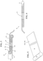
Fig. 5 is top side perspective view of wedge portion. -
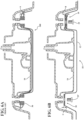
Fig .6A is a top cross-sectional view of a prior art overmolded tether link connected to a vehicle part. -
Fig. 6B is a top cross-sectional view of a multilayered tether link connected to a vehicle part in accordance with one embodiment of the invention. -
Fig. 6C is a top cross-sectional view of a multilayered tether link connected to a vehicle part in accordance with another embodiment of the invention. -
Fig. 7 is a top plan view of a tether according to one embodiment of the invention. -
Fig. 8A is an enlarged perspective view of an alternate tether according to an alternate embodiment of the invention. -
Fig. 8B is an enlarged perspective view of an alternate tether according to an alternate embodiment of the invention. - The following description of the preferred embodiments is merely exemplary in nature and is in no way intended to limit the invention, its application, or uses.
- Referring now to
Fig. 1 there is shown a structuralinner panel 100 of a vehicle liftgate. The structuralinner panel 100 has anoutside surface 112 and an inner surface. The structuralinner panel 100 is covered by an outer panel or outer panels (not shown) that have an exterior show surface. The liftgate structure, and the structuralinner panel 100 are made of composite material, however, it is within the scope of this invention for different materials to be used such as aluminum, manufactured diecast, metal, etc. The structuralinner panel 100 has a lower perimeter surface area 116 extending across substantially the entire width of the structuralinner panel 100. The structuralinner panel 100 also includes a wiper motor housing recess 118 for holding a wiper motor. Also included is a plurality of brackets including aleft side bracket 120, a centerlower bracket 122 and aright side bracket 124. It is within the scope of this invention for a greater or fewer number of brackets to be implemented depending on the particular application. The plurality of brackets are connected to theoutside surface 112 of the structuralinner panel 100. Each of the plurality of brackets also include one or morefriendly holes 126, which are apertures through the respective brackets that allow for atether 12 to pass through. Thefriendly holes 126 each have a curled edge that creates a smooth edge to prevent any snagging of thetether 12 material. - The
tether 12 includes two ends each for connecting thetether 12 to a vehicle part, which in the current embodiment of the invention is awiper motor housing 128 in the wiper motor housing recess 118. Thetether 12 is positioned through each of thefriendly holes 126 of each of theplurality brackets - While the present embodiment of the invention depicts the
tether 12 as being routed through various bracket members, it is within the scope of this invention for thefriendly holes 126, to be formed with the structuralinner panel 100, thereby eliminating the need fordifferent brackets brackets inner panel 100 that are determined to be structurally stronger areas of the liftgate than the portions of the inner panel not located in the tether reinforcement zones. The tether reinforcement zones are best for placement of connections for thetether 12. The structural reinforcement zones allow for thetether 12 to span areas of the composite liftgates that are structurally weaker and will benefit from having thetether 12 passing across the weaker area to be connected to the tether reinforcement zones of the liftgate. The location of the tether reinforcement zones can vary depending upon the design of the liftgate. Factors such as shape, material thickness, material makeup and the dimensions of the liftgate can have an effect on the location of the tether reinforcement zone. Routing thetether 12 between each tether reinforcement zones causes thetether 12 to cross weaker areas of the liftgate to create a type of safety net that will hold the structural inner panel together in the event of breaking of the structural inner panel in the weaker areas between the tether reinforcement zones. - The
tether 12 has a specialized construction forming part of a multilayered tether link that is shown infigures 2-5 ,6B and7 will now be described in greater detail. Thetether 12 has twoends vehicle part 16 using a foldedwedge section 18 and a foldedsection 20 of thetether 12. The foldedwedge section 18 is formed by atether belt material 22 being sinuously folded about at least one wedge portion, which the present embodiment of the invention uses twowedge portions wedge portion tether belt material 22 can be any suitable material, however, in one embodiment of the invention thetether belt material 22 is polyester or mylar material. - As shown the
tether 12 has anend 14a that is folded aboutwedge portion 24a, whileend 14b is folded aboutwedge portion 24b. Thewedge portions Fig. 6C shows amultilayered tether link 200 with atether 202 that has a first foldedsection 204 and a second foldedsection 206 are connected to avehicle part 216. Both the first foldedsection 204 and second foldedsection 206 do not have any wedge portions that are present in themultilayered tether link 10 embodiment shown inFig. 6B . - Referring back to
Figs. 1-5 ,6B and7 , thetether belt material 22 and the twowedge portions hole 28 formed through the layered construction 26 for attachment to avehicle part 16. Thehole 28 is formed ultrasonically using heat knife that prevents fraying. Thehole 28 is configured to allow afastener 29 to pass through the layered construction 26 for connecting thetether 12 to thevehicle part 16. Thewedge portions tether 12 and the stitching in a more consistent manner. Each of the twowedge sections widened end portion 30 and aflat portion 32. Thewidened end portion 30 has a round cross-section and thetether belt material 22 wraps around the radius thewidened end portion 30 when forming the layered construction 26. This helps to eliminate a flat edge in the area where thetether belt material 22 wraps around thewedge section tether belt material 22 and cause failure when force is exerted on themultilayered tether link 10 during a vehicle accident. - The
multilayered tether link 10 further includes a foldedsection 20 having a plurality of layers of sinuously folded tether belt material folded adjacently to form a layeredconstruction 33. In a preferred embodiment thebelt material 22 of the folded section is wound in sinusoidally upon itself to provide an 's' type arrangement. The folded section further includes at least one stitch connecting the plurality of layers together. Also provided is ahole 34 formed through the center of the layeredconstruction 33 for attachment to thevehicle part 16. Thehole 34 is formed ultrasonically using heat knife that prevents fraying. Thevehicle part 16 can be any component of the liftgate and can include the liftgate inner panel, wiper motor housing, support brackets, outer panel of the liftgate, latch mounting bracket or latch actuator housing. - The
vehicle part 16 can be any component of a liftgate for a vehicle and can include the liftgate inner panel, wiper motor housing, support brackets, outer panel of the liftgate, latch mounting bracket or latch actuator housing. Regarding thetether belt material 22, Suitable tether belt materials are selected from the group of woven materials including polyester, nylon, aramid fibers including para-phenylene-terephtalamide, each alone or in combination. - The
multilayered tether link 10 is connected to thevehicle part 16 it will provide controlled release of thetether 12 upon experiencing force of an impact of accident. The controlled release of thetether 12 is provided by the combination of the folding of thetether belt material 22 in the area of the foldedwedge section 18 and the at least one stitch forming the layered construction 26 of the foldedwedge section 18, and the foldedsection 20 and the at least one stitch forming the layeredconstruction 33. Referring now toFig. 7 the stitch details on thetether 12 are shown and described. The foldedwedge section 18 has at least onestitch 36 generally shown. The at least onestitch 36 includes twotight stitch sections transfer stitch sections section 20 has at least onestitch 42 generally shown. The at least onestitch 42 includes twotight stitch sections transfer stitch sections tether 12, forces act on eachtightstitch section transfer stitch section tight stitch section tether 12 and to maximize the absorbance of unwanted forces. - The
multilayered tether link Figs. 1-5 ,6b ,6C and7 provide a significant packaging and force absorption advantage over applications the use an overmolded tether. For example,Fig. 6A shows a prior artovermolded tether 300 connected to the liftgate. As shown the overmolded portions of thetether 300 has overmolded connection features that have a stack height A.Fig. 6B shows that thetether 12 has a stack height B for the foldedwedge section 18 and a stack height C for the foldedsection 20. Both the stack height B and stack height C are much smaller than the stack heigh A attained using thetether 300 with overmolding. Thetether tether 300. - Referring now to
Figs 8A and 8B analternate tether 400 design is shown. Thetether 400 has aloop end 404 with an aperture formed by a loop of the tether material. Aneyelet end 406 of thetether 400 has an aperture for receiving a fastener for connecting thetether 400 to a vehicle part. During connection, theeyelet end 406 is passed through theloop end 404 and secured to the vehicle part. Astopper fold 407 on the eyelet end is created by folding the tether belt material and stitching it together. Theloop end 404 is held in place between thestopper fold 407 and the fastened downeyelet end 406.
Claims (15)
- A multilayered tether link (10) for a vehicle tether (12) comprising:
a tether belt material (22) characterized by having a folded wedge section (18) formed by the tether belt material (22) being sinuously folded about at least one wedge portion (24a, 24b), wherein the tether belt material (22) and the at least one wedge portion (24a, 24b) are sewn together with at least one stitch (36) to form a layered construction (26) and a hole (28) is formed through the layered construction (26) for attachment to a vehicle part (16). - The multilayered tether link (10) of claim 1, comprising a folded section (20) having a plurality of layers of sinuously folded tether belt material (22) folded adjacently to form a layered construction (33), where the layered construction (33) of the folded section (20) includes at least one stitch (42) connecting the plurality of layers together and a hole (34) formed through the center of the folded section (20) for attachment to a vehicle part (16).
- The multilayered tether link (10) of claim 1 or 2, wherein the at least one wedge portion (24a, 24b) has a flat portion (32) and a widened end portion (30), where the tether belt material (22) wraps around the widened end portion (30) and the hole (28) is formed through the flat portion (32).
- The multilayered tether link (10) of claim 1 or 2, further comprising:wherein the at least one wedge portion (24a, 24b) of the folded wedge section (18) includes a first wedge portion (24a) and a second wedge portion (24b), wherein a first end (14a) of the tether belt material (22) is wound around the first wedge portion (24a) and a second end (14b) of the tether belt material (22) is wound around the second wedge portion (24b), and the first wedge portion (24a) with the tether belt material (22) of the first end (14a) are placed adjacent the second wedge portion (24b) with the tether belt material (22) of the second end (14b) wound around the second wedge portion (24b) to create the layered construction (26), andthe hole (28) is formed through the layered construction (26).
- The multilayered tether link (10) of claim 4, wherein the first wedge portion (24a) and the second wedge portion (24b) each have a flat portion (32) and a widened end portion (30), where the first end (14a) of the tether belt material (22) wraps around the widened end portion (30) of the first wedge portion (24a) and the hole (28) is formed through the flat portion (32), the second end (14b) of the tether belt material (22) wraps around the widened end portion (30) of the second wedge portion (24b) and the hole (28) is formed through the flat portion (32).
- The multilayered tether link (10) of claim 1, wherein the at least one stitch (36) of the layered construction (26) is releasable if a predetermined amount of force is experienced by the tether belt material (22).
- The multilayered tether link (10) of claim 1 or 2, wherein the hole (28) in the folded wedge section (18) is formed ultrasonically, or wherein the hole (28) in the folded wedge section (18) and the hole (34) in the folded section (20) are formed ultrasonically.
- The multilayered tether link (10) of claim 1 or 2, wherein the tether belt material (22) is one of a polyester or mylar material that is cut with a heat knife to prevent fraying.
- The multilayered tether link (10) of claim 2, wherein the folded section (20) includes a portion of the tether belt material (22) being folded twice back on the tether belt material (22) and sewn together for forming a three layered construction (33).
- The multilayered tether link (10) of claim 9, wherein the hole (34) in the folded section (20) is ultrasonically cut through the three layered construction (33)
- The multilayer tether link of claim 1 or 2, wherein the at least one stitch (36) of the folded wedge section (18) includes at least two tight stitch sections (38a, 38b) joined by at least one load transfer stitch section (40a, 40b) to provide a controlled break at a predetermined force.
- A multilayered tether link (200) for a vehicle tether (202) comprising:a first folded section (204) having a plurality of layers of sinuously folded tether belt material (22) folded adjacently to form a layered construction (33), where the layered construction (33) of the folded section includes at least one stitch (42) connecting the plurality of layers together and characterized by a hole (34) formed through the center of the first folded section (204) for attachment to a vehicle part (216), and bya second folded section (206) having a plurality of layers of sinuously folded tether belt material (22) folded adjacently to form a layered construction (33), where the layered construction (33) of the folded section includes at least one stitch (42) connecting the plurality of layers together and a hole (34) formed through the center of the second folded section (206) for attachment to a vehicle part (216).
- The multilayered tether link (200) of claim 12, wherein the hole (34) in the first folded section (204) and the hole (34) in the second folded section (206) are formed ultrasonically, or wherein the tether belt material (22) is one of a polyester or mylar material that is cut with a heat knife to prevent fraying.
- The multilayered tether link (200) of claim 12, wherein the second folded section (206) both include a portion of the tether belt material (22) being folded twice back on the tether belt material (22) and sewn together for forming a three layered construction (33).
- The multilayer tether link of claim 12, wherein the at least one stitch (42) of the first folded section (204) and the at least one stitch (42) of the second folded section (206) each include at least two tight stitch sections (44a, 44b) joined by at least one load transfer stitch section (46a, 46b) to provide a controlled break at a predetermined force.
Applications Claiming Priority (2)
| Application Number | Priority Date | Filing Date | Title |
|---|---|---|---|
| US202163139326P | 2021-01-20 | 2021-01-20 | |
| PCT/US2022/013071 WO2022159551A1 (en) | 2021-01-20 | 2022-01-20 | Multilayered tether link for liftgate |
Publications (3)
| Publication Number | Publication Date |
|---|---|
| EP4263253A1 EP4263253A1 (en) | 2023-10-25 |
| EP4263253B1 true EP4263253B1 (en) | 2024-08-21 |
| EP4263253B8 EP4263253B8 (en) | 2024-10-02 |
Family
ID=80447920
Family Applications (1)
| Application Number | Title | Priority Date | Filing Date |
|---|---|---|---|
| EP22704070.6A Active EP4263253B8 (en) | 2021-01-20 | 2022-01-20 | Multilayered tether link for liftgate |
Country Status (6)
| Country | Link |
|---|---|
| US (1) | US20240300307A1 (en) |
| EP (1) | EP4263253B8 (en) |
| KR (1) | KR102898815B1 (en) |
| CN (1) | CN116829389A (en) |
| CA (1) | CA3204527A1 (en) |
| WO (1) | WO2022159551A1 (en) |
Families Citing this family (1)
| Publication number | Priority date | Publication date | Assignee | Title |
|---|---|---|---|---|
| USD1089023S1 (en) * | 2023-08-17 | 2025-08-19 | Hyundai Motor Company | Tailgate panel for an automobile |
Family Cites Families (22)
| Publication number | Priority date | Publication date | Assignee | Title |
|---|---|---|---|---|
| JPH01144153U (en) * | 1988-03-11 | 1989-10-03 | ||
| JP3168591B2 (en) * | 1991-03-12 | 2001-05-21 | トヨタ自動車株式会社 | Airbag device |
| DE4328746C2 (en) * | 1993-08-26 | 1995-08-24 | Baumeister & Ostler Gmbh Co | Safety net arrangement |
| DE4423741A1 (en) * | 1994-07-06 | 1996-01-18 | Bayerische Motoren Werke Ag | Side impact protection belt for vehicles of synthetic yarns |
| JP3114051B2 (en) * | 1995-12-05 | 2000-12-04 | 本田技研工業株式会社 | Mounting structure for seat belt retractor |
| US20020104190A1 (en) * | 2001-01-23 | 2002-08-08 | Donal Moore | Child tether cover |
| US6616184B2 (en) * | 2001-04-25 | 2003-09-09 | Trw Vehicle Safety Systems Inc. | Vehicle occupant protection apparatus with inflation volume and shape control |
| JP2006068984A (en) * | 2004-09-01 | 2006-03-16 | Japan Network Service:Kk | Cutting device for transcript |
| US8016526B2 (en) * | 2006-12-22 | 2011-09-13 | Brian Flannigan | Tie down anchor device |
| US8650721B2 (en) * | 2007-09-11 | 2014-02-18 | Autoliv Development Ab | Buckle device for seat belt and manufacturing method thereof |
| JP2011081917A (en) * | 2009-10-02 | 2011-04-21 | Suminoe Textile Co Ltd | Cloth with linear heater, and manufacturing method thereof |
| US8360469B2 (en) * | 2010-08-27 | 2013-01-29 | Tk Holdings Inc. | Airbag system |
| PL2766230T3 (en) * | 2011-10-12 | 2016-06-30 | Key Safety Systems Inc | Air bag assembly and tether |
| EP2666665B1 (en) * | 2012-05-25 | 2018-07-11 | Volvo Car Corporation | A tether anchorage |
| KR20140035141A (en) * | 2012-09-13 | 2014-03-21 | 현대모비스 주식회사 | Airbag apparatus |
| JP6322179B2 (en) * | 2015-12-16 | 2018-05-09 | 本田技研工業株式会社 | Tailgate structure |
| US11634013B2 (en) * | 2017-06-30 | 2023-04-25 | Magna Exteriors, Inc. | Liftgate reinforcement arrangements |
| CN207697460U (en) * | 2018-01-10 | 2018-08-07 | 延锋彼欧汽车外饰系统有限公司 | A kind of composite material tail-gate |
| CN108263182A (en) * | 2018-01-10 | 2018-07-10 | 延锋彼欧汽车外饰系统有限公司 | A kind of composite material tail-gate |
| FR3090535B1 (en) * | 2018-12-21 | 2020-12-04 | Plastic Omnium Cie | Body part including a locking buckle |
| CN217197723U (en) * | 2021-12-30 | 2022-08-16 | 上海纪田实业有限公司 | Automobile tail gate pull belt |
| CN114103610A (en) * | 2021-12-30 | 2022-03-01 | 上海纪田实业有限公司 | Automobile tail gate pull belt and installation method |
-
2022
- 2022-01-20 EP EP22704070.6A patent/EP4263253B8/en active Active
- 2022-01-20 CN CN202280010593.2A patent/CN116829389A/en active Pending
- 2022-01-20 KR KR1020237024640A patent/KR102898815B1/en active Active
- 2022-01-20 WO PCT/US2022/013071 patent/WO2022159551A1/en not_active Ceased
- 2022-01-20 CA CA3204527A patent/CA3204527A1/en active Pending
- 2022-01-20 US US18/260,486 patent/US20240300307A1/en active Pending
Also Published As
| Publication number | Publication date |
|---|---|
| WO2022159551A1 (en) | 2022-07-28 |
| EP4263253B8 (en) | 2024-10-02 |
| US20240300307A1 (en) | 2024-09-12 |
| CA3204527A1 (en) | 2022-07-28 |
| CN116829389A (en) | 2023-09-29 |
| KR102898815B1 (en) | 2025-12-11 |
| EP4263253A1 (en) | 2023-10-25 |
| KR20230122112A (en) | 2023-08-22 |
Similar Documents
| Publication | Publication Date | Title |
|---|---|---|
| AU762588B2 (en) | Reinforcement of instrument panel | |
| EP3981624B1 (en) | Liftgate reinforcement arrangements | |
| CN110949529A (en) | Side body structure of vehicle | |
| US8985674B2 (en) | Door trim for vehicle | |
| US20240300307A1 (en) | Multilayered tether link for liftgate | |
| KR102736188B1 (en) | Bodywork including a locking loop | |
| US6056349A (en) | Vehicle door having improved side crash resistance and associated method | |
| JP5734174B2 (en) | Auto body structure | |
| US11541941B2 (en) | Front vehicle-body structure for vehicle | |
| JP2008001196A (en) | Passenger airbag | |
| EP4520600B1 (en) | Vehicle interior panel for use over an airbag | |
| JP2002284038A (en) | Automotive panels | |
| JP7416657B2 (en) | composite structure | |
| EP2377730A1 (en) | Airbag Module | |
| KR102598951B1 (en) | Pillar reinforcement structure | |
| CN115123041B (en) | Composite member, automobile seat, and automobile component | |
| JPS607970Y2 (en) | car body structure | |
| JP7764982B2 (en) | Bracket holding structure | |
| CN115871794B (en) | Vehicle body components and vehicles | |
| JP4022829B2 (en) | Seat belt anchor mounting structure | |
| JP2000255447A (en) | Car front frame structure | |
| JP7430972B2 (en) | vehicle structure | |
| KR102738764B1 (en) | Steel High Roof Assembly Of Vehicle | |
| JP2020044929A (en) | Vehicular center pillar | |
| US10112567B2 (en) | Knee bolster of glove box for vehicle |
Legal Events
| Date | Code | Title | Description |
|---|---|---|---|
| STAA | Information on the status of an ep patent application or granted ep patent |
Free format text: STATUS: UNKNOWN |
|
| STAA | Information on the status of an ep patent application or granted ep patent |
Free format text: STATUS: THE INTERNATIONAL PUBLICATION HAS BEEN MADE |
|
| PUAI | Public reference made under article 153(3) epc to a published international application that has entered the european phase |
Free format text: ORIGINAL CODE: 0009012 |
|
| STAA | Information on the status of an ep patent application or granted ep patent |
Free format text: STATUS: REQUEST FOR EXAMINATION WAS MADE |
|
| 17P | Request for examination filed |
Effective date: 20230717 |
|
| AK | Designated contracting states |
Kind code of ref document: A1 Designated state(s): AL AT BE BG CH CY CZ DE DK EE ES FI FR GB GR HR HU IE IS IT LI LT LU LV MC MK MT NL NO PL PT RO RS SE SI SK SM TR |
|
| GRAP | Despatch of communication of intention to grant a patent |
Free format text: ORIGINAL CODE: EPIDOSNIGR1 |
|
| STAA | Information on the status of an ep patent application or granted ep patent |
Free format text: STATUS: GRANT OF PATENT IS INTENDED |
|
| INTG | Intention to grant announced |
Effective date: 20240312 |
|
| DAV | Request for validation of the european patent (deleted) | ||
| DAX | Request for extension of the european patent (deleted) | ||
| GRAS | Grant fee paid |
Free format text: ORIGINAL CODE: EPIDOSNIGR3 |
|
| GRAA | (expected) grant |
Free format text: ORIGINAL CODE: 0009210 |
|
| STAA | Information on the status of an ep patent application or granted ep patent |
Free format text: STATUS: THE PATENT HAS BEEN GRANTED |
|
| AK | Designated contracting states |
Kind code of ref document: B1 Designated state(s): AL AT BE BG CH CY CZ DE DK EE ES FI FR GB GR HR HU IE IS IT LI LT LU LV MC MK MT NL NO PL PT RO RS SE SI SK SM TR |
|
| REG | Reference to a national code |
Ref country code: GB Ref legal event code: FG4D |
|
| REG | Reference to a national code |
Ref country code: DE Ref legal event code: R081 Ref document number: 602022005510 Country of ref document: DE Owner name: MAGNA EXTERIORS INC., AURORA, CA Free format text: FORMER OWNER: MAGNA EXTERIORS INC., CONCORD, ONTARIO, CA |
|
| REG | Reference to a national code |
Ref country code: CH Ref legal event code: EP |
|
| RAP4 | Party data changed (patent owner data changed or rights of a patent transferred) |
Owner name: MAGNA EXTERIORS INC. |
|
| REG | Reference to a national code |
Ref country code: IE Ref legal event code: FG4D |
|
| REG | Reference to a national code |
Ref country code: DE Ref legal event code: R096 Ref document number: 602022005510 Country of ref document: DE |
|
| REG | Reference to a national code |
Ref country code: CH Ref legal event code: PK Free format text: BERICHTIGUNG B8 |
|
| P01 | Opt-out of the competence of the unified patent court (upc) registered |
Free format text: CASE NUMBER: APP_56785/2024 Effective date: 20241017 |
|
| REG | Reference to a national code |
Ref country code: LT Ref legal event code: MG9D |
|
| REG | Reference to a national code |
Ref country code: NL Ref legal event code: MP Effective date: 20240821 |
|
| PG25 | Lapsed in a contracting state [announced via postgrant information from national office to epo] |
Ref country code: NO Free format text: LAPSE BECAUSE OF FAILURE TO SUBMIT A TRANSLATION OF THE DESCRIPTION OR TO PAY THE FEE WITHIN THE PRESCRIBED TIME-LIMIT Effective date: 20241121 |
|
| REG | Reference to a national code |
Ref country code: AT Ref legal event code: MK05 Ref document number: 1715205 Country of ref document: AT Kind code of ref document: T Effective date: 20240821 |
|
| PG25 | Lapsed in a contracting state [announced via postgrant information from national office to epo] |
Ref country code: NL Free format text: LAPSE BECAUSE OF FAILURE TO SUBMIT A TRANSLATION OF THE DESCRIPTION OR TO PAY THE FEE WITHIN THE PRESCRIBED TIME-LIMIT Effective date: 20240821 Ref country code: PL Free format text: LAPSE BECAUSE OF FAILURE TO SUBMIT A TRANSLATION OF THE DESCRIPTION OR TO PAY THE FEE WITHIN THE PRESCRIBED TIME-LIMIT Effective date: 20240821 Ref country code: FI Free format text: LAPSE BECAUSE OF FAILURE TO SUBMIT A TRANSLATION OF THE DESCRIPTION OR TO PAY THE FEE WITHIN THE PRESCRIBED TIME-LIMIT Effective date: 20240821 Ref country code: GR Free format text: LAPSE BECAUSE OF FAILURE TO SUBMIT A TRANSLATION OF THE DESCRIPTION OR TO PAY THE FEE WITHIN THE PRESCRIBED TIME-LIMIT Effective date: 20241122 Ref country code: PT Free format text: LAPSE BECAUSE OF FAILURE TO SUBMIT A TRANSLATION OF THE DESCRIPTION OR TO PAY THE FEE WITHIN THE PRESCRIBED TIME-LIMIT Effective date: 20241223 |
|
| PG25 | Lapsed in a contracting state [announced via postgrant information from national office to epo] |
Ref country code: BG Free format text: LAPSE BECAUSE OF FAILURE TO SUBMIT A TRANSLATION OF THE DESCRIPTION OR TO PAY THE FEE WITHIN THE PRESCRIBED TIME-LIMIT Effective date: 20240821 |
|
| PG25 | Lapsed in a contracting state [announced via postgrant information from national office to epo] |
Ref country code: LV Free format text: LAPSE BECAUSE OF FAILURE TO SUBMIT A TRANSLATION OF THE DESCRIPTION OR TO PAY THE FEE WITHIN THE PRESCRIBED TIME-LIMIT Effective date: 20240821 |
|
| PG25 | Lapsed in a contracting state [announced via postgrant information from national office to epo] |
Ref country code: AT Free format text: LAPSE BECAUSE OF FAILURE TO SUBMIT A TRANSLATION OF THE DESCRIPTION OR TO PAY THE FEE WITHIN THE PRESCRIBED TIME-LIMIT Effective date: 20240821 Ref country code: IS Free format text: LAPSE BECAUSE OF FAILURE TO SUBMIT A TRANSLATION OF THE DESCRIPTION OR TO PAY THE FEE WITHIN THE PRESCRIBED TIME-LIMIT Effective date: 20241221 |
|
| PG25 | Lapsed in a contracting state [announced via postgrant information from national office to epo] |
Ref country code: HR Free format text: LAPSE BECAUSE OF FAILURE TO SUBMIT A TRANSLATION OF THE DESCRIPTION OR TO PAY THE FEE WITHIN THE PRESCRIBED TIME-LIMIT Effective date: 20240821 |
|
| PG25 | Lapsed in a contracting state [announced via postgrant information from national office to epo] |
Ref country code: RS Free format text: LAPSE BECAUSE OF FAILURE TO SUBMIT A TRANSLATION OF THE DESCRIPTION OR TO PAY THE FEE WITHIN THE PRESCRIBED TIME-LIMIT Effective date: 20241121 Ref country code: ES Free format text: LAPSE BECAUSE OF FAILURE TO SUBMIT A TRANSLATION OF THE DESCRIPTION OR TO PAY THE FEE WITHIN THE PRESCRIBED TIME-LIMIT Effective date: 20240821 |
|
| PG25 | Lapsed in a contracting state [announced via postgrant information from national office to epo] |
Ref country code: RS Free format text: LAPSE BECAUSE OF FAILURE TO SUBMIT A TRANSLATION OF THE DESCRIPTION OR TO PAY THE FEE WITHIN THE PRESCRIBED TIME-LIMIT Effective date: 20241121 Ref country code: PT Free format text: LAPSE BECAUSE OF FAILURE TO SUBMIT A TRANSLATION OF THE DESCRIPTION OR TO PAY THE FEE WITHIN THE PRESCRIBED TIME-LIMIT Effective date: 20241223 Ref country code: PL Free format text: LAPSE BECAUSE OF FAILURE TO SUBMIT A TRANSLATION OF THE DESCRIPTION OR TO PAY THE FEE WITHIN THE PRESCRIBED TIME-LIMIT Effective date: 20240821 Ref country code: NO Free format text: LAPSE BECAUSE OF FAILURE TO SUBMIT A TRANSLATION OF THE DESCRIPTION OR TO PAY THE FEE WITHIN THE PRESCRIBED TIME-LIMIT Effective date: 20241121 Ref country code: NL Free format text: LAPSE BECAUSE OF FAILURE TO SUBMIT A TRANSLATION OF THE DESCRIPTION OR TO PAY THE FEE WITHIN THE PRESCRIBED TIME-LIMIT Effective date: 20240821 Ref country code: LV Free format text: LAPSE BECAUSE OF FAILURE TO SUBMIT A TRANSLATION OF THE DESCRIPTION OR TO PAY THE FEE WITHIN THE PRESCRIBED TIME-LIMIT Effective date: 20240821 Ref country code: IS Free format text: LAPSE BECAUSE OF FAILURE TO SUBMIT A TRANSLATION OF THE DESCRIPTION OR TO PAY THE FEE WITHIN THE PRESCRIBED TIME-LIMIT Effective date: 20241221 Ref country code: HR Free format text: LAPSE BECAUSE OF FAILURE TO SUBMIT A TRANSLATION OF THE DESCRIPTION OR TO PAY THE FEE WITHIN THE PRESCRIBED TIME-LIMIT Effective date: 20240821 Ref country code: GR Free format text: LAPSE BECAUSE OF FAILURE TO SUBMIT A TRANSLATION OF THE DESCRIPTION OR TO PAY THE FEE WITHIN THE PRESCRIBED TIME-LIMIT Effective date: 20241122 Ref country code: FI Free format text: LAPSE BECAUSE OF FAILURE TO SUBMIT A TRANSLATION OF THE DESCRIPTION OR TO PAY THE FEE WITHIN THE PRESCRIBED TIME-LIMIT Effective date: 20240821 Ref country code: ES Free format text: LAPSE BECAUSE OF FAILURE TO SUBMIT A TRANSLATION OF THE DESCRIPTION OR TO PAY THE FEE WITHIN THE PRESCRIBED TIME-LIMIT Effective date: 20240821 Ref country code: BG Free format text: LAPSE BECAUSE OF FAILURE TO SUBMIT A TRANSLATION OF THE DESCRIPTION OR TO PAY THE FEE WITHIN THE PRESCRIBED TIME-LIMIT Effective date: 20240821 Ref country code: AT Free format text: LAPSE BECAUSE OF FAILURE TO SUBMIT A TRANSLATION OF THE DESCRIPTION OR TO PAY THE FEE WITHIN THE PRESCRIBED TIME-LIMIT Effective date: 20240821 |
|
| REG | Reference to a national code |
Ref country code: DE Ref legal event code: R082 Ref document number: 602022005510 Country of ref document: DE Representative=s name: WITTE, WELLER & PARTNER PATENTANWAELTE MBB, DE |
|
| PG25 | Lapsed in a contracting state [announced via postgrant information from national office to epo] |
Ref country code: DK Free format text: LAPSE BECAUSE OF FAILURE TO SUBMIT A TRANSLATION OF THE DESCRIPTION OR TO PAY THE FEE WITHIN THE PRESCRIBED TIME-LIMIT Effective date: 20240821 Ref country code: SM Free format text: LAPSE BECAUSE OF FAILURE TO SUBMIT A TRANSLATION OF THE DESCRIPTION OR TO PAY THE FEE WITHIN THE PRESCRIBED TIME-LIMIT Effective date: 20240821 Ref country code: RO Free format text: LAPSE BECAUSE OF FAILURE TO SUBMIT A TRANSLATION OF THE DESCRIPTION OR TO PAY THE FEE WITHIN THE PRESCRIBED TIME-LIMIT Effective date: 20240821 |
|
| PG25 | Lapsed in a contracting state [announced via postgrant information from national office to epo] |
Ref country code: CZ Free format text: LAPSE BECAUSE OF FAILURE TO SUBMIT A TRANSLATION OF THE DESCRIPTION OR TO PAY THE FEE WITHIN THE PRESCRIBED TIME-LIMIT Effective date: 20240821 |
|
| PG25 | Lapsed in a contracting state [announced via postgrant information from national office to epo] |
Ref country code: IT Free format text: LAPSE BECAUSE OF FAILURE TO SUBMIT A TRANSLATION OF THE DESCRIPTION OR TO PAY THE FEE WITHIN THE PRESCRIBED TIME-LIMIT Effective date: 20240821 Ref country code: SK Free format text: LAPSE BECAUSE OF FAILURE TO SUBMIT A TRANSLATION OF THE DESCRIPTION OR TO PAY THE FEE WITHIN THE PRESCRIBED TIME-LIMIT Effective date: 20240821 |
|
| REG | Reference to a national code |
Ref country code: DE Ref legal event code: R097 Ref document number: 602022005510 Country of ref document: DE |
|
| PLBE | No opposition filed within time limit |
Free format text: ORIGINAL CODE: 0009261 |
|
| STAA | Information on the status of an ep patent application or granted ep patent |
Free format text: STATUS: NO OPPOSITION FILED WITHIN TIME LIMIT |
|
| 26N | No opposition filed |
Effective date: 20250522 |
|
| REG | Reference to a national code |
Ref country code: CH Ref legal event code: PL |
|
| PG25 | Lapsed in a contracting state [announced via postgrant information from national office to epo] |
Ref country code: SE Free format text: LAPSE BECAUSE OF FAILURE TO SUBMIT A TRANSLATION OF THE DESCRIPTION OR TO PAY THE FEE WITHIN THE PRESCRIBED TIME-LIMIT Effective date: 20240821 |
|
| PG25 | Lapsed in a contracting state [announced via postgrant information from national office to epo] |
Ref country code: MC Free format text: LAPSE BECAUSE OF FAILURE TO SUBMIT A TRANSLATION OF THE DESCRIPTION OR TO PAY THE FEE WITHIN THE PRESCRIBED TIME-LIMIT Effective date: 20240821 Ref country code: LU Free format text: LAPSE BECAUSE OF NON-PAYMENT OF DUE FEES Effective date: 20250120 |
|
| PG25 | Lapsed in a contracting state [announced via postgrant information from national office to epo] |
Ref country code: BE Free format text: LAPSE BECAUSE OF NON-PAYMENT OF DUE FEES Effective date: 20250131 |
|
| PG25 | Lapsed in a contracting state [announced via postgrant information from national office to epo] |
Ref country code: CH Free format text: LAPSE BECAUSE OF NON-PAYMENT OF DUE FEES Effective date: 20250131 |
|
| REG | Reference to a national code |
Ref country code: BE Ref legal event code: MM Effective date: 20250131 |
|
| PGFP | Annual fee paid to national office [announced via postgrant information from national office to epo] |
Ref country code: GB Payment date: 20251204 Year of fee payment: 5 |
|
| PGFP | Annual fee paid to national office [announced via postgrant information from national office to epo] |
Ref country code: FR Payment date: 20251128 Year of fee payment: 5 |
|
| PG25 | Lapsed in a contracting state [announced via postgrant information from national office to epo] |
Ref country code: IE Free format text: LAPSE BECAUSE OF NON-PAYMENT OF DUE FEES Effective date: 20250120 |
|
| PGFP | Annual fee paid to national office [announced via postgrant information from national office to epo] |
Ref country code: DE Payment date: 20251203 Year of fee payment: 5 |