EP4262074A1 - Soft start for buck converters - Google Patents
Soft start for buck converters Download PDFInfo
- Publication number
- EP4262074A1 EP4262074A1 EP23167425.0A EP23167425A EP4262074A1 EP 4262074 A1 EP4262074 A1 EP 4262074A1 EP 23167425 A EP23167425 A EP 23167425A EP 4262074 A1 EP4262074 A1 EP 4262074A1
- Authority
- EP
- European Patent Office
- Prior art keywords
- voltage
- buck converter
- soft start
- current
- link voltage
- Prior art date
- Legal status (The legal status is an assumption and is not a legal conclusion. Google has not performed a legal analysis and makes no representation as to the accuracy of the status listed.)
- Pending
Links
- 238000000034 method Methods 0.000 claims abstract description 32
- 230000004044 response Effects 0.000 claims abstract description 14
- 238000006243 chemical reaction Methods 0.000 claims abstract description 8
- 239000003990 capacitor Substances 0.000 claims description 6
- 238000004804 winding Methods 0.000 claims description 2
- 230000006870 function Effects 0.000 description 17
- 238000004590 computer program Methods 0.000 description 8
- 238000010586 diagram Methods 0.000 description 6
- 230000001360 synchronised effect Effects 0.000 description 4
- 230000003287 optical effect Effects 0.000 description 3
- 239000013307 optical fiber Substances 0.000 description 2
- 230000008569 process Effects 0.000 description 2
- 230000000644 propagated effect Effects 0.000 description 2
- 230000008859 change Effects 0.000 description 1
- 238000007796 conventional method Methods 0.000 description 1
- 230000001419 dependent effect Effects 0.000 description 1
- 230000010354 integration Effects 0.000 description 1
- 238000004519 manufacturing process Methods 0.000 description 1
- 238000012986 modification Methods 0.000 description 1
- 230000004048 modification Effects 0.000 description 1
- 239000004065 semiconductor Substances 0.000 description 1
- 239000007787 solid Substances 0.000 description 1
Images


Classifications
-
- H—ELECTRICITY
- H02—GENERATION; CONVERSION OR DISTRIBUTION OF ELECTRIC POWER
- H02M—APPARATUS FOR CONVERSION BETWEEN AC AND AC, BETWEEN AC AND DC, OR BETWEEN DC AND DC, AND FOR USE WITH MAINS OR SIMILAR POWER SUPPLY SYSTEMS; CONVERSION OF DC OR AC INPUT POWER INTO SURGE OUTPUT POWER; CONTROL OR REGULATION THEREOF
- H02M3/00—Conversion of DC power input into DC power output
- H02M3/02—Conversion of DC power input into DC power output without intermediate conversion into AC
- H02M3/04—Conversion of DC power input into DC power output without intermediate conversion into AC by static converters
- H02M3/10—Conversion of DC power input into DC power output without intermediate conversion into AC by static converters using discharge tubes with control electrode or semiconductor devices with control electrode
- H02M3/145—Conversion of DC power input into DC power output without intermediate conversion into AC by static converters using discharge tubes with control electrode or semiconductor devices with control electrode using devices of a triode or transistor type requiring continuous application of a control signal
- H02M3/155—Conversion of DC power input into DC power output without intermediate conversion into AC by static converters using discharge tubes with control electrode or semiconductor devices with control electrode using devices of a triode or transistor type requiring continuous application of a control signal using semiconductor devices only
- H02M3/156—Conversion of DC power input into DC power output without intermediate conversion into AC by static converters using discharge tubes with control electrode or semiconductor devices with control electrode using devices of a triode or transistor type requiring continuous application of a control signal using semiconductor devices only with automatic control of output voltage or current, e.g. switching regulators
- H02M3/158—Conversion of DC power input into DC power output without intermediate conversion into AC by static converters using discharge tubes with control electrode or semiconductor devices with control electrode using devices of a triode or transistor type requiring continuous application of a control signal using semiconductor devices only with automatic control of output voltage or current, e.g. switching regulators including plural semiconductor devices as final control devices for a single load
-
- H—ELECTRICITY
- H02—GENERATION; CONVERSION OR DISTRIBUTION OF ELECTRIC POWER
- H02M—APPARATUS FOR CONVERSION BETWEEN AC AND AC, BETWEEN AC AND DC, OR BETWEEN DC AND DC, AND FOR USE WITH MAINS OR SIMILAR POWER SUPPLY SYSTEMS; CONVERSION OF DC OR AC INPUT POWER INTO SURGE OUTPUT POWER; CONTROL OR REGULATION THEREOF
- H02M1/00—Details of apparatus for conversion
- H02M1/36—Means for starting or stopping converters
-
- H—ELECTRICITY
- H02—GENERATION; CONVERSION OR DISTRIBUTION OF ELECTRIC POWER
- H02M—APPARATUS FOR CONVERSION BETWEEN AC AND AC, BETWEEN AC AND DC, OR BETWEEN DC AND DC, AND FOR USE WITH MAINS OR SIMILAR POWER SUPPLY SYSTEMS; CONVERSION OF DC OR AC INPUT POWER INTO SURGE OUTPUT POWER; CONTROL OR REGULATION THEREOF
- H02M1/00—Details of apparatus for conversion
- H02M1/0003—Details of control, feedback or regulation circuits
- H02M1/0025—Arrangements for modifying reference values, feedback values or error values in the control loop of a converter
-
- H—ELECTRICITY
- H02—GENERATION; CONVERSION OR DISTRIBUTION OF ELECTRIC POWER
- H02M—APPARATUS FOR CONVERSION BETWEEN AC AND AC, BETWEEN AC AND DC, OR BETWEEN DC AND DC, AND FOR USE WITH MAINS OR SIMILAR POWER SUPPLY SYSTEMS; CONVERSION OF DC OR AC INPUT POWER INTO SURGE OUTPUT POWER; CONTROL OR REGULATION THEREOF
- H02M3/00—Conversion of DC power input into DC power output
- H02M3/02—Conversion of DC power input into DC power output without intermediate conversion into AC
- H02M3/04—Conversion of DC power input into DC power output without intermediate conversion into AC by static converters
- H02M3/10—Conversion of DC power input into DC power output without intermediate conversion into AC by static converters using discharge tubes with control electrode or semiconductor devices with control electrode
- H02M3/145—Conversion of DC power input into DC power output without intermediate conversion into AC by static converters using discharge tubes with control electrode or semiconductor devices with control electrode using devices of a triode or transistor type requiring continuous application of a control signal
- H02M3/155—Conversion of DC power input into DC power output without intermediate conversion into AC by static converters using discharge tubes with control electrode or semiconductor devices with control electrode using devices of a triode or transistor type requiring continuous application of a control signal using semiconductor devices only
- H02M3/156—Conversion of DC power input into DC power output without intermediate conversion into AC by static converters using discharge tubes with control electrode or semiconductor devices with control electrode using devices of a triode or transistor type requiring continuous application of a control signal using semiconductor devices only with automatic control of output voltage or current, e.g. switching regulators
- H02M3/157—Conversion of DC power input into DC power output without intermediate conversion into AC by static converters using discharge tubes with control electrode or semiconductor devices with control electrode using devices of a triode or transistor type requiring continuous application of a control signal using semiconductor devices only with automatic control of output voltage or current, e.g. switching regulators with digital control
-
- H—ELECTRICITY
- H02—GENERATION; CONVERSION OR DISTRIBUTION OF ELECTRIC POWER
- H02M—APPARATUS FOR CONVERSION BETWEEN AC AND AC, BETWEEN AC AND DC, OR BETWEEN DC AND DC, AND FOR USE WITH MAINS OR SIMILAR POWER SUPPLY SYSTEMS; CONVERSION OF DC OR AC INPUT POWER INTO SURGE OUTPUT POWER; CONTROL OR REGULATION THEREOF
- H02M1/00—Details of apparatus for conversion
- H02M1/0003—Details of control, feedback or regulation circuits
- H02M1/0016—Control circuits providing compensation of output voltage deviations using feedforward of disturbance parameters
- H02M1/0019—Control circuits providing compensation of output voltage deviations using feedforward of disturbance parameters the disturbance parameters being load current fluctuations
-
- H—ELECTRICITY
- H02—GENERATION; CONVERSION OR DISTRIBUTION OF ELECTRIC POWER
- H02M—APPARATUS FOR CONVERSION BETWEEN AC AND AC, BETWEEN AC AND DC, OR BETWEEN DC AND DC, AND FOR USE WITH MAINS OR SIMILAR POWER SUPPLY SYSTEMS; CONVERSION OF DC OR AC INPUT POWER INTO SURGE OUTPUT POWER; CONTROL OR REGULATION THEREOF
- H02M1/00—Details of apparatus for conversion
- H02M1/0003—Details of control, feedback or regulation circuits
- H02M1/0016—Control circuits providing compensation of output voltage deviations using feedforward of disturbance parameters
- H02M1/0022—Control circuits providing compensation of output voltage deviations using feedforward of disturbance parameters the disturbance parameters being input voltage fluctuations
Definitions
- the present disclosure relates to power conversion, and more particularly to buck converters for stepping an input voltage down to a lower output voltage.
- Buck converters can step down an input or link voltage to a lower output voltage.
- Buck synchronous and standard power converters with a wide input range e.g. 90VDC to 600VDC, which is a much wider input range than in traditional applications, can cause problems on loads on the output voltage because at start up there is not a smooth, robust output voltage.
- a method of DC-DC power conversion includes converting a DC link voltage to a DC output voltage for a load that is lower than the DC link voltage using a buck converter.
- the method includes controlling the buck converter in a normal switching mode in response to the DC link voltage being below a predetermined high threshold.
- the method also includes controlling the buck converter in a soft start switching mode in response to the DC link voltage being at or above the predetermined high threshold.
- Controlling the buck converter in the soft start switching mode can include latching the soft start switching mode in an enabled state upon occurrence of enablement of voltage regulation in the buck converter, the DC link voltage being at or above the predetermined high threshold, to keep the rate limited switching mode enabled even if the DC link voltage drops below the predetermined high threshold after latching, and the DC output voltage being at or below a predetermined initial soft start voltage limit.
- Controlling the buck boost converter in the soft start switching mode can include latching the soft start switching mode in an enabled state upon occurrence of the DC output voltage being at or above a predetermined final soft start voltage, and load current being at or above a predetermined soft start current limit.
- the method can include resetting the enabled state of the soft start switching mode upon disabling of voltage regulation in the buck converter.
- Controlling the buck converter in the normal switching mode can include controlling current to the load based on measured current supplied to the buck converter at the DC Link Voltage, and a commanded inductor current for controlling current in a main inductor of the buck converter.
- the commanded inductor current for controlling the current in the main inductor can be derived from a voltage regulation control signal that is based on a differential of commanded output voltage and measured output voltage to the load.
- Controlling the buck converter in the soft start switching mode can include controlling current to the load based on measured current supplied to the load, measured current supplied to the buck converter at the DC Link Voltage, and a commanded peak inductor ramp command for controlling current in a main inductor of the buck converter.
- the soft start switching mode can include reducing switching frequency in one switch of the buck converter and disabling a second switch of the buck converter.
- a DC-DC conversion system includes a buck converter configured to receive a DC link voltage as input and to output a DC output voltage that is lower than the DC link voltage.
- a controller is operatively connected to the buck converter to control the buck converter.
- the controller includes logic configured to control the buck converter in a normal switching mode in response to the DC link voltage being below a predetermined high threshold, and control the buck converter in a soft start switching mode in response to the DC link voltage being at or above the predetermined high threshold.
- the buck converter can include a positive DC link voltage node and a negative DC link voltage node.
- a switching component can connect the positive and negative DC link voltage nodes.
- the controller can be operatively connected to control switching of the switching component.
- the switching component can includes a pair of switches connected in series.
- the buck converter can include a main inductor connecting a node between the two switches to a positive DC output node.
- a first reluctance can be included in the form of the inductor winding resistance of the main inductor.
- a second reluctance can be connected in series between the positive DC output node and the negative DC link voltage node.
- the negative DC link voltage node can be configured to serve as a negative DC output node.
- An input capacitor can connect between the positive and negative DC link voltage nodes in parallel with the switching component.
- a first current sensor can be operatively connected to provide input indicative of current through the positive DC output node to a soft start function logic component of the controller.
- a second current sensor can be operatively connected to provide input indicative of current through the positive DC link voltage node to a current control logic component of the controller.
- the current control logic component can be operatively connected to control switching of the switching component.
- a first voltage sensor can be operatively connected to provide input indicative of voltage across the positive DC output node and the negative DC link voltage node to the controller.
- a second voltage sensor can be operatively connected to provide input indicative of voltage across the positive and negative DC link voltage nodes to the controller.
- a differential logic component can be operatively connected to output a differential signal indicative of difference between the input from the first voltage sensor and a commanded output voltage to a voltage regulation logic component configured to output a voltage control signal based on the differential signal.
- a switch logic component can be operatively connected to receive input from the soft start function logic component and from the voltage control logic component. The switch logic component can be configured to switch between sending output from the soft start function logic component or from the voltage regulation logic component to the current control logic component.
- the soft start function logic component can be operatively connected to receive input from the second voltage sensor, and to control the switch logic component between the soft start switching mode and the normal switching mode.
- the soft start function logic can include a rate limiter operatively connected to output a rate limiting signal to the current control logic.
- TABLE 1 shows the logic states for the set/reset logic components of Fig. 2 .
- Fig. 1 a partial view of an embodiment of a system in accordance with the disclosure is shown in Fig. 1 and is designated generally by reference character 100.
- Other embodiments of systems in accordance with the disclosure, or aspects thereof, are provided in Figs. 2-4 and TABLE 1, as will be described.
- the systems and methods described herein can be used to provide a soft start mode for synchronous/standard buck power converters with wide input voltage ranges, e.g. where the input voltage ranges from 90VDC to 600VDC.
- the DC-DC conversion system 100 includes a buck converter 102 configured to receive a DC link voltage as input and to output a DC output voltage that is lower than the DC link voltage.
- a controller 104 is operatively connected to the buck converter 102 to control the buck converter 102.
- the controller 104 includes logic configured to control the buck converter 102 in a normal switching mode in response to the DC link voltage being below a predetermined high threshold.
- the controller 104 also includes logic configured to control the buck converter 102 in a rate limited switching mode in response to the DC link voltage being at or above the predetermined high threshold.
- the buck converter 102 includes a positive DC link voltage node 106 and a negative DC link voltage node 108.
- a switching component 110 connects the positive and negative DC link voltage nodes 106, 108.
- the controller 104 is operatively connected to control switching of the switching component 110.
- the switching component 110 includes a pair of switches Q 1 and Q 2 connected in series across the positive and negative DC link voltage nodes 106, 108.
- the switching components Q 1 and Q 2 can be any suitable type of switches, such as solid state switches where the gates are connected to the controller 104 so the controller 104 can control the switching of the switching components to produce the output voltage at the DC output nodes 114, 108.
- the buck converter 102 includes a main inductor L B connecting a node 112 between the two switches Q 1 and Q 2 to a positive DC output node 114.
- a first reluctance indicated with a dashed box in Fig. 1 includes the main inductor LB, wherein RB is the coil resistance of the main inductor LB.
- a second reluctance (the capacitor CO and its associated internal resistance, RCoesr as indicated by a dashed line box around them in Fig. 1 ) is connected across the positive DC output node 114 and the negative DC link voltage node 108, which is configured to serve as a negative DC output node.
- the second reluctance is connected in parallel with the load (represented in Fig. 1 by R L ).
- the load is not necessarily part of the buck converter 102, and can be any suitable load to be powered by the output voltage and current of the cuck converter 102.
- An input capacitor C in connects between the positive and negative DC link voltage nodes 106, 108 in parallel with the switching component 110.
- buck converter 100 in Fig. 1
- a synchronous buck converter that is a synchronous buck converter
- the second switch Q 2 can be changed to a diode, pointed upward as oriented in Fig. 1 , to make a standard buck converter which can operate using similar methods as disclosed herein without departing from the scope of this disclosure.
- a first current sensor C T2 is operatively connected to provide input indicative of current through the positive DC output node 114 to a soft start function logic component 116 of the controller.
- a second current sensor C T1 is operatively connected to provide input indicative of current through the positive DC link voltage node to a current control logic component 118 of the controller 104.
- the current control logic component 118 is operatively connected to control switching of the switching component 110.
- a first voltage sensor Vo is operatively connected to provide input indicative of voltage across the positive DC output node 114 and the negative DC link voltage node 108 to the controller 104.
- a second voltage sensor 120 is operatively connected to provide input indicative of voltage across the positive and negative DC link voltage nodes 106, 108 to the controller 104.
- a differential logic component 122 is operatively connected to output a differential signal (V ERROR in Fig. 1 ) indicative of difference between the input from the first voltage sensor Vo and a commanded output voltage V CMD to a voltage regulation logic component 124 configured to output a voltage control signal (I LB_PK_CMD in Fig. 1 ) based on the differential signal V ERROR .
- the control algorithm inside block 124 can be a standard control algorithm, i.e. a proportional plus integral, although any other suitable type of control algorithm can be used.
- a switch logic component 126 is operatively connected to receive input from the soft start function logic component 116 (i LB_PK_RAMP in Fig.
- the switch logic component is configured to switch between sending output from the soft start function logic component 116 or from the voltage regulation logic component 124 to the current control logic component 118.
- the soft start function logic component 116 is operatively connected to receive input from the second voltage sensor 120, and to control the switch logic component 126 between the soft start switching mode and the normal switching mode.
- the soft start function logic 116 includes a rate limiter 128 operatively connected to output a rate limiting signal (i LB_PK_RAMP ) to the current control logic 118.
- a method of DC-DC power conversion includes converting a DC link voltage to a DC output voltage for a load that is lower than the DC link voltage using a buck converter, e.g. buck converter 102.
- the method includes controlling the buck converter in a normal switching mode in response to the DC link voltage, e.g. at the voltage sensor 120) being below a predetermined high threshold.
- the method also includes controlling the buck converter in a soft start switching mode in response to the DC link voltage being at or above the predetermined high threshold.
- the third enablement requirement for enablement of the soft start switching mode is the DC output voltage (at V OUT in Fig.
- the three aforementioned conditions are inputs for a first AND gate 130. If the inputs to the first AND gate 130 are all 1, then the SS_EN condition of Fig. 1 is set to 1. The output of the first AND gate 130 is an input to the second AND gate 132.
- Fig. 2 there are two additional inputs to the second AND gate 132.
- the method can include resetting the enabled state of the soft start switching mode upon disabling of voltage regulation in the buck converter.
- the set/reset logic boxes 136a-d are reset when the VR_Enable is set to 0.
- TABLE 1 provides the logic for the S and R inputs for the set/reset logic boxes 136a-d, and the corresponding outputs.
- SS_ON is an input to the voltage regulation logic component 124 of Fig. 1 .
- SS_ON is an input to the switch logic component 126 of Fig. 1 and to the current control logic component 118.
- SS_ON 1
- the IPK_RAMP_CMD is selected (in the switch logic component 126) and the pulse width modulation (PWM) frequency is reduced for the first switch Q 1 and the slower switch Q 2 is disabled by the current control logic component 118).
- controlling the buck converter in the normal switching mode includes controlling current to the load based on measured current supplied to the buck converter at the DC Link Voltage, e.g. as measured by C T1 , and a commanded inductor current, e.g. i LB_PK_CMD in Fig. 1 , for controlling current in a main inductor, e.g. L B , of the buck converter.
- the commanded inductor current, i LB_PK_CMD for controlling the current in the main inductor is derived from a voltage regulation control signal that is based on a differential of commanded output voltage and measured output voltage to the load, e.g. the voltage regulation logic component 124 outputs the I LB_PK_CMD based on input received from the differential logic component 122.
- Controlling the buck converter in the soft start switching mode includes controlling current to the load based on measured current supplied to the load, , e.g. as measured by the current sensor C T2 , also based on measured current supplied to the buck converter at the DC Link Voltage, e.g. as measured by current sensor C T1 , and a commanded peak inductor ramp command, e.g. i LB_PK_RAMP , for controlling current in a main inductor of the buck converter.
- the soft start switching mode includes reducing switching frequency in one switch, e.g. switch Q 1 , of the buck converter and disabling a second switch, e.g. switch Q 2 , of the buck converter.
- a first phase the voltage regulation logic component 124 of Fig. 1 is set in reset (hold all states to zero as described above). This limits inrush current by reducing switching frequency and starts inductor peak current ramp, e.g. using the rate limiter 128 of Figs. 1 and 2 .
- the soft start logic component 116 of Fig. 1 continues to ramp the inductor peak current command (i LB_PK_RAM P in Fig.
- the main inductor L B (shown in Fig. 1 ) is operated in peak inductor current mode.
- the buck converter output is initially set to zero and therefore the inductor volts-sec product is unable to keep balanced over a switching cycle.
- Systems and method disclosed herein provide potential benefits including the following. It is possible to avoid a large overvoltage on the load that is otherwise possible if the buck converter is not soft started. The large overvoltage would otherwise also loads input capacitor (C in in Fig. 1 ), so with systems and methods as disclosed herein a smaller input capacitor can be used than in systems without a soft start mode.
- aspects of the present embodiments may be embodied as a system, method or computer program product. Accordingly, aspects of the present embodiments may take the form of an entirely hardware embodiment, an entirely software embodiment (including firmware, resident software, micro-code, etc.) or an embodiment combining software and hardware aspects that may all generally be referred to herein as a "circuit,” “module,” “component” or “system.” Furthermore, aspects of the present disclosure may take the form of a computer program product embodied in one or more computer readable medium(s) having computer readable program code embodied thereon.
- the computer readable medium may be a computer readable signal medium or a computer readable storage medium.
- a computer readable storage medium may be, for example, but not limited to, an electronic, magnetic, optical, electromagnetic, infrared, or semiconductor system, apparatus, or device, or any suitable combination of the foregoing.
- a computer readable storage medium may be any tangible medium that can contain, or store a program for use by or in connection with an instruction execution system, apparatus, or device.
- a computer readable signal medium may include a propagated data signal with computer readable program code embodied therein, for example, in baseband or as part of a carrier wave. Such a propagated signal may take any of a variety of forms, including, but not limited to, electro-magnetic, optical, or any suitable combination thereof.
- a computer readable signal medium may be any computer readable medium that is not a computer readable storage medium and that can communicate, propagate, or transport a program for use by or in connection with an instruction execution system, apparatus, or device.
- Program code embodied on a computer readable medium may be transmitted using any appropriate medium, including but not limited to wireless, wireline, optical fiber cable, RF, etc., or any suitable combination of the foregoing.
- Computer program code for carrying out operations for aspects of the present disclosure may be written in any combination of one or more programming languages, including an object oriented programming language such as Java, Smalltalk, C++ or the like and conventional procedural programming languages, such as the "C" programming language or similar programming languages.
- the program code may execute entirely on the user's computer, partly on the user's computer, as a stand-alone software package, partly on the user's computer and partly on a remote computer or entirely on the remote computer or server.
- the remote computer may be connected to the user's computer through any type of network, including a local area network (LAN) or a wide area network (WAN), or the connection may be made to an external computer (for example, through the Internet using an Internet Service Provider).
- LAN local area network
- WAN wide area network
- Internet Service Provider for example, AT&T, MCI, Sprint, EarthLink, MSN, GTE, etc.
- These computer program instructions may also be stored in a computer readable medium that can direct a computer, other programmable data processing apparatus, or other devices to function in a particular manner, such that the instructions stored in the computer readable medium produce an article of manufacture including instructions which implement the function/act specified in the flowchart and/or block diagram block or blocks.
- the computer program instructions may also be loaded onto a computer, other programmable data processing apparatus, or other devices to cause a series of operational steps to be performed on the computer, other programmable apparatus or other devices to produce a computer implemented process such that the instructions which execute on the computer or other programmable apparatus provide processes for implementing the functions/acts specified in a flowchart and/or block diagram block or blocks.
Landscapes
- Engineering & Computer Science (AREA)
- Power Engineering (AREA)
- Dc-Dc Converters (AREA)
Abstract
Description
- The present disclosure relates to power conversion, and more particularly to buck converters for stepping an input voltage down to a lower output voltage.
- Buck converters can step down an input or link voltage to a lower output voltage. Buck synchronous and standard power converters with a wide input range, e.g. 90VDC to 600VDC, which is a much wider input range than in traditional applications, can cause problems on loads on the output voltage because at start up there is not a smooth, robust output voltage.
- The conventional techniques have been considered satisfactory for their intended purpose. However, there is an ever present need for improved systems and methods for robust, smooth output voltage at start up for buck converters. This disclosure provides a solution for this need.
- A method of DC-DC power conversion includes converting a DC link voltage to a DC output voltage for a load that is lower than the DC link voltage using a buck converter. The method includes controlling the buck converter in a normal switching mode in response to the DC link voltage being below a predetermined high threshold. The method also includes controlling the buck converter in a soft start switching mode in response to the DC link voltage being at or above the predetermined high threshold.
- Controlling the buck converter in the soft start switching mode can include latching the soft start switching mode in an enabled state upon occurrence of enablement of voltage regulation in the buck converter, the DC link voltage being at or above the predetermined high threshold, to keep the rate limited switching mode enabled even if the DC link voltage drops below the predetermined high threshold after latching, and the DC output voltage being at or below a predetermined initial soft start voltage limit.
- Controlling the buck boost converter in the soft start switching mode can include latching the soft start switching mode in an enabled state upon occurrence of the DC output voltage being at or above a predetermined final soft start voltage, and load current being at or above a predetermined soft start current limit. The method can include resetting the enabled state of the soft start switching mode upon disabling of voltage regulation in the buck converter.
- Controlling the buck converter in the normal switching mode can include controlling current to the load based on measured current supplied to the buck converter at the DC Link Voltage, and a commanded inductor current for controlling current in a main inductor of the buck converter. The commanded inductor current for controlling the current in the main inductor can be derived from a voltage regulation control signal that is based on a differential of commanded output voltage and measured output voltage to the load.
- Controlling the buck converter in the soft start switching mode can include controlling current to the load based on measured current supplied to the load, measured current supplied to the buck converter at the DC Link Voltage, and a commanded peak inductor ramp command for controlling current in a main inductor of the buck converter. The soft start switching mode can include reducing switching frequency in one switch of the buck converter and disabling a second switch of the buck converter.
- A DC-DC conversion system includes a buck converter configured to receive a DC link voltage as input and to output a DC output voltage that is lower than the DC link voltage. A controller is operatively connected to the buck converter to control the buck converter. The controller includes logic configured to control the buck converter in a normal switching mode in response to the DC link voltage being below a predetermined high threshold, and control the buck converter in a soft start switching mode in response to the DC link voltage being at or above the predetermined high threshold.
- The buck converter can include a positive DC link voltage node and a negative DC link voltage node. A switching component can connect the positive and negative DC link voltage nodes. The controller can be operatively connected to control switching of the switching component. The switching component can includes a pair of switches connected in series. The buck converter can include a main inductor connecting a node between the two switches to a positive DC output node. A first reluctance can be included in the form of the inductor winding resistance of the main inductor. A second reluctance can be connected in series between the positive DC output node and the negative DC link voltage node. The negative DC link voltage node can be configured to serve as a negative DC output node. An input capacitor can connect between the positive and negative DC link voltage nodes in parallel with the switching component.
- A first current sensor can be operatively connected to provide input indicative of current through the positive DC output node to a soft start function logic component of the controller. A second current sensor can be operatively connected to provide input indicative of current through the positive DC link voltage node to a current control logic component of the controller. The current control logic component can be operatively connected to control switching of the switching component.
- A first voltage sensor can be operatively connected to provide input indicative of voltage across the positive DC output node and the negative DC link voltage node to the controller. A second voltage sensor can be operatively connected to provide input indicative of voltage across the positive and negative DC link voltage nodes to the controller.
- A differential logic component can be operatively connected to output a differential signal indicative of difference between the input from the first voltage sensor and a commanded output voltage to a voltage regulation logic component configured to output a voltage control signal based on the differential signal. A switch logic component can be operatively connected to receive input from the soft start function logic component and from the voltage control logic component. The switch logic component can be configured to switch between sending output from the soft start function logic component or from the voltage regulation logic component to the current control logic component. The soft start function logic component can be operatively connected to receive input from the second voltage sensor, and to control the switch logic component between the soft start switching mode and the normal switching mode. The soft start function logic can include a rate limiter operatively connected to output a rate limiting signal to the current control logic.
- These and other features of the systems and methods of the subject disclosure will become more readily apparent to those skilled in the art from the following detailed description of the preferred embodiments taken in conjunction with the drawings.
- So that those skilled in the art to which the subject disclosure appertains will readily understand how to make and use the devices and methods of the subject disclosure without undue experimentation, preferred embodiments thereof will be described in detail herein below with reference to certain figures, wherein:
-
Fig. 1 is a schematic view of an embodiment of a system constructed in accordance with the present disclosure, showing the buck converter and the controller; -
Fig. 2 is a schematic view of the logic in the controller ofFig. 1 for enabling and disabling the soft start mode based on the logic states shown in TABLE 1; -
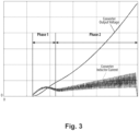
Fig. 3 is a normalized graph of voltage and current versus time for converter output voltage and converter inductor current; and -
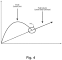
Fig. 4 is normalized graph of the soft start function, showing the inrush current limit and the peak inductor current ramp command as a function of time. - TABLE 1 shows the logic states for the set/reset logic components of
Fig. 2 . - Reference will now be made to the drawings wherein like reference numerals identify similar structural features or aspects of the subject disclosure. For purposes of explanation and illustration, and not limitation, a partial view of an embodiment of a system in accordance with the disclosure is shown in
Fig. 1 and is designated generally byreference character 100. Other embodiments of systems in accordance with the disclosure, or aspects thereof, are provided inFigs. 2-4 and TABLE 1, as will be described. The systems and methods described herein can be used to provide a soft start mode for synchronous/standard buck power converters with wide input voltage ranges, e.g. where the input voltage ranges from 90VDC to 600VDC. - The DC-
DC conversion system 100 includes abuck converter 102 configured to receive a DC link voltage as input and to output a DC output voltage that is lower than the DC link voltage. Acontroller 104 is operatively connected to thebuck converter 102 to control thebuck converter 102. Thecontroller 104 includes logic configured to control thebuck converter 102 in a normal switching mode in response to the DC link voltage being below a predetermined high threshold. Thecontroller 104 also includes logic configured to control thebuck converter 102 in a rate limited switching mode in response to the DC link voltage being at or above the predetermined high threshold. - The
buck converter 102 includes a positive DClink voltage node 106 and a negative DClink voltage node 108. Aswitching component 110 connects the positive and negative DClink voltage nodes controller 104 is operatively connected to control switching of theswitching component 110. Theswitching component 110 includes a pair of switches Q1 and Q2 connected in series across the positive and negative DClink voltage nodes controller 104 so thecontroller 104 can control the switching of the switching components to produce the output voltage at theDC output nodes - The
buck converter 102 includes a main inductor LB connecting a node 112 between the two switches Q1 and Q2 to a positiveDC output node 114. A first reluctance indicated with a dashed box inFig. 1 includes the main inductor LB, wherein RB is the coil resistance of the main inductor LB. A second reluctance (the capacitor CO and its associated internal resistance, RCoesr as indicated by a dashed line box around them inFig. 1 ) is connected across the positiveDC output node 114 and the negative DClink voltage node 108, which is configured to serve as a negative DC output node. The second reluctance is connected in parallel with the load (represented inFig. 1 by RL). Those skilled in the art will readily appreciate that the load is not necessarily part of thebuck converter 102, and can be any suitable load to be powered by the output voltage and current of thecuck converter 102. An input capacitor Cin connects between the positive and negative DClink voltage nodes switching component 110. - While shown and described with a buck converter 100 (in
Fig. 1 ) that is a synchronous buck converter, those skilled in the art will readily appreciate that the second switch Q2 can be changed to a diode, pointed upward as oriented inFig. 1 , to make a standard buck converter which can operate using similar methods as disclosed herein without departing from the scope of this disclosure. - A first current sensor CT2 is operatively connected to provide input indicative of current through the positive
DC output node 114 to a soft startfunction logic component 116 of the controller. A second current sensor CT1 is operatively connected to provide input indicative of current through the positive DC link voltage node to a currentcontrol logic component 118 of thecontroller 104. The currentcontrol logic component 118 is operatively connected to control switching of theswitching component 110. - A first voltage sensor Vo is operatively connected to provide input indicative of voltage across the positive
DC output node 114 and the negative DClink voltage node 108 to thecontroller 104. Asecond voltage sensor 120 is operatively connected to provide input indicative of voltage across the positive and negative DClink voltage nodes controller 104. - A
differential logic component 122 is operatively connected to output a differential signal (VERROR inFig. 1 ) indicative of difference between the input from the first voltage sensor Vo and a commanded output voltage VCMD to a voltageregulation logic component 124 configured to output a voltage control signal (ILB_PK_CMD inFig. 1 ) based on the differential signal VERROR. The control algorithm insideblock 124 can be a standard control algorithm, i.e. a proportional plus integral, although any other suitable type of control algorithm can be used. Aswitch logic component 126 is operatively connected to receive input from the soft start function logic component 116 (iLB_PK_RAMP inFig. 1 ) and from the voltage control logic component 124 (iLB_PK_CMD). The switch logic component is configured to switch between sending output from the soft startfunction logic component 116 or from the voltageregulation logic component 124 to the currentcontrol logic component 118. The soft startfunction logic component 116 is operatively connected to receive input from thesecond voltage sensor 120, and to control theswitch logic component 126 between the soft start switching mode and the normal switching mode. The softstart function logic 116 includes arate limiter 128 operatively connected to output a rate limiting signal (iLB_PK_RAMP) to thecurrent control logic 118. - With continued reference to
Fig. 1 , a method of DC-DC power conversion includes converting a DC link voltage to a DC output voltage for a load that is lower than the DC link voltage using a buck converter,e.g. buck converter 102. The method includes controlling the buck converter in a normal switching mode in response to the DC link voltage, e.g. at the voltage sensor 120) being below a predetermined high threshold. The method also includes controlling the buck converter in a soft start switching mode in response to the DC link voltage being at or above the predetermined high threshold. - With reference now to
Fig. 2 , controlling the buck converter in the soft start switching mode includes latching the soft start switching mode in an enabled state (SS_ON =1 inFigs. 1 and2 ) upon occurrence of enablement (VR_Enable=1 inFigs. 1 and2 ) of voltage regulation in the buck converter, the DC link voltage (atvoltage sensor 120 inFig. 1 ) being at or above the predetermined high threshold (DC LINK VOLTAGE >=DC_LINK_SS_LIMIT=1 inFig. 2 ), to keep the rate limited switching mode enabled even if the DC link voltage drops below the predetermined high threshold after latching. The third enablement requirement for enablement of the soft start switching mode is the DC output voltage (at VOUT inFig. 1 ) being at or below a predetermined initial soft start voltage limit (VOUT <= VOUT_SS_LIMIT_INT inFig. 2 ). The three aforementioned conditions are inputs for a first AND gate 130. If the inputs to the first AND gate 130 are all 1, then the SS_EN condition ofFig. 1 is set to 1. The output of the first AND gate 130 is an input to the second ANDgate 132. - With continued reference now to
Fig. 2 , there are two additional inputs to the second ANDgate 132. First is latching the soft start switching mode in an enabled state upon occurrence of the DC output voltage not being at or above a predetermined final soft start voltage (VOUT>=VOUT_SS_LIMIT_FINAL), note thelogic inverter 134 inverts the VOUT>=VOUT_SS_LIMIT_FINAL condition between the set/reset logic 136c and the second ANDgate 132. The second additional input is occurrence of the load current not being at or above a predetermined soft start current limit (i_Load>=I_LOAD_SS_LIMIT), note the logic inveter 138 inverts the i_Load>=I_LOAD_SS_LIMIT condition between the set/reset logic 136d and the second ANDgate 132. If all of the inputs to the second ANDgate 132 are 1, then the output of the second ANDgate 132, namely SS_ON inFigs. 1 and2 , is 1 enabling the soft start mode, enabling therate limiter 128 as input for the currentcontrol logic component 118. - The method can include resetting the enabled state of the soft start switching mode upon disabling of voltage regulation in the buck converter. In
Fig. 2 , the set/reset logic boxes 136a-d are reset when the VR_Enable is set to 0. TABLE 1 provides the logic for the S and R inputs for the set/reset logic boxes 136a-d, and the corresponding outputs. - With continued reference to
Fig. 2 , SS_ON is an input to the voltageregulation logic component 124 ofFig. 1 . When SS_ON is set to 1 as output from the first AND gate 130, the voltage regulation logic component is held in reset (Verror = 0, PI controller or any other type of integration states are held to zero). SS_ON is an input to theswitch logic component 126 ofFig. 1 and to the currentcontrol logic component 118. When SS_ON =1, The IPK_RAMP_CMD is selected (in the switch logic component 126) and the pulse width modulation (PWM) frequency is reduced for the first switch Q1 and the slower switch Q2 is disabled by the current control logic component 118). - With reference again to
Fig. 1 , controlling the buck converter in the normal switching mode includes controlling current to the load based on measured current supplied to the buck converter at the DC Link Voltage, e.g. as measured by CT1, and a commanded inductor current, e.g. iLB_PK_CMD inFig. 1 , for controlling current in a main inductor, e.g. LB, of the buck converter. The commanded inductor current, iLB_PK_CMD, for controlling the current in the main inductor is derived from a voltage regulation control signal that is based on a differential of commanded output voltage and measured output voltage to the load, e.g. the voltageregulation logic component 124 outputs the ILB_PK_CMD based on input received from thedifferential logic component 122. - Controlling the buck converter in the soft start switching mode includes controlling current to the load based on measured current supplied to the load, , e.g. as measured by the current sensor CT2, also based on measured current supplied to the buck converter at the DC Link Voltage, e.g. as measured by current sensor CT1, and a commanded peak inductor ramp command, e.g. iLB_PK_RAMP, for controlling current in a main inductor of the buck converter. The soft start switching mode includes reducing switching frequency in one switch, e.g. switch Q1, of the buck converter and disabling a second switch, e.g. switch Q2, of the buck converter.
- With reference now to
Fig. 3 , the two phases of the soft start mode are shown graphically where output voltage and inductor current are plotted versus time. In a first phase (Phase 1) the voltageregulation logic component 124 ofFig. 1 is set in reset (hold all states to zero as described above). This limits inrush current by reducing switching frequency and starts inductor peak current ramp, e.g. using therate limiter 128 ofFigs. 1 and2 . In the second phase (Phase 2) the softstart logic component 116 ofFig. 1 continues to ramp the inductor peak current command (iLB_PK_RAMP inFig. 1 ) until output voltage (sensed by VOUT) or load current thresholds (i_Load >=i_LOAD_SS_LIMIT inFig. 2 , where i_LOAD is measured by the current sensor CT2) are valid. - Reference is now made to
Fig. 4 , where current us plotted versus time. The main inductor LB (shown inFig. 1 ) is operated in peak inductor current mode. During the start of the soft start function the buck converter output is initially set to zero and therefore the inductor volts-sec product is unable to keep balanced over a switching cycle. The Inductor volt-sec VL is defined as:
Fig. 1 , and Toff is the off time for the upper switch Q1. The change in inductor current di is defined by:

Fig. 1 , and Vout is close to zero during initial turn-on. To limit the initial in-rush inductor current the switching frequency is reduced by 1/3, which is application dependent. Thiscircle 140 inFig. 4 indicates where the inrush current and peak inductor current rate command intersect to provide a smooth output voltage ramp. - Systems and method disclosed herein provide potential benefits including the following. It is possible to avoid a large overvoltage on the load that is otherwise possible if the buck converter is not soft started. The large overvoltage would otherwise also loads input capacitor (Cin in
Fig. 1 ), so with systems and methods as disclosed herein a smaller input capacitor can be used than in systems without a soft start mode. - As will be appreciated by those skilled in the art, aspects of the present embodiments may be embodied as a system, method or computer program product. Accordingly, aspects of the present embodiments may take the form of an entirely hardware embodiment, an entirely software embodiment (including firmware, resident software, micro-code, etc.) or an embodiment combining software and hardware aspects that may all generally be referred to herein as a "circuit," "module," "component" or "system." Furthermore, aspects of the present disclosure may take the form of a computer program product embodied in one or more computer readable medium(s) having computer readable program code embodied thereon.
- Any combination of one or more computer readable medium(s) may be utilized. The computer readable medium may be a computer readable signal medium or a computer readable storage medium. A computer readable storage medium may be, for example, but not limited to, an electronic, magnetic, optical, electromagnetic, infrared, or semiconductor system, apparatus, or device, or any suitable combination of the foregoing. More specific examples (a non-exhaustive list) of the computer readable storage medium would include the following: an electrical connection having one or more wires, a portable computer diskette, a hard disk, a random access memory (RAM), a read-only memory (ROM), an erasable programmable read-only memory (EPROM or Flash memory), an optical fiber, a portable compact disc read-only memory (CD-ROM), an optical storage device, a magnetic storage device, or any suitable combination of the foregoing. In the context of this document, a computer readable storage medium may be any tangible medium that can contain, or store a program for use by or in connection with an instruction execution system, apparatus, or device.
- A computer readable signal medium may include a propagated data signal with computer readable program code embodied therein, for example, in baseband or as part of a carrier wave. Such a propagated signal may take any of a variety of forms, including, but not limited to, electro-magnetic, optical, or any suitable combination thereof. A computer readable signal medium may be any computer readable medium that is not a computer readable storage medium and that can communicate, propagate, or transport a program for use by or in connection with an instruction execution system, apparatus, or device.
- Program code embodied on a computer readable medium may be transmitted using any appropriate medium, including but not limited to wireless, wireline, optical fiber cable, RF, etc., or any suitable combination of the foregoing.
- Computer program code for carrying out operations for aspects of the present disclosure may be written in any combination of one or more programming languages, including an object oriented programming language such as Java, Smalltalk, C++ or the like and conventional procedural programming languages, such as the "C" programming language or similar programming languages. The program code may execute entirely on the user's computer, partly on the user's computer, as a stand-alone software package, partly on the user's computer and partly on a remote computer or entirely on the remote computer or server. In the latter scenario, the remote computer may be connected to the user's computer through any type of network, including a local area network (LAN) or a wide area network (WAN), or the connection may be made to an external computer (for example, through the Internet using an Internet Service Provider).
- Aspects of the present disclosure are described above with reference to flowchart illustrations and/or block diagrams of methods, apparatus (systems) and computer program products according to embodiments of the embodiments. It will be understood that each block of the flowchart illustrations and/or block diagrams, and combinations of blocks in the flowchart illustrations and/or block diagrams, can be implemented by computer program instructions. These computer program instructions may be provided to a processor of a general purpose computer, special purpose computer, or other programmable data processing apparatus to produce a machine, such that the instructions, which execute via the processor of the computer or other programmable data processing apparatus, create means for implementing the functions/acts specified in the flowchart and/or block diagram block or blocks.
- These computer program instructions may also be stored in a computer readable medium that can direct a computer, other programmable data processing apparatus, or other devices to function in a particular manner, such that the instructions stored in the computer readable medium produce an article of manufacture including instructions which implement the function/act specified in the flowchart and/or block diagram block or blocks.
- The computer program instructions may also be loaded onto a computer, other programmable data processing apparatus, or other devices to cause a series of operational steps to be performed on the computer, other programmable apparatus or other devices to produce a computer implemented process such that the instructions which execute on the computer or other programmable apparatus provide processes for implementing the functions/acts specified in a flowchart and/or block diagram block or blocks.
- The methods and systems of the present disclosure, as described above and shown in the drawings, provide for a soft start mode for synchronous/standard buck power converters with wide input voltage ranges, e.g. where the input voltage ranges from 90VDC to 600VDC. While the apparatus and methods of the subject disclosure have been shown and described with reference to preferred embodiments, those skilled in the art will readily appreciate that changes and/or modifications may be made thereto without departing from the scope of the subject disclosure.
Claims (15)
- A method of DC-DC power conversion comprising:converting a DC link voltage to a DC output voltage for a load that is lower than the DC link voltage using a buck converter (102);controlling the buck converter in a normal switching mode in response to the DC link voltage being below a predetermined high threshold; andcontrolling the buck converter in a soft start switching mode in response to the DC link voltage being at or above the predetermined high threshold.
- The method as recited in claim 1, wherein controlling the buck converter (102) in the soft start switching mode includes latching the soft start switching mode in an enabled state upon occurrence of:enablement of voltage regulation in the buck converter;the DC link voltage being at or above the predetermined high threshold, to keep the rate limited switching mode enabled even if the DC link voltage drops below the predetermined high threshold after latching; andthe DC output voltage being at or below a predetermined initial soft start voltage limit.
- The method as recited in claim 1 or 2, wherein controlling the buck boost converter (102) in the soft start switching mode includes latching the soft start switching mode in an enabled state upon occurrence of:the DC output voltage being at or above a predetermined final soft start voltage; andload current being at or above a predetermined soft start current limit.
- The method as recited in any of claims 1 to 3, further comprising:
resetting the enabled state of the soft start switching mode upon disabling of voltage regulation in the buck converter (102). - The method as recited in any preceding claim, wherein controlling the buck converter (102) in the normal switching mode includes controlling current to the load based on:measured current supplied to the buck converter at the DC Link Voltage, anda commanded inductor current for controlling current in a main inductor (LB) of the buck converter.
- The method as recited in claim 5, wherein the commanded inductor current for controlling the current in the main inductor (LB) is derived from a voltage regulation control signal that is based on a differential of commanded output voltage and measured output voltage to the load.
- The method as recited in any preceding claim , wherein controlling the buck converter (102) in the soft start switching mode includes controlling current to the load based on:measured current supplied to the load,measured current supplied to the buck converter at the DC Link Voltage, anda commanded peak inductor ramp command for controlling current in a main inductor (LB) of the buck converter.
- The method as recited in claim 7, wherein the soft start switching mode includes reducing switching frequency in one switch of the buck converter (102) and disabling a second switch (Q2) of the buck converter.
- A DC-DC conversion system (100) comprising:a buck converter (102) configured to receive a DC link voltage as input and to output a DC output voltage that is lower than the DC link voltage; anda controller (104) operatively connected to the buck converter to control the buck converter, wherein the controller includes logic configured to:control the buck converter in a normal switching mode in response to the DC link voltage being below a predetermined high threshold; andcontrol the buck converter in a soft start switching mode in response to the DC link voltage being at or above the predetermined high threshold.
- The system as recited in claim 9, wherein the buck converter (102) includes a positive DC link voltage node (106) and a negative DC link voltage node (108), with a switching component (110) connecting the positive and negative DC link voltage nodes, wherein the controller (104) is operatively connected to control switching of the switching component.
- The system as recited in claim 10, wherein the switching component (110) includes a pair of switches (Q1, Q2) connected in series, wherein the buck converter includes a main inductor (LB) connecting a node (112) between the two switches to a positive DC output node (114).
- The system as recited in claim 11, further comprising:a first reluctance, an inductor winding resistance of the main inductor (LB);a second reluctance connected in series between the positive DC output node and the negative DC link voltage node (108), wherein the negative DC link voltage node is configured to serve as a negative DC output node; andan input capacitor (Cin) connecting between the positive and negative DC link voltage nodes in parallel with the switching component.
- The system as recited in claim 12, further comprising:a first current sensor (CT2) operatively connected to provide input indicative of current through the positive DC output node (114) to a soft start function logic component (116) of the controller (104); anda second current sensor (CT1) operatively connected to provide input indicative of current through the positive DC link voltage node (114) to a current control logic component of the controller, wherein the current control logic component is operatively connected to control switching of the switching component.
- The system as recited in claim 13, further comprising:a first voltage sensor (Vo) operatively connected to provide input indicative of voltage across the positive DC output node (114) and the negative DC link voltage node (108) to the controller; anda second voltage sensor (120) operatively connected to provide input indicative of voltage across the positive and negative DC link voltage nodes to the controller.
- The system as recited in claim 14, further comprising:a differential logic component (122) operatively connected to output a differential signal (VERROR) indicative of difference between the input from the first voltage sensor (Vo) and a commanded output voltage to a voltage regulation logic component (124) configured to output a voltage control signal based on the differential signal;a switch logic component (126) operatively connected to receive input from the soft start function logic component (116) and from the voltage control logic component (124), wherein the switch logic component is configured to switch between sending output from the soft start function logic component or from the voltage regulation logic component to the current control logic component; andwherein the soft start function logic component (116) is operatively connected to receive input from the second voltage sensor (120), and to control the switch logic component between the soft start switching mode and the normal switching mode, and wherein the soft start function logic includes a rate limiter operatively connected to output a rate limiting signal to the current control logic.
Applications Claiming Priority (1)
| Application Number | Priority Date | Filing Date | Title |
|---|---|---|---|
| US17/717,776 US12294299B2 (en) | 2022-04-11 | 2022-04-11 | Soft start for buck converters |
Publications (1)
| Publication Number | Publication Date |
|---|---|
| EP4262074A1 true EP4262074A1 (en) | 2023-10-18 |
Family
ID=86006539
Family Applications (1)
| Application Number | Title | Priority Date | Filing Date |
|---|---|---|---|
| EP23167425.0A Pending EP4262074A1 (en) | 2022-04-11 | 2023-04-11 | Soft start for buck converters |
Country Status (2)
| Country | Link |
|---|---|
| US (1) | US12294299B2 (en) |
| EP (1) | EP4262074A1 (en) |
Citations (8)
| Publication number | Priority date | Publication date | Assignee | Title |
|---|---|---|---|---|
| US20040174144A1 (en) * | 2003-03-03 | 2004-09-09 | Hong Huang | Synchronous rectifier back bias control circuit |
| US20090302816A1 (en) * | 2008-06-10 | 2009-12-10 | Panasonic Corporation | Switching power supply and semiconductor device used for the same |
| US8120342B1 (en) * | 2008-05-06 | 2012-02-21 | Volterra Semiconductor Corporation | Current report in current mode switching regulation |
| US20140292292A1 (en) * | 2013-04-01 | 2014-10-02 | Qualcomm Incorporated | Voltage regulator over-current protection |
| US20160380537A1 (en) * | 2015-06-24 | 2016-12-29 | Infineon Technologies Ag | System and Method for Starting a Switched-Mode Power Supply |
| US20170070149A1 (en) * | 2015-09-08 | 2017-03-09 | Rohm Co., Ltd. | Dc/dc converter and switching power supply |
| US20180006560A1 (en) * | 2016-07-01 | 2018-01-04 | Infineon Technologies Austria Ag | Method and apparatus for limiting inrush current during startup of a buck converter |
| US20220103069A1 (en) * | 2020-09-30 | 2022-03-31 | Audiowise Technology Inc. | Soft-start method for a switching regulator |
Family Cites Families (18)
| Publication number | Priority date | Publication date | Assignee | Title |
|---|---|---|---|---|
| US7023187B2 (en) * | 2001-08-16 | 2006-04-04 | Intersil Americas Inc. | Integrated circuit for generating a plurality of direct current (DC) output voltages |
| US6933710B2 (en) | 2002-02-19 | 2005-08-23 | Fairchild Semiconductor Corporation | Soft start techniques for control loops that regulate DC/DC converters |
| US7038514B2 (en) * | 2003-10-28 | 2006-05-02 | Intersil Americas Inc. | Startup circuit for a DC-DC converter |
| US7034586B2 (en) * | 2004-03-05 | 2006-04-25 | Intersil Americas Inc. | Startup circuit for converter with pre-biased load |
| US7518885B2 (en) | 2006-10-04 | 2009-04-14 | Power Integrations, Inc. | Method and apparatus for a control circuit with multiple operation modes |
| JP5211959B2 (en) | 2008-09-12 | 2013-06-12 | 株式会社リコー | DC-DC converter |
| JP2011067025A (en) | 2009-09-17 | 2011-03-31 | Seiko Instruments Inc | Dc-dc converter |
| JP5477699B2 (en) * | 2009-09-30 | 2014-04-23 | サンケン電気株式会社 | Switching power supply |
| KR102045780B1 (en) * | 2013-03-05 | 2019-11-18 | 삼성전자주식회사 | Bidirectional voltage positioning circuit, voltage converter and power supply device including the same |
| KR20170002327A (en) | 2015-06-29 | 2017-01-06 | 페어차일드코리아반도체 주식회사 | Input voltage detecting circuit and power supply device comprising the same |
| US9705408B2 (en) * | 2015-08-21 | 2017-07-11 | Microchip Technology Incorporated | Power converter with sleep/wake mode |
| US10044271B1 (en) * | 2017-04-28 | 2018-08-07 | Texas Instruments Incorporated | Methods and apparatus for DC-DC soft start |
| US10396654B2 (en) * | 2017-10-25 | 2019-08-27 | Schneider Electric Solar Inverters Usa, Inc. | Start-up circuit |
| US10199928B1 (en) * | 2018-01-19 | 2019-02-05 | Infineon Technologies Austria Ag | Soft start of switched capacitor converters by reducing voltage provided by initial power switch |
| US10622897B2 (en) | 2018-09-17 | 2020-04-14 | Hamilton Sundstrand Corporation | Controller for buck DC/DC converter with effective decoupling |
| US11411497B2 (en) * | 2020-08-18 | 2022-08-09 | Nxp Usa, Inc. | Switching power regulator and method for recovering the switching power regulator from an unregulated state |
| CN113489318A (en) | 2021-06-09 | 2021-10-08 | 西安理工大学 | Method for controlling working mode of Buck converter |
| US12068692B2 (en) * | 2021-12-15 | 2024-08-20 | Raytheon Company | Multi slope output impedance controller to reduce current imbalance in a masterless configuration of n parallel-connected power converters and improve load regulation in a single power converter |
-
2022
- 2022-04-11 US US17/717,776 patent/US12294299B2/en active Active
-
2023
- 2023-04-11 EP EP23167425.0A patent/EP4262074A1/en active Pending
Patent Citations (8)
| Publication number | Priority date | Publication date | Assignee | Title |
|---|---|---|---|---|
| US20040174144A1 (en) * | 2003-03-03 | 2004-09-09 | Hong Huang | Synchronous rectifier back bias control circuit |
| US8120342B1 (en) * | 2008-05-06 | 2012-02-21 | Volterra Semiconductor Corporation | Current report in current mode switching regulation |
| US20090302816A1 (en) * | 2008-06-10 | 2009-12-10 | Panasonic Corporation | Switching power supply and semiconductor device used for the same |
| US20140292292A1 (en) * | 2013-04-01 | 2014-10-02 | Qualcomm Incorporated | Voltage regulator over-current protection |
| US20160380537A1 (en) * | 2015-06-24 | 2016-12-29 | Infineon Technologies Ag | System and Method for Starting a Switched-Mode Power Supply |
| US20170070149A1 (en) * | 2015-09-08 | 2017-03-09 | Rohm Co., Ltd. | Dc/dc converter and switching power supply |
| US20180006560A1 (en) * | 2016-07-01 | 2018-01-04 | Infineon Technologies Austria Ag | Method and apparatus for limiting inrush current during startup of a buck converter |
| US20220103069A1 (en) * | 2020-09-30 | 2022-03-31 | Audiowise Technology Inc. | Soft-start method for a switching regulator |
Also Published As
| Publication number | Publication date |
|---|---|
| US20230327550A1 (en) | 2023-10-12 |
| US12294299B2 (en) | 2025-05-06 |
Similar Documents
| Publication | Publication Date | Title |
|---|---|---|
| US6118675A (en) | Method and apparatus for controlling power transfer in a flyback converter by modulating the power switch off time during transient conditions | |
| CN102263508B (en) | Resonant conversion system and overcurrent protection method | |
| CN103081321B (en) | Buck Switch Mode Power Converter Large Signal Transient Response Optimizer | |
| EP2365622B1 (en) | Method and circuit for controlling a switched-mode power converter with fast transient response | |
| EP3506478A1 (en) | Power circuit, power circuit control method, and storage medium | |
| WO2015090236A1 (en) | Integrated circuit for controlling switch power supply and switch power supply | |
| US10615636B2 (en) | Uninterruptible power supply | |
| US9559604B2 (en) | DC/DC converter and control method of DC/DC converter | |
| EP3010130B1 (en) | Switch rectifier startup control method, and device and storage medium thereof | |
| WO2019116722A1 (en) | Power conversion device | |
| WO2024164670A1 (en) | Soft start control method and apparatus for energy storage direct-current converter, and energy storage system | |
| JP5549942B2 (en) | DCDC converter | |
| US12294299B2 (en) | Soft start for buck converters | |
| AU2012364266B2 (en) | Power converter with digital current control circuit | |
| CN111740610B (en) | Input voltage feedforward circuit, input voltage feedforward control method and device | |
| EP4277100A1 (en) | Buck converters with light load function and logic | |
| US12278588B2 (en) | Method and apparatus for controlling output power of generator, and generator system | |
| CN119765433A (en) | Converter architecture, control method, battery pack and energy storage system | |
| JP2021002927A (en) | Controller of power conversion circuit | |
| EP4262070A1 (en) | Peak current change rate limiting for buck converters | |
| JP7034230B1 (en) | Power converter | |
| US20230369975A1 (en) | High voltage dc-dc converters | |
| US12614985B2 (en) | LLC converter, control circuit, soft start method, apparatus, and chip | |
| JP7341177B2 (en) | power converter | |
| US20250141349A1 (en) | Three-phase resonant dc-dc converter |
Legal Events
| Date | Code | Title | Description |
|---|---|---|---|
| PUAI | Public reference made under article 153(3) epc to a published international application that has entered the european phase |
Free format text: ORIGINAL CODE: 0009012 |
|
| STAA | Information on the status of an ep patent application or granted ep patent |
Free format text: STATUS: THE APPLICATION HAS BEEN PUBLISHED |
|
| AK | Designated contracting states |
Kind code of ref document: A1 Designated state(s): AL AT BE BG CH CY CZ DE DK EE ES FI FR GB GR HR HU IE IS IT LI LT LU LV MC ME MK MT NL NO PL PT RO RS SE SI SK SM TR |
|
| STAA | Information on the status of an ep patent application or granted ep patent |
Free format text: STATUS: REQUEST FOR EXAMINATION WAS MADE |
|
| 17P | Request for examination filed |
Effective date: 20240410 |
|
| RBV | Designated contracting states (corrected) |
Designated state(s): AL AT BE BG CH CY CZ DE DK EE ES FI FR GB GR HR HU IE IS IT LI LT LU LV MC ME MK MT NL NO PL PT RO RS SE SI SK SM TR |