EP4261979A2 - Battery pack and method for disassembling battery pack - Google Patents
Battery pack and method for disassembling battery pack Download PDFInfo
- Publication number
- EP4261979A2 EP4261979A2 EP22206828.0A EP22206828A EP4261979A2 EP 4261979 A2 EP4261979 A2 EP 4261979A2 EP 22206828 A EP22206828 A EP 22206828A EP 4261979 A2 EP4261979 A2 EP 4261979A2
- Authority
- EP
- European Patent Office
- Prior art keywords
- battery
- connector
- frame
- battery pack
- box
- Prior art date
- Legal status (The legal status is an assumption and is not a legal conclusion. Google has not performed a legal analysis and makes no representation as to the accuracy of the status listed.)
- Withdrawn
Links
- 238000000034 method Methods 0.000 title claims abstract description 28
- 230000000903 blocking effect Effects 0.000 claims abstract description 6
- 238000005192 partition Methods 0.000 claims description 34
- 230000003014 reinforcing effect Effects 0.000 claims description 10
- 230000000717 retained effect Effects 0.000 claims description 3
- 238000012423 maintenance Methods 0.000 description 15
- 239000000853 adhesive Substances 0.000 description 7
- 230000001070 adhesive effect Effects 0.000 description 7
- 230000008569 process Effects 0.000 description 5
- 238000010079 rubber tapping Methods 0.000 description 4
- 230000017525 heat dissipation Effects 0.000 description 3
- 230000006978 adaptation Effects 0.000 description 2
- 238000001816 cooling Methods 0.000 description 2
- 239000007788 liquid Substances 0.000 description 2
- 239000012782 phase change material Substances 0.000 description 2
- 239000012790 adhesive layer Substances 0.000 description 1
- 238000003487 electrochemical reaction Methods 0.000 description 1
- 239000003792 electrolyte Substances 0.000 description 1
- 238000010030 laminating Methods 0.000 description 1
- 230000007246 mechanism Effects 0.000 description 1
- 238000012986 modification Methods 0.000 description 1
- 230000004048 modification Effects 0.000 description 1
- 230000002787 reinforcement Effects 0.000 description 1
- 230000008439 repair process Effects 0.000 description 1
- 238000007789 sealing Methods 0.000 description 1
- 238000004804 winding Methods 0.000 description 1
Images




Classifications
-
- H—ELECTRICITY
- H01—ELECTRIC ELEMENTS
- H01M—PROCESSES OR MEANS, e.g. BATTERIES, FOR THE DIRECT CONVERSION OF CHEMICAL ENERGY INTO ELECTRICAL ENERGY
- H01M10/00—Secondary cells; Manufacture thereof
- H01M10/04—Construction or manufacture in general
-
- H—ELECTRICITY
- H01—ELECTRIC ELEMENTS
- H01M—PROCESSES OR MEANS, e.g. BATTERIES, FOR THE DIRECT CONVERSION OF CHEMICAL ENERGY INTO ELECTRICAL ENERGY
- H01M50/00—Constructional details or processes of manufacture of the non-active parts of electrochemical cells other than fuel cells, e.g. hybrid cells
- H01M50/20—Mountings; Secondary casings or frames; Racks, modules or packs; Suspension devices; Shock absorbers; Transport or carrying devices; Holders
- H01M50/262—Mountings; Secondary casings or frames; Racks, modules or packs; Suspension devices; Shock absorbers; Transport or carrying devices; Holders with fastening means, e.g. locks
- H01M50/264—Mountings; Secondary casings or frames; Racks, modules or packs; Suspension devices; Shock absorbers; Transport or carrying devices; Holders with fastening means, e.g. locks for cells or batteries, e.g. straps, tie rods or peripheral frames
-
- H—ELECTRICITY
- H01—ELECTRIC ELEMENTS
- H01M—PROCESSES OR MEANS, e.g. BATTERIES, FOR THE DIRECT CONVERSION OF CHEMICAL ENERGY INTO ELECTRICAL ENERGY
- H01M50/00—Constructional details or processes of manufacture of the non-active parts of electrochemical cells other than fuel cells, e.g. hybrid cells
- H01M50/20—Mountings; Secondary casings or frames; Racks, modules or packs; Suspension devices; Shock absorbers; Transport or carrying devices; Holders
- H01M50/204—Racks, modules or packs for multiple batteries or multiple cells
-
- H—ELECTRICITY
- H01—ELECTRIC ELEMENTS
- H01M—PROCESSES OR MEANS, e.g. BATTERIES, FOR THE DIRECT CONVERSION OF CHEMICAL ENERGY INTO ELECTRICAL ENERGY
- H01M10/00—Secondary cells; Manufacture thereof
- H01M10/42—Methods or arrangements for servicing or maintenance of secondary cells or secondary half-cells
-
- H—ELECTRICITY
- H01—ELECTRIC ELEMENTS
- H01M—PROCESSES OR MEANS, e.g. BATTERIES, FOR THE DIRECT CONVERSION OF CHEMICAL ENERGY INTO ELECTRICAL ENERGY
- H01M10/00—Secondary cells; Manufacture thereof
- H01M10/54—Reclaiming serviceable parts of waste accumulators
-
- H—ELECTRICITY
- H01—ELECTRIC ELEMENTS
- H01M—PROCESSES OR MEANS, e.g. BATTERIES, FOR THE DIRECT CONVERSION OF CHEMICAL ENERGY INTO ELECTRICAL ENERGY
- H01M10/00—Secondary cells; Manufacture thereof
- H01M10/60—Heating or cooling; Temperature control
- H01M10/65—Means for temperature control structurally associated with the cells
- H01M10/655—Solid structures for heat exchange or heat conduction
- H01M10/6554—Rods or plates
-
- H—ELECTRICITY
- H01—ELECTRIC ELEMENTS
- H01M—PROCESSES OR MEANS, e.g. BATTERIES, FOR THE DIRECT CONVERSION OF CHEMICAL ENERGY INTO ELECTRICAL ENERGY
- H01M10/00—Secondary cells; Manufacture thereof
- H01M10/60—Heating or cooling; Temperature control
- H01M10/65—Means for temperature control structurally associated with the cells
- H01M10/655—Solid structures for heat exchange or heat conduction
- H01M10/6556—Solid parts with flow channel passages or pipes for heat exchange
-
- H—ELECTRICITY
- H01—ELECTRIC ELEMENTS
- H01M—PROCESSES OR MEANS, e.g. BATTERIES, FOR THE DIRECT CONVERSION OF CHEMICAL ENERGY INTO ELECTRICAL ENERGY
- H01M50/00—Constructional details or processes of manufacture of the non-active parts of electrochemical cells other than fuel cells, e.g. hybrid cells
- H01M50/20—Mountings; Secondary casings or frames; Racks, modules or packs; Suspension devices; Shock absorbers; Transport or carrying devices; Holders
- H01M50/204—Racks, modules or packs for multiple batteries or multiple cells
- H01M50/207—Racks, modules or packs for multiple batteries or multiple cells characterised by their shape
- H01M50/209—Racks, modules or packs for multiple batteries or multiple cells characterised by their shape adapted for prismatic or rectangular cells
-
- H—ELECTRICITY
- H01—ELECTRIC ELEMENTS
- H01M—PROCESSES OR MEANS, e.g. BATTERIES, FOR THE DIRECT CONVERSION OF CHEMICAL ENERGY INTO ELECTRICAL ENERGY
- H01M50/00—Constructional details or processes of manufacture of the non-active parts of electrochemical cells other than fuel cells, e.g. hybrid cells
- H01M50/20—Mountings; Secondary casings or frames; Racks, modules or packs; Suspension devices; Shock absorbers; Transport or carrying devices; Holders
- H01M50/233—Mountings; Secondary casings or frames; Racks, modules or packs; Suspension devices; Shock absorbers; Transport or carrying devices; Holders characterised by physical properties of casings or racks, e.g. dimensions
- H01M50/242—Mountings; Secondary casings or frames; Racks, modules or packs; Suspension devices; Shock absorbers; Transport or carrying devices; Holders characterised by physical properties of casings or racks, e.g. dimensions adapted for protecting batteries against vibrations, collision impact or swelling
-
- H—ELECTRICITY
- H01—ELECTRIC ELEMENTS
- H01M—PROCESSES OR MEANS, e.g. BATTERIES, FOR THE DIRECT CONVERSION OF CHEMICAL ENERGY INTO ELECTRICAL ENERGY
- H01M50/00—Constructional details or processes of manufacture of the non-active parts of electrochemical cells other than fuel cells, e.g. hybrid cells
- H01M50/20—Mountings; Secondary casings or frames; Racks, modules or packs; Suspension devices; Shock absorbers; Transport or carrying devices; Holders
- H01M50/244—Secondary casings; Racks; Suspension devices; Carrying devices; Holders characterised by their mounting method
-
- H—ELECTRICITY
- H01—ELECTRIC ELEMENTS
- H01M—PROCESSES OR MEANS, e.g. BATTERIES, FOR THE DIRECT CONVERSION OF CHEMICAL ENERGY INTO ELECTRICAL ENERGY
- H01M50/00—Constructional details or processes of manufacture of the non-active parts of electrochemical cells other than fuel cells, e.g. hybrid cells
- H01M50/20—Mountings; Secondary casings or frames; Racks, modules or packs; Suspension devices; Shock absorbers; Transport or carrying devices; Holders
- H01M50/249—Mountings; Secondary casings or frames; Racks, modules or packs; Suspension devices; Shock absorbers; Transport or carrying devices; Holders specially adapted for aircraft or vehicles, e.g. cars or trains
-
- H—ELECTRICITY
- H01—ELECTRIC ELEMENTS
- H01M—PROCESSES OR MEANS, e.g. BATTERIES, FOR THE DIRECT CONVERSION OF CHEMICAL ENERGY INTO ELECTRICAL ENERGY
- H01M50/00—Constructional details or processes of manufacture of the non-active parts of electrochemical cells other than fuel cells, e.g. hybrid cells
- H01M50/20—Mountings; Secondary casings or frames; Racks, modules or packs; Suspension devices; Shock absorbers; Transport or carrying devices; Holders
- H01M50/258—Modular batteries; Casings provided with means for assembling
-
- H—ELECTRICITY
- H01—ELECTRIC ELEMENTS
- H01M—PROCESSES OR MEANS, e.g. BATTERIES, FOR THE DIRECT CONVERSION OF CHEMICAL ENERGY INTO ELECTRICAL ENERGY
- H01M50/00—Constructional details or processes of manufacture of the non-active parts of electrochemical cells other than fuel cells, e.g. hybrid cells
- H01M50/20—Mountings; Secondary casings or frames; Racks, modules or packs; Suspension devices; Shock absorbers; Transport or carrying devices; Holders
- H01M50/262—Mountings; Secondary casings or frames; Racks, modules or packs; Suspension devices; Shock absorbers; Transport or carrying devices; Holders with fastening means, e.g. locks
-
- H—ELECTRICITY
- H01—ELECTRIC ELEMENTS
- H01M—PROCESSES OR MEANS, e.g. BATTERIES, FOR THE DIRECT CONVERSION OF CHEMICAL ENERGY INTO ELECTRICAL ENERGY
- H01M50/00—Constructional details or processes of manufacture of the non-active parts of electrochemical cells other than fuel cells, e.g. hybrid cells
- H01M50/20—Mountings; Secondary casings or frames; Racks, modules or packs; Suspension devices; Shock absorbers; Transport or carrying devices; Holders
- H01M50/271—Lids or covers for the racks or secondary casings
-
- H—ELECTRICITY
- H01—ELECTRIC ELEMENTS
- H01M—PROCESSES OR MEANS, e.g. BATTERIES, FOR THE DIRECT CONVERSION OF CHEMICAL ENERGY INTO ELECTRICAL ENERGY
- H01M6/00—Primary cells; Manufacture thereof
- H01M6/42—Grouping of primary cells into batteries
-
- H—ELECTRICITY
- H01—ELECTRIC ELEMENTS
- H01M—PROCESSES OR MEANS, e.g. BATTERIES, FOR THE DIRECT CONVERSION OF CHEMICAL ENERGY INTO ELECTRICAL ENERGY
- H01M6/00—Primary cells; Manufacture thereof
- H01M6/50—Methods or arrangements for servicing or maintenance, e.g. for maintaining operating temperature
-
- H—ELECTRICITY
- H01—ELECTRIC ELEMENTS
- H01M—PROCESSES OR MEANS, e.g. BATTERIES, FOR THE DIRECT CONVERSION OF CHEMICAL ENERGY INTO ELECTRICAL ENERGY
- H01M2220/00—Batteries for particular applications
- H01M2220/20—Batteries in motive systems, e.g. vehicle, ship, plane
-
- Y—GENERAL TAGGING OF NEW TECHNOLOGICAL DEVELOPMENTS; GENERAL TAGGING OF CROSS-SECTIONAL TECHNOLOGIES SPANNING OVER SEVERAL SECTIONS OF THE IPC; TECHNICAL SUBJECTS COVERED BY FORMER USPC CROSS-REFERENCE ART COLLECTIONS [XRACs] AND DIGESTS
- Y02—TECHNOLOGIES OR APPLICATIONS FOR MITIGATION OR ADAPTATION AGAINST CLIMATE CHANGE
- Y02E—REDUCTION OF GREENHOUSE GAS [GHG] EMISSIONS, RELATED TO ENERGY GENERATION, TRANSMISSION OR DISTRIBUTION
- Y02E60/00—Enabling technologies; Technologies with a potential or indirect contribution to GHG emissions mitigation
- Y02E60/10—Energy storage using batteries
-
- Y—GENERAL TAGGING OF NEW TECHNOLOGICAL DEVELOPMENTS; GENERAL TAGGING OF CROSS-SECTIONAL TECHNOLOGIES SPANNING OVER SEVERAL SECTIONS OF THE IPC; TECHNICAL SUBJECTS COVERED BY FORMER USPC CROSS-REFERENCE ART COLLECTIONS [XRACs] AND DIGESTS
- Y02—TECHNOLOGIES OR APPLICATIONS FOR MITIGATION OR ADAPTATION AGAINST CLIMATE CHANGE
- Y02W—CLIMATE CHANGE MITIGATION TECHNOLOGIES RELATED TO WASTEWATER TREATMENT OR WASTE MANAGEMENT
- Y02W30/00—Technologies for solid waste management
- Y02W30/50—Reuse, recycling or recovery technologies
- Y02W30/84—Recycling of batteries or fuel cells
Definitions
- the present disclosure relates to the technical field of batteries, and in particular, to a battery pack and a method for disassembling the battery pack.
- the present disclosure provides a battery pack and a method for disassembling the battery pack.
- a battery pack includes a battery box, a first connector, a first battery, and a second battery.
- the first connector is detachably disposed in the battery box.
- the first battery is fixed on the first connector to be arranged in the battery box through the first connector.
- the second battery is arranged in the battery box.
- the first connector is not fixedly connected to the second battery to prevent the second battery from blocking the first battery and the first connector from being simultaneously removed from the battery box.
- a method for disassembling a battery pack includes following steps. Disconnecting a first connector from a battery box, and detaching the first connector from the battery box, wherein a first battery is detached simultaneously with the first connector, and a second battery is retained in the battery box.
- connection In particular, a reference to “the” object or “a” and “an” object is intended to denote also one of a possible plurality of such objects.
- the terms “connect”, “fix” should be broadly interpreted, for example, the term “connect” can be “fixedly connect”, “detachably connect”, “integrally connect”, “electrically connect” or “signal connect”.
- the term “connect” also can be “directly connect” or “indirectly connect via a medium”.
- the battery pack includes a battery box 10, a first connector 20, a first battery 30, and a second battery 40.
- the first connector 20 is detachably arranged in the battery box 10.
- the first battery 30 is fixed on the first connector 20, so as to be arranged in the battery box 10 through the first connector 20.
- the second battery 40 is arranged in the battery box 10, and the first connector 20 is not fixedly connected to the second battery 40 to prevent the second battery 40 from blocking the first battery 30 and the first connector 20 from being simultaneously detached from the battery box 10.
- the battery pack in an embodiment of the present disclosure includes the battery box 10, the first connector 20, the first battery 30, and the second battery 40. Both the first battery 30 and the second battery 40 are provided on the battery box 10.
- the first battery 30 is fixed on the first connector 20
- the first connector 20 is detachably arranged on the battery box 10
- the second battery 40 is not fixedly connected to the first connector 20
- the first battery 30 and the first connector 20 may be simultaneously detached from the battery box 10 without affecting the second battery 40, so as to facilitate the maintenance of the battery pack, thereby improving the performance of the battery pack.
- the first battery 30 is fixed on the first connector 20, and the first connector 20 is detachably arranged in the battery box 10, so as to ensure that the first battery 30 is stably arranged in the battery box 10. It is possible to prevent the first battery 30 from shaking during normal use.
- the connection between the first connector 20 and the battery box 10 may be released, so that the first connector 20 may be detached from the battery box 10, and that the first battery 30 may be taken out from the battery box 10, and subsequent maintenance may be performed.
- the first battery 30 on the first connector 20 is detached ⁇ and is replaced with a new first battery 30 to be arranged on the original first connector 20.
- the first battery 30 and the first connector 20 are arranged on the battery box 10.
- the first battery 30 and the first connector 20 are directly replaced with new first battery 30 and new first connector 20, which are then arranged on the battery box 10.
- Neither the first battery 30 nor the first connector 20 may be fixedly connected to the second battery 40, so that when the first battery 30 and the first connector 20 are detached from the battery box 10, the second battery 40 will not obstruct the first battery 30 and the first connector 20. In this manner, it is possible to ensure independent detachment of the first battery 30 and the first connector 20, without affecting the second battery 40.
- a battery includes a cell and an electrolyte, and is the smallest unit capable of performing electrochemical reactions such as charge/discharge.
- the cell refers to a unit formed by winding or laminating a stack portion, and the stack portion includes a first electrode, a separator and a second electrode.
- the first electrode is a positive electrode
- the second electrode is a negative electrode.
- the polarities of the first electrode and the second electrode may be interchanged.
- the second battery 40 may be stably arranged in the battery box 10. Under the circumstances, the second battery 40 may be directly fixed on the battery box 10. Alternatively, the second battery 40 may be fixed on the battery box 10 through other components, the disclosure provides no limitation thereto.
- the first battery 30 is adhesively connected to the first connector 20, so as to ensure that the first battery 30 is stably connected to the first connector 20, and to avoid problem such as shaking of the first battery 30, thereby improving the safety performance of the first battery 30.
- the first battery 30 and the first connector 20 may be bonded by a thermally conductive structural adhesive, which not only may ensure the strength of the connection, but also may realize heat transfer by the thermally conductive structural adhesive, thereby improving the heat dissipation capability of the first battery 30.
- first battery 30 and the first connector 20 may be connected through engagement connection, for example.
- first batteries 30 there are a plurality of first batteries 30, and the plurality of first batteries 30 are all fixed on the first connector 20, so that when the first connector 20 is detached from the battery box 10, the multiple first batteries 30 may be simultaneously detached from the battery box 10 along with the first connector 20.
- the plurality of first batteries 30 may form a battery module 1 and then be fixed on the first connector 20, and specifically, the plurality of first batteries 30 may be fixed through end plates and lateral plates to form the battery module 1, and finally arranged in the battery box 10, as shown in FIG 5 .
- the plurality of first batteries 30 may be independently fixed on the first connector 20, that is, there is no need to group the plurality of first batteries 30. Under the circumstances, the end plate and the lateral plate may be removed.
- the battery pack further includes a second connector 50, and the second connector 50 is detachably arranged in the battery box 10.
- the second battery 40 is fixed on the second connector 50 to be arranged in the battery box 10 through the second connector 50.
- the first battery 30 is not fixedly connected to the second connector 50, so as to prevent the first battery 30 from blocking the second battery 40 and the second connector 50 from being simultaneously detached from the battery box 10. In this manner, when the second battery 40 and the second connector 50 are simultaneously detached from the battery box 10, the detachment will not affect the first battery 30, so as to facilitate the maintenance of the battery pack.
- the first battery 30 may be detachably arranged on the battery box 10 through the first connector 20, and the second battery 40 may be detachably arranged on the battery box 10 through the second connector 50. In this manner, the first battery 30 or the second battery 40 may be independently detached from the battery box 10 according to maintenance requirements, thereby improving maintenance efficiency.
- the second battery 40 is adhesively connected to the second connector 50, such that that the second battery 40 is ensured to be stably connected to the second connector 50, and problem such as shaking of the second battery 40 is avoided, thereby improving the safety performance of the second battery 40.
- the second battery 40 and the second connector 50 may be bonded through the thermally conductive structural adhesive, which not only may ensure the strength of the connection, but also may realize heat transfer through the thermally conductive structural adhesive, thereby improving the heat dissipation capability of the second battery 40.
- the second battery 40 and the second connector 50 may be connected through engagement connection, for example.
- the plurality of second batteries 40 are all fixed on the second connector 50, so that when the second connector 50 is detached from the battery box 10, the plurality of second batteries 40 may be simultaneously detached from the battery box 10 along with the second connector 50.
- the plurality of second batteries 40 may from a battery module and then be fixed on the second connector 50, and specifically, the plurality of second batteries 40 may be fixed through end plates and lateral plates to form the battery module.
- the plurality of second batteries 40 may be independently fixed on the second connector 50, that is, there is no need to group the plurality of second batteries 40. Under the circumstances, the end plate and the lateral plate may be removed.
- first battery 30 and the second battery 40 may be the same type of batteries. In some embodiments, it is not excluded that the first battery 30 and the second battery 40 may be different types of batteries, the disclosure is not limited thereto.
- the plurality of first batteries 30 may be connected in series or in parallel, and the plurality of second batteries 40 may be connected in series or in parallel.
- the plurality of first batteries 30 form a first module
- the plurality of second batteries 40 form a second module
- the first module and the second module may also be electrically connected.
- the connection relationship between the first module and the second module may be disconnected, so as to ensure that the first battery 30 and the second battery 40 do not affect each other.
- the first battery 30 and the second battery 40 are connected through the bus bar, because there is no connection relationship between the second battery 40 and the first connector 20, and there is no connection relationship between the second battery 40 and the second connector 50, when the first battery 30 and the second battery 40 are independently detached, it is only necessary to disconnect the connection relationship between the first battery 30 and the second battery 40, the first battery 30 can be detached along with the first connector 20, or the second battery 40 is detached along with the second connector 50. In this manner, the overall structure of the battery pack may not be damaged.
- first connector 20 and the second connector 50 may be connected, but the first connector 20 and the second connector 50 are detachably connected, the first connector 20 and the second connector 50 may be directly connected, or the first connector 20 and the second connector 50 may be indirectly connected.
- the first connector 20 and the second connector 50 are arranged at intervals, so that when the first connector 20 and the second connector 50 are in independent detachment, it is possible to omit the detachment of the direct connection relationship between the first connector 20 and the second connector 50. In this way, the connection strength between the first connector 20 or the second connector 50 and the battery box 10 may not be affected.
- the first connector 20 includes a circulating flow channel, and the circulating flow channel may be provided with a heat exchange medium, such as a liquid heat exchange medium, a gas exchange medium or a phase change material, etc., so that the heat transfer performance of the first connector 20 may be improved, so as to realize cooling or preheating of the first battery 30.
- a heat exchange medium such as a liquid heat exchange medium, a gas exchange medium or a phase change material, etc.
- the second connector 50 includes a circulating flow channel, and the circulating flow channel may be provided with a heat exchange medium, such as a liquid heat exchange medium, a gas exchange medium or a phase change material, etc., so that the heat transfer performance of the second connector 50 may be improved, so as to realize cooling or preheating of the second battery 40.
- a heat exchange medium such as a liquid heat exchange medium, a gas exchange medium or a phase change material, etc.
- first connector 20 and the second connector 50 form a temperature adjustment mechanism of the battery pack, so as to realize the temperature adjustment of the batteries inside the battery pack, thereby ensuring the use performance of the battery pack.
- the first connector 20 may be a plate-like structure
- the second connector 50 may be a plate-like structure
- the plate-like structure may include upper and lower plates stacked together, so as to form a circulating flow channel between the two plates.
- the specific structural form of the plate-like structure and the specific structural form of the circulating flow channel are not limited in the disclosure, and may be selected according to actual needs.
- the battery box 10 includes a bottom plate 11 and a frame 12.
- the frame 12 is arranged around the bottom plate 11.
- the first connector 20 is arranged in the frame 12, and at least one of the bottom plate 11 and the frame 12 is connected to the first connector 20, so as to ensure that the first connector 20 is stably arranged in the battery box 10.
- At least one of the bottom plate 11 and the frame 12 is detachably connected to the first connector 20, that is, the bottom plate 11 is detachably connected to the first connector 20, and/or the frame 12 is detachably connected to the first connector 20. In this manner, it is also possible to ensure that the first connector 20 may be detached from the battery box 10.
- the second battery 40 is disposed on the battery box 10 through the second connector 50, and at least one of the bottom plate 11 and the frame 12 is detachably connected to the second connector 50.
- the arrangement of the frame 12 around the bottom plate 11 does not mean a specific configuration, and the key point is to explain that the frame 12 forms a circumferentially closed space.
- the frame 12 is connected to the bottom plate 11, and the frame 12 may be disposed on the bottom plate 11, or the frame 12 may be connected to the circumferential edge of the bottom plate 11, the disclosure is not limited thereto.
- the bottom plate 11 and the frame 12 form an accommodating space
- the first connector 20 is arranged in the accommodating space
- the second connector 50 is arranged in the accommodating space, that is, the first battery 30 and the second battery 40 are arranged in the accommodating space.
- the first connector 20 and the second connector 50 may be detached from the bottom plate 11 and the frame 12 independently.
- the first connector 20 and the second connector 50 may be taken out from the top portion of the frame 12, or the first connector 20 and the second connector 50 may be taken out from the bottom portion of the frame 12.
- the frame 12 is detachably connected to the bottom plate 11, and the frame 12 is detachably connected to the first connector 20. That is, during the detachment process of the first connector 20, if the first connector 20 is taken out from the bottom portion of the frame 12, it is necessary to first detach the bottom plate 11 from the frame 12, and then complete the detachment of the first connector 20, so as to realize the separate removal of the first battery 30.
- the frame 12 and the bottom plate 11 may be engaged with each other, the frame 12 and the bottom plate 11 may be connected through one or more fasteners, such as bolts, and the frame 12 and the bottom plate 11 may be riveted through one or more rotary tapping screws, the disclosure is not limited thereto as long as the connection strength is ensured and the detachment is simple.
- the frame 12 and the first connector 20 may be connected through engagement connection, and the frame 12 and the first connector 20 may be connected through one or more fasteners, such as bolts, and the frame 12 and the first connector 20 may be riveted through one or more rotary tapping screws, the disclosure is not limited thereto as long as the connection strength is ensured and the disassembly is simple.
- the first connector 20 is located between the frame 12 and the bottom plate 11, so that the frame 12 and the bottom plate 11 may reliably clamp the first connector 20 to ensure the stability of the first connector 20.
- the first connector 20 may be exposed, so that the first connector 20 may be removed from the bottom portion of the frame 12, so as to facilitate maintenance of the first battery 30 in an independent manner.
- the battery box 10 further includes a top cover 13.
- the top cover 13 is disposed on the frame 12, and the top cover 13 is detachably connected to the first battery 30. In this manner, in normal use of the battery pack, the top cover 13 may realize fixing of the first battery 30, and when the first battery 30 needs to be detached, the top cover 13 may release the first battery 30.
- the top cover 13 and the bottom plate 11 are connected to the top portion and the bottom portion of the frame 12, respectively, so that the battery box 10 has a closed accommodating space, so that the battery inside the battery box 10 may be protected.
- the top cover 13 may be connected to the second battery 40, and when the first battery 30 is detached, the top cover 13 may be disconnected from the first battery 30. If the first battery 30 is removed from the bottom portion of the frame 12, the connection between the top cover 13 and the second battery 40 may not be released. If the first battery 30 is removed from the top portion of the frame 12, the connection between the top cover 13 and the second battery 40 may be released, and the top cover 13 may be removed. In some embodiments, it is not excluded that the top cover 13 may be provided in plurality, and one top cover may correspond to the first battery 30 while another top cover may correspond to the second battery 40.
- the top cover 13 and the first battery 30 may be directly connected, for example, the top cover 13 and the first battery 30 may be connected through engagement connection.
- the battery pack further includes a connecting component 60, and the top cover 13 and the first battery 30 are connected through the connecting component 60, which not only ensures the stability of the connection between the top cover 13 and the first battery 30, but also makes it easy to release the connection between the top cover 13 and the first battery 30.
- the connecting component 60 may include screws, bolts, keys and other structures.
- the connecting component 60 includes bolts, and the first battery 30 may be provided with threaded holes, so that the bolts may be fit into the threaded holes after passing through the top cover 13.
- the first battery 30 may have threaded holes on its casing structure, or, the first battery 30 may be provided with a protruding structure at outside, and the protruding structure may be provided with threaded holes.
- the top cover 13 is detachably connected to at least a part of the connecting component 60, and the first battery 30 is fixedly connected to at least a part of the connecting component 60, so that when the first battery 30 is disassembled, the connecting component 60 releases the connection with the top cover 13 and at least a portion of the connecting component 60 may be removed along with the first battery 30.
- the connecting component 60 may include a first engaging portion and a second engaging portion.
- the first engaging portion is fixed on the top cover 13, the second engaging portion is fixed on the first battery 30, and the first engaging portion is engaged with the second engaging portion.
- the engagement connection between the first engaging portion and the second engaging portion may be released, so that the first engaging portion remains on the top cover 13, and the second engaging portion is removed along with the first battery 30.
- the bonding of the connecting component 60 and the first battery 30 not only may ensure the stability of the connection between the connecting component 60 and the first battery 30, but also enable at least a part of the connecting component 60 to be detached along with the first battery 30.
- the connecting component 60 and the first battery 30 may be bonded through structural adhesive, and further, the connecting component 60 and the first battery 30 may be bonded through thermally conductive structural adhesive, which not only may ensure the strength of connection, but also the thermally conductive structural adhesive may realize thermal transfer, so as to improve the heat dissipation capability of the first battery 30.
- the connecting component 60 and the first battery 30 are detachably connected.
- an adhesive layer with relatively weak bonding strength is used between the connecting component 60 and the first battery 30. In this manner, after the connecting component 60 is simultaneously detached along with the first battery 30, the connecting component 60 may be detached from the first battery 30, so as to repair or replace the first battery 30.
- the connecting component 60 includes a fixing member 61 and reinforcement member 62.
- the fixing member 61 is detachably connected to the top cover 13.
- the reinforcing member 62 is connected to one end of the fixing member 61 facing the first battery 30.
- the reinforcing member 62 is adhesively connected to the first battery 30, which not only may ensure the connection strength between the reinforcing member 62 and the first battery 30, but also may realize reliable protection for the first battery 30 and increase the stability of the first battery 30. Therefore, when the first battery 30 is detached, the connection between the fixing member 61 and the top cover 13 may be released.
- the fixing member 61 may be a bolt, and the connecting component 60 may further include a nut.
- the bolt passes through the top cover 13 and is then fixed by the nut.
- the nut may be removed from the bolt, so that the connection between the first battery 30 and the top cover 13 is released.
- the fixing member 61 may also be a protruding structure, and the protruding structure is inserted into the top cover 13 to realize the connection between the two.
- the first battery 30 may drive the protruding structure to detach from the top cover 13.
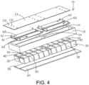
- the reinforcing member 62 may be connected to the plurality of first batteries 30 simultaneously, and as shown in FIG. 4 , the reinforcing member 62 may be a plate body, and the plate body is simultaneously connected to the plurality of first batteries 30, and the plurality of fixing members 61 may be provided on the reinforcing member 62.
- the top cover 13 may be provided with a plurality of configuration holes 131, and the fixing member 61 may respectively pass through the configuration holes 131.
- the reinforcing member 62 may be connected to one first battery 30, and one reinforcing member 62 corresponds to one fixing member 61.
- the connecting component 60 may be provided in plurality.
- the battery box 10 further includes a partition beam 14.
- the partition beam 14 is arranged in the frame 12, and the first battery 30 and the second battery 40 are located on both sides of the partition beam 14 respectively.
- One partition beam 14 may divide the accommodating space enclosed by the frame 12 into two sub-accommodating spaces, and the first battery 30 and the second battery 40 may be located in the two sub-accommodating spaces respectively. In this manner, when the battery is in detachment, the first battery 30 or the second battery 40 in one sub-accommodating space may be removed independently.
- the battery box 10 when the battery box 10 includes a partition beam 14, the battery box 10 is formed with two sub-accommodating spaces 141.
- the first battery 30 and the second battery 40 are respectively arranged in the two sub-accommodating spaces 141, and the first connector 20 and the second connector 50 are respectively disposed in the two sub-accommodating spaces 141.
- a plurality of first batteries 30 and a plurality of second batteries 40 are respectively disposed in the two sub-accommodating spaces 141.
- the first connector 20 may simultaneously detach the plurality of first batteries 30 from one sub-accommodating space 141
- the second connector 50 may simultaneously detach the plurality of second batteries 40 from another sub-accommodating space 141.
- Each sub-accommodating space 141 may correspond to at least one connecting component 60.
- the battery box 10 may include at least two partition beams 14.
- the two partition beams 14 may be arranged in an intersecting manner, so that four sub-accommodating spaces 141 may be formed.
- the battery box 10 may further include a plurality of third batteries and a plurality of fourth batteries, correspondingly, the third batteries and the fourth batteries may be arranged in the battery box 10 through the third connector and the fourth connector, respectively.
- the battery box 10 may include at least two partition beams 14.
- the two partition beams 14 may be arranged in an intersecting manner, so that four sub-accommodating spaces 141 may be formed.
- two adjacent sub-accommodating spaces 141 are both provided with the first battery 30 therein
- another two adjacent sub-accommodating spaces 141 are both provided with the second battery 40 therein.
- the first connector 20 may correspond to the first battery 30 in the two sub-accommodating spaces 141
- the second connector 50 may correspond to the second battery 40 in the two sub-accommodating spaces 141.
- the first connector 20 is located between the partition beam 14 and the bottom plate 11, so that the partition beam 14 and the bottom plate 11 can reliably clamp the first connector 20, thereby ensuring the stability of the first connector 20.
- the first connector 20 may be exposed, so that the first connector 20 may be detached from the frame 12, so as to facilitate maintenance of the first battery 30 in an independent manner.
- the partition beam 14 and the bottom plate 11 may be engaged with each other, the partition beam 14 and the bottom plate 11 may be connected by one or more fasteners, such as bolts, and the partition beam 14 and the bottom plate 11 may be riveted by one or more rotary tapping screws, the disclosure is not limited thereto as long as the connection strength is ensured and the disassembly is simple.
- the partition beam 14 and the first connector 20 may be engaged with each other, the partition beam 14 and the first connector 20 may be connected through one or more fasteners, such as bolts, and the partition beam 14 and the first connector 20 may be riveted through one or more rotary tapping screws.
- the partition beam 14 and the first connector 20 may only abut against each other, the disclosure is not limited thereto as long as the connection strength is ensured and the disassembly is simple.
- the first connector 20 and the second connector 50 may be located below the partition beam 14 and the frame 12 and above the bottom plate 11, so that the first connector 20 and the second connector 50 may be stably arranged in the battery box 10 to ensure the stability of the first battery 30 and the second battery 40.
- the connection between the bottom plate 11 and the frame 12 and the bottom plate 11 and the partition beam 14 may be released.
- the first connector 20 and the second connector 50 may be exposed, so that the connection between the first connector 20 and the frame 12 is released, and the connection between the first connector 20 and the partition beam 14 is released, and the first connector 20 and the first battery may be disassembled simultaneously.
- the connection between the second connector 50 and the frame 12 may be released, and the connection between the second connector 50 and the partition beam 14 may be released, so that the second connector 50 and the second battery 40 may be disassembled simultaneously.
- the bottom plate 11 is an integral structure, which is not only simple in structure, but also ensures the sealing performance.
- connection method and setting method of the second connector 50 may be derived from the connection method and setting method of the first connector 20, which will not be repeated here.
- the battery pack includes a first connector 20 and a second connector 50, the first battery 30 is arranged on the first connector 20, and the second battery 40 is arranged on the second connector 50.
- the battery box 10 includes the frame 12 and the top cover 13, the first connector 20 is connected to the bottom portion of the frame 12, the second connector 50 is connected to the bottom portion of the frame 12, and the top cover 13 is arranged on the top portion of the frame 12 to form a space for accommodating the battery.
- the bottom plate 11 is removed from the battery pack in this embodiment, that is, the first connector 20 and the second connector 50 realize the protection for the bottom portion of the battery box 10, and the independent detachment of the battery is also convenient.
- the battery box 10 further includes a partition beam 14, the partition beam 14 is arranged in the frame 12, and the first battery 30 and the second battery 40 are respectively located on both sides of the partition beam 14.
- the first connector 20 and the second connector 50 are connected to the bottom portion of the partition beam 14, and the first connector 20 and the second connector 50 realize the protection for the bottom portion of the battery box 10.
- FIG. 2 to FIG. 4 may be the same as those of the battery pack in FIG. 1 , which will not be repeated here. The difference is that, in the battery pack of FIG. 2 to FIG. 4 , the bottom plate 11 in FIG. 1 may be removed.
- the battery pack shown in FIG. 2 to FIG. 4 may also be provided with the bottom plate 11 shown in FIG. 1 , the disclosure is not limited thereto.
- the first battery 30 is a quadrangular prism battery
- the second battery 40 is a quadrangular prism battery, so that the internal space of the battery box 10 may be utilized to the maximum extent to meet the energy capacity.
- the first battery 30 is a quadrangular prism battery
- the second battery 40 is a quadrangular prism battery, that is, the first battery 30 and the second battery 40 may be square batteries.
- An embodiment of the present disclosure further provides a method for disassembling a battery pack.
- the disassembling method for a battery pack includes the following steps.
- the first battery 30 may be simultaneously detached from the battery box 10 along with the first connector 20 without affecting the second battery 40, so as to facilitate the maintenance of the battery pack, improve the maintenance efficiency of the battery pack, and save maintenance costs.
- the step of disconnecting the first connector 20 from the battery box 10 includes: disconnecting the first connector 20 and the frame 12, that is, the first connector 20 and the frame 12 are detachably connected in a normal state.
- the connection relationship between the first connector 20 and the frame 12 needs to be released, so that the first connector 20 may be detached from the frame 12, thereby realizing the independent detachment of the first battery 30.
- the bolts connecting the first connector 20 and the frame 12 are detached, thereby releasing the connection between the first connector 20 and the frame 12.
- the step of disconnecting the first connector 20 and the battery box 10 further includes: before disconnecting the first connector 20 from the frame 12, the connection between the bottom plate 11 and the frame 12 is disconnected, so that the first connector 20 may be exposed. Accordingly, the connection between the first connector 20 and the frame 12 may be released subsequently.
- the bolts connecting the bottom plate 11 and the frame 12 are removed, thereby disconnecting the first connector 20 from the frame 12.
- the step of disconnecting the first connector 20 from the battery box 10 further includes: disconnecting the top cover 13 and the first battery 30, so that the first connector 20 may carry the first battery 30 to detach from the battery box 10.
- the connecting component 60 connecting the top cover 13 and the first battery 30 is removed.
- the nut may be removed from the bolt, so that the connection between the connecting component 60 and the top cover 13 is released. In this manner, at least a part of the connecting component 60 may be detached from the battery box 10 along with the first battery 30.
- the first connector 20 is detached from the bottom portion of the frame 12, so that the first battery 30 is detached through the bottom portion of the frame 12, that is, when the first battery 30 is removed, the first battery 30 may be pulled out from the bottom of the frame 12. Under the circumstances, the top cover 13 may not be disassembled, thereby reducing disassembly steps.
- the bolts connecting the bottom plate 11 and the frame 12 are removed, the bottom plate 11 is removed, and then the bolts connecting the first connector 20 and the frame 12 are removed.
- the removal of the connecting component 60 connecting the top cover 13 and the first battery 30 may be prior to the above two steps, or may be performed after the above two steps, or may be performed before the above two steps, the disclosure is not limited thereto.
- the first connector 20 may be detached from the bottom portion of the frame 12.
- the method for disassembling a battery pack further includes: disconnecting the second connector 50 and the battery box 10, and detaching the second connector 50 from the battery box 10, wherein the second battery 40 is simultaneously detached from the battery box 10 along with the second connector 50.
- the first battery 30 and the second battery 40 may be independent detached through the first connector 20 and the second connector 50, so that the battery in the battery pack may be directly maintained in a targeted manner, thereby improving the maintenance efficiency.
- the disassembly process of the second connector 50 is not repeated here, and reference may be made to the disassembly process of the first connector 20 described above.
- the method for disassembling the battery pack is applicable to the above-mentioned battery pack.
Landscapes
- Chemical & Material Sciences (AREA)
- Chemical Kinetics & Catalysis (AREA)
- Electrochemistry (AREA)
- General Chemical & Material Sciences (AREA)
- Engineering & Computer Science (AREA)
- Manufacturing & Machinery (AREA)
- Aviation & Aerospace Engineering (AREA)
- Battery Mounting, Suspending (AREA)
Abstract
Description
- The present disclosure relates to the technical field of batteries, and in particular, to a battery pack and a method for disassembling the battery pack.
- In the related art, there are multiple batteries configured in the battery pack. After the battery pack is used for a long time, some batteries in the battery pack might not operate properly, so they need to be maintained. In the maintenance process, all batteries need to be taken out, which affects the maintenance efficiency of the battery pack.
- The present disclosure provides a battery pack and a method for disassembling the battery pack.
- According to a first aspect of the present disclosure, a battery pack is provided. The battery pack includes a battery box, a first connector, a first battery, and a second battery. The first connector is detachably disposed in the battery box. The first battery is fixed on the first connector to be arranged in the battery box through the first connector. The second battery is arranged in the battery box. The first connector is not fixedly connected to the second battery to prevent the second battery from blocking the first battery and the first connector from being simultaneously removed from the battery box.
- According to a second aspect of the present disclosure, a method for disassembling a battery pack is provided. The method includes following steps. Disconnecting a first connector from a battery box, and detaching the first connector from the battery box, wherein a first battery is detached simultaneously with the first connector, and a second battery is retained in the battery box.
- For a better understanding of the disclosure, reference may be made to exemplary embodiments shown in the following drawings. The components in the drawings are not necessarily to scale and related elements may be omitted, or in some instances proportions may have been exaggerated, so as to emphasize and clearly illustrate the features described herein. In addition, related elements or components can be variously arranged, as known in the art. Further, in the drawings, like reference numerals designate same or like parts throughout the several views.
-
FIG. 1 is an exploded schematic view of a battery pack according to a first exemplary embodiment. -
FIG. 2 is an exploded schematic view of a battery pack according to a second exemplary embodiment. -
FIG. 3 is an assembled schematic view of the battery pack according to the second exemplary embodiment. -
FIG. 4 is an exploded schematic view of a battery pack according to a third exemplary embodiment. -
FIG. 5 is a schematic view of a partial structure of a battery pack according to a fourth exemplary embodiment. -
FIG. 6 is a schematic flowchart of a method for disassembling a battery pack according to an exemplary embodiment. - The technical solutions in the exemplary embodiments of the disclosure will be described clearly and explicitly in conjunction with the drawings in the exemplary embodiments of the disclosure. The description proposed herein is just the exemplary embodiments for the purpose of illustrations only, not intended to limit the scope of the disclosure, so it should be understood that and various modifications and variations could be made thereto without departing from the scope of the disclosure.
- In the description of the present disclosure, unless otherwise specifically defined and limited, the terms "first", "second" and the like are only used for illustrative purposes and are not to be construed as expressing or implying a relative importance. The term "plurality" is two or more. The term "and/or" includes any and all combinations of one or more of the associated listed items.
- In particular, a reference to "the" object or "a" and "an" object is intended to denote also one of a possible plurality of such objects. Unless otherwise defined or described, the terms "connect", "fix" should be broadly interpreted, for example, the term "connect" can be "fixedly connect", "detachably connect", "integrally connect", "electrically connect" or "signal connect". The term "connect" also can be "directly connect" or "indirectly connect via a medium". For the persons skilled in the art, the specific meanings of the abovementioned terms in the present disclosure can be understood according to the specific situation.
- Further, in the description of the present disclosure, it should be understood that spatially relative terms, such as "above", "below" "inside", "outside" and the like, are described based on orientations illustrated in the figures, but are not intended to limit the exemplary embodiments of the present disclosure.
- In the context, it should also be understood that when an element or features is provided "outside" or "inside" of another element(s), it can be directly provided "outside" or "inside" of the other element, or be indirectly provided "outside" or "inside" of the another element(s) by an intermediate element.
- An embodiment of the present disclosure provides a battery pack, please refer to
FIG. 1 to FIG. 4 , the battery pack includes abattery box 10, afirst connector 20, afirst battery 30, and asecond battery 40. Thefirst connector 20 is detachably arranged in thebattery box 10. Thefirst battery 30 is fixed on thefirst connector 20, so as to be arranged in thebattery box 10 through thefirst connector 20. Thesecond battery 40 is arranged in thebattery box 10, and thefirst connector 20 is not fixedly connected to thesecond battery 40 to prevent thesecond battery 40 from blocking thefirst battery 30 and thefirst connector 20 from being simultaneously detached from thebattery box 10. - The battery pack in an embodiment of the present disclosure includes the
battery box 10, thefirst connector 20, thefirst battery 30, and thesecond battery 40. Both thefirst battery 30 and thesecond battery 40 are provided on thebattery box 10. By the configuration that thefirst battery 30 is fixed on thefirst connector 20, thefirst connector 20 is detachably arranged on thebattery box 10, and thesecond battery 40 is not fixedly connected to thefirst connector 20, thefirst battery 30 and thefirst connector 20 may be simultaneously detached from thebattery box 10 without affecting thesecond battery 40, so as to facilitate the maintenance of the battery pack, thereby improving the performance of the battery pack. - It should be noted that, the
first battery 30 is fixed on thefirst connector 20, and thefirst connector 20 is detachably arranged in thebattery box 10, so as to ensure that thefirst battery 30 is stably arranged in thebattery box 10. It is possible to prevent thefirst battery 30 from shaking during normal use. When thefirst battery 30 is subjected to a maintenance process, the connection between thefirst connector 20 and thebattery box 10 may be released, so that thefirst connector 20 may be detached from thebattery box 10, and that thefirst battery 30 may be taken out from thebattery box 10, and subsequent maintenance may be performed. For example, thefirst battery 30 on thefirst connector 20 is detached\ and is replaced with a newfirst battery 30 to be arranged on the originalfirst connector 20. Subsequently, thefirst battery 30 and thefirst connector 20 are arranged on thebattery box 10. Alternatively, thefirst battery 30 and thefirst connector 20 are directly replaced with newfirst battery 30 and newfirst connector 20, which are then arranged on thebattery box 10. - Neither the
first battery 30 nor thefirst connector 20 may be fixedly connected to thesecond battery 40, so that when thefirst battery 30 and thefirst connector 20 are detached from thebattery box 10, thesecond battery 40 will not obstruct thefirst battery 30 and thefirst connector 20. In this manner, it is possible to ensure independent detachment of thefirst battery 30 and thefirst connector 20, without affecting thesecond battery 40. - A battery includes a cell and an electrolyte, and is the smallest unit capable of performing electrochemical reactions such as charge/discharge. The cell refers to a unit formed by winding or laminating a stack portion, and the stack portion includes a first electrode, a separator and a second electrode. When the first electrode is a positive electrode, the second electrode is a negative electrode. The polarities of the first electrode and the second electrode may be interchanged.
- It should be noted that neither the
first battery 30 nor thefirst connector 20 is fixedly connected to thesecond battery 40, and thesecond battery 40 may be stably arranged in thebattery box 10. Under the circumstances, thesecond battery 40 may be directly fixed on thebattery box 10. Alternatively, thesecond battery 40 may be fixed on thebattery box 10 through other components, the disclosure provides no limitation thereto. - In an embodiment, the
first battery 30 is adhesively connected to thefirst connector 20, so as to ensure that thefirst battery 30 is stably connected to thefirst connector 20, and to avoid problem such as shaking of thefirst battery 30, thereby improving the safety performance of thefirst battery 30. Thefirst battery 30 and thefirst connector 20 may be bonded by a thermally conductive structural adhesive, which not only may ensure the strength of the connection, but also may realize heat transfer by the thermally conductive structural adhesive, thereby improving the heat dissipation capability of thefirst battery 30. - In some embodiments, it is not excluded that the
first battery 30 and thefirst connector 20 may be connected through engagement connection, for example. - In an embodiment, there are a plurality of
first batteries 30, and the plurality offirst batteries 30 are all fixed on thefirst connector 20, so that when thefirst connector 20 is detached from thebattery box 10, the multiplefirst batteries 30 may be simultaneously detached from thebattery box 10 along with thefirst connector 20. - The plurality of
first batteries 30 may form abattery module 1 and then be fixed on thefirst connector 20, and specifically, the plurality offirst batteries 30 may be fixed through end plates and lateral plates to form thebattery module 1, and finally arranged in thebattery box 10, as shown inFIG 5 . The plurality offirst batteries 30 may be independently fixed on thefirst connector 20, that is, there is no need to group the plurality offirst batteries 30. Under the circumstances, the end plate and the lateral plate may be removed. - In an embodiment, as shown in
FIG. 1 ,FIG. 2 andFIG. 4 , the battery pack further includes asecond connector 50, and thesecond connector 50 is detachably arranged in thebattery box 10. Thesecond battery 40 is fixed on thesecond connector 50 to be arranged in thebattery box 10 through thesecond connector 50. Thefirst battery 30 is not fixedly connected to thesecond connector 50, so as to prevent thefirst battery 30 from blocking thesecond battery 40 and thesecond connector 50 from being simultaneously detached from thebattery box 10. In this manner, when thesecond battery 40 and thesecond connector 50 are simultaneously detached from thebattery box 10, the detachment will not affect thefirst battery 30, so as to facilitate the maintenance of the battery pack. - The
first battery 30 may be detachably arranged on thebattery box 10 through thefirst connector 20, and thesecond battery 40 may be detachably arranged on thebattery box 10 through thesecond connector 50. In this manner, thefirst battery 30 or thesecond battery 40 may be independently detached from thebattery box 10 according to maintenance requirements, thereby improving maintenance efficiency. - In an embodiment, the
second battery 40 is adhesively connected to thesecond connector 50, such that that thesecond battery 40 is ensured to be stably connected to thesecond connector 50, and problem such as shaking of thesecond battery 40 is avoided, thereby improving the safety performance of thesecond battery 40. Thesecond battery 40 and thesecond connector 50 may be bonded through the thermally conductive structural adhesive, which not only may ensure the strength of the connection, but also may realize heat transfer through the thermally conductive structural adhesive, thereby improving the heat dissipation capability of thesecond battery 40. - In some embodiments, it is not excluded that the
second battery 40 and thesecond connector 50 may be connected through engagement connection, for example. - In an embodiment, there are a plurality of
second batteries 40, and the plurality ofsecond batteries 40 are all fixed on thesecond connector 50, so that when thesecond connector 50 is detached from thebattery box 10, the plurality ofsecond batteries 40 may be simultaneously detached from thebattery box 10 along with thesecond connector 50. - The plurality of
second batteries 40 may from a battery module and then be fixed on thesecond connector 50, and specifically, the plurality ofsecond batteries 40 may be fixed through end plates and lateral plates to form the battery module. The plurality ofsecond batteries 40 may be independently fixed on thesecond connector 50, that is, there is no need to group the plurality ofsecond batteries 40. Under the circumstances, the end plate and the lateral plate may be removed. - It should be noted that the
first battery 30 and thesecond battery 40 may be the same type of batteries. In some embodiments, it is not excluded that thefirst battery 30 and thesecond battery 40 may be different types of batteries, the disclosure is not limited thereto. The plurality offirst batteries 30 may be connected in series or in parallel, and the plurality ofsecond batteries 40 may be connected in series or in parallel. For example, the plurality offirst batteries 30 form a first module, and the plurality ofsecond batteries 40 form a second module, and the first module and the second module may also be electrically connected. When thefirst battery 30 or thesecond battery 40 is in independent detachment, the connection relationship between the first module and the second module may be disconnected, so as to ensure that thefirst battery 30 and thesecond battery 40 do not affect each other. - Even if there is a connection relationship between the
first battery 30 and thesecond battery 40, for example, thefirst battery 30 and thesecond battery 40 are connected through the bus bar, because there is no connection relationship between thesecond battery 40 and thefirst connector 20, and there is no connection relationship between thesecond battery 40 and thesecond connector 50, when thefirst battery 30 and thesecond battery 40 are independently detached, it is only necessary to disconnect the connection relationship between thefirst battery 30 and thesecond battery 40, thefirst battery 30 can be detached along with thefirst connector 20, or thesecond battery 40 is detached along with thesecond connector 50. In this manner, the overall structure of the battery pack may not be damaged. - In some embodiments, the
first connector 20 and thesecond connector 50 may be connected, but thefirst connector 20 and thesecond connector 50 are detachably connected, thefirst connector 20 and thesecond connector 50 may be directly connected, or thefirst connector 20 and thesecond connector 50 may be indirectly connected. - In some embodiments, the
first connector 20 and thesecond connector 50 are arranged at intervals, so that when thefirst connector 20 and thesecond connector 50 are in independent detachment, it is possible to omit the detachment of the direct connection relationship between thefirst connector 20 and thesecond connector 50. In this way, the connection strength between thefirst connector 20 or thesecond connector 50 and thebattery box 10 may not be affected. - In an embodiment, the
first connector 20 includes a circulating flow channel, and the circulating flow channel may be provided with a heat exchange medium, such as a liquid heat exchange medium, a gas exchange medium or a phase change material, etc., so that the heat transfer performance of thefirst connector 20 may be improved, so as to realize cooling or preheating of thefirst battery 30. - In an embodiment, the
second connector 50 includes a circulating flow channel, and the circulating flow channel may be provided with a heat exchange medium, such as a liquid heat exchange medium, a gas exchange medium or a phase change material, etc., so that the heat transfer performance of thesecond connector 50 may be improved, so as to realize cooling or preheating of thesecond battery 40. - It should be noted that the
first connector 20 and thesecond connector 50 form a temperature adjustment mechanism of the battery pack, so as to realize the temperature adjustment of the batteries inside the battery pack, thereby ensuring the use performance of the battery pack. Thefirst connector 20 may be a plate-like structure, thesecond connector 50 may be a plate-like structure, and the plate-like structure may include upper and lower plates stacked together, so as to form a circulating flow channel between the two plates. The specific structural form of the plate-like structure and the specific structural form of the circulating flow channel are not limited in the disclosure, and may be selected according to actual needs. - In an embodiment, as shown in
FIG. 1 , thebattery box 10 includes abottom plate 11 and aframe 12. Theframe 12 is arranged around thebottom plate 11. Thefirst connector 20 is arranged in theframe 12, and at least one of thebottom plate 11 and theframe 12 is connected to thefirst connector 20, so as to ensure that thefirst connector 20 is stably arranged in thebattery box 10. At least one of thebottom plate 11 and theframe 12 is detachably connected to thefirst connector 20, that is, thebottom plate 11 is detachably connected to thefirst connector 20, and/or theframe 12 is detachably connected to thefirst connector 20. In this manner, it is also possible to ensure that thefirst connector 20 may be detached from thebattery box 10. - In an embodiment, the
second battery 40 is disposed on thebattery box 10 through thesecond connector 50, and at least one of thebottom plate 11 and theframe 12 is detachably connected to thesecond connector 50. - It should be noted that the arrangement of the
frame 12 around thebottom plate 11 does not mean a specific configuration, and the key point is to explain that theframe 12 forms a circumferentially closed space. Theframe 12 is connected to thebottom plate 11, and theframe 12 may be disposed on thebottom plate 11, or theframe 12 may be connected to the circumferential edge of thebottom plate 11, the disclosure is not limited thereto. - The
bottom plate 11 and theframe 12 form an accommodating space, thefirst connector 20 is arranged in the accommodating space, thesecond connector 50 is arranged in the accommodating space, that is, thefirst battery 30 and thesecond battery 40 are arranged in the accommodating space. Thefirst connector 20 and thesecond connector 50 may be detached from thebottom plate 11 and theframe 12 independently. For example, thefirst connector 20 and thesecond connector 50 may be taken out from the top portion of theframe 12, or thefirst connector 20 and thesecond connector 50 may be taken out from the bottom portion of theframe 12. - In an embodiment, the
frame 12 is detachably connected to thebottom plate 11, and theframe 12 is detachably connected to thefirst connector 20. That is, during the detachment process of thefirst connector 20, if thefirst connector 20 is taken out from the bottom portion of theframe 12, it is necessary to first detach thebottom plate 11 from theframe 12, and then complete the detachment of thefirst connector 20, so as to realize the separate removal of thefirst battery 30. - The
frame 12 and thebottom plate 11 may be engaged with each other, theframe 12 and thebottom plate 11 may be connected through one or more fasteners, such as bolts, and theframe 12 and thebottom plate 11 may be riveted through one or more rotary tapping screws, the disclosure is not limited thereto as long as the connection strength is ensured and the detachment is simple. - The
frame 12 and thefirst connector 20 may be connected through engagement connection, and theframe 12 and thefirst connector 20 may be connected through one or more fasteners, such as bolts, and theframe 12 and thefirst connector 20 may be riveted through one or more rotary tapping screws, the disclosure is not limited thereto as long as the connection strength is ensured and the disassembly is simple. - In an embodiment, as shown in
FIG. 1 , thefirst connector 20 is located between theframe 12 and thebottom plate 11, so that theframe 12 and thebottom plate 11 may reliably clamp thefirst connector 20 to ensure the stability of thefirst connector 20. After thebottom plate 11 is separated from theframe 12, thefirst connector 20 may be exposed, so that thefirst connector 20 may be removed from the bottom portion of theframe 12, so as to facilitate maintenance of thefirst battery 30 in an independent manner. - In an embodiment, as shown in
FIG. 1 , thebattery box 10 further includes atop cover 13. Thetop cover 13 is disposed on theframe 12, and thetop cover 13 is detachably connected to thefirst battery 30. In this manner, in normal use of the battery pack, thetop cover 13 may realize fixing of thefirst battery 30, and when thefirst battery 30 needs to be detached, thetop cover 13 may release thefirst battery 30. - The
top cover 13 and thebottom plate 11 are connected to the top portion and the bottom portion of theframe 12, respectively, so that thebattery box 10 has a closed accommodating space, so that the battery inside thebattery box 10 may be protected. - It should be noted that the
top cover 13 may be connected to thesecond battery 40, and when thefirst battery 30 is detached, thetop cover 13 may be disconnected from thefirst battery 30. If thefirst battery 30 is removed from the bottom portion of theframe 12, the connection between thetop cover 13 and thesecond battery 40 may not be released. If thefirst battery 30 is removed from the top portion of theframe 12, the connection between thetop cover 13 and thesecond battery 40 may be released, and thetop cover 13 may be removed. In some embodiments, it is not excluded that thetop cover 13 may be provided in plurality, and one top cover may correspond to thefirst battery 30 while another top cover may correspond to thesecond battery 40. - In some embodiments, the
top cover 13 and thefirst battery 30 may be directly connected, for example, thetop cover 13 and thefirst battery 30 may be connected through engagement connection. - In an embodiment, as shown in
FIG. 1 , the battery pack further includes a connectingcomponent 60, and thetop cover 13 and thefirst battery 30 are connected through the connectingcomponent 60, which not only ensures the stability of the connection between thetop cover 13 and thefirst battery 30, but also makes it easy to release the connection between thetop cover 13 and thefirst battery 30. - The connecting
component 60 may include screws, bolts, keys and other structures. For example, the connectingcomponent 60 includes bolts, and thefirst battery 30 may be provided with threaded holes, so that the bolts may be fit into the threaded holes after passing through thetop cover 13. Thefirst battery 30 may have threaded holes on its casing structure, or, thefirst battery 30 may be provided with a protruding structure at outside, and the protruding structure may be provided with threaded holes. - In an embodiment, the
top cover 13 is detachably connected to at least a part of the connectingcomponent 60, and thefirst battery 30 is fixedly connected to at least a part of the connectingcomponent 60, so that when thefirst battery 30 is disassembled, the connectingcomponent 60 releases the connection with thetop cover 13 and at least a portion of the connectingcomponent 60 may be removed along with thefirst battery 30. - In some embodiments, the connecting
component 60 may include a first engaging portion and a second engaging portion. The first engaging portion is fixed on thetop cover 13, the second engaging portion is fixed on thefirst battery 30, and the first engaging portion is engaged with the second engaging portion. When thefirst battery 30 is in detachment, the engagement connection between the first engaging portion and the second engaging portion may be released, so that the first engaging portion remains on thetop cover 13, and the second engaging portion is removed along with thefirst battery 30. - In an embodiment, the bonding of the connecting
component 60 and thefirst battery 30 not only may ensure the stability of the connection between the connectingcomponent 60 and thefirst battery 30, but also enable at least a part of the connectingcomponent 60 to be detached along with thefirst battery 30. The connectingcomponent 60 and thefirst battery 30 may be bonded through structural adhesive, and further, the connectingcomponent 60 and thefirst battery 30 may be bonded through thermally conductive structural adhesive, which not only may ensure the strength of connection, but also the thermally conductive structural adhesive may realize thermal transfer, so as to improve the heat dissipation capability of thefirst battery 30. - In some embodiments, it is not excluded that the connecting
component 60 and thefirst battery 30 are detachably connected. For example, an adhesive layer with relatively weak bonding strength is used between the connectingcomponent 60 and thefirst battery 30. In this manner, after the connectingcomponent 60 is simultaneously detached along with thefirst battery 30, the connectingcomponent 60 may be detached from thefirst battery 30, so as to repair or replace thefirst battery 30. - In an embodiment, as shown in
FIG. 1 andFIG. 4 , the connectingcomponent 60 includes a fixingmember 61 andreinforcement member 62. The fixingmember 61 is detachably connected to thetop cover 13. The reinforcingmember 62 is connected to one end of the fixingmember 61 facing thefirst battery 30. The reinforcingmember 62 is adhesively connected to thefirst battery 30, which not only may ensure the connection strength between the reinforcingmember 62 and thefirst battery 30, but also may realize reliable protection for thefirst battery 30 and increase the stability of thefirst battery 30. Therefore, when thefirst battery 30 is detached, the connection between the fixingmember 61 and thetop cover 13 may be released. - The fixing
member 61 may be a bolt, and the connectingcomponent 60 may further include a nut. The bolt passes through thetop cover 13 and is then fixed by the nut. When thefirst battery 30 is detached, the nut may be removed from the bolt, so that the connection between thefirst battery 30 and thetop cover 13 is released. The fixingmember 61 may also be a protruding structure, and the protruding structure is inserted into thetop cover 13 to realize the connection between the two. When disassembling thefirst battery 30, thefirst battery 30 may drive the protruding structure to detach from thetop cover 13. - In some embodiments, the reinforcing
member 62 may be connected to the plurality offirst batteries 30 simultaneously, and as shown inFIG. 4 , the reinforcingmember 62 may be a plate body, and the plate body is simultaneously connected to the plurality offirst batteries 30, and the plurality of fixingmembers 61 may be provided on the reinforcingmember 62. Thetop cover 13 may be provided with a plurality of configuration holes 131, and the fixingmember 61 may respectively pass through the configuration holes 131. - In some embodiments, the reinforcing
member 62 may be connected to onefirst battery 30, and one reinforcingmember 62 corresponds to one fixingmember 61. - In an embodiment, the connecting
component 60 may be provided in plurality. - In an embodiment, as shown in
FIG. 1 to FIG. 4 , thebattery box 10 further includes apartition beam 14. Thepartition beam 14 is arranged in theframe 12, and thefirst battery 30 and thesecond battery 40 are located on both sides of thepartition beam 14 respectively. Onepartition beam 14 may divide the accommodating space enclosed by theframe 12 into two sub-accommodating spaces, and thefirst battery 30 and thesecond battery 40 may be located in the two sub-accommodating spaces respectively. In this manner, when the battery is in detachment, thefirst battery 30 or thesecond battery 40 in one sub-accommodating space may be removed independently. - In some embodiments, when the
battery box 10 includes apartition beam 14, thebattery box 10 is formed with twosub-accommodating spaces 141. Thefirst battery 30 and thesecond battery 40 are respectively arranged in the twosub-accommodating spaces 141, and thefirst connector 20 and thesecond connector 50 are respectively disposed in the twosub-accommodating spaces 141. Correspondingly, a plurality offirst batteries 30 and a plurality ofsecond batteries 40 are respectively disposed in the twosub-accommodating spaces 141. Thefirst connector 20 may simultaneously detach the plurality offirst batteries 30 from onesub-accommodating space 141, and thesecond connector 50 may simultaneously detach the plurality ofsecond batteries 40 from anothersub-accommodating space 141. Eachsub-accommodating space 141 may correspond to at least one connectingcomponent 60. - In some embodiments, the
battery box 10 may include at least two partition beams 14. For example, the twopartition beams 14 may be arranged in an intersecting manner, so that foursub-accommodating spaces 141 may be formed. Under the circumstances, thebattery box 10 may further include a plurality of third batteries and a plurality of fourth batteries, correspondingly, the third batteries and the fourth batteries may be arranged in thebattery box 10 through the third connector and the fourth connector, respectively. - Referring to
FIG. 2 to FIG. 4 in combination, thebattery box 10 may include at least two partition beams 14. For example, the twopartition beams 14 may be arranged in an intersecting manner, so that foursub-accommodating spaces 141 may be formed. Under the circumstances, two adjacentsub-accommodating spaces 141 are both provided with thefirst battery 30 therein, and another two adjacentsub-accommodating spaces 141 are both provided with thesecond battery 40 therein. Thefirst connector 20 may correspond to thefirst battery 30 in the twosub-accommodating spaces 141, and thesecond connector 50 may correspond to thesecond battery 40 in the twosub-accommodating spaces 141. - In an embodiment, the
first connector 20 is located between thepartition beam 14 and thebottom plate 11, so that thepartition beam 14 and thebottom plate 11 can reliably clamp thefirst connector 20, thereby ensuring the stability of thefirst connector 20. After thebottom plate 11 is detached from theframe 12, thefirst connector 20 may be exposed, so that thefirst connector 20 may be detached from theframe 12, so as to facilitate maintenance of thefirst battery 30 in an independent manner. - The
partition beam 14 and thebottom plate 11 may be engaged with each other, thepartition beam 14 and thebottom plate 11 may be connected by one or more fasteners, such as bolts, and thepartition beam 14 and thebottom plate 11 may be riveted by one or more rotary tapping screws, the disclosure is not limited thereto as long as the connection strength is ensured and the disassembly is simple. - The
partition beam 14 and thefirst connector 20 may be engaged with each other, thepartition beam 14 and thefirst connector 20 may be connected through one or more fasteners, such as bolts, and thepartition beam 14 and thefirst connector 20 may be riveted through one or more rotary tapping screws. Thepartition beam 14 and thefirst connector 20 may only abut against each other, the disclosure is not limited thereto as long as the connection strength is ensured and the disassembly is simple. - In an embodiment, as shown in
FIG. 1 , thefirst connector 20 and thesecond connector 50 may be located below thepartition beam 14 and theframe 12 and above thebottom plate 11, so that thefirst connector 20 and thesecond connector 50 may be stably arranged in thebattery box 10 to ensure the stability of thefirst battery 30 and thesecond battery 40. When thefirst battery 30 or thesecond battery 40 is in independent detachment, the connection between thebottom plate 11 and theframe 12 and thebottom plate 11 and thepartition beam 14 may be released. Under the circumstances, thefirst connector 20 and thesecond connector 50 may be exposed, so that the connection between thefirst connector 20 and theframe 12 is released, and the connection between thefirst connector 20 and thepartition beam 14 is released, and thefirst connector 20 and the first battery may be disassembled simultaneously. Or, the connection between thesecond connector 50 and theframe 12 may be released, and the connection between thesecond connector 50 and thepartition beam 14 may be released, so that thesecond connector 50 and thesecond battery 40 may be disassembled simultaneously. - In some embodiments, it is not excluded that there may be at least two
bottom plates 11, and theindependent bottom plates 11 may correspond to thefirst connector 20 and thesecond connector 50 respectively. As shown inFIG. 1 , thebottom plate 11 is an integral structure, which is not only simple in structure, but also ensures the sealing performance. - It should be noted that the
second battery 40 is disposed on thebattery box 10 through thesecond connector 50, and the connection method and setting method of thesecond connector 50 may be derived from the connection method and setting method of thefirst connector 20, which will not be repeated here. - In an embodiment, as shown in
FIG. 2 to FIG. 4 , the battery pack includes afirst connector 20 and asecond connector 50, thefirst battery 30 is arranged on thefirst connector 20, and thesecond battery 40 is arranged on thesecond connector 50. Thebattery box 10 includes theframe 12 and thetop cover 13, thefirst connector 20 is connected to the bottom portion of theframe 12, thesecond connector 50 is connected to the bottom portion of theframe 12, and thetop cover 13 is arranged on the top portion of theframe 12 to form a space for accommodating the battery. - Compared with the battery pack in the above embodiment, the
bottom plate 11 is removed from the battery pack in this embodiment, that is, thefirst connector 20 and thesecond connector 50 realize the protection for the bottom portion of thebattery box 10, and the independent detachment of the battery is also convenient. - In an embodiment, as shown in
FIG. 2 to FIG. 4 , thebattery box 10 further includes apartition beam 14, thepartition beam 14 is arranged in theframe 12, and thefirst battery 30 and thesecond battery 40 are respectively located on both sides of thepartition beam 14. Thefirst connector 20 and thesecond connector 50 are connected to the bottom portion of thepartition beam 14, and thefirst connector 20 and thesecond connector 50 realize the protection for the bottom portion of thebattery box 10. - It should be noted that other structures of the battery pack in
FIG. 2 to FIG. 4 may be the same as those of the battery pack inFIG. 1 , which will not be repeated here. The difference is that, in the battery pack ofFIG. 2 to FIG. 4 , thebottom plate 11 inFIG. 1 may be removed. Of course, the battery pack shown inFIG. 2 to FIG. 4 may also be provided with thebottom plate 11 shown inFIG. 1 , the disclosure is not limited thereto. - In an embodiment, the
first battery 30 is a quadrangular prism battery, and thesecond battery 40 is a quadrangular prism battery, so that the internal space of thebattery box 10 may be utilized to the maximum extent to meet the energy capacity. Thefirst battery 30 is a quadrangular prism battery, and thesecond battery 40 is a quadrangular prism battery, that is, thefirst battery 30 and thesecond battery 40 may be square batteries. - An embodiment of the present disclosure further provides a method for disassembling a battery pack. Please refer to
FIG. 6 , the disassembling method for a battery pack includes the following steps. - Step S101, disconnecting the
first connector 20 from thebattery box 10; - Step S103, detaching the
first connector 20 from thebattery box 10, wherein thefirst battery 30 is detached simultaneously with thefirst connector 20, and thesecond battery 40 is retained in thebattery box 10. - In the method for disassembling the battery pack in an embodiment of the present disclosure, by disconnecting the
first connector 20 from thebattery box 10, thefirst battery 30 may be simultaneously detached from thebattery box 10 along with thefirst connector 20 without affecting thesecond battery 40, so as to facilitate the maintenance of the battery pack, improve the maintenance efficiency of the battery pack, and save maintenance costs. - In an embodiment, the step of disconnecting the
first connector 20 from thebattery box 10 includes: disconnecting thefirst connector 20 and theframe 12, that is, thefirst connector 20 and theframe 12 are detachably connected in a normal state. During maintenance of thefirst battery 30, the connection relationship between thefirst connector 20 and theframe 12 needs to be released, so that thefirst connector 20 may be detached from theframe 12, thereby realizing the independent detachment of thefirst battery 30. - In some embodiments, the bolts connecting the
first connector 20 and theframe 12 are detached, thereby releasing the connection between thefirst connector 20 and theframe 12. - In an embodiment, the step of disconnecting the
first connector 20 and thebattery box 10 further includes: before disconnecting thefirst connector 20 from theframe 12, the connection between thebottom plate 11 and theframe 12 is disconnected, so that thefirst connector 20 may be exposed. Accordingly, the connection between thefirst connector 20 and theframe 12 may be released subsequently. - In some embodiments, the bolts connecting the
bottom plate 11 and theframe 12 are removed, thereby disconnecting thefirst connector 20 from theframe 12. - In an embodiment, the step of disconnecting the
first connector 20 from thebattery box 10 further includes: disconnecting thetop cover 13 and thefirst battery 30, so that thefirst connector 20 may carry thefirst battery 30 to detach from thebattery box 10. - In some embodiments, the connecting
component 60 connecting thetop cover 13 and thefirst battery 30 is removed. Specifically, the nut may be removed from the bolt, so that the connection between the connectingcomponent 60 and thetop cover 13 is released. In this manner, at least a part of the connectingcomponent 60 may be detached from thebattery box 10 along with thefirst battery 30. - In an embodiment, the
first connector 20 is detached from the bottom portion of theframe 12, so that thefirst battery 30 is detached through the bottom portion of theframe 12, that is, when thefirst battery 30 is removed, thefirst battery 30 may be pulled out from the bottom of theframe 12. Under the circumstances, thetop cover 13 may not be disassembled, thereby reducing disassembly steps. - In some embodiments, the bolts connecting the
bottom plate 11 and theframe 12 are removed, thebottom plate 11 is removed, and then the bolts connecting thefirst connector 20 and theframe 12 are removed. The removal of the connectingcomponent 60 connecting thetop cover 13 and thefirst battery 30 may be prior to the above two steps, or may be performed after the above two steps, or may be performed before the above two steps, the disclosure is not limited thereto. After the bolts of thefirst connector 20 and theframe 12 are removed, thefirst connector 20 may be detached from the bottom portion of theframe 12. - In an embodiment, the method for disassembling a battery pack further includes: disconnecting the
second connector 50 and thebattery box 10, and detaching thesecond connector 50 from thebattery box 10, wherein thesecond battery 40 is simultaneously detached from thebattery box 10 along with thesecond connector 50. Thefirst battery 30 and thesecond battery 40 may be independent detached through thefirst connector 20 and thesecond connector 50, so that the battery in the battery pack may be directly maintained in a targeted manner, thereby improving the maintenance efficiency. The disassembly process of thesecond connector 50 is not repeated here, and reference may be made to the disassembly process of thefirst connector 20 described above. - In an embodiment, the method for disassembling the battery pack is applicable to the above-mentioned battery pack.
- Other embodiments of the disclosure will be apparent to those skilled in the art from consideration of the specification and practice of the disclosure disclosed herein. The disclosure is intended to cover any variations, uses or adaptations of the disclosure. These variations, uses, or adaptations follow the general principles of the disclosure and include common general knowledge or conventional technical means in the art that are not disclosed in the present disclosure. The specification and embodiments are illustrative.
Claims (25)
- A battery pack, comprising:a battery box (10);a first connector (20), which is detachably disposed in the battery box (10);a first battery (30), which is fixed on the first connector (20) to be arranged in the battery box (10) through the first connector (20);a second battery (40), which is arranged in the battery box (10), wherein the first connector (20) is not fixedly connected to the second battery (40) to prevent the second battery (40) from blocking the first battery (30) and the first connector (20) from being simultaneously removed from the battery box (10).
- The battery pack according to claim 1, wherein the first battery (30) is adhesively connected to the first connector (20).
- The battery pack according to claim 1, wherein the first battery (30) is provided in plurality, and the plurality of first batteries (30) are all fixed on the first connector (20).
- The battery pack according to claim 1, further comprising a second connector (50), wherein the second connector (50) is detachably arranged in the battery box (10), the second battery (40) is fixed on the second connector (50) to be arranged in the battery box (10) through the second connector (50);
wherein the first battery (30) is not fixedly connected to the second connector (50), so as to prevent the first battery (30) from blocking the second battery (40) and the second connector (50) from being simultaneously removed from the battery box (10). - The battery pack according to claim 4, wherein the second battery (40) is adhesively connected to the second connector (50).
- The battery pack according to claim 4, wherein the second battery (40) is provided in plurality, and the plurality of second batteries (40) are all fixed on the second connector (50).
- The battery pack according to claim 4, wherein the first connector (20) and the second connector (50) are arranged at intervals.
- The battery pack according to any one of claims 1-7, wherein the battery box (10) comprises:a bottom plate (11);a frame (12), which is arranged around the bottom plate (11);wherein the first connector (20) is arranged in the frame (12), and the bottom plate (11) is detachably connected to the first connector (20), and/or the frame (12) is detachably connected to the first connector (20).
- The battery pack according to claim 8, wherein the frame (12) is detachably connected to the bottom plate (11), and the frame (12) is detachably connected to the first connector (20).
- The battery pack according to claim 8, wherein the first connector (20) is located between the frame (12) and the bottom plate (11), such that after the bottom plate (11) is separated from the frame (12), the first connector (20) is detachable from the frame (12).
- The battery pack according to claim 8, wherein the battery box (10) further comprises a top cover (13), the top cover (13) is arranged on the frame (12), and the top cover (13) is detachably connected to the first battery (30).
- The battery pack according to claim 11, further comprising a connecting component (60), and the top cover (13) is connected to the first battery (30) through the connecting component (60).
- The battery pack according to claim 12, wherein the top cover (13) is detachably connected to at least a part of the connecting component (60), and the first battery (30) is fixedly connected to at least a part of the connecting component (60).
- The battery pack according to claim 13, wherein the connecting component (60) is adhesively connected to the first battery (30).
- The battery pack according to claim 14, wherein the connecting component (60) comprises:a fixing member (61), which is detachably connected to the top cover (13);a reinforcing member (62), which is connected to one end of the fixing member (61) facing the first battery (30), wherein the reinforcing member (62) is adhesively connected to the first battery (30).
- The battery pack according to claim 8, wherein the battery box (10) further comprises a partition beam (14), the partition beam (14) is arranged in the frame (12), and the first battery (30) and the second battery (40) are located on both sides of the partition beam (14) respectively.
- The battery pack according to claim 16, wherein the first connector (20) is located between the partition beam (14) and the bottom plate (11), such that after the bottom plate (11) is separated from the frame (12), the first connector (20) is detachable from the frame (12).
- The battery pack according to claim 1, further comprising a second connector (50), the second battery (40) is disposed on the second connector (50), the battery box (10) comprises a frame (12) and a top cover (13), the first connector (20) is connected to a bottom portion of the frame (12), the second connector (50) is connected to the bottom portion of the frame (12), and the top cover (13) is arranged on the frame (12).
- The battery pack according to claim 18, wherein the battery box (10) further comprises a partition beam (14), the partition beam (14) is arranged in the frame (12), the first battery (30) and the second battery (40) are arranged respectively on both sides of the partition beam (14);
wherein the first connector (20) and the second connector (50) are connected to a bottom portion of the partition beam (14). - A method for disassembling a battery pack, the method comprising:disconnecting a first connector (20) from a battery box (10);detaching the first connector (20) from the battery box (10), wherein a first battery (30) is detached simultaneously with the first connector (20), and a second battery (40) is retained in the battery box (10).
- The method for disassembling the battery pack according to claim 20, wherein the step of disconnecting the first connector (20) from the battery box (10) comprises:
disconnecting the first connector (20) from a frame (12). - The method for disassembling the battery pack according to claim 21, wherein the step of disconnecting the first connector (20) from the battery box (10) further comprises: disconnecting a bottom plate (11) from the frame (12) before the first connector (20) is disconnected from the frame (12).
- The method for disassembling the battery pack according to claim 21 or 22, wherein the step of disconnecting the first connector (20) from the battery box (10) further comprises:
disconnecting a top cover (.13) from the first battery (30). - The method for disassembling the battery pack according to claim 23, wherein the first connector (20) is detached from a bottom portion of the frame (12), such that the first battery (30) is removed via the bottom portion of the frame (12).
- The method for disassembling the battery pack according to claim 20, further comprising:disconnecting a second connector (50) from the battery box (10);detaching the second connector (50) from the battery box (10), wherein the second battery (40) is simultaneously detached with the second connector (50).
Applications Claiming Priority (1)
| Application Number | Priority Date | Filing Date | Title |
|---|---|---|---|
| CN202210376228.5A CN114744272A (en) | 2022-04-11 | 2022-04-11 | Battery pack and method for disassembling battery pack |
Publications (2)
| Publication Number | Publication Date |
|---|---|
| EP4261979A2 true EP4261979A2 (en) | 2023-10-18 |
| EP4261979A3 EP4261979A3 (en) | 2024-05-29 |
Family
ID=82281787
Family Applications (1)
| Application Number | Title | Priority Date | Filing Date |
|---|---|---|---|
| EP22206828.0A Withdrawn EP4261979A3 (en) | 2022-04-11 | 2022-11-11 | Battery pack and method for disassembling battery pack |
Country Status (3)
| Country | Link |
|---|---|
| US (1) | US20230327266A1 (en) |
| EP (1) | EP4261979A3 (en) |
| CN (1) | CN114744272A (en) |
Families Citing this family (3)
| Publication number | Priority date | Publication date | Assignee | Title |
|---|---|---|---|---|
| US12132218B2 (en) * | 2022-12-29 | 2024-10-29 | Rivian Ip Holdings, Llc | Structural module |
| EP4461575A1 (en) * | 2023-05-10 | 2024-11-13 | Volvo Truck Corporation | A module-receiving compartment, a battery module, a battery module assembly and an electrically powered machine |
| CN117878475B (en) * | 2024-03-12 | 2024-09-17 | 宁德时代新能源科技股份有限公司 | Battery disassembling equipment and battery disassembling method |
Family Cites Families (10)
| Publication number | Priority date | Publication date | Assignee | Title |
|---|---|---|---|---|
| DE102017011994B3 (en) * | 2017-12-22 | 2019-01-10 | Daimler Ag | Energy storage unit for a motor vehicle, mounting arrangement of such an energy storage unit on a structure of a motor vehicle, and motor vehicle with such an energy storage unit |
| DE102018203375A1 (en) * | 2018-03-07 | 2019-09-12 | Audi Ag | Method for producing a high-voltage energy storage device for a motor vehicle, and high-voltage energy storage for a motor vehicle |
| FR3088143B1 (en) * | 2018-11-06 | 2022-07-08 | Valeo Systemes Thermiques | COOLING ASSEMBLY, IN PARTICULAR FOR VEHICLE BATTERIES |
| CN110364655A (en) * | 2019-07-17 | 2019-10-22 | 芜湖天量电池系统有限公司 | A kind of power battery pack arrangement and its packaging technology |
| CN111224039B (en) * | 2020-04-22 | 2020-07-24 | 江苏时代新能源科技有限公司 | Casing, group battery and device |
| CN213035645U (en) * | 2020-04-28 | 2021-04-23 | 北京新能源汽车股份有限公司 | Battery pack for vehicle and vehicle |
| CN214378713U (en) * | 2021-03-23 | 2021-10-08 | 远景动力技术(江苏)有限公司 | A battery pack and electric vehicle |
| CN215911526U (en) * | 2021-07-28 | 2022-02-25 | 蜂巢能源科技有限公司 | Battery cell module |
| CN216213799U (en) * | 2021-11-10 | 2022-04-05 | 中航锂电科技有限公司 | Battery box and battery package |
| CN217009431U (en) * | 2022-04-11 | 2022-07-19 | 中创新航科技股份有限公司 | Battery pack |
-
2022
- 2022-04-11 CN CN202210376228.5A patent/CN114744272A/en active Pending
- 2022-11-07 US US17/981,481 patent/US20230327266A1/en not_active Abandoned
- 2022-11-11 EP EP22206828.0A patent/EP4261979A3/en not_active Withdrawn
Also Published As
| Publication number | Publication date |
|---|---|
| CN114744272A (en) | 2022-07-12 |
| US20230327266A1 (en) | 2023-10-12 |
| EP4261979A3 (en) | 2024-05-29 |
Similar Documents
| Publication | Publication Date | Title |
|---|---|---|
| EP4261979A2 (en) | Battery pack and method for disassembling battery pack | |
| US20240213579A1 (en) | Battery pack comprising frame profile having integral refrigerant circuit member | |
| KR102934409B1 (en) | Battery, electrical device, battery manufacturing method and battery manufacturing device | |
| EP3926733A1 (en) | Battery pack and device comprising same | |
| EP2293377B1 (en) | Battery module comprising battery cell assembly with heat exchanger | |
| KR102007699B1 (en) | Battery module carrier comprsing a removable component carrier, battery system with such a battery module carrier and vehicle with such a battery system | |
| EP4228071A1 (en) | Battery container and battery pack | |
| KR101573575B1 (en) | Battery module | |
| US20250337086A1 (en) | Battery and power consuming device | |
| CN114388976B (en) | Battery pack and disassembly method thereof | |
| WO2021104332A1 (en) | Battery module, device, and failure treatment method for failed battery cell | |
| CN217009431U (en) | Battery pack | |
| CN223309076U (en) | Battery device and electricity utilization device | |
| KR20230007739A (en) | Battery module and battery pack including the same | |
| KR102686222B1 (en) | Battery pack and vehicle comprising the same | |
| EP4535512A2 (en) | Battery pack and vehicle including same | |
| JP7852062B2 (en) | Battery pack | |
| CN217182332U (en) | Battery pack | |
| CN114976454B (en) | Power battery pack | |
| EP4261985A1 (en) | Battery pack and device including same | |
| CN222995501U (en) | Battery pack and electric device having the same | |
| CN218731372U (en) | Battery box and battery package | |
| CN218602684U (en) | Quick detach formula battery module | |
| EP4550530A1 (en) | Battery module and battery pack comprising same | |
| CN216958281U (en) | Box and battery package |
Legal Events
| Date | Code | Title | Description |
|---|---|---|---|
| PUAI | Public reference made under article 153(3) epc to a published international application that has entered the european phase |
Free format text: ORIGINAL CODE: 0009012 |
|
| STAA | Information on the status of an ep patent application or granted ep patent |
Free format text: STATUS: REQUEST FOR EXAMINATION WAS MADE |
|
| 17P | Request for examination filed |
Effective date: 20221111 |
|
| AK | Designated contracting states |
Kind code of ref document: A2 Designated state(s): AL AT BE BG CH CY CZ DE DK EE ES FI FR GB GR HR HU IE IS IT LI LT LU LV MC ME MK MT NL NO PL PT RO RS SE SI SK SM TR |
|
| RIC1 | Information provided on ipc code assigned before grant |
Ipc: H01M 50/271 20210101ALI20240131BHEP Ipc: H01M 50/264 20210101ALI20240131BHEP Ipc: H01M 50/262 20210101ALI20240131BHEP Ipc: H01M 50/258 20210101ALI20240131BHEP Ipc: H01M 50/244 20210101ALI20240131BHEP Ipc: H01M 50/209 20210101ALI20240131BHEP Ipc: H01M 50/204 20210101ALI20240131BHEP Ipc: H01M 10/6556 20140101ALI20240131BHEP Ipc: H01M 10/6554 20140101ALI20240131BHEP Ipc: H01M 10/54 20060101ALI20240131BHEP Ipc: H01M 10/42 20060101AFI20240131BHEP |
|
| PUAL | Search report despatched |
Free format text: ORIGINAL CODE: 0009013 |
|
| AK | Designated contracting states |
Kind code of ref document: A3 Designated state(s): AL AT BE BG CH CY CZ DE DK EE ES FI FR GB GR HR HU IE IS IT LI LT LU LV MC ME MK MT NL NO PL PT RO RS SE SI SK SM TR |
|
| RIC1 | Information provided on ipc code assigned before grant |
Ipc: H01M 50/271 20210101ALI20240426BHEP Ipc: H01M 50/264 20210101ALI20240426BHEP Ipc: H01M 50/262 20210101ALI20240426BHEP Ipc: H01M 50/258 20210101ALI20240426BHEP Ipc: H01M 50/244 20210101ALI20240426BHEP Ipc: H01M 50/209 20210101ALI20240426BHEP Ipc: H01M 50/204 20210101ALI20240426BHEP Ipc: H01M 10/6556 20140101ALI20240426BHEP Ipc: H01M 10/6554 20140101ALI20240426BHEP Ipc: H01M 10/54 20060101ALI20240426BHEP Ipc: H01M 10/42 20060101AFI20240426BHEP |
|
| STAA | Information on the status of an ep patent application or granted ep patent |
Free format text: STATUS: THE APPLICATION IS DEEMED TO BE WITHDRAWN |
|
| 18D | Application deemed to be withdrawn |
Effective date: 20241130 |