EP4261967A2 - Battery device, assembling method and assembling equipment thereof, and battery component positioning tooling - Google Patents
Battery device, assembling method and assembling equipment thereof, and battery component positioning tooling Download PDFInfo
- Publication number
- EP4261967A2 EP4261967A2 EP22206305.9A EP22206305A EP4261967A2 EP 4261967 A2 EP4261967 A2 EP 4261967A2 EP 22206305 A EP22206305 A EP 22206305A EP 4261967 A2 EP4261967 A2 EP 4261967A2
- Authority
- EP
- European Patent Office
- Prior art keywords
- battery
- box
- assembling
- bezel
- positioning
- Prior art date
- Legal status (The legal status is an assumption and is not a legal conclusion. Google has not performed a legal analysis and makes no representation as to the accuracy of the status listed.)
- Withdrawn
Links
- 238000000034 method Methods 0.000 title claims abstract description 101
- 230000008569 process Effects 0.000 claims description 30
- 230000007246 mechanism Effects 0.000 claims description 19
- 238000003466 welding Methods 0.000 claims description 17
- 239000003292 glue Substances 0.000 claims description 16
- 239000000565 sealant Substances 0.000 claims description 8
- 125000006850 spacer group Chemical group 0.000 claims description 8
- 238000007789 sealing Methods 0.000 claims description 2
- 238000010586 diagram Methods 0.000 description 19
- 230000009286 beneficial effect Effects 0.000 description 14
- 238000004519 manufacturing process Methods 0.000 description 14
- 238000001125 extrusion Methods 0.000 description 7
- 238000009434 installation Methods 0.000 description 7
- 238000012545 processing Methods 0.000 description 5
- 238000001816 cooling Methods 0.000 description 3
- 238000009413 insulation Methods 0.000 description 3
- 239000002893 slag Substances 0.000 description 3
- HBBGRARXTFLTSG-UHFFFAOYSA-N Lithium ion Chemical compound [Li+] HBBGRARXTFLTSG-UHFFFAOYSA-N 0.000 description 2
- 230000006978 adaptation Effects 0.000 description 2
- 229910001416 lithium ion Inorganic materials 0.000 description 2
- 230000007480 spreading Effects 0.000 description 2
- 238000003892 spreading Methods 0.000 description 2
- 229920006328 Styrofoam Polymers 0.000 description 1
- 239000000872 buffer Substances 0.000 description 1
- 238000007796 conventional method Methods 0.000 description 1
- 230000007547 defect Effects 0.000 description 1
- 238000013461 design Methods 0.000 description 1
- 238000007599 discharging Methods 0.000 description 1
- 238000005516 engineering process Methods 0.000 description 1
- 230000010354 integration Effects 0.000 description 1
- 239000007788 liquid Substances 0.000 description 1
- 239000000463 material Substances 0.000 description 1
- 239000002184 metal Substances 0.000 description 1
- 238000012986 modification Methods 0.000 description 1
- 230000004048 modification Effects 0.000 description 1
- 230000002028 premature Effects 0.000 description 1
- 238000003825 pressing Methods 0.000 description 1
- 230000008439 repair process Effects 0.000 description 1
- 238000005728 strengthening Methods 0.000 description 1
- 239000008261 styrofoam Substances 0.000 description 1
- 230000007306 turnover Effects 0.000 description 1
- 239000013585 weight reducing agent Substances 0.000 description 1
Images







Classifications
-
- H—ELECTRICITY
- H01—ELECTRIC ELEMENTS
- H01M—PROCESSES OR MEANS, e.g. BATTERIES, FOR THE DIRECT CONVERSION OF CHEMICAL ENERGY INTO ELECTRICAL ENERGY
- H01M10/00—Secondary cells; Manufacture thereof
- H01M10/04—Construction or manufacture in general
- H01M10/0404—Machines for assembling batteries
-
- B—PERFORMING OPERATIONS; TRANSPORTING
- B60—VEHICLES IN GENERAL
- B60K—ARRANGEMENT OR MOUNTING OF PROPULSION UNITS OR OF TRANSMISSIONS IN VEHICLES; ARRANGEMENT OR MOUNTING OF PLURAL DIVERSE PRIME-MOVERS IN VEHICLES; AUXILIARY DRIVES FOR VEHICLES; INSTRUMENTATION OR DASHBOARDS FOR VEHICLES; ARRANGEMENTS IN CONNECTION WITH COOLING, AIR INTAKE, GAS EXHAUST OR FUEL SUPPLY OF PROPULSION UNITS IN VEHICLES
- B60K1/00—Arrangement or mounting of electrical propulsion units
- B60K1/04—Arrangement or mounting of electrical propulsion units of the electric storage means for propulsion
-
- B—PERFORMING OPERATIONS; TRANSPORTING
- B60—VEHICLES IN GENERAL
- B60L—PROPULSION OF ELECTRICALLY-PROPELLED VEHICLES; SUPPLYING ELECTRIC POWER FOR AUXILIARY EQUIPMENT OF ELECTRICALLY-PROPELLED VEHICLES; ELECTRODYNAMIC BRAKE SYSTEMS FOR VEHICLES IN GENERAL; MAGNETIC SUSPENSION OR LEVITATION FOR VEHICLES; MONITORING OPERATING VARIABLES OF ELECTRICALLY-PROPELLED VEHICLES; ELECTRIC SAFETY DEVICES FOR ELECTRICALLY-PROPELLED VEHICLES
- B60L50/00—Electric propulsion with power supplied within the vehicle
- B60L50/50—Electric propulsion with power supplied within the vehicle using propulsion power supplied by batteries or fuel cells
- B60L50/60—Electric propulsion with power supplied within the vehicle using propulsion power supplied by batteries or fuel cells using power supplied by batteries
- B60L50/64—Constructional details of batteries specially adapted for electric vehicles
-
- B—PERFORMING OPERATIONS; TRANSPORTING
- B60—VEHICLES IN GENERAL
- B60L—PROPULSION OF ELECTRICALLY-PROPELLED VEHICLES; SUPPLYING ELECTRIC POWER FOR AUXILIARY EQUIPMENT OF ELECTRICALLY-PROPELLED VEHICLES; ELECTRODYNAMIC BRAKE SYSTEMS FOR VEHICLES IN GENERAL; MAGNETIC SUSPENSION OR LEVITATION FOR VEHICLES; MONITORING OPERATING VARIABLES OF ELECTRICALLY-PROPELLED VEHICLES; ELECTRIC SAFETY DEVICES FOR ELECTRICALLY-PROPELLED VEHICLES
- B60L50/00—Electric propulsion with power supplied within the vehicle
- B60L50/50—Electric propulsion with power supplied within the vehicle using propulsion power supplied by batteries or fuel cells
- B60L50/60—Electric propulsion with power supplied within the vehicle using propulsion power supplied by batteries or fuel cells using power supplied by batteries
- B60L50/66—Arrangements of batteries
-
- H—ELECTRICITY
- H01—ELECTRIC ELEMENTS
- H01M—PROCESSES OR MEANS, e.g. BATTERIES, FOR THE DIRECT CONVERSION OF CHEMICAL ENERGY INTO ELECTRICAL ENERGY
- H01M10/00—Secondary cells; Manufacture thereof
- H01M10/60—Heating or cooling; Temperature control
- H01M10/61—Types of temperature control
- H01M10/613—Cooling or keeping cold
-
- H—ELECTRICITY
- H01—ELECTRIC ELEMENTS
- H01M—PROCESSES OR MEANS, e.g. BATTERIES, FOR THE DIRECT CONVERSION OF CHEMICAL ENERGY INTO ELECTRICAL ENERGY
- H01M10/00—Secondary cells; Manufacture thereof
- H01M10/60—Heating or cooling; Temperature control
- H01M10/65—Means for temperature control structurally associated with the cells
- H01M10/655—Solid structures for heat exchange or heat conduction
- H01M10/6554—Rods or plates
-
- H—ELECTRICITY
- H01—ELECTRIC ELEMENTS
- H01M—PROCESSES OR MEANS, e.g. BATTERIES, FOR THE DIRECT CONVERSION OF CHEMICAL ENERGY INTO ELECTRICAL ENERGY
- H01M10/00—Secondary cells; Manufacture thereof
- H01M10/60—Heating or cooling; Temperature control
- H01M10/65—Means for temperature control structurally associated with the cells
- H01M10/655—Solid structures for heat exchange or heat conduction
- H01M10/6556—Solid parts with flow channel passages or pipes for heat exchange
-
- H—ELECTRICITY
- H01—ELECTRIC ELEMENTS
- H01M—PROCESSES OR MEANS, e.g. BATTERIES, FOR THE DIRECT CONVERSION OF CHEMICAL ENERGY INTO ELECTRICAL ENERGY
- H01M50/00—Constructional details or processes of manufacture of the non-active parts of electrochemical cells other than fuel cells, e.g. hybrid cells
- H01M50/20—Mountings; Secondary casings or frames; Racks, modules or packs; Suspension devices; Shock absorbers; Transport or carrying devices; Holders
- H01M50/204—Racks, modules or packs for multiple batteries or multiple cells
-
- H—ELECTRICITY
- H01—ELECTRIC ELEMENTS
- H01M—PROCESSES OR MEANS, e.g. BATTERIES, FOR THE DIRECT CONVERSION OF CHEMICAL ENERGY INTO ELECTRICAL ENERGY
- H01M50/00—Constructional details or processes of manufacture of the non-active parts of electrochemical cells other than fuel cells, e.g. hybrid cells
- H01M50/20—Mountings; Secondary casings or frames; Racks, modules or packs; Suspension devices; Shock absorbers; Transport or carrying devices; Holders
- H01M50/204—Racks, modules or packs for multiple batteries or multiple cells
- H01M50/207—Racks, modules or packs for multiple batteries or multiple cells characterised by their shape
- H01M50/209—Racks, modules or packs for multiple batteries or multiple cells characterised by their shape adapted for prismatic or rectangular cells
-
- H—ELECTRICITY
- H01—ELECTRIC ELEMENTS
- H01M—PROCESSES OR MEANS, e.g. BATTERIES, FOR THE DIRECT CONVERSION OF CHEMICAL ENERGY INTO ELECTRICAL ENERGY
- H01M50/00—Constructional details or processes of manufacture of the non-active parts of electrochemical cells other than fuel cells, e.g. hybrid cells
- H01M50/20—Mountings; Secondary casings or frames; Racks, modules or packs; Suspension devices; Shock absorbers; Transport or carrying devices; Holders
- H01M50/218—Mountings; Secondary casings or frames; Racks, modules or packs; Suspension devices; Shock absorbers; Transport or carrying devices; Holders characterised by the material
- H01M50/22—Mountings; Secondary casings or frames; Racks, modules or packs; Suspension devices; Shock absorbers; Transport or carrying devices; Holders characterised by the material of the casings or racks
- H01M50/222—Inorganic material
- H01M50/224—Metals
-
- H—ELECTRICITY
- H01—ELECTRIC ELEMENTS
- H01M—PROCESSES OR MEANS, e.g. BATTERIES, FOR THE DIRECT CONVERSION OF CHEMICAL ENERGY INTO ELECTRICAL ENERGY
- H01M50/00—Constructional details or processes of manufacture of the non-active parts of electrochemical cells other than fuel cells, e.g. hybrid cells
- H01M50/20—Mountings; Secondary casings or frames; Racks, modules or packs; Suspension devices; Shock absorbers; Transport or carrying devices; Holders
- H01M50/244—Secondary casings; Racks; Suspension devices; Carrying devices; Holders characterised by their mounting method
-
- H—ELECTRICITY
- H01—ELECTRIC ELEMENTS
- H01M—PROCESSES OR MEANS, e.g. BATTERIES, FOR THE DIRECT CONVERSION OF CHEMICAL ENERGY INTO ELECTRICAL ENERGY
- H01M50/00—Constructional details or processes of manufacture of the non-active parts of electrochemical cells other than fuel cells, e.g. hybrid cells
- H01M50/20—Mountings; Secondary casings or frames; Racks, modules or packs; Suspension devices; Shock absorbers; Transport or carrying devices; Holders
- H01M50/249—Mountings; Secondary casings or frames; Racks, modules or packs; Suspension devices; Shock absorbers; Transport or carrying devices; Holders specially adapted for aircraft or vehicles, e.g. cars or trains
-
- H—ELECTRICITY
- H01—ELECTRIC ELEMENTS
- H01M—PROCESSES OR MEANS, e.g. BATTERIES, FOR THE DIRECT CONVERSION OF CHEMICAL ENERGY INTO ELECTRICAL ENERGY
- H01M50/00—Constructional details or processes of manufacture of the non-active parts of electrochemical cells other than fuel cells, e.g. hybrid cells
- H01M50/20—Mountings; Secondary casings or frames; Racks, modules or packs; Suspension devices; Shock absorbers; Transport or carrying devices; Holders
- H01M50/258—Modular batteries; Casings provided with means for assembling
-
- H—ELECTRICITY
- H01—ELECTRIC ELEMENTS
- H01M—PROCESSES OR MEANS, e.g. BATTERIES, FOR THE DIRECT CONVERSION OF CHEMICAL ENERGY INTO ELECTRICAL ENERGY
- H01M50/00—Constructional details or processes of manufacture of the non-active parts of electrochemical cells other than fuel cells, e.g. hybrid cells
- H01M50/20—Mountings; Secondary casings or frames; Racks, modules or packs; Suspension devices; Shock absorbers; Transport or carrying devices; Holders
- H01M50/262—Mountings; Secondary casings or frames; Racks, modules or packs; Suspension devices; Shock absorbers; Transport or carrying devices; Holders with fastening means, e.g. locks
-
- H—ELECTRICITY
- H01—ELECTRIC ELEMENTS
- H01M—PROCESSES OR MEANS, e.g. BATTERIES, FOR THE DIRECT CONVERSION OF CHEMICAL ENERGY INTO ELECTRICAL ENERGY
- H01M50/00—Constructional details or processes of manufacture of the non-active parts of electrochemical cells other than fuel cells, e.g. hybrid cells
- H01M50/20—Mountings; Secondary casings or frames; Racks, modules or packs; Suspension devices; Shock absorbers; Transport or carrying devices; Holders
- H01M50/289—Mountings; Secondary casings or frames; Racks, modules or packs; Suspension devices; Shock absorbers; Transport or carrying devices; Holders characterised by spacing elements or positioning means within frames, racks or packs
-
- Y—GENERAL TAGGING OF NEW TECHNOLOGICAL DEVELOPMENTS; GENERAL TAGGING OF CROSS-SECTIONAL TECHNOLOGIES SPANNING OVER SEVERAL SECTIONS OF THE IPC; TECHNICAL SUBJECTS COVERED BY FORMER USPC CROSS-REFERENCE ART COLLECTIONS [XRACs] AND DIGESTS
- Y02—TECHNOLOGIES OR APPLICATIONS FOR MITIGATION OR ADAPTATION AGAINST CLIMATE CHANGE
- Y02E—REDUCTION OF GREENHOUSE GAS [GHG] EMISSIONS, RELATED TO ENERGY GENERATION, TRANSMISSION OR DISTRIBUTION
- Y02E60/00—Enabling technologies; Technologies with a potential or indirect contribution to GHG emissions mitigation
- Y02E60/10—Energy storage using batteries
Definitions
- the disclosure relates to the technical field of batteries, and in particular to a battery device, an assembling method and an assembling equipment thereof, and a battery component positioning tooling.
- the assembling method of a battery pack is to assemble a battery box, and then place batteries into the box in groups, that is, assemble the box first, and then complete the assembly of the battery group. Therefore, the assembling process of the battery pack is relatively complicated, has low efficiency, and is difficult to implement automated production. Also, a series of unstable factors are present during the process of transferring the box and the batteries, resulting in a decrease in yield.
- the disclosure provides a battery device, an assembling method and an assembling equipment thereof, and a battery component positioning tool, which are used to improve an assembling process of the battery device and increase the production efficiency.
- the disclosure provides an assembling method of a battery device.
- the battery device includes a beam, a box base plate, a box bezel, and a battery.
- the beam, the box base plate, and the box bezel surround to form a box.
- the battery is disposed in the box.
- the assembling method includes the following steps.
- the beam, the box base plate, and the box bezel are respectively connected and assembled with the battery according to a set sequence.
- the box base plate or at least part of the box bezel is assembled after the beam.
- the disclosure provides a battery device.
- the battery device is prepared by adopting the assembling method of the battery device.
- the battery device includes a box formed from a beam, a box bezel, and a box base plate, and a battery located in the box.
- the disclosure provides an assembling equipment of a battery device.
- the assembling equipment of the battery device is used to executes the steps in the assembling method of the battery device.
- the assembling equipment includes the following.
- a first assembling mechanism is configured to assemble and fix a beam and a battery.
- a second assembling mechanism is configured to assemble a box base plate and/or at least part of a box bezel on a component assembled and formed from the beam and the battery.
- the disclosure provides a battery component positioning tooling.
- the battery component positioning tooling is used to position at least part of components constituting a battery device during an assembling process of the battery device.
- the battery device includes a beam, a box base plate, a box bezel, and a battery.
- the beam, the box base plate, and the box bezel surround to form a box.
- the battery is disposed in the box.
- the battery component positioning tooling includes a carrier plate and a positioning structure located on the carrier plate.
- the carrier plate is used to carry at least one of the box bezel, the beam, and the battery.
- the positioning structure is used to position at least one of the box bezel, the beam, and the battery.
- connection In particular, a reference to “the” object or “a” and “an” object is intended to denote also one of a possible plurality of such objects.
- the terms “connect”, “fix” should be broadly interpreted, for example, the term “connect” can be “fixedly connect”, “detachably connect”, “integrally connect”, “electrically connect” or “signal connect”.
- the term “connect” also can be “directly connect” or “indirectly connect via a medium”.
- the battery device generally includes an external sealed box and a battery group located in the box.
- the battery group constitutes of square batteries, such as square lithium-ion batteries.
- the box of the battery device is generally an independent product, which is assembled and integrated by a third party and then supplied to a battery manufacturer, and the battery manufacturer completes the battery boxing operation to assemble to form the battery device product. Therefore, the production cycle of the battery device is relatively long, the efficiency is relatively low, the production process is not conducive to automated production, and quality issues frequently occur in the initial integration stage of the box and the assembly stage of the battery, which is not conducive to improving the production yield of the battery device.
- the current box of the battery device is mainly assembled by welding, which is easy to cause a series of issues affecting quality, such as dimensional thermal deformation deviation, low primary airtight pass rate, reduced performance of secondary repair welding materials, difficult removal of metal residues on bezels after welding, and system insulation failure caused by welding slags/welding seams.
- the disclosure provides a battery device, an assembling method and an assembling equipment thereof, and a battery component positioning tooling, which are used to improve the assembling process of the battery device and improve the assembling efficiency and the yield of the battery device.
- the disclosure provides an assembling method of a battery device.
- the battery device includes a beam 2, a box base plate 4, a box bezel 3, and a battery 1.
- the beam 2, the box base plate 4, and the box bezel 3 surround to form a box, and the battery 1 is disposed in the box.
- 'Surround to form a box' refers to surrounding to form the shape of the box.
- the box is not necessarily a complete sealed structure.
- the box bezel 3 may include front and rear bezels 31 and left and right bezels 32, and the beam 2 may include a first beam 21 and a second beam 22.
- the box formed from the beam 2, the box base plate 4, and the box bezel 3 refers to a box form with an upper opening without a cover.
- the assembling method of the battery device provided in the disclosure includes the following steps:
- the beam 2, the box base plate 4, and the box bezel 3 are respectively connected and assembled with the battery 1 according to a set sequence.
- the box base plate 4 or at least part of the box bezel 3 is assembled after the beam 2.
- the beam 2 and the box bezel 3 may be connected to the battery 1 first, and the box base plate 4 that is not connected to the battery 1 may be then further installed, as shown in FIG. 11 .
- the beam 2 and the box base plate 4 are connected to the battery 1 first, and the box bezel 3 that is not connected to the battery 1 is then installed.
- the assembling method of the battery device provided in the disclosure does not need to assemble the box of the battery device in advance, but integrates the assembling process of the battery 1 with the assembling steps of the box.
- the battery 1 is connected to a partial structure (the beam 2, the box bezel 3, or the box base plate 4) for constituting the box, and a remaining part for constituting the box is then installed to form the complete box.
- the complete box is assembled and formed, so that the entire assembling process is seamlessly connected and is not easy to produce factors that affect the yield of the battery device.
- the battery 1 does not need to be assembled by adopting overpressure and being vertically inserted into the box, and is not limited by the box structure, which is beneficial to improving the assembling efficiency and the yield.
- non-welding forms such as bonding and/or fastener connection may be adopted between the successively installed parts of the box structure, which may prevent issues such as poor consistency of the box caused by welding, and poor assembly and insulation failure caused by welding slags, welding seams, etc. compared with the manner of forming the box by welding in advance and then assembling the battery 1.
- the assembling method of the disclosure breaks the traditional independent manufacturing mode of the box, highly integrates the box manufacturing processing and the system assembling processing, has simpler assembling process and processing, and can implement the seamless connection of the entire assembling process, which is conducive to building a fully automated production line, improving the production efficiency, implementing high-speed manufacturing and high-yield manufacturing, and reducing manufacturing costs.
- the box bezel 3 and the box base plate 4 surround to form the box, and the battery 1 is already assembled into the box, and the beam 2 is then assembled, at this time, due to the assembly tolerance, the beam 2 may not be able to be assembled into the box.
- the box may be deformed. If the battery 1 is extruded, the battery 1 may be deformed or damaged, which affects the life of the battery 1.
- the beam 2 is assembled before the box base plate 4 or at least part of the box bezel 3, and the beam 2 is not assembled last, that is, before the beam 2 is assembled, the complete box is not formed, so that the limitation of the assembling space of the box structure to the beam 2 can be reduced, which may prevent the above assembling issues, thereby further improving the assembling efficiency and the yield.
- respectively connecting and assembling the beam 2, the box base plate 4, and the box bezel 3 with the battery 1 according to the set sequence may specifically include the following steps, as shown in FIG. 1 .
- Step 101 as shown in FIG. 2 to FIG. 10 , the beam 2 and the box bezel 3 are assembled and fixed with the battery 1.
- Step 102 as shown in FIG. 11 , the box base plate 4 is then assembled.
- the stability of a component formed by assembling and fixing the box bezel 3 and the beam 2 with the battery 1 is better, and the relative positions between each battery 1 and a box frame are determined first, which is beneficial to the installation operation of the subsequent remaining partial structures (for example, the box base plate 4 and a busbar), and is beneficial to improving the overall assembling yield and efficiency of the final battery device.
- Step 101 assembling and fixing the beam 2 and the box bezel 3 with the battery 1 specifically includes the following.
- one side of the battery 1 where a pole is located faces the ground to be assembled and fixed with the box bezel 3 and the beam 2.
- the battery 1 may be a lithium-ion square battery 1 and is specifically a hexahedron.
- the side of the battery 1 where the pole is located is away from the box base plate 4, faces a cover plate of the battery device, and is used to arrange a busbar 5 and connect to a harness plate component through the busbar 5.
- assembling the box base plate 4 may include the following implementation.
- the box base plate 4 is bonded and fixed with one side of the battery 1 away from the pole.
- the assembling method of the battery device may further include the following steps.
- Step 103 as shown in FIG. 11 and FIG. 12 , a module assembled with the box base plate 4 is turned over as a whole, and the busbar 5 is assembled on the side of the battery 1 where the pole is provided.
- the side of the battery 1 where the pole is located faces the ground to be assembled with the box frame, that is, the battery 1 and the box frame are inverted for connection and assembly.
- the assembly of the box base plate 4 may be directly performed without moving the component consisting of the battery 1 and the box frame. Then, the component is turned over to assemble structures such as the busbar 5, the harness plate component, and a cover plate 7 of the box. Since the battery 1 and the box frame are inverted when assembling the box base plate 4, the assembling operation of the box base plate 4 is simple, such as installing a locking member on one side of the box base plate 4 and other operations, which are very convenient.
- Step 101 assembling and fixing the beam 2 and the box bezel 3 with the battery 1 specifically includes the following.
- a positioning tooling is provided to assemble and connect the box bezel 3, the beam 2, and the battery 1 on the positioning tooling.
- the positioning tooling is provided with a positioning structure, and the positions of the box bezel 3, the beam 2, and/or the battery 1 are positioned through the positioning structure.
- the positioning tooling may not only carry assembly parts, but may also position the assembly parts.
- the relative positions of the beam 2, the box bezel 3, and each battery 1 may be positioned through the positioning tooling, thereby improving the assembling efficiency and ensuring the consistency and the yield of assembled components.
- the box frame and the battery 1 are assembled on the positioning tooling.
- the assembling steps of the box base plate 4 may also be performed on the positioning tooling, that is, after the box frame and the battery 1 are assembled and connected on the positioning tooling. There is no need to move or turn over the box frame and the battery 1, and the box base plate 4 is directly bonded and fixed with the side of the battery 1 away from the pole to complete the assembly of the box.
- the box may be turned over, so that one side of the opening of the box faces upwards to facilitate further assembly of structures such as the busbar 5, the harness plate component, an electrical device 6, and the cover plate 7.
- the box bezel 3, and the battery 1 are assembled and fixed, in a direction perpendicular to a large surface of the battery, there is a gap between at least one large surface of each battery 1 and an adjacent structure.
- the battery 1 is a hexahedron.
- the large face of the battery is the two opposite surfaces with the largest area.
- there may be an interval between two adjacent large surfaces of the batteries there may be an interval between the large surface of the battery and an adjacent spacer, or there may be an interval between the large surface of the battery and the adjacent box frame.
- the conventional assembling process is to assemble the box in advance and then put the battery into the box.
- a clamping tooling to pressurize the battery group in the direction perpendicular to the large surface of the battery, and then put the over pressurized battery group into different cavities of the box.
- each battery is subjected to a certain extrusion force in the direction perpendicular to the large surface of the battery, and the battery is prone to expansion and deformation during charging and discharging processes, especially in the direction perpendicular to the large surface of the battery.
- the battery device prepared by adopting the conventional method is prone to defects or even safety issues due to the force and large changes in deformation during the usage process.
- the assembling process of the embodiment integrates the assembling process of the battery with the assembling steps of the box, and does not require the operation of over pressing the battery group into the box.
- the positioning tooling may be adopted during the assembling process to ensure the relative positions of each battery group and the box frame, thereby ensuring that each battery is not subjected to the extrusion force in the direction perpendicular to the large surface of the battery. Therefore, the assembling process of the battery device provided in the embodiment can reduce or prevent the extrusion of each battery in the direction perpendicular to the large surface of the battery during the assembling process and after assembly, thereby increasing the service life of the battery device, and reducing the probability of safety issues of the battery device.
- Step 101 assembling and fixing the beam 2 and the box bezel 3 with the battery 1 may specifically include the following.
- a spacer is disposed on one side of the large surface of at least the battery 1, and the batteries 1 are then sequentially assembled along the direction perpendicular to the large surface of the battery. There is a gap between the battery 1 that is assembled later and the adjacent battery 1 that is assembled earlier. In this way, each battery 1 may be arranged along the direction perpendicular to the large surface of the battery, and there is a certain interval between each battery 1 and the adjacent battery 1 or the adjacent spacer.
- the spacer is disposed on one side of the large surface of each battery 1, so there is the spacer between any two adjacent batteries 1.
- One side of the spacer is bonded with the large surface of one battery, and the interval is provided between the other side and the large surface of another battery. Therefore, there is no extrusion between the adjacent batteries 1, and the interval and the spacer can provide buffers for the expansion and deformation of the battery when the battery 1 is working to prevent poor extrusion or other safety issues due to a large deformation of the battery 1.
- Step 101 assembling and fixing the beam 2 and the box bezel 3 with the battery 1 may include the following steps.
- Step 201 as shown in FIG. 2 to FIG. 8 , firstly, the battery 1 and the beam 2 are bonded and fixed.
- Step 202 as shown in FIG. 9 and FIG. 10 , the box bezel 3 is then connected to the beam 2 to form the box frame.
- each battery 1 may be pre-fixed through the beam 2, which facilitates the subsequent installation of the box bezel 3, the box base plate 4, and other structures.
- Step 201, bonding and fixing the battery 1 and the beam 2 may include the following.
- a first side surface of the battery 1 and the first beam 21 are bonded and fixed, and the first side surface of the battery 1 is perpendicular to the large surface of the battery.
- the batteries 1 are accommodated in the cavities of the box in groups, and the batteries 1 in the battery group are arranged along the direction perpendicular to the large surface of the battery.
- each battery 1 is based on the first beam 21 and is arranged along an extension direction of the first beam 21 to form the battery group.
- the batteries 1 in each battery group may all be connected and fixed with the adjacent first beam 21, thereby facilitating subsequent installation of other structures and improving the overall stability of the battery device.
- the batteries 1 in the battery group may be sequentially respectively bonded with the first beam 21, or the batteries 1 may be arranged into groups first and then uniformly pasted onto the first beam 21, which may be determined according to actual requirements.
- the first beam 21 includes a common structural beam 211 and a heat exchange functional beam 212.
- the common structural beam 211 is only used as a structural bezel, and the heat exchange functional beam 212 is configured as a liquid-cooling plate.
- a heat exchange medium may be circulated inside for the heat exchange of the battery 1.
- the common structural beam 211 and the heat exchange functional beam 212 are alternately disposed.
- the battery 1 includes two opposite first side surfaces, one first side surface is bonded and fixed with the common structural beam 211, and the other first side fixed to is bonded and fixed with the heat exchange functional beam 212.
- the common structural beam 211 has high structural strength, and there is no heat exchange flow channel inside, there is no safety risk such as liquid leakage, so it is beneficial to strengthening the strength and the stability of the box frame.
- the common structural beam 211 may be connected to the box base plate 4 or the box bezel 3 through a fastener.
- the heat exchange functional beam 212 may exchange heat with the adjacent battery 1, thereby improving the working efficiency and the yield of the battery 1.
- the structural strength and the working performance of the battery device can be simultaneously improved with significant beneficial effects.
- one of the first side surfaces thereof is bonded with the first beam 21, and another first side surface may not be bonded with the first beam 21, but be directly in contact with the box bezel 3, that is, for the battery group located at the end in the direction perpendicular to the first beam 21, only one side is bonded with the common structural beam 211 or the heat exchange functional beam 212.
- one side of the battery group at the end is bonded with the heat exchange functional beam 212.
- Step 201 bonding and fixing the battery 1 and the beam 2 also includes the following. As shown in FIG. 8 , after bonding and fixing the first side surface of the battery 1 and the first beam 21, the second beam 22 is assembled. The second beam 22 is perpendicular to the first beam 21, and the second beam 22 is snap-fitted with the first beam 21.
- the second beam 22 is perpendicular to the arrangement direction of each battery 1 in the battery group and is parallel to the large surface of the battery 1.
- the second beam 22 and the first beam 21 intersecting and being perpendicular to each other multiple regions may be separated, so that different battery groups may be separated into different regions.
- Step 202 the step of connecting the box bezel 3 and the beam 2 to form the box frame specifically includes the following implementation.
- the front and rear bezels 31 are assembled first, and the left and right bezels 32 are then assembled.
- the front and rear bezels 31 are respectively located at two ends of the first beam 21.
- the left and right bezels 32 extend in the same direction as the first beam 21.
- surfaces of the left and right bezels 32 facing an inner side of the box are bonded with end surfaces of the front and rear bezels 31.
- the left and right bezels 32 are used to sheath the end surfaces of the front and rear bezels 31, and may seal the ends of the front and rear bezels 31. If the left and right bezels 32 are installed first, the front and rear bezels 31 need to be inserted into a spacing defined by the left and right bezels 32, which is not easy to assemble, and since there is a sealant between the ends of the front and rear bezels 31 and the left and right bezels 32, the front and rear bezels that are installed later are prone to glue spreading.
- Installing the front and rear bezels 31 first and then installing the left and right bezels 32 can not only prevent glue spreading, but also facilitate the operation of squeezing excessive glue along a direction perpendicular to a contact surface of the two, which is conducive to the bonding and fixing strength and the sealing yield of the two.
- Step 202 connecting the box bezel 3 to the beam 2 to form the box frame specifically includes the following.
- the ends of the front and rear bezels 31 are provided with a glue groove, and a sealant 8 is disposed in the glue groove.
- a sealant 8 is disposed in the glue groove.
- the front and rear bezels 31 are provided with a cavity for weight reduction, and the ends of the front and rear bezels 31 are provided with a cavity opening 310.
- the glue groove may be disposed around the cavity opening 310, so that the cavity opening 310 of the front and rear frames 31 may be sealed by the sealant 8 to improve the air tightness of the battery device.
- the fastener 9 may further ensure the connection strength of the front and rear bezels 31 and the left and right bezels 2, thereby ensuring the structural strength of the entire battery device.
- connecting the box bezel 3 to the beam 2 to form the box frame also includes the following.
- the end surfaces of the left and right bezels 32 are provided with cavity openings.
- the cavity openings on the end surfaces of the left and right bezels 32 are sealed by glue to improve the air tightness of the battery device and prevent phenomenon such as eolian sound when the battery device is applied in a driving environment.
- a styrofoam 10 may be specifically adopted to block the cavity openings of the end surfaces of the left and right bezels 32.
- the steps of assembling the front and rear bezels 31 may specifically include the following situation.
- the two ends of the first beam 21 are provided with adapters 20.
- the front and rear bezels 31 are provided with slots for inserting and matching with the adapters 20.
- the adapters 20 at the two ends of the first beam 21 are inserted into the slots of the front and rear bezels 31.
- the adapter 20 may be inserted into a main body of the first beam 21 and locked through a locking member.
- the adapter 20 may be T shaped, wherein a vertical structure of the T shape is inserted into the cavity of the main body of the first beam 21, and a horizontal structure of the T shape is inserted into the slots of the front and rear bezels 31.
- the first beam 21 includes the common structural beam 211 and the heat exchange functional beam 212.
- the adapters 20 are provided at two ends of the common structural beam 211 to connect to the front and rear bezels 31.
- Two ends of the heat exchange functional beam 212 are provided with a flow channel inlet/outlet 200 for connecting to a heat exchange medium pipe.
- the front and rear bezels 31 include two side bezels located at front and rear ends of a cavity frame and are oppositely disposed.
- the left and right bezels 32 includes two opposite side bezels at left and right ends of the cavity frame.
- Step 201 bonding and fixing the battery 1 and the beam 2 may specifically include the following implementation.
- the beam 2 is first arranged on the positioning tooling, and the battery 1 is then installed in a region surrounded by the beam 2, so that the battery 1 is bonded with the adjacent beam 2.
- the first beam 21 and the second beam 22 are first arranged to surround to form multiple regions, and the battery 1 is then installed in each region. In this way, rapid positioning can be facilitated, which is conducive to further improving the work efficiency.
- Step 201 bonding and fixing the battery 1 and the beam 2 may specifically include the following implementation.
- the battery 1 is first arranged on the positioning tooling, and the beam 2 is then installed between the batteries 1 and is bonded and fixed with the adjacent battery 1.
- multiple groups of the batteries 1 are first arranged on the positioning tooling, and the first beam 21 and the second beam 22 are then arranged between the battery groups to separate different battery groups.
- the installation of the battery group is facilitated, which is beneficial to implementing that each battery 1 is not extruded in the direction perpendicular to the large surface.
- the two opposite sides of the beam are usually coated with glue to bond with different battery groups. If the battery groups on two sides of the beam are successively installed, there may be poor bonding caused by a glue layer being cured when installing the battery group later.
- two surfaces of the beam may be simultaneously bonded with the battery groups on two sides, thereby preventing the above issue.
- Step 201 bonding and fixing the battery 1 and the beam 2 may specifically include the following implementation.
- the batteries 1 and the beams 2 are alternately arranged on the positioning tooling, and the adjacent battery 1 and beam 2 are bonded and fixed. In this way, the installation operation of the battery 1 and the beam 2 is very convenient, which is beneficial to improving the bonding yield between the battery 1 and the beam 2 to strengthen the overall structural strength.
- the first beam 21 is arranged on the positioning tooling, and the battery 1 adjacent to the first beam 21 is then arranged based on the first beam 21.
- the first beams 21 and the batteries 1 are alternately arranged along the horizontal direction by analogy until the preset required number of the batteries 1 is reached.
- the second beam 22 may be arranged to separate different battery groups in the longitudinal direction.
- a column of batteries 1 is arranged on the positioning tooling.
- the column of batteries 1 may be one battery group or may include two or more battery groups.
- the first beam 21 adjacent to the column of batteries 1 is arranged based on the column of batteries 1.
- the column of batteries 1 and the first beams 21 are alternately arranged in the horizontal direction by analogy until the preset required number of the batteries 1 is reached.
- the second beam 22 may be arranged to separate the column of batteries 1 into the battery groups.
- the assembling method of the battery device and the specific implementation thereof provided in the embodiments of the disclosure are not limited to the examples in the foregoing embodiments.
- the box base plate 4 is preferably provided with a positioning part of each battery 1.
- the battery 1 is preferably placed upright and bonded with the box base plate 4.
- the battery 1, the beam 2, and a part of the box bezel 3 (for example, front and rear bezels 301) may be assembled and fixed first, the box base plate 4 is then assembled, and the other part of the box bezel 3 (for example, left and right bezels 302) is finally assembled.
- the selection of the specific assembling manner of the disclosure may be determined according to the actual operation requirements.
- the disclosure further provides a battery device.
- the battery device is prepared by adopting the assembling method of the battery device. Specifically, as shown in FIG. 8 , FIG. 9 , FIG. 10 , and FIG. 11 , the battery device includes the box formed from the beam 2, the box bezel 3, and the box base plate 4, and the battery 1 located in the box.
- the box bezel 3 and the box base plate 4 and the box bezel 3 and the beam 2 are all connected in a non-welding manner.
- the entire assembling process is seamlessly connected, the assembling process and the processing are simpler, the degree of automation is high, and it is not easy to produce factors that affect the product yield of the battery device, which may improve the consistency and the yield of the assembly of the battery device.
- non-welding forms such as bonding and/or fastener connection may be adopted between the successively installed parts of the box structure, which may prevent issues such as poor consistency of the box caused by welding, and poor assembly and insulation failure caused by welding slags, welding seams, etc. compared with the manner of forming the box by welding in advance and then assembling the battery 1, which can further improve the yield of the battery device.
- the disclosure also provides an assembling equipment for a battery device.
- the assembling equipment is used to execute the steps of the assembling method of the battery device.
- the assembling equipment includes the following.
- a first assembling mechanism is configured to assemble and fix the beam and the battery.
- a second assembling mechanism is configured to assemble the box base plate and/or at least part of the box bezel on the component assembled and formed from the beam and the battery.
- the assembling equipment of the battery device provided in the embodiment is used to execute the steps in the assembling method of the battery device, which can implement the automation of the whole process assembling operation of the entire battery device, effectively improve the production efficiency of the battery device, and improve the assembling yield of the battery device.
- the first assembling mechanism may be configured to sequentially bond and fix the beam and the box bezel to the battery on the positioning tooling; and the second assembling mechanism may be configured to install the box base plate on the side of the battery away from the pole.
- the first assembling mechanism may be configured to bond and fix the beam and a part of the box bezel to the battery on the positioning tooling; and the second assembling mechanism may be configured to install the box base plate and another part of the box bezel.
- the specific operation procedures and the assembling processing executed by the first assembling mechanism and the second assembling mechanism may also include multiple implementations, which are not limited to the foregoing embodiments and may be determined according to actual conditions.
- the assembling equipment of the battery device provided in the disclosure is not limited to the above structure.
- the assembling equipment may also include a third assembling mechanism, which is used to further execute operations such as assembling a busbar, a cover plate, etc. after installing the box and the battery.
- the battery device and the assembling equipment of the battery device provided in the disclosure have the same inventive concept, the same or corresponding embodiments, and beneficial effects as the assembling method of the battery device provided in the disclosure, which will not be repeated in the disclosure.
- the disclosure provides a battery component positioning tooling.
- the battery component positioning tooling is used to position at least part of components constituting the battery device during the assembling process of the battery device.
- the battery device includes the beam 2, the box base plate, the box bezel, and the battery 1.
- the beam 2, the box base plate, and the box bezel surround to form the box.
- the battery 1 is disposed in the box.
- the battery component positioning tooling includes a carrier plate 11 and a positioning structure located on the carrier plate 11.
- the carrier plate 11 is used to carry at least one of the box bezel, the beam 2, and the battery 1.
- the positioning structure is used to position at least one of the box bezel, the beam 2, and the battery 1.
- the battery component positioning tooling provided in the embodiment may be used to carry and position assembly parts such as the beam 2, the box bezel, and/or the battery 1 during the assembling process of the battery device, which is beneficial to positioning the relative positions of the beam 2, the box bezel, and each battery 1, thereby improving the assembling efficiency and ensuring the consistency and the yield of the assembled components.
- the positioning structure includes a first positioning member 12, and the first positioning member 12 is used to carry and position the battery 1.
- the battery 1 is an important component of the battery device.
- the battery device generally includes multiple groups of batteries 1, and each group of batteries 1 includes multiple batteries 1.
- the position of each battery 1 in the battery device is well positioned, which is the key to improving the assembling efficiency of the battery device.
- setting the first positioning member 12 is beneficial to fixing the relative positions between the batteries 1 and between the battery 1 and the box bezel and the beam, thereby improving the assembling efficiency and the yield.
- the first positioning member 12 includes a battery pole positioning part 121, and the battery pole positioning part 121 is used to position the pole of the battery 1.
- the pole of the battery is convex relative to the surface of the battery 1.
- the battery pole positioning part 121 may be a slot matching a protruding part of the pole. Through inserting the protruding part of the pole of each battery 1 into the corresponding slot, each battery 1 may be pre-positioned.
- the side of the battery 1 provided with the pole is placed facing down on the first positioning member 12.
- the battery 1, the beam 2, and the box bezel may be assembled in an inverted manner, so that after assembling the battery 1, the beam 2, and the box bezel, the box base plate may be directly bonded and fixed to the side of the battery 1 away from the pole. Since the battery 1, the beam 2, and the box bezel are all inverted at this time, and the box base plate is installed directly above the structures, which is beneficial to the installation operation. For example, the box base plate may be easily locked with the beam 2 by adopting a locking member.
- the beam 2 includes the first beam 21, and the batteries 1 are arranged into groups along the extension direction of the first beam 21.
- the positioning structure includes at least one first positioning member 12, and each first positioning member 12 is used to carry one battery group and position the batteries 1 in the battery group, so that each first positioning member 12 may determine the relative positions between the batteries 1 in the battery group, and then fix the relative positions of the first positioning members 12. That is, the positioning of all batteries 1 in the entire battery device may be completed.
- the battery group refers to the battery group formed from the column of batteries 1 arranged along the extension direction of the first beam 21, instead of the battery group formed by dividing the batteries in the box of the battery device in the conventional technology.
- the positioning structure includes at least two first positioning members 12 arranged along a first direction x, the at least two first positioning members 12 are disposed at an interval from each other, and the interval between the adjacent first positioning members 12 allows the first beam 21 to be placed.
- the first beam 21 may include the common structural beam and the heat exchange functional beam.
- the common structural beams and the heat exchange functional beams are alternately arranged.
- the first beams 21 and the battery groups are alternately arranged.
- the adjacent battery groups are separated through the first beam 21.
- each battery group may be positioned first through the first positioning member 12, and the first beam 12 is then inserted between the adjacent first positioning members 12, so that the first beam 21 is located between the adjacent battery groups, thereby implementing the assembly and the positioning of the battery group and the first beam 21.
- the positioning structure further includes a first driving mechanism.
- the first driving mechanism is used to drive the first positioning member 12 to slide along the first direction x.
- the first direction x is perpendicular to the extension direction of the first beam 21.
- a spacing between the adjacent first positioning members 12 or a distance between the adjacent first beam 21 and battery group may be adjusted, which facilitates the assembling operation and improves the assembling efficiency and the yield.
- a certain gap may be reserved between the adjacent battery group and first beam 21 before being placed on the carrier plate 11. Then, through driving the first positioning member 12 below the battery group to move, the distance between the battery group and the first beam 21 is adjusted to complete a bonding operation between the battery group and the first beam 21.
- the first driving mechanism is an air cylinder.
- the air cylinder is disposed on one side of the carrier plate 11 away from the first positioning member 12 and is in driving connection with the first positioning member 12. That is, the air cylinder is located below the carrier plate 11, so that the space above the carrier plate 11 may be saved, which facilitates the assembling operation above the carrier plate 11.
- the positioning structure further includes a second positioning member 13, and the second positioning member 13 is used to engage and position the two ends of the first beam 21 in the extension direction.
- the second positioning member 13 may include a pair of snaps 131, and the pair of snaps 131 are symmetrically disposed for respectively engaging with the two ends of the first beam 21. The positioning of the first beam 21 through the second positioning member 13 is beneficial to further improving the assembling efficiency and the yield of the battery device.
- the positioning structure includes at least two second positioning members 13, wherein at least part of the second positioning members 13 may be slidably assembled on the carrier plate 11 along the first direction x.
- the carrier plate 11 is provided with a pair of sliding grooves 111 matching with the pair of snaps 131, and the pair of snaps 131 may slide along the pair of sliding grooves 111.
- the second positioning member 13 is slidable to easily adjust the distance between the battery group and the first beam 21, which is beneficial to the assembling operation between the battery group and the first beam 21.
- the second positioning member 13 for fixing the middle first beam 21 is fixed relative to the carrier plate 11, and the other second positioning members 13 are slidable relative to the carrier plate 11.
- the positioning may be based on the middle first beam 21 to drive the battery groups to move from two sides toward the middle first beam 21, thereby implementing the extrusion and the bonding of the first beam 21 and the battery group, so that the first beam 21 and the battery group are assembled in place.
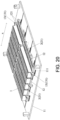
- the assembling method of the battery device using the battery component positioning tooling of the disclosure is as follows. As shown in FIG. 20 , the side of each battery 1 provided with the pole is placed facing down on the first positioning member 12 to form the battery group, and the first beam 21 coated with glue is inserted into the interval between the battery groups.
- the first beam 21 located in the middle is fixed by the second positioning member 13, the position is fixed, and the two adjacent first positioning members 12 on the left and the right thereof and the battery groups carried thereby are moved closer to the middle first beam 21 under the driving of the air cylinder, so that the battery group is bonded with the first beam 21. Then, the two outer first positioning elements 12 and the battery groups carried thereby are moved closer toward the direction of the middle first beam 21.
- the moving process of the two first positioning members 12 may push the inner first beam 21 and second positioning member 13 to move inward until the inner battery group is extruded, so that the relatively outer battery groups are bonded with the adjacent first beams 21.
- the battery groups are moved in a sequence from the inside out.
- the inner battery group is moved first, and the relatively outer battery groups are then sequentially moved.
- Each battery group is moved inward to implement the bonding between each battery group and the adjacent first beam 21, so that the battery group and the first beam 21 of the battery device are assembled in place.
- the assembling method of the embodiment can prevent premature curing of the glue layer on the side of the battery group installed later due to the difference in installation times of the two battery groups, prevent connection failure between the battery group and the first beam 21, and improve the assembling yield.
- the assembling method of the embodiment may adopt a manner of the air cylinders simultaneously operating, so that the assembling efficiency is higher and the connection yield is better.
- the assembling method may specifically include the following steps.
- Step 301 as shown in FIG. 2 to FIG. 7 , the first beam 21 is arranged on the positioning tooling, and the battery 1 adjacent to the first beam 21 is then arranged based on the first beam 21.
- the first beams 21 and the batteries 1 are alternately arranged along the horizontal direction by analogy until the preset required number of the batteries 1 is reached.
- Step 302 as shown in FIG. 8 , the second beam 22 is arranged.
- the second beam 22 and the first beam 21 are perpendicularly intersected and engaged with each other to separate different battery groups in the longitudinal direction.
- Step 303 as shown in FIG. 8 and FIG. 9 , the front and rear bezels 31 are installed, and the front and rear bezels 31 are connected to the two ends of the first beam 21.
- Step 304 as shown in FIG. 9 and FIG. 10 , the left and right bezels 32 are installed, the left and right bezels 32 are bonded with the two ends of the front and rear bezels 31 and are locked through bolts.
- Step 305 as shown in FIG. 10 and FIG. 11 , the box base plate 4 is installed, the box base plate 4 is bonded with the bottom of the battery 1, and the box base plate 4 and the box frame are then locked through bolts, thereby forming the box structure.
- Step 306 as shown in FIG. 11 and FIG. 12 , the assembled module is turned over, so that the box base plate 4 faces downward, the opening of the box faces upwards, and at the same time, the pole on the battery 1 is exposed, and the busbar 5 is assembled above the battery 1.
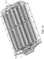
- Step 307 as shown in FIG. 13 , the electrical device 6 is arranged in a space surrounded by the front and rear bezels 31.
- Step 308 as shown in FIG. 14 , the cover plate 7 is assembled, and the cover plate 7 is sealed with the lower box to form the battery device.
- the battery device provided in the embodiment may be a battery pack.
- the base plate of the battery device may include a liquid-cooling plate and a bottom shield.
- the glue fixing between the battery group and the box frame can reduce the pressure of the battery group on the liquid-cooling plate and improve the safety and the reliability of the battery pack.
Landscapes
- Chemical & Material Sciences (AREA)
- Chemical Kinetics & Catalysis (AREA)
- Electrochemistry (AREA)
- General Chemical & Material Sciences (AREA)
- Engineering & Computer Science (AREA)
- Manufacturing & Machinery (AREA)
- Mechanical Engineering (AREA)
- Transportation (AREA)
- Life Sciences & Earth Sciences (AREA)
- Sustainable Development (AREA)
- Sustainable Energy (AREA)
- Power Engineering (AREA)
- Combustion & Propulsion (AREA)
- Aviation & Aerospace Engineering (AREA)
- Inorganic Chemistry (AREA)
- Battery Mounting, Suspending (AREA)
Abstract
Description
- The disclosure relates to the technical field of batteries, and in particular to a battery device, an assembling method and an assembling equipment thereof, and a battery component positioning tooling.
- In the conventional design, the assembling method of a battery pack is to assemble a battery box, and then place batteries into the box in groups, that is, assemble the box first, and then complete the assembly of the battery group. Therefore, the assembling process of the battery pack is relatively complicated, has low efficiency, and is difficult to implement automated production. Also, a series of unstable factors are present during the process of transferring the box and the batteries, resulting in a decrease in yield.
- The disclosure provides a battery device, an assembling method and an assembling equipment thereof, and a battery component positioning tool, which are used to improve an assembling process of the battery device and increase the production efficiency.
- According to a first aspect, the disclosure provides an assembling method of a battery device. The battery device includes a beam, a box base plate, a box bezel, and a battery. The beam, the box base plate, and the box bezel surround to form a box. The battery is disposed in the box. The assembling method includes the following steps.
- The beam, the box base plate, and the box bezel are respectively connected and assembled with the battery according to a set sequence. In the set sequence, the box base plate or at least part of the box bezel is assembled after the beam.
- According to a second aspect, the disclosure provides a battery device. The battery device is prepared by adopting the assembling method of the battery device. The battery device includes a box formed from a beam, a box bezel, and a box base plate, and a battery located in the box.
- According to a third aspect, the disclosure provides an assembling equipment of a battery device. The assembling equipment of the battery device is used to executes the steps in the assembling method of the battery device. The assembling equipment includes the following.
- A first assembling mechanism is configured to assemble and fix a beam and a battery.
- A second assembling mechanism is configured to assemble a box base plate and/or at least part of a box bezel on a component assembled and formed from the beam and the battery.
- According to a fourth aspect, the disclosure provides a battery component positioning tooling. The battery component positioning tooling is used to position at least part of components constituting a battery device during an assembling process of the battery device. The battery device includes a beam, a box base plate, a box bezel, and a battery. The beam, the box base plate, and the box bezel surround to form a box. The battery is disposed in the box.
- The battery component positioning tooling includes a carrier plate and a positioning structure located on the carrier plate. The carrier plate is used to carry at least one of the box bezel, the beam, and the battery. The positioning structure is used to position at least one of the box bezel, the beam, and the battery.
- For a better understanding of the disclosure, reference may be made to exemplary embodiments shown in the following drawings. The components in the drawings are not necessarily to scale and related elements may be omitted, or in some instances proportions may have been exaggerated, so as to emphasize and clearly illustrate the features described herein. In addition, related elements or components can be variously arranged, as known in the art. Further, in the drawings, like reference numerals designate same or like parts throughout the several views.
-
FIG. 1 is a flowchart of an assembling method of a battery device according to an embodiment of the disclosure. -
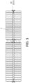
FIG. 2 is a schematic diagram of a structure of a first beam of a battery device according to an embodiment of the disclosure. -
FIG. 3 is a schematic diagram of a structure of assembling a battery based on a common structural beam in an assembling method of a battery device according to an embodiment of the disclosure. -
FIG. 4 is a schematic diagram of a structure of assembling a heat exchange functional beam on another side of a battery group in an assembling method of a battery device according to an embodiment of the disclosure. -
FIG. 5 is a schematic diagram of a structure of continuing to assemble a battery based on a heat exchange functional beam in an assembling method of a battery device according to an embodiment of the disclosure. -
FIG. 6 is a schematic diagram of a structure of installing a second common structural beam in an assembling method of a battery device according to an embodiment of the disclosure. -
FIG. 7 is a schematic diagram of a structure after installing a first beam and a battery in place in an assembling method of a battery device according to an embodiment of the disclosure. -
FIG. 8 is a schematic diagram of a structure after installing a second beam in place in an assembling method of a battery device according to an embodiment of the disclosure. -
FIG. 9 is a schematic diagram of a structure after installing front and rear bezels in place in an assembling method of a battery device according to an embodiment of the disclosure. -
FIG. 10 is a schematic diagram of a structure after installing left and right bezels in place in an assembling method of a battery device according to an embodiment of the disclosure. -
FIG. 11 is a schematic diagram of a structure after installing a base plate in place in an assembling method of a battery device according to an embodiment of the disclosure. -
FIG. 12 is a schematic diagram of a structure after installing a busbar in place in an assembling method of a battery device according to an embodiment of the disclosure. -
FIG. 13 is a schematic diagram of a structure after installing an electrical device in place in an assembling method of a battery device according to an embodiment of the disclosure. -
FIG. 14 is a schematic diagram of a structure after installing a cover plate in place in an assembling method of a battery device according to an embodiment of the disclosure. -
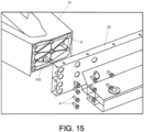
FIG. 15 is a schematic diagram of an exploded structure of a connecting part of left and right bezels and front and rear bezels in a battery device according to an embodiment of the disclosure. -
FIG. 16 is a schematic diagram of a structure of a connecting part of left and right bezels and front and rear bezels in a battery device according to an embodiment of the disclosure. -
FIG. 17 is a schematic diagram of a structure of an assembling process of a battery and a first beam in an assembling method of a battery device according to an embodiment of the disclosure. -
FIG. 18 is a schematic diagram of a structure of an assembling process of a battery and a first beam in an assembling method of a battery device according to another embodiment of the disclosure. -
FIG. 19 is a schematic diagram of a structure of an assembling process of a battery and a first beam in an assembling method of a battery device according to another embodiment of the disclosure. -
FIG. 20 is a schematic diagram of a structure of a battery component positioning tooling when assembling a battery and a first beam according to an embodiment of the disclosure. - The technical solutions in the exemplary embodiments of the disclosure will be described clearly and explicitly in conjunction with the drawings in the exemplary embodiments of the disclosure. The description proposed herein is just the exemplary embodiments for the purpose of illustrations only, not intended to limit the scope of the disclosure, so it should be understood that and various modifications and variations could be made thereto without departing from the scope of the disclosure.
- In the description of the present disclosure, unless otherwise specifically defined and limited, the terms "first", "second" and the like are only used for illustrative purposes and are not to be construed as expressing or implying a relative importance. The term "plurality" is two or more. The term "and/or" includes any and all combinations of one or more of the associated listed items.
- In particular, a reference to "the" object or "a" and "an" object is intended to denote also one of a possible plurality of such objects. Unless otherwise defined or described, the terms "connect", "fix" should be broadly interpreted, for example, the term "connect" can be "fixedly connect", "detachably connect", "integrally connect", "electrically connect" or "signal connect". The term "connect" also can be "directly connect" or "indirectly connect via a medium". For the persons skilled in the art, the specific meanings of the abovementioned terms in the present disclosure can be understood according to the specific situation.
- Further, in the description of the present disclosure, it should be understood that spatially relative terms, such as "above", "below" "inside", "outside" and the like, are described based on orientations illustrated in the figures, but are not intended to limit the exemplary embodiments of the present disclosure.
- In the context, it should also be understood that when an element or features is provided "outside" or "inside" of another element(s), it can be directly provided "outside" or "inside" of the other element, or be indirectly provided "outside" or "inside" of the another element(s) by an intermediate element.
- At present, with the rise of electric vehicles, the new energy battery device used in the field of electric vehicles has developed rapidly. The battery device generally includes an external sealed box and a battery group located in the box. The battery group constitutes of square batteries, such as square lithium-ion batteries. The box of the battery device is generally an independent product, which is assembled and integrated by a third party and then supplied to a battery manufacturer, and the battery manufacturer completes the battery boxing operation to assemble to form the battery device product. Therefore, the production cycle of the battery device is relatively long, the efficiency is relatively low, the production process is not conducive to automated production, and quality issues frequently occur in the initial integration stage of the box and the assembly stage of the battery, which is not conducive to improving the production yield of the battery device. In addition, the current box of the battery device is mainly assembled by welding, which is easy to cause a series of issues affecting quality, such as dimensional thermal deformation deviation, low primary airtight pass rate, reduced performance of secondary repair welding materials, difficult removal of metal residues on bezels after welding, and system insulation failure caused by welding slags/welding seams.
- In view of this, the disclosure provides a battery device, an assembling method and an assembling equipment thereof, and a battery component positioning tooling, which are used to improve the assembling process of the battery device and improve the assembling efficiency and the yield of the battery device.
- According to a first aspect, the disclosure provides an assembling method of a battery device. Referring to
FIG. 2 to FIG. 11 , the battery device includes abeam 2, abox base plate 4, abox bezel 3, and abattery 1. Thebeam 2, thebox base plate 4, and thebox bezel 3 surround to form a box, and thebattery 1 is disposed in the box. 'Surround to form a box' refers to surrounding to form the shape of the box. The box is not necessarily a complete sealed structure. For example, thebox bezel 3 may include front andrear bezels 31 and left andright bezels 32, and thebeam 2 may include afirst beam 21 and asecond beam 22. The box formed from thebeam 2, thebox base plate 4, and thebox bezel 3 refers to a box form with an upper opening without a cover. Specifically, the assembling method of the battery device provided in the disclosure includes the following steps: - The
beam 2, thebox base plate 4, and thebox bezel 3 are respectively connected and assembled with thebattery 1 according to a set sequence. In the set sequence, thebox base plate 4 or at least part of thebox bezel 3 is assembled after thebeam 2. For example, as shown inFIG. 2 to FIG. 10 , thebeam 2 and thebox bezel 3 may be connected to thebattery 1 first, and thebox base plate 4 that is not connected to thebattery 1 may be then further installed, as shown inFIG. 11 . Alternatively, thebeam 2 and thebox base plate 4 are connected to thebattery 1 first, and thebox bezel 3 that is not connected to thebattery 1 is then installed. - The assembling method of the battery device provided in the disclosure does not need to assemble the box of the battery device in advance, but integrates the assembling process of the
battery 1 with the assembling steps of the box. Firstly, thebattery 1 is connected to a partial structure (thebeam 2, thebox bezel 3, or the box base plate 4) for constituting the box, and a remaining part for constituting the box is then installed to form the complete box. After assembling thebattery 1, the complete box is assembled and formed, so that the entire assembling process is seamlessly connected and is not easy to produce factors that affect the yield of the battery device. For example, it is only necessary to connect thebattery 1 to a part of the box structure when assembling thebattery 1, and thebattery 1 does not need to be assembled by adopting overpressure and being vertically inserted into the box, and is not limited by the box structure, which is beneficial to improving the assembling efficiency and the yield. Moreover, non-welding forms such as bonding and/or fastener connection may be adopted between the successively installed parts of the box structure, which may prevent issues such as poor consistency of the box caused by welding, and poor assembly and insulation failure caused by welding slags, welding seams, etc. compared with the manner of forming the box by welding in advance and then assembling thebattery 1. In addition, through the innovation of the assembling manner of integrating thebattery 1 to the battery device, the assembling method of the disclosure breaks the traditional independent manufacturing mode of the box, highly integrates the box manufacturing processing and the system assembling processing, has simpler assembling process and processing, and can implement the seamless connection of the entire assembling process, which is conducive to building a fully automated production line, improving the production efficiency, implementing high-speed manufacturing and high-yield manufacturing, and reducing manufacturing costs. In addition, if thebox bezel 3 and thebox base plate 4 surround to form the box, and thebattery 1 is already assembled into the box, and thebeam 2 is then assembled, at this time, due to the assembly tolerance, thebeam 2 may not be able to be assembled into the box. If the beam is forcibly plugged in, the box may be deformed. If thebattery 1 is extruded, thebattery 1 may be deformed or damaged, which affects the life of thebattery 1. In the assembling solution of the disclosure, thebeam 2 is assembled before thebox base plate 4 or at least part of thebox bezel 3, and thebeam 2 is not assembled last, that is, before thebeam 2 is assembled, the complete box is not formed, so that the limitation of the assembling space of the box structure to thebeam 2 can be reduced, which may prevent the above assembling issues, thereby further improving the assembling efficiency and the yield. - In some embodiments, respectively connecting and assembling the
beam 2, thebox base plate 4, and thebox bezel 3 with thebattery 1 according to the set sequence may specifically include the following steps, as shown inFIG. 1 . - In
Step 101, as shown inFIG. 2 to FIG. 10 , thebeam 2 and thebox bezel 3 are assembled and fixed with thebattery 1. - In
Step 102, as shown inFIG. 11 , thebox base plate 4 is then assembled. - The stability of a component formed by assembling and fixing the
box bezel 3 and thebeam 2 with thebattery 1 is better, and the relative positions between eachbattery 1 and a box frame are determined first, which is beneficial to the installation operation of the subsequent remaining partial structures (for example, thebox base plate 4 and a busbar), and is beneficial to improving the overall assembling yield and efficiency of the final battery device. - In some embodiments, in
Step 101, assembling and fixing thebeam 2 and thebox bezel 3 with thebattery 1 specifically includes the following. As shown inFIG. 10 andFIG. 11 , one side of thebattery 1 where a pole is located faces the ground to be assembled and fixed with thebox bezel 3 and thebeam 2. Exemplarily, thebattery 1 may be a lithium-ionsquare battery 1 and is specifically a hexahedron. The side of thebattery 1 where the pole is located is away from thebox base plate 4, faces a cover plate of the battery device, and is used to arrange a busbar 5 and connect to a harness plate component through the busbar 5. - Further, in
Step 102, assembling thebox base plate 4 may include the following implementation. - As shown in
FIG. 10 andFIG. 11 , thebox base plate 4 is bonded and fixed with one side of thebattery 1 away from the pole. - Further, the assembling method of the battery device may further include the following steps.
- In Step 103, as shown in
FIG. 11 andFIG. 12 , a module assembled with thebox base plate 4 is turned over as a whole, and the busbar 5 is assembled on the side of thebattery 1 where the pole is provided. - In the embodiment, the side of the
battery 1 where the pole is located faces the ground to be assembled with the box frame, that is, thebattery 1 and the box frame are inverted for connection and assembly. In this way, after connecting and assembling thebattery 1 with the box frame, the assembly of thebox base plate 4 may be directly performed without moving the component consisting of thebattery 1 and the box frame. Then, the component is turned over to assemble structures such as the busbar 5, the harness plate component, and acover plate 7 of the box. Since thebattery 1 and the box frame are inverted when assembling thebox base plate 4, the assembling operation of thebox base plate 4 is simple, such as installing a locking member on one side of thebox base plate 4 and other operations, which are very convenient. - In some embodiments, in
Step 101, assembling and fixing thebeam 2 and thebox bezel 3 with thebattery 1 specifically includes the following. - A positioning tooling is provided to assemble and connect the
box bezel 3, thebeam 2, and thebattery 1 on the positioning tooling. The positioning tooling is provided with a positioning structure, and the positions of thebox bezel 3, thebeam 2, and/or thebattery 1 are positioned through the positioning structure. - In the embodiment, the positioning tooling may not only carry assembly parts, but may also position the assembly parts. For example, the relative positions of the
beam 2, thebox bezel 3, and eachbattery 1 may be positioned through the positioning tooling, thereby improving the assembling efficiency and ensuring the consistency and the yield of assembled components. - For example, as shown in
FIG. 2 to FIG. 10 , firstly, the box frame and thebattery 1 are assembled on the positioning tooling. Further, as shown inFIG. 10 andFIG. 11 , the assembling steps of thebox base plate 4 may also be performed on the positioning tooling, that is, after the box frame and thebattery 1 are assembled and connected on the positioning tooling. There is no need to move or turn over the box frame and thebattery 1, and thebox base plate 4 is directly bonded and fixed with the side of thebattery 1 away from the pole to complete the assembly of the box. As shown inFIG. 12 to FIG. 14 , the box may be turned over, so that one side of the opening of the box faces upwards to facilitate further assembly of structures such as the busbar 5, the harness plate component, an electrical device 6, and thecover plate 7. - In some embodiments, after the
beam 2, thebox bezel 3, and thebattery 1 are assembled and fixed, in a direction perpendicular to a large surface of the battery, there is a gap between at least one large surface of eachbattery 1 and an adjacent structure. Thebattery 1 is a hexahedron. The large face of the battery is the two opposite surfaces with the largest area. In this way, the battery can be prevented from being extruded, and the further extrusion of the batteries due to expansion and deformation when working can be alleviated, thereby improving the safety performance of the battery. Exemplarily, there may be an interval between two adjacent large surfaces of the batteries, there may be an interval between the large surface of the battery and an adjacent spacer, or there may be an interval between the large surface of the battery and the adjacent box frame. - At present, the conventional assembling process is to assemble the box in advance and then put the battery into the box. Generally, it is necessary to adopt a clamping tooling to pressurize the battery group in the direction perpendicular to the large surface of the battery, and then put the over pressurized battery group into different cavities of the box. During the assembling process and after assembly, each battery is subjected to a certain extrusion force in the direction perpendicular to the large surface of the battery, and the battery is prone to expansion and deformation during charging and discharging processes, especially in the direction perpendicular to the large surface of the battery. As such, the battery device prepared by adopting the conventional method is prone to defects or even safety issues due to the force and large changes in deformation during the usage process. The assembling process of the embodiment integrates the assembling process of the battery with the assembling steps of the box, and does not require the operation of over pressing the battery group into the box. Also, the positioning tooling may be adopted during the assembling process to ensure the relative positions of each battery group and the box frame, thereby ensuring that each battery is not subjected to the extrusion force in the direction perpendicular to the large surface of the battery. Therefore, the assembling process of the battery device provided in the embodiment can reduce or prevent the extrusion of each battery in the direction perpendicular to the large surface of the battery during the assembling process and after assembly, thereby increasing the service life of the battery device, and reducing the probability of safety issues of the battery device.
- Exemplarily, in
Step 101, assembling and fixing thebeam 2 and thebox bezel 3 with thebattery 1 may specifically include the following. - A spacer is disposed on one side of the large surface of at least the
battery 1, and thebatteries 1 are then sequentially assembled along the direction perpendicular to the large surface of the battery. There is a gap between thebattery 1 that is assembled later and theadjacent battery 1 that is assembled earlier. In this way, eachbattery 1 may be arranged along the direction perpendicular to the large surface of the battery, and there is a certain interval between eachbattery 1 and theadjacent battery 1 or the adjacent spacer. For example, the spacer is disposed on one side of the large surface of eachbattery 1, so there is the spacer between any twoadjacent batteries 1. One side of the spacer is bonded with the large surface of one battery, and the interval is provided between the other side and the large surface of another battery. Therefore, there is no extrusion between theadjacent batteries 1, and the interval and the spacer can provide buffers for the expansion and deformation of the battery when thebattery 1 is working to prevent poor extrusion or other safety issues due to a large deformation of thebattery 1. - In some embodiments, in
Step 101, assembling and fixing thebeam 2 and thebox bezel 3 with thebattery 1 may include the following steps. - In Step 201, as shown in
FIG. 2 to FIG. 8 , firstly, thebattery 1 and thebeam 2 are bonded and fixed. - In Step 202, as shown in
FIG. 9 andFIG. 10 , thebox bezel 3 is then connected to thebeam 2 to form the box frame. - By adopting the assembling method in the embodiment, each
battery 1 may be pre-fixed through thebeam 2, which facilitates the subsequent installation of thebox bezel 3, thebox base plate 4, and other structures. - In some embodiments, Step 201, bonding and fixing the
battery 1 and thebeam 2 may include the following. - As shown in
FIG. 2 to FIG. 7 , a first side surface of thebattery 1 and thefirst beam 21 are bonded and fixed, and the first side surface of thebattery 1 is perpendicular to the large surface of the battery. - In the manufactured battery device, the
batteries 1 are accommodated in the cavities of the box in groups, and thebatteries 1 in the battery group are arranged along the direction perpendicular to the large surface of the battery. Through bonding and fixing the first side surface of eachbattery 1 and thefirst beam 21, eachbattery 1 is based on thefirst beam 21 and is arranged along an extension direction of thefirst beam 21 to form the battery group. Thebatteries 1 in each battery group may all be connected and fixed with the adjacentfirst beam 21, thereby facilitating subsequent installation of other structures and improving the overall stability of the battery device. - Specifically, the
batteries 1 in the battery group may be sequentially respectively bonded with thefirst beam 21, or thebatteries 1 may be arranged into groups first and then uniformly pasted onto thefirst beam 21, which may be determined according to actual requirements. - Exemplarily, as shown in
FIG. 2 to FIG. 7 , bonding and fixing the first side surface of thebattery 1 and thefirst beam 21 may specifically include the following implementation. Thefirst beam 21 includes a commonstructural beam 211 and a heat exchangefunctional beam 212. The commonstructural beam 211 is only used as a structural bezel, and the heat exchangefunctional beam 212 is configured as a liquid-cooling plate. In addition to being used as the structural bezel, a heat exchange medium may be circulated inside for the heat exchange of thebattery 1. Along a direction perpendicular to thefirst beam 21, the commonstructural beam 211 and the heat exchangefunctional beam 212 are alternately disposed. Thebattery 1 includes two opposite first side surfaces, one first side surface is bonded and fixed with the commonstructural beam 211, and the other first side fixed to is bonded and fixed with the heat exchangefunctional beam 212. - Because the common
structural beam 211 has high structural strength, and there is no heat exchange flow channel inside, there is no safety risk such as liquid leakage, so it is beneficial to strengthening the strength and the stability of the box frame. For example, the commonstructural beam 211 may be connected to thebox base plate 4 or thebox bezel 3 through a fastener. The heat exchangefunctional beam 212 may exchange heat with theadjacent battery 1, thereby improving the working efficiency and the yield of thebattery 1. In the embodiment, through disposing the commonstructural beam 211 on one side of each battery group and disposing the heat exchangefunctional beam 212 on the other side, the structural strength and the working performance of the battery device can be simultaneously improved with significant beneficial effects. Of course, for the battery group located at the end in the direction perpendicular to thefirst beam 21, one of the first side surfaces thereof is bonded with thefirst beam 21, and another first side surface may not be bonded with thefirst beam 21, but be directly in contact with thebox bezel 3, that is, for the battery group located at the end in the direction perpendicular to thefirst beam 21, only one side is bonded with the commonstructural beam 211 or the heat exchangefunctional beam 212. Preferably, one side of the battery group at the end is bonded with the heat exchangefunctional beam 212. - Further, in Step 201, bonding and fixing the
battery 1 and thebeam 2 also includes the following. As shown inFIG. 8 , after bonding and fixing the first side surface of thebattery 1 and thefirst beam 21, thesecond beam 22 is assembled. Thesecond beam 22 is perpendicular to thefirst beam 21, and thesecond beam 22 is snap-fitted with thefirst beam 21. - Specifically, the
second beam 22 is perpendicular to the arrangement direction of eachbattery 1 in the battery group and is parallel to the large surface of thebattery 1. Through thesecond beam 22 and thefirst beam 21 intersecting and being perpendicular to each other, multiple regions may be separated, so that different battery groups may be separated into different regions. - In some embodiments, in Step 202, the step of connecting the
box bezel 3 and thebeam 2 to form the box frame specifically includes the following implementation. - As shown in
FIG. 8 ,FIG. 9 , andFIG. 10 , the front andrear bezels 31 are assembled first, and the left andright bezels 32 are then assembled. The front andrear bezels 31 are respectively located at two ends of thefirst beam 21. The left andright bezels 32 extend in the same direction as thefirst beam 21. - Exemplarily, surfaces of the left and
right bezels 32 facing an inner side of the box are bonded with end surfaces of the front andrear bezels 31. - The left and
right bezels 32 are used to sheath the end surfaces of the front andrear bezels 31, and may seal the ends of the front andrear bezels 31. If the left andright bezels 32 are installed first, the front andrear bezels 31 need to be inserted into a spacing defined by the left andright bezels 32, which is not easy to assemble, and since there is a sealant between the ends of the front andrear bezels 31 and the left andright bezels 32, the front and rear bezels that are installed later are prone to glue spreading. Installing the front andrear bezels 31 first and then installing the left andright bezels 32 can not only prevent glue spreading, but also facilitate the operation of squeezing excessive glue along a direction perpendicular to a contact surface of the two, which is conducive to the bonding and fixing strength and the sealing yield of the two. - Exemplarily, in Step 202, connecting the
box bezel 3 to thebeam 2 to form the box frame specifically includes the following. - As shown in
FIG. 15 , the ends of the front andrear bezels 31 are provided with a glue groove, and asealant 8 is disposed in the glue groove. In this way, it is convenient to accommodate thesealant 8 and define the bonding region of thesealant 8. For example, the front andrear bezels 31 are provided with a cavity for weight reduction, and the ends of the front andrear bezels 31 are provided with acavity opening 310. The glue groove may be disposed around thecavity opening 310, so that the cavity opening 310 of the front andrear frames 31 may be sealed by thesealant 8 to improve the air tightness of the battery device. - Further, when the left and
right bezels 32 are installed, the surfaces of the left andright bezels 32 facing the inner side of the box and the end surfaces of the front andrear bezels 31 are bonded by thesealant 8 and locked by afastener 9. In this way, thefastener 9 may further ensure the connection strength of the front andrear bezels 31 and the left andright bezels 2, thereby ensuring the structural strength of the entire battery device. - Exemplarily, connecting the
box bezel 3 to thebeam 2 to form the box frame also includes the following. - As shown in
FIG. 16 , the end surfaces of the left andright bezels 32 are provided with cavity openings. The cavity openings on the end surfaces of the left andright bezels 32 are sealed by glue to improve the air tightness of the battery device and prevent phenomenon such as eolian sound when the battery device is applied in a driving environment. - For example, a
styrofoam 10 may be specifically adopted to block the cavity openings of the end surfaces of the left andright bezels 32. - Exemplarily, the steps of assembling the front and
rear bezels 31 may specifically include the following situation. - As shown in
FIG. 2 andFIG. 9 , the two ends of thefirst beam 21 are provided withadapters 20. The front andrear bezels 31 are provided with slots for inserting and matching with theadapters 20. Theadapters 20 at the two ends of thefirst beam 21 are inserted into the slots of the front andrear bezels 31. - Exemplarily, the
adapter 20 may be inserted into a main body of thefirst beam 21 and locked through a locking member. For example, theadapter 20 may be T shaped, wherein a vertical structure of the T shape is inserted into the cavity of the main body of thefirst beam 21, and a horizontal structure of the T shape is inserted into the slots of the front andrear bezels 31. - For example, as shown in
FIG. 7 andFIG. 9 , thefirst beam 21 includes the commonstructural beam 211 and the heat exchangefunctional beam 212. Theadapters 20 are provided at two ends of the commonstructural beam 211 to connect to the front andrear bezels 31. Two ends of the heat exchangefunctional beam 212 are provided with a flow channel inlet/outlet 200 for connecting to a heat exchange medium pipe. - It should be noted that in the disclosure, the front and
rear bezels 31 include two side bezels located at front and rear ends of a cavity frame and are oppositely disposed. Similarly, the left andright bezels 32 includes two opposite side bezels at left and right ends of the cavity frame. - In some embodiments, in Step 201, bonding and fixing the
battery 1 and thebeam 2 may specifically include the following implementation. - As shown in
FIG. 17 , thebeam 2 is first arranged on the positioning tooling, and thebattery 1 is then installed in a region surrounded by thebeam 2, so that thebattery 1 is bonded with theadjacent beam 2. For example, thefirst beam 21 and thesecond beam 22 are first arranged to surround to form multiple regions, and thebattery 1 is then installed in each region. In this way, rapid positioning can be facilitated, which is conducive to further improving the work efficiency. - In other embodiments, in Step 201, bonding and fixing the
battery 1 and thebeam 2 may specifically include the following implementation. - As shown in
FIG. 18 , thebattery 1 is first arranged on the positioning tooling, and thebeam 2 is then installed between thebatteries 1 and is bonded and fixed with theadjacent battery 1. For example, multiple groups of thebatteries 1 are first arranged on the positioning tooling, and thefirst beam 21 and thesecond beam 22 are then arranged between the battery groups to separate different battery groups. In this way, the installation of the battery group is facilitated, which is beneficial to implementing that eachbattery 1 is not extruded in the direction perpendicular to the large surface. In addition, the two opposite sides of the beam are usually coated with glue to bond with different battery groups. If the battery groups on two sides of the beam are successively installed, there may be poor bonding caused by a glue layer being cured when installing the battery group later. By adopting the assembling method of the embodiment, two surfaces of the beam may be simultaneously bonded with the battery groups on two sides, thereby preventing the above issue. - In other embodiments, in Step 201, bonding and fixing the
battery 1 and thebeam 2 may specifically include the following implementation. - As shown in
FIG. 19 , thebatteries 1 and thebeams 2 are alternately arranged on the positioning tooling, and theadjacent battery 1 andbeam 2 are bonded and fixed. In this way, the installation operation of thebattery 1 and thebeam 2 is very convenient, which is beneficial to improving the bonding yield between thebattery 1 and thebeam 2 to strengthen the overall structural strength. - For example, firstly, the
first beam 21 is arranged on the positioning tooling, and thebattery 1 adjacent to thefirst beam 21 is then arranged based on thefirst beam 21. The first beams 21 and thebatteries 1 are alternately arranged along the horizontal direction by analogy until the preset required number of thebatteries 1 is reached. Then, thesecond beam 22 may be arranged to separate different battery groups in the longitudinal direction. - Alternatively, firstly, a column of
batteries 1 is arranged on the positioning tooling. The column ofbatteries 1 may be one battery group or may include two or more battery groups. Then, thefirst beam 21 adjacent to the column ofbatteries 1 is arranged based on the column ofbatteries 1. The column ofbatteries 1 and thefirst beams 21 are alternately arranged in the horizontal direction by analogy until the preset required number of thebatteries 1 is reached. Then, thesecond beam 22 may be arranged to separate the column ofbatteries 1 into the battery groups. - Of course, the assembling method of the battery device and the specific implementation thereof provided in the embodiments of the disclosure are not limited to the examples in the foregoing embodiments. For example, it is also possible to first bond the
battery 1 to thebox base plate 4, and then assemble the box frame structures such as thebeam 2 and thebox bezel 3. At this time, thebox base plate 4 is preferably provided with a positioning part of eachbattery 1. Thebattery 1 is preferably placed upright and bonded with thebox base plate 4. Alternatively, thebattery 1, thebeam 2, and a part of the box bezel 3 (for example, front and rear bezels 301) may be assembled and fixed first, thebox base plate 4 is then assembled, and the other part of the box bezel 3 (for example, left and right bezels 302) is finally assembled. The selection of the specific assembling manner of the disclosure may be determined according to the actual operation requirements. - According to a second aspect, the disclosure further provides a battery device. The battery device is prepared by adopting the assembling method of the battery device. Specifically, as shown in
FIG. 8 ,FIG. 9 ,FIG. 10 , andFIG. 11 , the battery device includes the box formed from thebeam 2, thebox bezel 3, and thebox base plate 4, and thebattery 1 located in the box. - Exemplarily, the
box bezel 3 and thebox base plate 4 and thebox bezel 3 and thebeam 2 are all connected in a non-welding manner. - Specifically, in the battery device provided in the disclosure, different parts (the
beam 2, thebox bezel 3, or the box base plate 4) for constituting the box structure are directly integrated and assembled with thebattery 1. Therefore, the entire assembling process is seamlessly connected, the assembling process and the processing are simpler, the degree of automation is high, and it is not easy to produce factors that affect the product yield of the battery device, which may improve the consistency and the yield of the assembly of the battery device. In addition, it is only necessary to connect thebattery 1 to a part of the box structure when assembling thebattery 1, and thebattery 1 does not need to be assembled by adopting overpressure and being vertically inserted into the box, and is not limited by the box structure, which is beneficial to improving the assembling efficiency and the yield. Moreover, non-welding forms such as bonding and/or fastener connection may be adopted between the successively installed parts of the box structure, which may prevent issues such as poor consistency of the box caused by welding, and poor assembly and insulation failure caused by welding slags, welding seams, etc. compared with the manner of forming the box by welding in advance and then assembling thebattery 1, which can further improve the yield of the battery device. - According to a third aspect, based on the assembling method of the battery device provided in the disclosure, the disclosure also provides an assembling equipment for a battery device. The assembling equipment is used to execute the steps of the assembling method of the battery device. The assembling equipment includes the following.
- A first assembling mechanism is configured to assemble and fix the beam and the battery.
- A second assembling mechanism is configured to assemble the box base plate and/or at least part of the box bezel on the component assembled and formed from the beam and the battery.
- Specifically, the assembling equipment of the battery device provided in the embodiment is used to execute the steps in the assembling method of the battery device, which can implement the automation of the whole process assembling operation of the entire battery device, effectively improve the production efficiency of the battery device, and improve the assembling yield of the battery device.
- For example, the first assembling mechanism may be configured to sequentially bond and fix the beam and the box bezel to the battery on the positioning tooling; and the second assembling mechanism may be configured to install the box base plate on the side of the battery away from the pole. Alternatively, the first assembling mechanism may be configured to bond and fix the beam and a part of the box bezel to the battery on the positioning tooling; and the second assembling mechanism may be configured to install the box base plate and another part of the box bezel. Of course, in the disclosure, the specific operation procedures and the assembling processing executed by the first assembling mechanism and the second assembling mechanism may also include multiple implementations, which are not limited to the foregoing embodiments and may be determined according to actual conditions.
- In addition, the assembling equipment of the battery device provided in the disclosure is not limited to the above structure. For example, the assembling equipment may also include a third assembling mechanism, which is used to further execute operations such as assembling a busbar, a cover plate, etc. after installing the box and the battery.
- Specifically, the battery device and the assembling equipment of the battery device provided in the disclosure have the same inventive concept, the same or corresponding embodiments, and beneficial effects as the assembling method of the battery device provided in the disclosure, which will not be repeated in the disclosure.
- According to a fourth aspect, based on the assembling method of the battery device provided in the disclosure, the disclosure provides a battery component positioning tooling. The battery component positioning tooling is used to position at least part of components constituting the battery device during the assembling process of the battery device. As shown in
FIG. 20 , the battery device includes thebeam 2, the box base plate, the box bezel, and thebattery 1. Thebeam 2, the box base plate, and the box bezel surround to form the box. Thebattery 1 is disposed in the box. The battery component positioning tooling includes acarrier plate 11 and a positioning structure located on thecarrier plate 11. Thecarrier plate 11 is used to carry at least one of the box bezel, thebeam 2, and thebattery 1. The positioning structure is used to position at least one of the box bezel, thebeam 2, and thebattery 1. - The battery component positioning tooling provided in the embodiment may be used to carry and position assembly parts such as the
beam 2, the box bezel, and/or thebattery 1 during the assembling process of the battery device, which is beneficial to positioning the relative positions of thebeam 2, the box bezel, and eachbattery 1, thereby improving the assembling efficiency and ensuring the consistency and the yield of the assembled components. - In some embodiments, as shown in
FIG. 20 , the positioning structure includes afirst positioning member 12, and thefirst positioning member 12 is used to carry and position thebattery 1. Thebattery 1 is an important component of the battery device. The battery device generally includes multiple groups ofbatteries 1, and each group ofbatteries 1 includesmultiple batteries 1. The position of eachbattery 1 in the battery device is well positioned, which is the key to improving the assembling efficiency of the battery device. In the embodiment, setting thefirst positioning member 12 is beneficial to fixing the relative positions between thebatteries 1 and between thebattery 1 and the box bezel and the beam, thereby improving the assembling efficiency and the yield. - Exemplarily, the
first positioning member 12 includes a batterypole positioning part 121, and the batterypole positioning part 121 is used to position the pole of thebattery 1. For example, the pole of the battery is convex relative to the surface of thebattery 1. The batterypole positioning part 121 may be a slot matching a protruding part of the pole. Through inserting the protruding part of the pole of eachbattery 1 into the corresponding slot, eachbattery 1 may be pre-positioned. - Specifically, during the assembling process of the battery device, the side of the
battery 1 provided with the pole is placed facing down on thefirst positioning member 12. Thebattery 1, thebeam 2, and the box bezel may be assembled in an inverted manner, so that after assembling thebattery 1, thebeam 2, and the box bezel, the box base plate may be directly bonded and fixed to the side of thebattery 1 away from the pole. Since thebattery 1, thebeam 2, and the box bezel are all inverted at this time, and the box base plate is installed directly above the structures, which is beneficial to the installation operation. For example, the box base plate may be easily locked with thebeam 2 by adopting a locking member. - In some embodiments, as shown in
FIG. 20 , thebeam 2 includes thefirst beam 21, and thebatteries 1 are arranged into groups along the extension direction of thefirst beam 21. The positioning structure includes at least onefirst positioning member 12, and eachfirst positioning member 12 is used to carry one battery group and position thebatteries 1 in the battery group, so that eachfirst positioning member 12 may determine the relative positions between thebatteries 1 in the battery group, and then fix the relative positions of thefirst positioning members 12. That is, the positioning of allbatteries 1 in the entire battery device may be completed. It should be noted that in the embodiment of the battery component positioning tooling, the battery group refers to the battery group formed from the column ofbatteries 1 arranged along the extension direction of thefirst beam 21, instead of the battery group formed by dividing the batteries in the box of the battery device in the conventional technology. - Exemplarily, the positioning structure includes at least two
first positioning members 12 arranged along a first direction x, the at least twofirst positioning members 12 are disposed at an interval from each other, and the interval between the adjacentfirst positioning members 12 allows thefirst beam 21 to be placed. - Exemplarily, the
first beam 21 may include the common structural beam and the heat exchange functional beam. The common structural beams and the heat exchange functional beams are alternately arranged. For the specific arrangement, reference may be made to the description of the relevant part of the embodiment of the assembling method of the battery device, which is not repeated here. - Specifically, the
first beams 21 and the battery groups are alternately arranged. The adjacent battery groups are separated through thefirst beam 21. During the assembling process of the battery device, each battery group may be positioned first through thefirst positioning member 12, and thefirst beam 12 is then inserted between the adjacentfirst positioning members 12, so that thefirst beam 21 is located between the adjacent battery groups, thereby implementing the assembly and the positioning of the battery group and thefirst beam 21. - Exemplarily, the positioning structure further includes a first driving mechanism. The first driving mechanism is used to drive the
first positioning member 12 to slide along the first direction x. Specifically, the first direction x is perpendicular to the extension direction of thefirst beam 21. Through driving thefirst positioning member 12 to slide along the first direction x, a spacing between the adjacentfirst positioning members 12 or a distance between the adjacentfirst beam 21 and battery group may be adjusted, which facilitates the assembling operation and improves the assembling efficiency and the yield. For example, when installing the battery group and thefirst beam 21, in order to prevent the glue layer rubbing between the battery group and thefirst beam 21, a certain gap may be reserved between the adjacent battery group andfirst beam 21 before being placed on thecarrier plate 11. Then, through driving thefirst positioning member 12 below the battery group to move, the distance between the battery group and thefirst beam 21 is adjusted to complete a bonding operation between the battery group and thefirst beam 21. - Exemplarily, the first driving mechanism is an air cylinder. The air cylinder is disposed on one side of the
carrier plate 11 away from thefirst positioning member 12 and is in driving connection with thefirst positioning member 12. That is, the air cylinder is located below thecarrier plate 11, so that the space above thecarrier plate 11 may be saved, which facilitates the assembling operation above thecarrier plate 11. - In some embodiments, as shown in
FIG. 20 , the positioning structure further includes asecond positioning member 13, and thesecond positioning member 13 is used to engage and position the two ends of thefirst beam 21 in the extension direction. For example, thesecond positioning member 13 may include a pair ofsnaps 131, and the pair ofsnaps 131 are symmetrically disposed for respectively engaging with the two ends of thefirst beam 21. The positioning of thefirst beam 21 through thesecond positioning member 13 is beneficial to further improving the assembling efficiency and the yield of the battery device. - Exemplarily, the positioning structure includes at least two
second positioning members 13, wherein at least part of thesecond positioning members 13 may be slidably assembled on thecarrier plate 11 along the first direction x. For example, thecarrier plate 11 is provided with a pair of slidinggrooves 111 matching with the pair ofsnaps 131, and the pair ofsnaps 131 may slide along the pair of slidinggrooves 111. Thesecond positioning member 13 is slidable to easily adjust the distance between the battery group and thefirst beam 21, which is beneficial to the assembling operation between the battery group and thefirst beam 21. - For example, the
second positioning member 13 for fixing the middlefirst beam 21 is fixed relative to thecarrier plate 11, and the othersecond positioning members 13 are slidable relative to thecarrier plate 11. In this way, when assembling the battery group and thefirst beam 21, the positioning may be based on the middlefirst beam 21 to drive the battery groups to move from two sides toward the middlefirst beam 21, thereby implementing the extrusion and the bonding of thefirst beam 21 and the battery group, so that thefirst beam 21 and the battery group are assembled in place. - In a specific implementation, the assembling method of the battery device using the battery component positioning tooling of the disclosure is as follows. As shown in
FIG. 20 , the side of eachbattery 1 provided with the pole is placed facing down on thefirst positioning member 12 to form the battery group, and thefirst beam 21 coated with glue is inserted into the interval between the battery groups. Thefirst beam 21 located in the middle is fixed by thesecond positioning member 13, the position is fixed, and the two adjacentfirst positioning members 12 on the left and the right thereof and the battery groups carried thereby are moved closer to the middlefirst beam 21 under the driving of the air cylinder, so that the battery group is bonded with thefirst beam 21. Then, the two outerfirst positioning elements 12 and the battery groups carried thereby are moved closer toward the direction of the middlefirst beam 21. The moving process of the twofirst positioning members 12 may push the innerfirst beam 21 andsecond positioning member 13 to move inward until the inner battery group is extruded, so that the relatively outer battery groups are bonded with the adjacent first beams 21. By analogy, the battery groups are moved in a sequence from the inside out. The inner battery group is moved first, and the relatively outer battery groups are then sequentially moved. Each battery group is moved inward to implement the bonding between each battery group and the adjacentfirst beam 21, so that the battery group and thefirst beam 21 of the battery device are assembled in place. - Specifically, compared with the assembling method of successively installing the battery groups on the two sides of the
first beam 21, the assembling method of the embodiment can prevent premature curing of the glue layer on the side of the battery group installed later due to the difference in installation times of the two battery groups, prevent connection failure between the battery group and thefirst beam 21, and improve the assembling yield. In addition, the assembling method of the embodiment may adopt a manner of the air cylinders simultaneously operating, so that the assembling efficiency is higher and the connection yield is better. - Hereinafter, a specific implementation of the assembling method of the battery device of the disclosure is exemplified. The assembling method may specifically include the following steps.
- In Step 301, as shown in
FIG. 2 to FIG. 7 , thefirst beam 21 is arranged on the positioning tooling, and thebattery 1 adjacent to thefirst beam 21 is then arranged based on thefirst beam 21. The first beams 21 and thebatteries 1 are alternately arranged along the horizontal direction by analogy until the preset required number of thebatteries 1 is reached. - In Step 302, as shown in
FIG. 8 , thesecond beam 22 is arranged. Thesecond beam 22 and thefirst beam 21 are perpendicularly intersected and engaged with each other to separate different battery groups in the longitudinal direction. - In Step 303, as shown in
FIG. 8 andFIG. 9 , the front andrear bezels 31 are installed, and the front andrear bezels 31 are connected to the two ends of thefirst beam 21. - In Step 304, as shown in
FIG. 9 andFIG. 10 , the left andright bezels 32 are installed, the left andright bezels 32 are bonded with the two ends of the front andrear bezels 31 and are locked through bolts. - In Step 305, as shown in
FIG. 10 andFIG. 11 , thebox base plate 4 is installed, thebox base plate 4 is bonded with the bottom of thebattery 1, and thebox base plate 4 and the box frame are then locked through bolts, thereby forming the box structure. - In Step 306, as shown in
FIG. 11 andFIG. 12 , the assembled module is turned over, so that thebox base plate 4 faces downward, the opening of the box faces upwards, and at the same time, the pole on thebattery 1 is exposed, and the busbar 5 is assembled above thebattery 1. - In Step 307, as shown in
FIG. 13 , the electrical device 6 is arranged in a space surrounded by the front andrear bezels 31. - In Step 308, as shown in
FIG. 14 , thecover plate 7 is assembled, and thecover plate 7 is sealed with the lower box to form the battery device. - Specifically, the battery device provided in the embodiment may be a battery pack. The base plate of the battery device may include a liquid-cooling plate and a bottom shield. The glue fixing between the battery group and the box frame can reduce the pressure of the battery group on the liquid-cooling plate and improve the safety and the reliability of the battery pack.
- Other embodiments of the disclosure will be apparent to those skilled in the art from consideration of the specification and practice of the disclosure disclosed herein. The disclosure is intended to cover any variations, uses or adaptations of the disclosure. These variations, uses, or adaptations follow the general principles of the disclosure and include common general knowledge or conventional technical means in the art that are not disclosed in the present disclosure.
Claims (31)
- An assembling method of a battery device, wherein the battery device comprises a beam (2), a box base plate (4), a box bezel (3), and a battery (1), the beam (2), the box base plate (4), and the box bezel (3) surround to form a box, and the battery (1) is disposed in the box, the assembling method comprising:
respectively connecting and assembling the beam (2), the box base plate (4), and the box bezel (3) with the battery (1) according to a set sequence, wherein in the set sequence, the box base plate (4) or at least part of the box bezel (3) is assembled after the beam (2). - The assembling method of the battery device according to claim 1, wherein respectively connecting and assembling the beam (2), the box base plate (4), and the box bezel (3) with the battery (1) according to the set sequence comprises:
assembling and fixing the beam (2) and the box bezel (3) with the battery (1) first, and then assembling the box base plate (4). - The assembling method of the battery device according to claim 2, wherein assembling and fixing the beam (2) and the box bezel (3) with the battery (1) comprises: after assembling and fixing the beam (2) and the box bezel (3) with the battery (1), in a direction perpendicular to a large surface of the battery (1), having a gap between at least one large surface of each of the battery (1) and an adjacent structure.
- The assembling method of the battery device according to claim 3, wherein assembling and fixing the beam (2) and the box bezel (3) with the battery (1) comprises:
disposing a spacer on a large surface of at least part of batteries (1), then sequentially assembling the batteries (1) along the direction perpendicular to the large surface of the battery (1), and having a gap between a battery (1) assembled later and an adjacent battery (1) assembled earlier. - The assembling method of the battery device according to claim 2, wherein assembling and fixing the beam (2) and the box bezel (3) with the battery (1) comprises:
bonding and fixing the battery (1) and the beam (2) first, and then connecting the box bezel (3) to the beam (2) to form a box frame. - The assembling method of the battery device according to claim 5, wherein bonding and fixing the battery (1) and the beam (2) comprises:
bonding and fixing a first side surface of the battery (1) and a first beam (21), wherein the first side surface of the battery (1) is perpendicular to the large surface of the battery (1). - The assembling method of the battery device according to claim 6, wherein bonding and fixing the first side surface of the battery (1) and the first beam (21) further comprises:
along a direction perpendicular to a large surface of the first beam (21), alternately arranging a common structural beam (211) and a heat exchange functional beam (212), wherein the first beam (21) comprises the common structural beam (211) and the heat exchange functional beam (212), and the heat exchange functional beam (212) is configured as a heat exchange plate; bonding and fixing a first side surface and the common structural beam (211), and bonding and fixing another first side surface and the heat exchange functional beam (212), wherein the battery (1) comprises two opposite first side surfaces. - The assembling method of the battery device according to claim 6, wherein bonding and fixing the battery (1) and the beam (2) further comprises:
after bonding and fixing the first side surface of the battery (1) and the first beam (21), assembling a second beam (22), wherein the second beam (22) is perpendicular to the first beam (21), and the second beam (22) is snap-fitted with the first beam (21). - The assembling method of the battery device according to claim 6, wherein connecting the box bezel (3) to the beam (2) to form the box frame comprises:
assembling front and rear bezels (31) first, and then assembling left and right bezels (32), wherein the front and rear bezels (31) are respectively located at two ends of the first beam (21), and the left and right bezels (32) extend in a same direction as the first beam (21). - The assembling method of the battery device according to claim 9, wherein assembling the front and rear bezels (31) first, and then assembling the left and right bezels (32) specifically comprises:
bonding a surface of the left and right bezels (32) facing an inner side of the box and an end surface of the front and rear bezels (31). - The assembling method of the battery device according to claim 10, wherein connecting the box bezel (3) to the beam (2) to form the box frame comprises:providing a glue groove at an end of the front and rear bezels (31), and disposing a sealant (8) in the glue groove at the end of the front and rear bezels (31);when installing the left and right bezels (32), bonding the surface of the left and right bezels (32) facing the inner side of the box and the end surface of the front and rear bezels (31) through the sealant (8), and locking through a fastener (9).
- The assembling method of the battery device according to claim 9, wherein assembling the front and rear bezels (31) specifically comprises:
providing an adapter (20) at the two ends of the first beam (21), providing a slot for inserting and matching with the adapter (20) on the front and rear bezels (31), and inserting the adapter (20) at the two ends of the first beam (21) into the slot of the front and rear bezels (31). - The assembling method of the battery device according to claim 10, wherein connecting the box bezel (3) to the beam (2) to form the box frame further comprises:
providing a cavity opening on an end surface of the left and right bezels (32), and sealing the cavity opening on the end surface of the left and right bezels (32) through glue. - The assembling method of the battery device according to any one of claims 5-13, wherein assembling and fixing the beam (2) and the box bezel (3) with the battery (1) comprises:
assembling and fixing one side of the battery (1) where a pole is facing a ground with the box bezel (3) and the beam (2). - The assembling method of the battery device according to claim 14, wherein assembling and fixing the beam (2) and the box bezel (3) with the battery (1) comprises:
providing a positioning tooling, assembling and connecting the box bezel (3), the beam (2), and the battery (1) on the positioning tooling, providing a positioning structure on the positioning tooling, and positioning positions of the box bezel (3), the beam (2), and/or the battery (1) through the positioning structure. - The assembling method of the battery device according to claim 15, wherein bonding and fixing the battery (1) and the beam (2) comprises:
arranging the beam (2) on the positioning tooling first, and then installing the battery (1) in a region surrounded by the beam (2), so that the battery (1) is bonded with an adjacent beam (2). - The assembling method of the battery device according to claim 15, wherein bonding and fixing the battery (1) and the beam (2) comprises:
arranging the battery (1) on the positioning tooling first, and then installing the beam (2) between batteries (1) to be bonded with adjacent batteries (1). - The assembling method of the battery device according to claim 15, wherein bonding and fixing the battery (1) and the beam (2) comprises:
alternately arranging batteries (1) and beams (2) on the positioning tooling, and bonding and fixing adjacent batteries (1) and beams (2). - The assembling method of the battery device according to any one of claims 15-18, wherein:assembling the box base plate (4) specifically comprises:
bonding and fixing the box base plate (4) to one side of the battery (1) away from the pole;after assembling the box base plate (4), assembling the box base plate (4) further comprises:
turning over an assembled module as a whole, and assembling a busbar on one side of the battery (1) provided with the pole. - A battery device, prepared by adopting the assembling method of the battery device according to any one of claims 1-19, the battery device comprising a box formed from a beam (2), a box bezel (3), and a box base plate (4), and a battery (1) located in the box.
- The battery device according to claim 20, wherein the box bezel (3) and the box base plate (4) and the box bezel (3) and the beam (2) are both connected by adopting a non-welding manner.
- An assembling equipment of a battery device, wherein the assembling equipment of the battery device is configured to execute the steps in the assembling method of the battery device according to any one of claims 1-19, the assembling equipment comprising:a first assembling mechanism, configured to assemble and fix a beam (2) and a battery (1);a second assembling mechanism, configured to assemble a box base plate (4) and/or at least part of a box bezel (3) on a component assembled and formed from the beam (2) and the battery (1).
- A battery component positioning tooling, wherein the battery component positioning tooling is configured to position at least part of components constituting a battery device during an assembling process of the battery device; the battery device comprises a beam (2), a box base plate (4), a box bezel (3), and a battery (1), the beam (2), the box base plate (4), and the box bezel (3) surround to form a box, and the battery (1) is disposed in the box;
the battery component positioning tooling comprises a carrier plate (11) and a positioning structure located on the carrier plate (11), the carrier plate (11) is configured to carry at least one of the box bezel (3), the beam (2), and the battery (1), and the positioning structure is configured to position at least one of the box bezel (3), the beam (2), and the battery (1). - The battery component positioning tooling according to claim 23, wherein the positioning structure comprises a first positioning member (12), and the first positioning member (12) is configured to carry and position the battery (1).
- The battery component positioning tooling according to claim 24, wherein the first positioning member (12) comprises a battery pole positioning part (121), and the battery pole positioning part (121) is configured to position a pole of the battery (1).
- The battery component positioning tooling according to claim 24 or 25, wherein the beam (2) comprises a first beam (21), and batteries (1) are arranged into groups along an extension direction of the first beam (21);
the positioning structure comprises at least one of the first positioning member (12), and each of the first positioning member (12) is configured to carry a battery group and position the batteries (1) in the battery group. - The battery component positioning tooling according to claim 26, wherein the positioning structure comprises at least two first positioning members (12) arranged along a first direction (x), the at least two first positioning members (12) are arranged at an interval from each other, and the interval between the adjacent first positioning members (12) allows the first beam (21) to be placed.
- The battery component positioning tooling according to claim 27, wherein the positioning structure further comprises a first driving mechanism, and the first driving mechanism is configured to drive the first positioning member (12) to slide along the first direction (x).
- The battery component positioning tooling according to claim 28, wherein the first driving mechanism is an air cylinder, and the air cylinder is disposed on one side of the carrier plate (11) away from the first positioning member (12) and is in driving connection with the first positioning member (12).
- The battery component positioning tooling according to any one of claims 27-29, wherein the positioning structure further comprises a second positioning member (13), and the second positioning member (13) is configured to engage and position two ends of the first beam (21) in the extension direction.
- The battery component positioning tooling according to claim 30, wherein the positioning structure comprises at least two second positioning members (13), wherein at least part of the second positioning members (13) is slidably assembled on the carrier plate (11) along the first direction (x).
Applications Claiming Priority (1)
| Application Number | Priority Date | Filing Date | Title |
|---|---|---|---|
| CN202210372831.6A CN114784354B (en) | 2022-04-11 | 2022-04-11 | Battery device, assembling method thereof, assembling equipment and battery assembly positioning tool |
Publications (2)
| Publication Number | Publication Date |
|---|---|
| EP4261967A2 true EP4261967A2 (en) | 2023-10-18 |
| EP4261967A3 EP4261967A3 (en) | 2024-05-15 |
Family
ID=82429968
Family Applications (1)
| Application Number | Title | Priority Date | Filing Date |
|---|---|---|---|
| EP22206305.9A Withdrawn EP4261967A3 (en) | 2022-04-11 | 2022-11-09 | Battery device, assembling method and assembling equipment thereof, and battery component positioning tooling |
Country Status (3)
| Country | Link |
|---|---|
| US (1) | US20230322065A1 (en) |
| EP (1) | EP4261967A3 (en) |
| CN (1) | CN114784354B (en) |
Families Citing this family (3)
| Publication number | Priority date | Publication date | Assignee | Title |
|---|---|---|---|---|
| CN115472892B (en) * | 2022-09-19 | 2025-08-29 | 峰飞航空科技(昆山)有限公司 | Battery module assembly method |
| US20250233251A1 (en) * | 2024-01-16 | 2025-07-17 | Caterpillar Inc. | Battery tower design for heavy-duty electric powertrains |
| CN117961531A (en) * | 2024-03-11 | 2024-05-03 | 深圳市中深爱的寝具科技有限公司 | Automatic assembly process for bed side |
Family Cites Families (21)
| Publication number | Priority date | Publication date | Assignee | Title |
|---|---|---|---|---|
| JPH11321703A (en) * | 1998-05-12 | 1999-11-24 | Nippon Fruehauf Co Ltd | Load box mounting method of van type truck and structure thereof |
| CN103178287B (en) * | 2013-03-04 | 2014-02-12 | 宁波海湖蓄电池有限公司 | Storage battery production device |
| CN104319356B (en) * | 2014-10-22 | 2016-06-22 | 南京金龙客车制造有限公司 | The fixing device of a kind of electrokinetic cell |
| CN105470552B (en) * | 2015-12-28 | 2018-06-15 | 南京沃联科技有限公司 | A kind of positioning correcting jig |
| EP3346517B1 (en) * | 2017-01-04 | 2023-08-30 | Samsung SDI Co., Ltd | Battery system |
| CN107248556B (en) * | 2017-06-30 | 2020-10-30 | 苏州凯富精密模具有限公司 | Production process of battery box of electric vehicle |
| CN109390510A (en) * | 2017-08-03 | 2019-02-26 | 中信国安盟固利动力科技有限公司 | A kind of air-cooled lithium ion battery frame and battery pack and its assembly method |
| EP3731300A4 (en) * | 2017-12-19 | 2021-03-10 | SANYO Electric Co., Ltd. | POWER SUPPLY DEVICE AND POWER SUPPLY DEVICE SEPARATOR |
| CN108973642A (en) * | 2018-08-04 | 2018-12-11 | 峰范新能源汽车技术(太仓)有限公司 | A kind of Battery pack installation structure of electric car |
| CN109461861B (en) * | 2018-12-04 | 2023-08-22 | 安徽安凯汽车股份有限公司 | New energy battery case assembly quality |
| CN109390528B (en) * | 2018-12-12 | 2024-10-18 | 爱驰汽车有限公司 | Method for preparing battery pack, battery pack and electric vehicle |
| CN209282267U (en) * | 2018-12-27 | 2019-08-20 | 观致汽车有限公司 | Battery pack lower box |
| CN209183612U (en) * | 2018-12-29 | 2019-07-30 | 宁德时代新能源科技股份有限公司 | battery box |
| CN211455896U (en) * | 2019-12-18 | 2020-09-08 | 桑顿新能源科技有限公司 | Battery liquid cooling structure and power battery |
| CN210984839U (en) * | 2020-04-24 | 2020-07-10 | 比亚迪股份有限公司 | A battery pack case, battery pack and electric vehicle |
| CN215184377U (en) * | 2021-03-12 | 2021-12-14 | 恒大新能源技术(深圳)有限公司 | battery pack |
| CN215070102U (en) * | 2021-04-13 | 2021-12-07 | 宁德时代新能源科技股份有限公司 | Middle partition positioning device and battery module assembly equipment |
| CN113363648A (en) * | 2021-05-31 | 2021-09-07 | 宝山钢铁股份有限公司 | Modularization battery package lower box body suitable for quick service and quick change |
| CN113303132B (en) * | 2021-06-17 | 2024-11-22 | 北京光肥能源科技开发有限公司 | A bridge greening device |
| CN215116921U (en) * | 2021-07-31 | 2021-12-10 | 杭州恒固科技有限公司 | Pin-connected panel modularization optical cable distributing box |
| CN113910631A (en) * | 2021-10-09 | 2022-01-11 | 苏州巨一智能装备有限公司 | New energy battery production line electricity core centering positioner |
-
2022
- 2022-04-11 CN CN202210372831.6A patent/CN114784354B/en active Active
- 2022-11-08 US US17/982,532 patent/US20230322065A1/en not_active Abandoned
- 2022-11-09 EP EP22206305.9A patent/EP4261967A3/en not_active Withdrawn
Also Published As
| Publication number | Publication date |
|---|---|
| CN114784354A (en) | 2022-07-22 |
| EP4261967A3 (en) | 2024-05-15 |
| US20230322065A1 (en) | 2023-10-12 |
| CN114784354B (en) | 2025-05-23 |
Similar Documents
| Publication | Publication Date | Title |
|---|---|---|
| US20230322065A1 (en) | Battery device, assembling method and assembling equipment thereof, and battery component positioning tooling | |
| EP3958384B1 (en) | Frame body, battery pack and apparatus | |
| WO2023174309A1 (en) | Battery tray, battery pack, and vehicle | |
| US20230291056A1 (en) | Battery device and assembling method of battery device | |
| KR20200117177A (en) | Manufacturing apparatus of pouch case for secondary battery and manufacturing mehtod the same | |
| US20230420783A1 (en) | Battery, electrical device and manufacturing method for battery | |
| CN217158461U (en) | Frame subassembly, battery tray, battery package and vehicle of battery tray | |
| CN115395068A (en) | Production and processing method of flow battery galvanic pile | |
| CN218996851U (en) | Liquid cooling heat dissipation non-welding grouping structure of battery pack, battery pack and power battery box | |
| CN112397841B (en) | Battery box and manufacturing method thereof | |
| KR20200107120A (en) | Assembling structure of battery block assy-cooling for vehicle | |
| CN111146383A (en) | Battery pack, lower case, and method for manufacturing lower case | |
| CN114696028A (en) | Power supply device | |
| CN117594823B (en) | Spliced liquid flow frame plate assembly and preparation method thereof | |
| CN219350505U (en) | Battery pack and electric equipment | |
| CN117673434A (en) | Integrated cast battery shell frame and manufacturing method of battery pack | |
| CN216774660U (en) | Photovoltaic integration wallboard and supplementary installation device | |
| CN212695271U (en) | Lithium battery box with good protection performance | |
| CN114784430B (en) | Method for assembling battery device | |
| CN117673683A (en) | Cover plate and high-capacity battery with same | |
| CN212587664U (en) | Power battery pack structure | |
| CN211265555U (en) | Lower case and battery pack | |
| CN119786871B (en) | Battery shell, battery pack and electric equipment | |
| CN223527278U (en) | A battery device and a vehicle | |
| CN222338376U (en) | Battery housing and battery |
Legal Events
| Date | Code | Title | Description |
|---|---|---|---|
| PUAI | Public reference made under article 153(3) epc to a published international application that has entered the european phase |
Free format text: ORIGINAL CODE: 0009012 |
|
| STAA | Information on the status of an ep patent application or granted ep patent |
Free format text: STATUS: REQUEST FOR EXAMINATION WAS MADE |
|
| 17P | Request for examination filed |
Effective date: 20221109 |
|
| AK | Designated contracting states |
Kind code of ref document: A2 Designated state(s): AL AT BE BG CH CY CZ DE DK EE ES FI FR GB GR HR HU IE IS IT LI LT LU LV MC ME MK MT NL NO PL PT RO RS SE SI SK SM TR |
|
| RIC1 | Information provided on ipc code assigned before grant |
Ipc: H01M 50/249 20210101ALI20240115BHEP Ipc: H01M 50/244 20210101ALI20240115BHEP Ipc: H01M 50/209 20210101ALI20240115BHEP Ipc: H01M 10/04 20060101AFI20240115BHEP |
|
| PUAL | Search report despatched |
Free format text: ORIGINAL CODE: 0009013 |
|
| AK | Designated contracting states |
Kind code of ref document: A3 Designated state(s): AL AT BE BG CH CY CZ DE DK EE ES FI FR GB GR HR HU IE IS IT LI LT LU LV MC ME MK MT NL NO PL PT RO RS SE SI SK SM TR |
|
| RIC1 | Information provided on ipc code assigned before grant |
Ipc: H01M 50/249 20210101ALI20240405BHEP Ipc: H01M 50/244 20210101ALI20240405BHEP Ipc: H01M 50/209 20210101ALI20240405BHEP Ipc: H01M 10/04 20060101AFI20240405BHEP |
|
| STAA | Information on the status of an ep patent application or granted ep patent |
Free format text: STATUS: THE APPLICATION IS DEEMED TO BE WITHDRAWN |
|
| 18D | Application deemed to be withdrawn |
Effective date: 20241116 |