EP4261918A1 - Multilayer electrode sheet, and negative electrode, battery, and electrical apparatus using same - Google Patents
Multilayer electrode sheet, and negative electrode, battery, and electrical apparatus using same Download PDFInfo
- Publication number
- EP4261918A1 EP4261918A1 EP22899616.1A EP22899616A EP4261918A1 EP 4261918 A1 EP4261918 A1 EP 4261918A1 EP 22899616 A EP22899616 A EP 22899616A EP 4261918 A1 EP4261918 A1 EP 4261918A1
- Authority
- EP
- European Patent Office
- Prior art keywords
- binder
- electrode plate
- layer
- barrier layer
- binding
- Prior art date
- Legal status (The legal status is an assumption and is not a legal conclusion. Google has not performed a legal analysis and makes no representation as to the accuracy of the status listed.)
- Pending
Links
- 239000011230 binding agent Substances 0.000 claims abstract description 122
- 230000004888 barrier function Effects 0.000 claims abstract description 95
- 229920001577 copolymer Polymers 0.000 claims abstract description 60
- 239000000758 substrate Substances 0.000 claims abstract description 59
- 238000000576 coating method Methods 0.000 claims description 34
- 229920003048 styrene butadiene rubber Polymers 0.000 claims description 33
- 239000011248 coating agent Substances 0.000 claims description 32
- -1 allyl ester Chemical class 0.000 claims description 22
- 229920000642 polymer Polymers 0.000 claims description 13
- 239000000178 monomer Substances 0.000 claims description 7
- RXSJDCJNOZNSLO-UHFFFAOYSA-N C=C=C.C=CC1=CC=CC=C1 Chemical compound C=C=C.C=CC1=CC=CC=C1 RXSJDCJNOZNSLO-UHFFFAOYSA-N 0.000 claims description 5
- 229920001971 elastomer Polymers 0.000 claims description 5
- 239000005060 rubber Substances 0.000 claims description 5
- NLHHRLWOUZZQLW-UHFFFAOYSA-N Acrylonitrile Chemical compound C=CC#N NLHHRLWOUZZQLW-UHFFFAOYSA-N 0.000 claims description 3
- SMZOUWXMTYCWNB-UHFFFAOYSA-N 2-(2-methoxy-5-methylphenyl)ethanamine Chemical compound COC1=CC=C(C)C=C1CCN SMZOUWXMTYCWNB-UHFFFAOYSA-N 0.000 claims description 2
- NIXOWILDQLNWCW-UHFFFAOYSA-N 2-Propenoic acid Natural products OC(=O)C=C NIXOWILDQLNWCW-UHFFFAOYSA-N 0.000 claims description 2
- 239000010410 layer Substances 0.000 description 232
- 239000002002 slurry Substances 0.000 description 38
- 239000002174 Styrene-butadiene Substances 0.000 description 26
- 238000000034 method Methods 0.000 description 18
- 230000005012 migration Effects 0.000 description 17
- 238000013508 migration Methods 0.000 description 17
- 238000004519 manufacturing process Methods 0.000 description 15
- 239000013543 active substance Substances 0.000 description 14
- 239000000463 material Substances 0.000 description 14
- 238000001035 drying Methods 0.000 description 12
- 230000000052 comparative effect Effects 0.000 description 11
- 239000002612 dispersion medium Substances 0.000 description 11
- 239000003792 electrolyte Substances 0.000 description 11
- 230000009467 reduction Effects 0.000 description 11
- 239000000654 additive Substances 0.000 description 9
- 239000012752 auxiliary agent Substances 0.000 description 9
- 239000002131 composite material Substances 0.000 description 9
- 238000010586 diagram Methods 0.000 description 8
- 230000000996 additive effect Effects 0.000 description 7
- 230000000694 effects Effects 0.000 description 7
- 238000010438 heat treatment Methods 0.000 description 7
- 239000000126 substance Substances 0.000 description 7
- 239000004743 Polypropylene Substances 0.000 description 6
- 239000011149 active material Substances 0.000 description 6
- 229910052751 metal Inorganic materials 0.000 description 6
- 239000002184 metal Substances 0.000 description 6
- 239000002861 polymer material Substances 0.000 description 6
- 229920001155 polypropylene Polymers 0.000 description 6
- 230000008569 process Effects 0.000 description 6
- OKTJSMMVPCPJKN-UHFFFAOYSA-N Carbon Chemical compound [C] OKTJSMMVPCPJKN-UHFFFAOYSA-N 0.000 description 5
- WHXSMMKQMYFTQS-UHFFFAOYSA-N Lithium Chemical compound [Li] WHXSMMKQMYFTQS-UHFFFAOYSA-N 0.000 description 5
- 239000004698 Polyethylene Substances 0.000 description 5
- 239000011888 foil Substances 0.000 description 5
- 229910052744 lithium Inorganic materials 0.000 description 5
- 239000007773 negative electrode material Substances 0.000 description 5
- 229920001707 polybutylene terephthalate Polymers 0.000 description 5
- 229920000573 polyethylene Polymers 0.000 description 5
- 239000007774 positive electrode material Substances 0.000 description 5
- 239000000243 solution Substances 0.000 description 5
- 238000012360 testing method Methods 0.000 description 5
- PXHVJJICTQNCMI-UHFFFAOYSA-N Nickel Chemical compound [Ni] PXHVJJICTQNCMI-UHFFFAOYSA-N 0.000 description 4
- 230000008901 benefit Effects 0.000 description 4
- 239000004020 conductor Substances 0.000 description 4
- 238000011161 development Methods 0.000 description 4
- 230000018109 developmental process Effects 0.000 description 4
- 229910002804 graphite Inorganic materials 0.000 description 4
- 239000010439 graphite Substances 0.000 description 4
- 230000002401 inhibitory effect Effects 0.000 description 4
- 150000002500 ions Chemical class 0.000 description 4
- 229920000139 polyethylene terephthalate Polymers 0.000 description 4
- 239000005020 polyethylene terephthalate Substances 0.000 description 4
- 238000002360 preparation method Methods 0.000 description 4
- RYGMFSIKBFXOCR-UHFFFAOYSA-N Copper Chemical compound [Cu] RYGMFSIKBFXOCR-UHFFFAOYSA-N 0.000 description 3
- XEKOWRVHYACXOJ-UHFFFAOYSA-N Ethyl acetate Chemical compound CCOC(C)=O XEKOWRVHYACXOJ-UHFFFAOYSA-N 0.000 description 3
- 229910019142 PO4 Inorganic materials 0.000 description 3
- 229910000831 Steel Inorganic materials 0.000 description 3
- RTAQQCXQSZGOHL-UHFFFAOYSA-N Titanium Chemical compound [Ti] RTAQQCXQSZGOHL-UHFFFAOYSA-N 0.000 description 3
- 229910052782 aluminium Inorganic materials 0.000 description 3
- XAGFODPZIPBFFR-UHFFFAOYSA-N aluminium Chemical compound [Al] XAGFODPZIPBFFR-UHFFFAOYSA-N 0.000 description 3
- 150000001721 carbon Chemical class 0.000 description 3
- 238000007334 copolymerization reaction Methods 0.000 description 3
- 239000008151 electrolyte solution Substances 0.000 description 3
- 238000004146 energy storage Methods 0.000 description 3
- 238000011156 evaluation Methods 0.000 description 3
- 238000007667 floating Methods 0.000 description 3
- 235000021317 phosphate Nutrition 0.000 description 3
- 239000004033 plastic Substances 0.000 description 3
- 229920003023 plastic Polymers 0.000 description 3
- 239000002210 silicon-based material Substances 0.000 description 3
- 239000010959 steel Substances 0.000 description 3
- 229910001316 Ag alloy Inorganic materials 0.000 description 2
- 229910000990 Ni alloy Inorganic materials 0.000 description 2
- 239000004793 Polystyrene Substances 0.000 description 2
- BQCADISMDOOEFD-UHFFFAOYSA-N Silver Chemical compound [Ag] BQCADISMDOOEFD-UHFFFAOYSA-N 0.000 description 2
- 229910001069 Ti alloy Inorganic materials 0.000 description 2
- 239000002390 adhesive tape Substances 0.000 description 2
- 150000001875 compounds Chemical class 0.000 description 2
- 229910052802 copper Inorganic materials 0.000 description 2
- 239000010949 copper Substances 0.000 description 2
- 239000002270 dispersing agent Substances 0.000 description 2
- 238000004134 energy conservation Methods 0.000 description 2
- FKRCODPIKNYEAC-UHFFFAOYSA-N ethyl propionate Chemical compound CCOC(=O)CC FKRCODPIKNYEAC-UHFFFAOYSA-N 0.000 description 2
- 238000005188 flotation Methods 0.000 description 2
- 230000005764 inhibitory process Effects 0.000 description 2
- GELKBWJHTRAYNV-UHFFFAOYSA-K lithium iron phosphate Chemical compound [Li+].[Fe+2].[O-]P([O-])([O-])=O GELKBWJHTRAYNV-UHFFFAOYSA-K 0.000 description 2
- 229910021437 lithium-transition metal oxide Inorganic materials 0.000 description 2
- DVATZODUVBMYHN-UHFFFAOYSA-K lithium;iron(2+);manganese(2+);phosphate Chemical compound [Li+].[Mn+2].[Fe+2].[O-]P([O-])([O-])=O DVATZODUVBMYHN-UHFFFAOYSA-K 0.000 description 2
- ILXAVRFGLBYNEJ-UHFFFAOYSA-K lithium;manganese(2+);phosphate Chemical compound [Li+].[Mn+2].[O-]P([O-])([O-])=O ILXAVRFGLBYNEJ-UHFFFAOYSA-K 0.000 description 2
- 238000004643 material aging Methods 0.000 description 2
- 239000007769 metal material Substances 0.000 description 2
- TZIHFWKZFHZASV-UHFFFAOYSA-N methyl formate Chemical compound COC=O TZIHFWKZFHZASV-UHFFFAOYSA-N 0.000 description 2
- 229910052759 nickel Inorganic materials 0.000 description 2
- 239000010450 olivine Substances 0.000 description 2
- 229910052609 olivine Inorganic materials 0.000 description 2
- 150000003013 phosphoric acid derivatives Chemical class 0.000 description 2
- 239000004014 plasticizer Substances 0.000 description 2
- 238000003825 pressing Methods 0.000 description 2
- 150000003839 salts Chemical class 0.000 description 2
- 229910052709 silver Inorganic materials 0.000 description 2
- 239000004332 silver Substances 0.000 description 2
- 238000007581 slurry coating method Methods 0.000 description 2
- 239000002904 solvent Substances 0.000 description 2
- 239000007921 spray Substances 0.000 description 2
- 238000005507 spraying Methods 0.000 description 2
- HHVIBTZHLRERCL-UHFFFAOYSA-N sulfonyldimethane Chemical compound CS(C)(=O)=O HHVIBTZHLRERCL-UHFFFAOYSA-N 0.000 description 2
- 239000004094 surface-active agent Substances 0.000 description 2
- 239000011366 tin-based material Substances 0.000 description 2
- 239000010936 titanium Substances 0.000 description 2
- 229910052719 titanium Inorganic materials 0.000 description 2
- 230000004580 weight loss Effects 0.000 description 2
- 238000004804 winding Methods 0.000 description 2
- ZZXUZKXVROWEIF-UHFFFAOYSA-N 1,2-butylene carbonate Chemical compound CCC1COC(=O)O1 ZZXUZKXVROWEIF-UHFFFAOYSA-N 0.000 description 1
- HNAGHMKIPMKKBB-UHFFFAOYSA-N 1-benzylpyrrolidine-3-carboxamide Chemical compound C1C(C(=O)N)CCN1CC1=CC=CC=C1 HNAGHMKIPMKKBB-UHFFFAOYSA-N 0.000 description 1
- MBDUIEKYVPVZJH-UHFFFAOYSA-N 1-ethylsulfonylethane Chemical compound CCS(=O)(=O)CC MBDUIEKYVPVZJH-UHFFFAOYSA-N 0.000 description 1
- YBJCDTIWNDBNTM-UHFFFAOYSA-N 1-methylsulfonylethane Chemical compound CCS(C)(=O)=O YBJCDTIWNDBNTM-UHFFFAOYSA-N 0.000 description 1
- UHOPWFKONJYLCF-UHFFFAOYSA-N 2-(2-sulfanylethyl)isoindole-1,3-dione Chemical compound C1=CC=C2C(=O)N(CCS)C(=O)C2=C1 UHOPWFKONJYLCF-UHFFFAOYSA-N 0.000 description 1
- BYHQTRFJOGIQAO-GOSISDBHSA-N 3-(4-bromophenyl)-8-[(2R)-2-hydroxypropyl]-1-[(3-methoxyphenyl)methyl]-1,3,8-triazaspiro[4.5]decan-2-one Chemical compound C[C@H](CN1CCC2(CC1)CN(C(=O)N2CC3=CC(=CC=C3)OC)C4=CC=C(C=C4)Br)O BYHQTRFJOGIQAO-GOSISDBHSA-N 0.000 description 1
- YEJRWHAVMIAJKC-UHFFFAOYSA-N 4-Butyrolactone Chemical compound O=C1CCCO1 YEJRWHAVMIAJKC-UHFFFAOYSA-N 0.000 description 1
- SBLRHMKNNHXPHG-UHFFFAOYSA-N 4-fluoro-1,3-dioxolan-2-one Chemical compound FC1COC(=O)O1 SBLRHMKNNHXPHG-UHFFFAOYSA-N 0.000 description 1
- 229910000838 Al alloy Inorganic materials 0.000 description 1
- 229910000881 Cu alloy Inorganic materials 0.000 description 1
- OIFBSDVPJOWBCH-UHFFFAOYSA-N Diethyl carbonate Chemical compound CCOC(=O)OCC OIFBSDVPJOWBCH-UHFFFAOYSA-N 0.000 description 1
- KMTRUDSVKNLOMY-UHFFFAOYSA-N Ethylene carbonate Chemical compound O=C1OCCO1 KMTRUDSVKNLOMY-UHFFFAOYSA-N 0.000 description 1
- JGFBQFKZKSSODQ-UHFFFAOYSA-N Isothiocyanatocyclopropane Chemical compound S=C=NC1CC1 JGFBQFKZKSSODQ-UHFFFAOYSA-N 0.000 description 1
- 229910032387 LiCoO2 Inorganic materials 0.000 description 1
- 229910052493 LiFePO4 Inorganic materials 0.000 description 1
- 229910002993 LiMnO2 Inorganic materials 0.000 description 1
- 229910000668 LiMnPO4 Inorganic materials 0.000 description 1
- 229910012619 LiNi0.5Co0.25Mn0.25O2 Inorganic materials 0.000 description 1
- 229910002991 LiNi0.5Co0.2Mn0.3O2 Inorganic materials 0.000 description 1
- 229910011328 LiNi0.6Co0.2Mn0.2O2 Inorganic materials 0.000 description 1
- 229910015717 LiNi0.85Co0.15Al0.05O2 Inorganic materials 0.000 description 1
- 229910015872 LiNi0.8Co0.1Mn0.1O2 Inorganic materials 0.000 description 1
- 229910003005 LiNiO2 Inorganic materials 0.000 description 1
- 229910001228 Li[Ni1/3Co1/3Mn1/3]O2 (NCM 111) Inorganic materials 0.000 description 1
- 229910000572 Lithium Nickel Cobalt Manganese Oxide (NCM) Inorganic materials 0.000 description 1
- 229910002097 Lithium manganese(III,IV) oxide Inorganic materials 0.000 description 1
- RJUFJBKOKNCXHH-UHFFFAOYSA-N Methyl propionate Chemical compound CCC(=O)OC RJUFJBKOKNCXHH-UHFFFAOYSA-N 0.000 description 1
- AUBNQVSSTJZVMY-UHFFFAOYSA-M P(=O)([O-])(O)O.C(C(=O)O)(=O)F.C(C(=O)O)(=O)F.C(C(=O)O)(=O)F.C(C(=O)O)(=O)F.[Li+] Chemical compound P(=O)([O-])(O)O.C(C(=O)O)(=O)F.C(C(=O)O)(=O)F.C(C(=O)O)(=O)F.C(C(=O)O)(=O)F.[Li+] AUBNQVSSTJZVMY-UHFFFAOYSA-M 0.000 description 1
- 239000002033 PVDF binder Substances 0.000 description 1
- XBDQKXXYIPTUBI-UHFFFAOYSA-M Propionate Chemical compound CCC([O-])=O XBDQKXXYIPTUBI-UHFFFAOYSA-M 0.000 description 1
- 229910000676 Si alloy Inorganic materials 0.000 description 1
- XUIMIQQOPSSXEZ-UHFFFAOYSA-N Silicon Chemical compound [Si] XUIMIQQOPSSXEZ-UHFFFAOYSA-N 0.000 description 1
- 229910001128 Sn alloy Inorganic materials 0.000 description 1
- NINIDFKCEFEMDL-UHFFFAOYSA-N Sulfur Chemical compound [S] NINIDFKCEFEMDL-UHFFFAOYSA-N 0.000 description 1
- ATJFFYVFTNAWJD-UHFFFAOYSA-N Tin Chemical compound [Sn] ATJFFYVFTNAWJD-UHFFFAOYSA-N 0.000 description 1
- HMDDXIMCDZRSNE-UHFFFAOYSA-N [C].[Si] Chemical class [C].[Si] HMDDXIMCDZRSNE-UHFFFAOYSA-N 0.000 description 1
- VIEVWNYBKMKQIH-UHFFFAOYSA-N [Co]=O.[Mn].[Li] Chemical compound [Co]=O.[Mn].[Li] VIEVWNYBKMKQIH-UHFFFAOYSA-N 0.000 description 1
- QTHKJEYUQSLYTH-UHFFFAOYSA-N [Co]=O.[Ni].[Li] Chemical compound [Co]=O.[Ni].[Li] QTHKJEYUQSLYTH-UHFFFAOYSA-N 0.000 description 1
- SYRDSFGUUQPYOB-UHFFFAOYSA-N [Li+].[Li+].[Li+].[O-]B([O-])[O-].FC(=O)C(F)=O Chemical compound [Li+].[Li+].[Li+].[O-]B([O-])[O-].FC(=O)C(F)=O SYRDSFGUUQPYOB-UHFFFAOYSA-N 0.000 description 1
- UMVBXBACMIOFDO-UHFFFAOYSA-N [N].[Si] Chemical class [N].[Si] UMVBXBACMIOFDO-UHFFFAOYSA-N 0.000 description 1
- FBDMTTNVIIVBKI-UHFFFAOYSA-N [O-2].[Mn+2].[Co+2].[Ni+2].[Li+] Chemical compound [O-2].[Mn+2].[Co+2].[Ni+2].[Li+] FBDMTTNVIIVBKI-UHFFFAOYSA-N 0.000 description 1
- KXKVLQRXCPHEJC-UHFFFAOYSA-N acetic acid trimethyl ester Natural products COC(C)=O KXKVLQRXCPHEJC-UHFFFAOYSA-N 0.000 description 1
- NDPGDHBNXZOBJS-UHFFFAOYSA-N aluminum lithium cobalt(2+) nickel(2+) oxygen(2-) Chemical compound [Li+].[O--].[O--].[O--].[O--].[Al+3].[Co++].[Ni++] NDPGDHBNXZOBJS-UHFFFAOYSA-N 0.000 description 1
- 150000001450 anions Chemical class 0.000 description 1
- 229910021383 artificial graphite Inorganic materials 0.000 description 1
- 230000000712 assembly Effects 0.000 description 1
- 238000000429 assembly Methods 0.000 description 1
- 239000012298 atmosphere Substances 0.000 description 1
- 238000010923 batch production Methods 0.000 description 1
- 230000015572 biosynthetic process Effects 0.000 description 1
- OBNCKNCVKJNDBV-UHFFFAOYSA-N butanoic acid ethyl ester Natural products CCCC(=O)OCC OBNCKNCVKJNDBV-UHFFFAOYSA-N 0.000 description 1
- PWLNAUNEAKQYLH-UHFFFAOYSA-N butyric acid octyl ester Natural products CCCCCCCCOC(=O)CCC PWLNAUNEAKQYLH-UHFFFAOYSA-N 0.000 description 1
- 239000003575 carbonaceous material Substances 0.000 description 1
- 239000003054 catalyst Substances 0.000 description 1
- 150000001768 cations Chemical class 0.000 description 1
- 238000006243 chemical reaction Methods 0.000 description 1
- 239000003153 chemical reaction reagent Substances 0.000 description 1
- 238000004891 communication Methods 0.000 description 1
- 238000010924 continuous production Methods 0.000 description 1
- 238000007796 conventional method Methods 0.000 description 1
- 239000011889 copper foil Substances 0.000 description 1
- 238000000354 decomposition reaction Methods 0.000 description 1
- IEJIGPNLZYLLBP-UHFFFAOYSA-N dimethyl carbonate Chemical compound COC(=O)OC IEJIGPNLZYLLBP-UHFFFAOYSA-N 0.000 description 1
- 238000003618 dip coating Methods 0.000 description 1
- VUPKGFBOKBGHFZ-UHFFFAOYSA-N dipropyl carbonate Chemical compound CCCOC(=O)OCCC VUPKGFBOKBGHFZ-UHFFFAOYSA-N 0.000 description 1
- 239000006185 dispersion Substances 0.000 description 1
- 238000009826 distribution Methods 0.000 description 1
- 239000000839 emulsion Substances 0.000 description 1
- 238000005516 engineering process Methods 0.000 description 1
- 229940093499 ethyl acetate Drugs 0.000 description 1
- JBTWLSYIZRCDFO-UHFFFAOYSA-N ethyl methyl carbonate Chemical compound CCOC(=O)OC JBTWLSYIZRCDFO-UHFFFAOYSA-N 0.000 description 1
- CYEDOLFRAIXARV-UHFFFAOYSA-N ethyl propyl carbonate Chemical compound CCCOC(=O)OCC CYEDOLFRAIXARV-UHFFFAOYSA-N 0.000 description 1
- 238000007765 extrusion coating Methods 0.000 description 1
- 239000003365 glass fiber Substances 0.000 description 1
- 229910021385 hard carbon Inorganic materials 0.000 description 1
- 230000006872 improvement Effects 0.000 description 1
- 238000010030 laminating Methods 0.000 description 1
- 239000007788 liquid Substances 0.000 description 1
- 229910000625 lithium cobalt oxide Inorganic materials 0.000 description 1
- DEUISMFZZMAAOJ-UHFFFAOYSA-N lithium dihydrogen borate oxalic acid Chemical compound B([O-])(O)O.C(C(=O)O)(=O)O.C(C(=O)O)(=O)O.[Li+] DEUISMFZZMAAOJ-UHFFFAOYSA-N 0.000 description 1
- 229910002102 lithium manganese oxide Inorganic materials 0.000 description 1
- FRMOHNDAXZZWQI-UHFFFAOYSA-N lithium manganese(2+) nickel(2+) oxygen(2-) Chemical compound [O-2].[Mn+2].[Ni+2].[Li+] FRMOHNDAXZZWQI-UHFFFAOYSA-N 0.000 description 1
- MHCFAGZWMAWTNR-UHFFFAOYSA-M lithium perchlorate Chemical compound [Li+].[O-]Cl(=O)(=O)=O MHCFAGZWMAWTNR-UHFFFAOYSA-M 0.000 description 1
- 229910001486 lithium perchlorate Inorganic materials 0.000 description 1
- 229910001496 lithium tetrafluoroborate Inorganic materials 0.000 description 1
- QSZMZKBZAYQGRS-UHFFFAOYSA-N lithium;bis(trifluoromethylsulfonyl)azanide Chemical compound [Li+].FC(F)(F)S(=O)(=O)[N-]S(=O)(=O)C(F)(F)F QSZMZKBZAYQGRS-UHFFFAOYSA-N 0.000 description 1
- IGILRSKEFZLPKG-UHFFFAOYSA-M lithium;difluorophosphinate Chemical compound [Li+].[O-]P(F)(F)=O IGILRSKEFZLPKG-UHFFFAOYSA-M 0.000 description 1
- BFZPBUKRYWOWDV-UHFFFAOYSA-N lithium;oxido(oxo)cobalt Chemical compound [Li+].[O-][Co]=O BFZPBUKRYWOWDV-UHFFFAOYSA-N 0.000 description 1
- VLXXBCXTUVRROQ-UHFFFAOYSA-N lithium;oxido-oxo-(oxomanganiooxy)manganese Chemical compound [Li+].[O-][Mn](=O)O[Mn]=O VLXXBCXTUVRROQ-UHFFFAOYSA-N 0.000 description 1
- URIIGZKXFBNRAU-UHFFFAOYSA-N lithium;oxonickel Chemical compound [Li].[Ni]=O URIIGZKXFBNRAU-UHFFFAOYSA-N 0.000 description 1
- MCVFFRWZNYZUIJ-UHFFFAOYSA-M lithium;trifluoromethanesulfonate Chemical compound [Li+].[O-]S(=O)(=O)C(F)(F)F MCVFFRWZNYZUIJ-UHFFFAOYSA-M 0.000 description 1
- 229940017219 methyl propionate Drugs 0.000 description 1
- KKQAVHGECIBFRQ-UHFFFAOYSA-N methyl propyl carbonate Chemical compound CCCOC(=O)OC KKQAVHGECIBFRQ-UHFFFAOYSA-N 0.000 description 1
- 239000000203 mixture Substances 0.000 description 1
- YKYONYBAUNKHLG-UHFFFAOYSA-N n-Propyl acetate Natural products CCCOC(C)=O YKYONYBAUNKHLG-UHFFFAOYSA-N 0.000 description 1
- UUIQMZJEGPQKFD-UHFFFAOYSA-N n-butyric acid methyl ester Natural products CCCC(=O)OC UUIQMZJEGPQKFD-UHFFFAOYSA-N 0.000 description 1
- 229910021382 natural graphite Inorganic materials 0.000 description 1
- 239000012811 non-conductive material Substances 0.000 description 1
- 239000004745 nonwoven fabric Substances 0.000 description 1
- NBIIXXVUZAFLBC-UHFFFAOYSA-K phosphate Chemical compound [O-]P([O-])([O-])=O NBIIXXVUZAFLBC-UHFFFAOYSA-K 0.000 description 1
- 239000010452 phosphate Substances 0.000 description 1
- 229920002961 polybutylene succinate Polymers 0.000 description 1
- 239000004631 polybutylene succinate Substances 0.000 description 1
- 238000006116 polymerization reaction Methods 0.000 description 1
- 229920002981 polyvinylidene fluoride Polymers 0.000 description 1
- 239000000843 powder Substances 0.000 description 1
- 230000002265 prevention Effects 0.000 description 1
- QTECDUFMBMSHKR-UHFFFAOYSA-N prop-2-enyl prop-2-enoate Chemical compound C=CCOC(=O)C=C QTECDUFMBMSHKR-UHFFFAOYSA-N 0.000 description 1
- 229940090181 propyl acetate Drugs 0.000 description 1
- RUOJZAUFBMNUDX-UHFFFAOYSA-N propylene carbonate Chemical compound CC1COC(=O)O1 RUOJZAUFBMNUDX-UHFFFAOYSA-N 0.000 description 1
- 150000003254 radicals Chemical class 0.000 description 1
- 239000010703 silicon Substances 0.000 description 1
- 229910052710 silicon Inorganic materials 0.000 description 1
- LIVNPJMFVYWSIS-UHFFFAOYSA-N silicon monoxide Chemical class [Si-]#[O+] LIVNPJMFVYWSIS-UHFFFAOYSA-N 0.000 description 1
- 229910052814 silicon oxide Inorganic materials 0.000 description 1
- 239000002153 silicon-carbon composite material Substances 0.000 description 1
- 239000002356 single layer Substances 0.000 description 1
- 229910021384 soft carbon Inorganic materials 0.000 description 1
- 239000007787 solid Substances 0.000 description 1
- HXJUTPCZVOIRIF-UHFFFAOYSA-N sulfolane Chemical compound O=S1(=O)CCCC1 HXJUTPCZVOIRIF-UHFFFAOYSA-N 0.000 description 1
- 239000011593 sulfur Substances 0.000 description 1
- 229910052717 sulfur Inorganic materials 0.000 description 1
- 239000002344 surface layer Substances 0.000 description 1
- 239000000725 suspension Substances 0.000 description 1
- 229910052718 tin Inorganic materials 0.000 description 1
- 229910001887 tin oxide Inorganic materials 0.000 description 1
- QHGNHLZPVBIIPX-UHFFFAOYSA-N tin(ii) oxide Chemical class [Sn]=O QHGNHLZPVBIIPX-UHFFFAOYSA-N 0.000 description 1
- NQPDZGIKBAWPEJ-UHFFFAOYSA-N valeric acid Chemical compound CCCCC(O)=O NQPDZGIKBAWPEJ-UHFFFAOYSA-N 0.000 description 1
Images


Classifications
-
- H—ELECTRICITY
- H01—ELECTRIC ELEMENTS
- H01M—PROCESSES OR MEANS, e.g. BATTERIES, FOR THE DIRECT CONVERSION OF CHEMICAL ENERGY INTO ELECTRICAL ENERGY
- H01M4/00—Electrodes
- H01M4/02—Electrodes composed of, or comprising, active material
- H01M4/62—Selection of inactive substances as ingredients for active masses, e.g. binders, fillers
- H01M4/621—Binders
- H01M4/622—Binders being polymers
-
- H—ELECTRICITY
- H01—ELECTRIC ELEMENTS
- H01M—PROCESSES OR MEANS, e.g. BATTERIES, FOR THE DIRECT CONVERSION OF CHEMICAL ENERGY INTO ELECTRICAL ENERGY
- H01M4/00—Electrodes
- H01M4/02—Electrodes composed of, or comprising, active material
- H01M4/04—Processes of manufacture in general
-
- H—ELECTRICITY
- H01—ELECTRIC ELEMENTS
- H01M—PROCESSES OR MEANS, e.g. BATTERIES, FOR THE DIRECT CONVERSION OF CHEMICAL ENERGY INTO ELECTRICAL ENERGY
- H01M10/00—Secondary cells; Manufacture thereof
- H01M10/05—Accumulators with non-aqueous electrolyte
- H01M10/052—Li-accumulators
-
- H—ELECTRICITY
- H01—ELECTRIC ELEMENTS
- H01M—PROCESSES OR MEANS, e.g. BATTERIES, FOR THE DIRECT CONVERSION OF CHEMICAL ENERGY INTO ELECTRICAL ENERGY
- H01M10/00—Secondary cells; Manufacture thereof
- H01M10/05—Accumulators with non-aqueous electrolyte
- H01M10/052—Li-accumulators
- H01M10/0525—Rocking-chair batteries, i.e. batteries with lithium insertion or intercalation in both electrodes; Lithium-ion batteries
-
- H—ELECTRICITY
- H01—ELECTRIC ELEMENTS
- H01M—PROCESSES OR MEANS, e.g. BATTERIES, FOR THE DIRECT CONVERSION OF CHEMICAL ENERGY INTO ELECTRICAL ENERGY
- H01M4/00—Electrodes
- H01M4/02—Electrodes composed of, or comprising, active material
- H01M4/04—Processes of manufacture in general
- H01M4/0402—Methods of deposition of the material
- H01M4/0404—Methods of deposition of the material by coating on electrode collectors
-
- H—ELECTRICITY
- H01—ELECTRIC ELEMENTS
- H01M—PROCESSES OR MEANS, e.g. BATTERIES, FOR THE DIRECT CONVERSION OF CHEMICAL ENERGY INTO ELECTRICAL ENERGY
- H01M4/00—Electrodes
- H01M4/02—Electrodes composed of, or comprising, active material
- H01M4/13—Electrodes for accumulators with non-aqueous electrolyte, e.g. for lithium-accumulators; Processes of manufacture thereof
-
- H—ELECTRICITY
- H01—ELECTRIC ELEMENTS
- H01M—PROCESSES OR MEANS, e.g. BATTERIES, FOR THE DIRECT CONVERSION OF CHEMICAL ENERGY INTO ELECTRICAL ENERGY
- H01M4/00—Electrodes
- H01M4/02—Electrodes composed of, or comprising, active material
- H01M4/13—Electrodes for accumulators with non-aqueous electrolyte, e.g. for lithium-accumulators; Processes of manufacture thereof
- H01M4/133—Electrodes based on carbonaceous material, e.g. graphite-intercalation compounds or CFx
-
- H—ELECTRICITY
- H01—ELECTRIC ELEMENTS
- H01M—PROCESSES OR MEANS, e.g. BATTERIES, FOR THE DIRECT CONVERSION OF CHEMICAL ENERGY INTO ELECTRICAL ENERGY
- H01M4/00—Electrodes
- H01M4/02—Electrodes composed of, or comprising, active material
- H01M4/13—Electrodes for accumulators with non-aqueous electrolyte, e.g. for lithium-accumulators; Processes of manufacture thereof
- H01M4/139—Processes of manufacture
- H01M4/1393—Processes of manufacture of electrodes based on carbonaceous material, e.g. graphite-intercalation compounds or CFx
-
- H—ELECTRICITY
- H01—ELECTRIC ELEMENTS
- H01M—PROCESSES OR MEANS, e.g. BATTERIES, FOR THE DIRECT CONVERSION OF CHEMICAL ENERGY INTO ELECTRICAL ENERGY
- H01M4/00—Electrodes
- H01M4/02—Electrodes composed of, or comprising, active material
- H01M4/36—Selection of substances as active materials, active masses, active liquids
- H01M4/362—Composites
- H01M4/366—Composites as layered products
-
- H—ELECTRICITY
- H01—ELECTRIC ELEMENTS
- H01M—PROCESSES OR MEANS, e.g. BATTERIES, FOR THE DIRECT CONVERSION OF CHEMICAL ENERGY INTO ELECTRICAL ENERGY
- H01M4/00—Electrodes
- H01M4/02—Electrodes composed of, or comprising, active material
- H01M4/62—Selection of inactive substances as ingredients for active masses, e.g. binders, fillers
-
- H—ELECTRICITY
- H01—ELECTRIC ELEMENTS
- H01M—PROCESSES OR MEANS, e.g. BATTERIES, FOR THE DIRECT CONVERSION OF CHEMICAL ENERGY INTO ELECTRICAL ENERGY
- H01M4/00—Electrodes
- H01M4/02—Electrodes composed of, or comprising, active material
- H01M2004/026—Electrodes composed of, or comprising, active material characterised by the polarity
- H01M2004/027—Negative electrodes
-
- H—ELECTRICITY
- H01—ELECTRIC ELEMENTS
- H01M—PROCESSES OR MEANS, e.g. BATTERIES, FOR THE DIRECT CONVERSION OF CHEMICAL ENERGY INTO ELECTRICAL ENERGY
- H01M2220/00—Batteries for particular applications
- H01M2220/20—Batteries in motive systems, e.g. vehicle, ship, plane
-
- Y—GENERAL TAGGING OF NEW TECHNOLOGICAL DEVELOPMENTS; GENERAL TAGGING OF CROSS-SECTIONAL TECHNOLOGIES SPANNING OVER SEVERAL SECTIONS OF THE IPC; TECHNICAL SUBJECTS COVERED BY FORMER USPC CROSS-REFERENCE ART COLLECTIONS [XRACs] AND DIGESTS
- Y02—TECHNOLOGIES OR APPLICATIONS FOR MITIGATION OR ADAPTATION AGAINST CLIMATE CHANGE
- Y02E—REDUCTION OF GREENHOUSE GAS [GHG] EMISSIONS, RELATED TO ENERGY GENERATION, TRANSMISSION OR DISTRIBUTION
- Y02E60/00—Enabling technologies; Technologies with a potential or indirect contribution to GHG emissions mitigation
- Y02E60/10—Energy storage using batteries
Definitions
- the present application relates to the fields of batteries, and in particular to a multilayer electrode plate and a negative electrode using same, a battery and a power consuming device.
- a multilayer electrode plate at least comprising a substrate, an active material layer containing a binder in sequence is widely used.
- the binder comprised in the active material layer may migrate towards the surface of the electrode plate, resulting in reduced binding strength in the electrode plate.
- these problems are not fully solved.
- the present application provides a multilayer electrode plate, which solves the problem that the binder migrates away from the substrate under high-speed coating, resulting in a decrease in the binding strength of the electrode plate.
- a multilayer electrode plate comprising a substrate, at least one binding layer and at least one barrier layer laminated in sequence on the substrate, wherein the binding layer and the barrier layer are distributed alternately in the thickness direction of the multilayer electrode plate;
- the binding layer comprises a first binder;
- the barrier layer comprises a multi-component copolymer different from the first binder and an optional second binder, identical to or different from the first binder.
- the binding layer differs from the barrier layer in that the barrier layer comprises a multi-component copolymer different from the first binder, by the alternate distribution of the binding layer and the barrier layer in the thickness direction of the electrode plate, the multi-component copolymer can prevent the first binder from migrating across the barrier layer towards the direction away from the substrate; thus, even though a high-speed coating manufacturing method is used to prepare the electrode plate, the first binder can also be inhibited from getting away from the substrate, improving the binding strength between the binding layer and the substrate, and thus inhibiting the reduction in binding strength in the electrode plate.
- the barrier layer comprises a multi-component copolymer different from the first binder
- the multi-component copolymer is a linear multi-component copolymer which is formed by co-polymerization with acrylonitrile, acrylic acid, allyl ester, etc., as a monomer.
- acrylonitrile acrylic acid
- allyl ester etc.
- the multilayer electrode plate comprises one said binding layer and one said barrier layer, with one said binding layer and one said barrier layer being provided on the substrate in sequence.
- the first binder is inhibited from migrating away from the substrate, and thus inhibiting the reduction in binding strength in the electrode plate, while simplifying the manufacturing process for the electrode plate.
- the first binder and the second binder are selected from at least one of styrene-butadiene rubber polymers and styrene-propadiene rubber polymers. Thus, sufficient binding strength with the substrate can be ensured.
- the first binder in the binding layer, has a content of 0.5 - 3.2 wt%, preferably 1.3 - 1.8 wt%.
- the multi-component copolymer in the barrier layer, has a content of 0.5 - 3.2 wt%, preferably 1.3 - 2.6 wt%; when the optional second binder is comprised, the multi-component copolymer and the optional second binder have a total content of 0.5 - 3.2 wt%, preferably 1.3 - 2.6 wt%.
- the reduction in binding strength in the electrode plate can be further inhibited.
- a ratio of addition amount (%) of the first binder in the binding layer, relative to the total addition amount (%) of the multi-component copolymer and the optional second binder in the barrier layer is 0.5 : 2.6 - 3.0 : 0.1, optionally1.8 : 1.3.
- the coating weight ratio of the binding layer to the barrier layer is 3 : 7 - 7: 3, optionally, 4 : 6 - 6 : 4.
- the reduction in binding strength in the electrode plate can be further inhibited.
- the addition amount ratio of the multi-component copolymer to the second binder is 1 or more, optionally 2.5 or more.
- the migration of the first binder across the barrier layer can be further restricted.
- a negative electrode comprising a multilayer electrode plate in the above embodiments.
- a secondary battery comprising a negative electrode in the above embodiments.
- a battery module comprising a secondary battery described above.
- a battery pack comprising a battery module described above.
- a power consuming device comprising a secondary battery described above, a battery module described above or a battery pack described above.
- the secondary battery, the battery module, and the battery pack are all used for providing electrical energy.
- a plurality of means two or more (including two), similarly the term “a plurality of groups” means two or more groups (including two groups), and the term “a plurality of pieces” means two or more pieces (including two pieces).
- the traction batteries are used more and more widely.
- the traction batteries are not only used in energy storage power systems such as hydroelectric power plants, thermal power plants, wind power plants and solar power plants, but also widely used in many fields, for example, in electric transportation means such as electric bicycles, electric motorcycles and electric vehicles.
- electric transportation means such as electric bicycles, electric motorcycles and electric vehicles.
- the present inventor has noticed that the life of the electrode plate used in the battery will significantly affect that of the battery, so in order to obtain a high battery life, it is necessary to use a high-quality electrode plate. However, with the rapid growth of battery demand, it is urgent to improve the production efficiency of electrode plates.
- a slurry in which a binder or the like is dispersed in a dispersion medium is usually coated on the substrate, and then dried to remove the dispersion medium to form a binding layer.
- the content of the binders in the "surface layer" of the binding layer potion and the “bottom layer” close to the substrate will be different due to migration.
- the content difference will be presented in the form of a concentration gradient.
- the surface of the electrode plate becomes dry quickly, the tension difference between the inside and outside of the electrode plate increases, and the internal dispersion medium quickly rises to the surface, and the binder will migrate to the surface along with the molecules of the dispersion medium, which will present a binder migration increase.
- the present inventors have found that by providing a barrier layer comprising a multi-component copolymer on a binding layer and/or between multiple binding layers, the migration of the binder in the binding layer across the barrier layer can be prevented.
- the binder content in the binding layer near the substrate can be effectively reduced, and then the reduction in binding strength can be inhibited.
- the present invention provides an electrode plate which improves the binding strength of the binding layer with a component, such as a substrate.
- a component such as a substrate.
- the electrode plate of the present invention is an electrode plate for preparing a positive electrode or a negative electrode for a battery.
- the electrode plate comprises a substrate, a binding layer, a barrier layer, etc.
- the electrode plate of the present invention comprises a substrate, and the substrate is a current collector, which can be a current collector composed entirely of a conductive material or a composite current collector composed of a non-conductive material coated with a conductive material.
- the type of the substrate is not particularly limited in the present application, and any known substrate can be selected.
- the positive electrode current collector can be a metal foil or a composite current collector.
- a metal foil an aluminum foil can be used.
- the composite current collector may comprise a polymer material substrate and a metal layer formed on at least one surface of the polymer material substrate.
- the composite current collector can be formed by forming a metal material (aluminum, an aluminum alloy, nickel, a nickel alloy, titanium, a titanium alloy, silver and a silver alloy, etc.) on a polymer material substrate (such as polypropylene (PP), polyethylene terephthalate (PET), polybutylene terephthalate (PBT), polystyrene (PS), polyethylene (PE), etc.).
- PP polypropylene
- PET polyethylene terephthalate
- PBT polybutylene terephthalate
- PS polystyrene
- PE polyethylene
- the negative electrode current collector can be a metal foil or a composite current collector.
- a metal foil a copper foil can be used.
- the composite current collector may comprise a polymer material substrate and a metal layer formed on at least one surface of the polymer material substrate.
- the composite current collector can be formed by forming a metal material (copper, a copper alloy, nickel, a nickel alloy, titanium, a titanium alloy, silver and a silver alloy, etc.) on a polymer material substrate (e.g., polypropylene (PP), polyethylene terephthalate (PET), polybutylene terephthalate (PBT), polystyrene (PS), polyethylene (PE), etc.).
- PP polypropylene
- PET polyethylene terephthalate
- PBT polybutylene terephthalate
- PS polystyrene
- PE polyethylene
- the electrode plate of the present invention includes an active substance, and the active substance directly or indirectly covers the substrate by the dispersion in the binding layer or barrier layer.
- the type of the active substance is not particularly limited, and any known active substances can be included, such as carbon based-materials, sulfur-based materials, silicon-based materials, etc.
- the active material is a material participating in the current generating reaction in the positive electrode and the negative electrode of the battery.
- the positive active material may be a positive active material known in the art for batteries.
- the positive electrode active material may include at least one of the following materials: lithium-containing phosphates of an olivine structure, lithium transition metal oxides and their respective modified compounds.
- the present application is not limited to these materials, and other conventional materials that can be used as positive electrode active materials for batteries may also be used.
- These positive electrode active materials may be used alone or in combination of two or more.
- examples of lithium transition metal oxides may include, but are not limited to, at least one of lithium cobalt oxide (e.g. LiCoO 2 ), lithium nickel oxide (e.g. LiNiO 2 ), lithium manganese oxide (e.g.
- LiMnO 2 , LiMn 2 O 4 lithium nickel cobalt oxide, lithium manganese cobalt oxide, lithium nickel manganese oxide, lithium nickel cobalt manganese oxide (e.g. LiNi 1/3 Co 1/3 Mn 1/3 O 2 (also referred to as NCM 333 ), LiNi 0.5 Co 0.2 Mn 0.3 O 2 (also referred to as NCM 523 ), LiNi 0.5 Co 0.25 Mn 0.25 O 2 (also referred to as NCM 211 ), LiNi 0.6 Co 0.2 Mn 0.2 O 2 (also referred to as NCM 622 ), LiNi 0.8 Co 0.1 Mn 0.1 O 2 (also referred to as NCM 811 )), lithium nickel cobalt aluminum oxide (e.g.
- lithium-containing phosphates of olivine structure may include, but are not limited to, at least one of lithium iron phosphate (e.g. LiFePO 4 (also referred to as LFP)), lithium iron phosphate and carbon composites, lithium manganese phosphate (e.g. LiMnPO 4 ), lithium manganese phosphate and carbon composites, lithium iron manganese phosphate, and lithium iron manganese phosphate and carbon composites.
- LiFePO 4 also referred to as LFP
- LiMnPO 4 lithium manganese phosphate and carbon composites
- lithium iron manganese phosphate and carbon composites lithium iron manganese phosphate and carbon composites.
- the negative electrode active material can be a negative electrode active material known in the art for batteries.
- the negative electrode active material may include at least one of the following materials: synthetic graphite, natural graphite, soft carbon, hard carbon, a silicon-based material, a tin-based material and lithium titanate, etc.
- the silicon-based material may be selected from at least one of elemental silicon, silicon oxides, silicon carbon composites, silicon nitrogen composites and silicon alloys.
- the tin-based material may be selected from at least one of elemental tin, tin oxides, and tin alloys.
- the present application is not limited to these materials, and other conventional materials that can be used as negative electrode active materials for batteries can also be used. These negative electrode active materials may be used alone or in combination of two or more.
- a binding layer is a layer comprising a first binder and an active substance, for binding the substrate with the active substance together.
- the first binder has a content of 0.5 - 3.2 wt%, preferably 1.3 - 1.8 wt%.
- the higher the active material content the better, for example 90 wt% or more, but from the viewpoint of binding strength, it is necessary to add a binder, etc., so the active substance has a content of 99 wt% or less, for example, 97.55 - 94.85 wt%.
- the binding layer closest to the substrate is referred to as the first binding layer; when there are multiple binding layers, in the direction from near to far from the substrate, the layers can be referred to as the second binding layer, the third binding layer, ising, the n th binding layer.
- n is preferably an integer of 1 - 5.
- the first binder contents in the various layers can be the same or different.
- the same first binder content in the various layers facilitates the simplification of the production line; when the first binder contents in the various layers are different, it is preferred that the first binder content in the binding layer close to the substrate is higher, and the first binder content in each layer becomes a gradient decrease as it moves away from the substrate; in such a way, even though the first binder migrates cross the layer, a sufficient binding strength between the binding layer and the substrate can be ensured.
- an auxiliary agent commonly used in the art can be moderately included, for example, a conductive material, a plasticizer, a dispersion medium, a dispersant, a surfactant and various additives, and the auxiliary agent is not particularly limited, as long as it does not affects the binding strength of the binding layer with the substrate and/or the active substance.
- the total content of the auxiliary agents can be 5 wt% or less, 4 wt% or less, 3 wt% or less, and 2 wt% or less, for example 1.95 wt%.
- the barrier layer comprises a multi-component copolymer different from the first binder in the binding layer and is a layer preventing the first binder from migrating across the layer.
- a second binder identical to or different from the first binder, can be optionally included.
- the multi-component copolymer has a content of 0.5 - 3.2 wt%, preferably 1.3 - 2.6 wt%; when the optional second binder is comprised, the multi-component copolymer and the optional second binder have a total content of 0.5 - 3.2 wt%, preferably 1.3 - 2.6 wt%.
- the multi-component copolymer content is too high, there will be problems, such as a poor electrode plate cohesive force, and roll sticking during cold pressing; when the content is too low, it is difficult to achieve the effect of preventing the first binder from migration.
- the multi-component copolymer and the optional second binder have a too high total content, the amount of the active substance will be reduced, which is not conducive to the improvement of the battery capacity; when the total content is too low, the multi-component copolymer content is too low, and it is difficult to achieve the effect of preventing the first binder from migration.
- a weight ratio of the multi-component copolymer to the second binder can be 1 or more, preferably 2.5 or more.
- the migration of the first binder across the barrier layer can be further restricted.
- the contents of the multi-component copolymer and second binder can be the same or different in the various layers.
- the same content of the multi-component copolymer and second binder in the various layers facilitates the simplification of the production line.
- the barrier layer can also comprise an active substance, and when the active substance is comprised, the active substance can be the same or different from that in the binding layer, but for the production efficiency, it may be the same as that in the binding layer. From the viewpoint of battery capacity, the active substance has a content of 90 wt% or more, and from the viewpoint of binding strength, the active substance has a content of 99 wt% or less, for example 97.55 - 94.85 wt%.
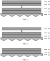
- the barrier layer can be one or more layers. When multiple binding layers are present, the number of the barrier layers can be equal to that of the binding layers ( Fig. 1 ), or one less that of the binding layers ( Fig. 2 ). In addition, both the binding layer and the barrier layer can also be one layer ( Fig. 3 ).
- the barrier layer closest to the substrate is referred to as the first barrier layer; when there are multiple barrier layers, in the direction from near to far from the substrate, the layers can be referred to as the second barrier layer, the third barrier layer, ising, the m th barrier layer.
- m is an integer of 1 - 5.
- an auxiliary agent commonly used in the art can be moderately included, for example, a conductive material, a plasticizer, a dispersion medium, a dispersant, a surfactant and various additives, and the auxiliary agent is not particularly limited, as long as it does not hinder the prevention of the migration of the first binder by the barrier layer and the binding strength thereof with the binding strength.
- the total content of the auxiliary agents can be 5 wt% or less, 4 wt% or less, 3 wt% or less, and 2 wt% or less, for example 1.95 wt%.
- a multi-component copolymer is a polymer having a function to preventing the first binder from migration, and is a polymer different from the first binder.
- the multi-component copolymer is preferably a linear multi-component copolymer. By using the linear multi-component copolymer, it is possible to ensure a good effect of preventing the migration of the first binder with a small amount.
- the linear multi-component copolymer is further preferably obtained by co-polymerizaiton using acrylonitrile, acrylic acid, or allyl ester as a monomer, and optional monomers that can be copolymerized with the above-mentioned monomers if necessary.
- the above-mentioned co-polymerization can be carried out according to a conventional method.
- the monomer can be polymerized by anions, cations, radicals, etc. in a state where the monomer is dispersed in an inert dispersion medium such as a solution, an emulsion, or a suspension, or without dispersion medium.
- a catalyst can be suitably used during the co-polymerization. Conditions such as a polymerization temperature and time can be appropriately selected according to need.
- materials obtained by commercial means can also be used as the above-mentioned multi-component copolymer.
- the principle that the multi-component copolymer can prevent the first binder from migration across the barrier layer (preventing flotation) is not certain, but it can be speculated that it is due to the differences in the properties, such as compatibility of the multi-component copolymer with the first binder, easy coating on the surface of the active material, etc., such that the first binder encounters a larger resistance force when it tries to pass the barrier layer, thereby exerting the effect of inhibiting the cross-layer migration of the first binder.
- the barrier layer is dried earlier than the binding layer in inner side, a barrier layer can be formed earlier, and the cross-layer migration of the first binder (flotation) in the binding layer closer to the substrate than the barrier layer can be effectively inhibited.
- the effect of inhibiting cross-layer migration is more significant when multiple barrier layers are provided.
- the first binder is a substance added to the slurry for forming the binding layer, to impart a binding property to the binding layer.
- the first binder is selected from at least one of styrene-butadiene rubber polymers (SBR), styrene-propadiene rubber polymers (SPR), preferably styrene-butadiene rubber polymers.
- the second binder is an optional substance added to the slurry for forming the barrier layer, to improve the binding strength with the binder layer.
- the second binder is selected from at least one of styrene-butadiene rubber polymers (SBR), styrene-propadiene rubber polymers (SPR), preferably styrene-butadiene rubber polymers.
- SBR styrene-butadiene rubber polymers
- SPR styrene-propadiene rubber polymers
- the second binder can be the same substance as the first binder, or a different substance, preferably the same one.
- the two binders in the dried electrode plate are collectively referred to as "binder", with their origin and type being not specifically distinguished.
- the electrode plate is manufactured by coating a slurry for forming a binding layer and a slurry for forming a barrier layer onto a substrate in sequence.
- the coating method is not limited, and the existing techniques and apparatus such as spray coating, dip coating, blade coating, roll coating, and extrusion coating can be used.
- Those skilled in the art can adjust the total thickness of the binding layer and the barrier layer on the substrate to a commonly controlled coating weight according to requirements, for example, more than 0.097 mg/mm 2 .
- the substrate is coated with a slurry for forming the binding layer to form a first layer film region and a slurry for forming the barrier layer to form a second layer film region, in sequence.
- a slurry for forming the binding layer to form a first layer film region and a slurry for forming the barrier layer to form a second layer film region, in sequence.
- slurries for forming both the binding layer and the barrier layer are coated repeatedly, until the respective desired numbers of layers are reached.
- the total number of layers of the binding layer and the barrier layer can be determined according to needs; a smaller total number of the layers facilitates the simplification of the apparatus, and a larger total number facilitates the inhibition of a too high concentration gradient of the binder in the layers, and thus facilitates the inhibition of the reduction of the binding strength. It should be noted that when the same slurry is continuously applied 2 times or more, the layers formed from the slurry are regarded as one layer, and when slurries of different compositions and/or concentrations are continuously applied 2 times or more, the layers formed from these slurries are regarded as different layers.
- the thickness of each layer can be determined as required, and the thickness of each layer may be appropriately set according to the required total thickness.
- the thicknesses of the various layers can be the same or different.
- the coating thickness of each layer may be expressed as a fold relative to the thickness of a basic unit thickness.
- the thickness of the basic unit thickness can be appropriately set according to the required number of layers, total thickness and apparatus conditions in the manufacturing process.
- a coating weight ratio of the total binding layers to the total barrier layers is 3 : 7 - 7 : 3, optionally 4 : 6 - 6 : 4.
- the reduction in binding strength in the electrode plate can be further inhibited.
- the coating amount can be controlled by controlling the coating thickness, etc.
- the coating thickness can be suitably controlled by those skilled in the art according to the coating method used and the characteristics of the apparatus.
- a ratio of the total weight of the first binder in all binding layers, relative to the total weight of the multi-component copolymer and the optional second binder in all barrier layers is 0.5 : 2.6 - 3.0 : 0.1, optionally 1.8 : 1.3.
- the reduction in binding strength in the electrode plate can be further inhibited.
- the substrate is placed into an oven for drying. During the drying process, volatile substances in the slurry, such as the dispersion medium, are removed to form an electrode plate with a multilayer structure on the surface of the substrate.
- the electrode plate can be dried in a batch process using a box-type oven, or can be dried in a continuous process using a tunnel-type oven.
- a tunnel-type oven it is preferred to use a tunnel-type oven to dry the electrode plate in a continuous manner.
- the oven can be heated by means of a heating method using hot air, or a heating method using infrared, or other known heating methods. Further, it may be a combination of the above heating methods.
- the temperature of the oven is appropriately set according to the substances used, and can be adjusted by those skilled in the art according to the heating method for the oven and the drying condition of the electrode plate.
- the lower limit of the temperature can be 70°C or more, 80°C or more, 90°C or more, 100°C or more, 110°C or more, 120°C or more, and 130°C or more, for example 140°C.
- the upper limit of the temperature of the oven is no more than the decomposition temperatures of the binder, substrate and various auxiliary agents used. A too high temperature easily results in the material aging, and a too low temperature can not achieve the high-speed production.
- the drying time is appropriately set according to the materials used and the temperature of the oven, and the upper limit can be 600 sec or less, 500 sec or less, 400 sec or less, 300 sec or less, 240 sec or less, 180 sec or less, 120 or less, and 60 sec or less.
- the lower limit of the drying time is 1 sec or more, 2 sec or more, 3 sec or more, 5 sec or more, 7 sec or more, and 10 sec or more. A too short time can not achieve the sufficient drying of the electrode plate, and a too long time easily results in the material aging and can not achieve the high-speed production.
- the present invention can also be achieved in a production line that does not use a high-speed coating, but preferably in a production line that uses high-speed coating.
- a secondary battery is provided.
- a secondary battery comprises a positive electrode plate, a negative electrode plate, an electrolyte and a separator.
- active ions are intercalated and de-intercalated back and forth between a positive electrode plate and a negative electrode plate.
- the electrolyte is between the positive electrode plate and the negative electrode plate and functions for conducting ions.
- the separator is provided between the positive electrode plate and the negative electrode plate, and mainly prevents the positive and negative electrodes from short-circuiting and enables ions to pass through.
- the electrolyte is between the positive electrode plate and the negative electrode plate and functions for conducting ions.
- the type of the electrolyte is not specifically limited in the present application, and can be selected according to actual requirements.
- the electrolyte may be in a liquid state, a gel state or an all-solid state.
- the electrolyte is an electrolyte solution.
- the electrolyte solution includes an electrolyte salt and a solvent.
- the electrolyte salt may be selected from at least one of lithium hexafluorophosphate, lithium tetrafluoroborate, lithium perchlorate, lithium hexafluoroarsenate, lithium bisfluorosulfonimide, lithium bistrifluoromethanesulfonimide, lithium trifluoromethanesulfonate, lithium difluorophosphate, lithium difluorooxalate borate, lithium dioxalate borate, lithium difluorodioxalate phosphate and lithium tetrafluorooxalate phosphate.
- the solvent may be selected from at least one of ethylene carbonate, propylene carbonate, ethyl methyl carbonate, diethyl carbonate, dimethyl carbonate, dipropyl carbonate, methyl propyl carbonate, ethyl propyl carbonate, butylene carbonate, fluoroethylene carbonate, methyl formate, methyl acetate, ethyl acetate, propyl acetate, methyl propionate, ethyl propionate, propyl propionate, methyl butyrate, ethyl butyrate, 1,4-butyrolactone, sulfolane, dimethyl sulfone, ethyl methyl sulfone, and diethyl sulfone.
- the electrolytic solution may optionally include an additive.
- the additive may include a negative electrode film-forming additive and a positive electrode film-forming additive, and may further include an additive that can improve certain performances of the battery, such as an additive that improves the overcharge performance of the battery, or an additive that improves the high temperature or low-temperature performance of the battery.
- the secondary battery further comprises a separator.
- the type of the separator is not particularly limited in the present application, and any well known porous-structure separator with good chemical stability and mechanical stability may be selected.
- the material of the separator may be selected from at least one of glass fibers, non-woven fabrics, polyethylene, polypropylene and polyvinylidene fluoride.
- the separator may be a single-layer film or a multi-layer composite film, and is not limited particularly. When the separator is a multi-layer composite film, the materials in the respective layers may be same or different, which is not limited particularly.
- the positive electrode plate, the negative electrode plate and the separator can be made into the electrode assembly by a winding process or a stacking process.
- the secondary battery may comprise an outer package.
- the outer package can be used to encapsulate the above-mentioned electrode assembly and electrolyte.
- the outer package of the secondary battery may be a hard shell, such as a hard plastic shell, an aluminum shell, or a steel shell.
- the outer package of the secondary battery may also be a soft bag, such as a pouch-type soft bag.
- the material of the soft bag may be plastics, and the examples of plastics may include polypropylene, polybutylene terephthalate, and polybutylene succinate, etc.
- the shape of the secondary battery is not particularly limited in the present application, and may be cylindrical, square or of any other shape.
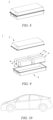
- Fig. 5 shows a secondary battery 5 with a square structure as an example.
- an outer package may comprise a housing 51 and a cover plate 53.
- the housing 51 may comprise a bottom plate and side plates connected to the bottom plate, and the bottom plate and the side plates enclose to form an accommodating cavity.
- the housing 51 has an opening in communication with the accommodating cavity, and the cover plate 53 can cover the opening to close the accommodating cavity.
- the positive electrode plate, the negative electrode plate and the separator can be subjected to a winding process or a laminating process to form an electrode assembly 52.
- the electrode assembly 52 is encapsulated in the accommodating cavity.
- the electrolyte is infiltrated into the electrode assembly 52.
- the number of the electrode assemblies 52 contained in the secondary battery 5 may be one or more, and can be selected by those skilled in the art according to actual requirements.
- the secondary battery can be assembled into a battery module, and the number of the secondary batteries contained in the battery module may be one or more, and the specific number can be selected by those skilled in the art according to the application and capacity of the battery module.
- Fig. 7 shows a battery module 4 as an example.
- a plurality of secondary batteries 5 may be arranged in sequence in the length direction of the battery module 4.
- the secondary batteries may also be arranged in any other manner.
- the plurality of secondary batteries 5 may be fixed by fasteners.
- the battery module 4 may also comprise a housing with an accommodating space, and a plurality of secondary batteries 5 are accommodated in the accommodating space.
- the above battery module may also be assembled into a battery pack, the number of the battery modules contained in the battery pack may be one or more, and the specific number can be selected by those skilled in the art according to the application and capacity of the battery pack.
- the battery pack 1 may comprise a battery box and a plurality of battery modules 4 provided in the battery box.
- the battery box comprises an upper box body 2 and a lower box body 3, wherein the upper box body 2 can cover the lower box body 3 to form a closed space for accommodating the battery modules 4.
- a plurality of battery modules 4 may be arranged in the battery box in any manner.
- the present application further provides a power consuming device.
- the power consuming device comprises at least one of the secondary battery, battery module, or battery pack provided by the present application.
- the secondary battery, battery module or battery pack can be used as a power source of the power consuming device or as an energy storage unit of the power consuming device.
- the power consuming device may include a mobile device (e.g., a mobile phone, a laptop computer, etc.), an electric vehicle (e.g., a pure electric vehicle, a hybrid electric vehicle, a plug-in hybrid electric vehicle, an electric bicycle, an electric scooter, an electric golf cart, an electric truck), an electric train, ship, and satellite, an energy storage system, and the like, but is not limited thereto.
- the secondary battery, battery module or battery pack can be selected according to the usage requirements thereof.
- Fig. 10 shows a power consuming device as an example.
- the power consuming device may be a pure electric vehicle, a hybrid electric vehicle, a plug-in hybrid electric vehicle or the like.
- a battery pack or a battery module may be used.
- the electrical apparatus may be a mobile phone, a tablet computer, a laptop computer, etc.
- the electrical apparatus is generally required to be thin and light, and may use the secondary battery as a power supply.
- a commercially available copper substrate is coated with a slurry comprising a first binder for forming a binding layer (abbreviated as "binding layer slurry”) and a slurry comprising a multi-component copolymer and an optional second binder for forming a barrier layer (abbreviated as "barrier layer slurry”) in sequence, by the methods and conditions as shown in the tables below.
- binding layer slurry a slurry comprising a first binder for forming a binding layer
- barrier layer slurry a slurry comprising a multi-component copolymer and an optional second binder for forming a barrier layer
- binding layer slurry a slurry for forming a binding layer
- barrier layer slurry a slurry for forming a barrier layer
- a wight ratio of graphite : the first binder : an auxiliary agent is 97.55 : 0.5 : 1.95 - 94.85 : 3.2 : 1.95; and in the barrier layer slurry, a wight ratio of graphite : (the multi-component copolymer and an optional second binder) : an auxiliary agent is 97.55 : 0.5 : 1.95 - 94.85 : 3.2 : 1.95.
- Each slurry also contains a dispersion medium, and the viscosity of each slurry is adjusted to a viscosity suitable for spray coating by using the dispersion medium.
- a binding layer slurry is spray-coated onto the substrate to form a first binding layer, and then a barrier layer slurry is coated onto the first binding layer to form a first barrier layer.
- a binding layer slurry containing a required amount of a first binder and a barrier layer slurry containing a required amount of a multi-component copolymer and a second binder are alternately spray-coated, until the specified number of layers is reached.
- the fold of the thickness of each layer relative to the basic unit thickness is shown in the table.
- the basic unit thickness may vary among various examples and comparative examples. Also, it can be considered that the thickness ratio between the layers in the electrode plate after drying is approximately equal to the thickness ratio of the coating amount of each layer.
- the substrate and the slurry are dried in a 60 m tunnel-type oven at a conveying speed of 90 m/min with a baking temperature of 110-140°C.
- a multilayer electrode plate is thus formed.
- a coating weight ratio of the binding layer to the barrier layer is as shown in the table.
- the performance of the electrode plate is evaluated in the following manner.
- the electrode plate After having been dried, the electrode plate is cooled to room temperature, the total thickness of the binding layer and the barrier layer is divided into three equal portions in the thickness direction, and the thickness of the one third portion closest to the surface is collected as an upper layer sample; and the thickness of the one third portion closest to the substrate is collected as an lower layer sample.
- About 50 mg of the powder of the upper layer sample or the lower layer sample is accurately weighed and placed into a test dish, and the thermal weight loss of the sample is measured by a TG measuring instrument manufactured by the NETZSCH company.
- an obvious weight loss ( w) observed around 400°C in the heating curve is used as the content of the binder and the multi-component copolymer, and the weight of the sample at the beginning of the heating curve is used as a reference to calculate the content of the binder and the multi-component copolymer.
- Table 2 shows the ratio of the binder content contained in the upper and lower layers of examples and comparative examples, and the percentage relative to comparative example 1.
- a special double-sided adhesive tape with a size of 20 mm width ⁇ 90 - 150 mm length is adhered onto a steel plate, and an electrode plate with a size of 30 mm width ⁇ 160 mm length is cut and adhered on the double-sided adhesive tape, and then rolled three times in the same direction with a press roller.
- the steel plate is fixed with a lower clamping head of a tensile machine, and the electrode plate is fixed with an upper clamping head, and then a pre-stretching (5-10 mm) is carried out at a tensile speed of 50 mm/min by the 180° peeling method.
- the state after the pre-stretching is referred to as "zero point", and then the main stretching is started, and the stretching is stopped after the main stretching is 45-50 mm.
- the evaluation results are also shown in Table 2.
- the electrode plate of the present invention can inhibit the floating of the binder, and improve the binding strength between the substrate and the binding layer in the electrode plate.
- examples 1 to 3 with comparative examples 1 to 3, it can be seen that under the same coating conditions, the electrode plate with a barrier layer of the present invention can inhibit the floating of the binder, and improves the binding strength between the substrate and the binder layer.
- the tendency of the binder to float is also sufficiently inhibited, and the binding strength is improved.
Landscapes
- Chemical & Material Sciences (AREA)
- Chemical Kinetics & Catalysis (AREA)
- Electrochemistry (AREA)
- General Chemical & Material Sciences (AREA)
- Engineering & Computer Science (AREA)
- Manufacturing & Machinery (AREA)
- Materials Engineering (AREA)
- Composite Materials (AREA)
- Battery Electrode And Active Subsutance (AREA)
Abstract
Description
- The present application relates to the fields of batteries, and in particular to a multilayer electrode plate and a negative electrode using same, a battery and a power consuming device.
- Achieving energy conservation and emission reduction is the key to the sustainable development of the automotive industry. Electric vehicles have become an important part of the sustainable development of the automotive industry due to their advantages in energy conservation and being environmentally friendly. For the electric vehicles, the secondary battery technology is an important factor to their development.
- In the secondary batteries, a multilayer electrode plate at least comprising a substrate, an active material layer containing a binder in sequence is widely used. In the manufacture of a multilayer electrode plate, the binder comprised in the active material layer may migrate towards the surface of the electrode plate, resulting in reduced binding strength in the electrode plate. In the prior art (
CN 113351450 A ), in order to solve such problems, it is proposed that slurries with different binder contents are coated on the substrate in multiple portions at a relatively low coating speed, to form a binding layer. However, at a high coating speed, these problems are not fully solved. - In view of the above problems, the present application provides a multilayer electrode plate, which solves the problem that the binder migrates away from the substrate under high-speed coating, resulting in a decrease in the binding strength of the electrode plate.
- In one aspect of the present application, provided is a multilayer electrode plate, wherein the multilayer electrode plate comprises a substrate, at least one binding layer and at least one barrier layer laminated in sequence on the substrate, wherein the binding layer and the barrier layer are distributed alternately in the thickness direction of the multilayer electrode plate; the binding layer comprises a first binder; and the barrier layer comprises a multi-component copolymer different from the first binder and an optional second binder, identical to or different from the first binder.
- In the technical solution of the embodiment in the present application, the binding layer differs from the barrier layer in that the barrier layer comprises a multi-component copolymer different from the first binder, by the alternate distribution of the binding layer and the barrier layer in the thickness direction of the electrode plate, the multi-component copolymer can prevent the first binder from migrating across the barrier layer towards the direction away from the substrate; thus, even though a high-speed coating manufacturing method is used to prepare the electrode plate, the first binder can also be inhibited from getting away from the substrate, improving the binding strength between the binding layer and the substrate, and thus inhibiting the reduction in binding strength in the electrode plate. In some embodiments, the multi-component copolymer is a linear multi-component copolymer which is formed by co-polymerization with acrylonitrile, acrylic acid, allyl ester, etc., as a monomer. Thus, the migration of the first binder across the barrier layer can be well restricted.
- In some embodiments, the multilayer electrode plate comprises one said binding layer and one said barrier layer, with one said binding layer and one said barrier layer being provided on the substrate in sequence. By providing one binding layer and one barrier layer, and providing the binding layer and the barrier layer on the substrate in sequence, the first binder is inhibited from migrating away from the substrate, and thus inhibiting the reduction in binding strength in the electrode plate, while simplifying the manufacturing process for the electrode plate.
- In some embodiments, the first binder and the second binder are selected from at least one of styrene-butadiene rubber polymers and styrene-propadiene rubber polymers. Thus, sufficient binding strength with the substrate can be ensured.
- In some embodiments, in the binding layer, the first binder has a content of 0.5 - 3.2 wt%, preferably 1.3 - 1.8 wt%.
- In some embodiments, in the barrier layer, the multi-component copolymer has a content of 0.5 - 3.2 wt%, preferably 1.3 - 2.6 wt%; when the optional second binder is comprised, the multi-component copolymer and the optional second binder have a total content of 0.5 - 3.2 wt%, preferably 1.3 - 2.6 wt%. Thus, the reduction in binding strength in the electrode plate can be further inhibited.
- In some embodiments, a ratio of addition amount (%) of the first binder in the binding layer, relative to the total addition amount (%) of the multi-component copolymer and the optional second binder in the barrier layer, is 0.5 : 2.6 - 3.0 : 0.1, optionally1.8 : 1.3. Thus, the reduction in binding strength in the electrode plate can be further inhibited.
- In some embodiments, the coating weight ratio of the binding layer to the barrier layer is 3 : 7 - 7: 3, optionally, 4 : 6 - 6 : 4. Thus, the reduction in binding strength in the electrode plate can be further inhibited.
- In some embodiments, in the barrier layer, the addition amount ratio of the multi-component copolymer to the second binder is 1 or more, optionally 2.5 or more. Thus, the migration of the first binder across the barrier layer can be further restricted.
- In another aspect of the present invention, provided is a negative electrode, comprising a multilayer electrode plate in the above embodiments.
- In another aspect of the present invention, provided is a secondary battery, comprising a negative electrode in the above embodiments.
- In another aspect of the present invention, provided is a battery module, comprising a secondary battery described above.
- In another aspect of the present invention, provided is a battery pack, comprising a battery module described above.
- In another aspect of the present invention, provided is a power consuming device, comprising a secondary battery described above, a battery module described above or a battery pack described above. The secondary battery, the battery module, and the battery pack are all used for providing electrical energy.
- The aforementioned description is only an overview of the technical solutions of the present application. In order to more clearly understand the technical means of the present application to implement same according to the contents of the specification, and in order to make the aforementioned and other objects, features and advantages of the present application more obvious and understandable, specific embodiments of the present application are exemplarily described below.
- Various other advantages and benefits will become apparent to those of ordinary skill in the art upon reading the following detailed description of preferred embodiments. The drawings are merely for the purpose of illustrating the preferred embodiments and are not to be construed as limiting the present application. Moreover, like components are denoted by like reference numerals throughout the drawings. In the drawings:
-
Fig. 1 is a schematic structural diagram of a multilayer electrode plate according to some embodiments of the present application; -
Fig. 2 is a schematic structural diagram of a multilayer electrode plate according to some embodiments of the present application; -
Fig. 3 is a schematic structural diagram of a multilayer electrode plate according to some embodiments of the present application; -
Fig. 4 is a graph schematically illustrating the determination method for the binder and the multi-component copolymer in the binding layer and barrier layer of the electrode plate; -
Fig. 5 is a schematic diagram of a secondary battery according to some embodiments of the present application; -
Fig. 6 is an exploded schematic diagram of a secondary battery according to some embodiments of the present application; -
Fig. 7 is a schematic diagram of a battery module according to some embodiments of the present application; -
Fig. 8 is a schematic diagram of a battery pack according to some embodiments of the present application; -
Fig. 9 is an exploded schematic diagram of a battery pack according to some embodiments of the present application; and -
Fig. 10 is a power consuming device according to some embodiments of the present application. - 1 battery pack; 2 upper case body; 3 lower case body; 4 battery module; 5 secondary battery; 11 first layer film region: binding layer; 12 second layer film region: barrier layer; 13 substrate; 14 the nth layer film region: binding layer; 15 the mth layer film region: barrier layer;
- Embodiments of the technical solutions of the present application will be described in more detail below. The following embodiments are merely intended to more clearly illustrate the technical solutions of the present application, so they merely serve as examples, but are not intended to limit the scope of protection of the present application.
- Unless otherwise defined, all technical and scientific terms used herein have the same meanings as those commonly understood by those skilled in the art to which the present application belongs. The terms used herein are merely for the purpose of describing specific embodiments, but are not intended to limit the present application. The terms "comprising" and "having" and any variations thereof in the description and the claims of the present application as well as the brief description of the drawings described above are intended to cover non-exclusive inclusion.
- In the description of the embodiments of the present application, the technical terms "first", "second", etc. are merely used for distinguishing different objects, and are not to be construed as indicating or implying relative importance or implicitly indicating the number, particular order or primary-secondary relationship of the technical features modified thereby. In the description of the embodiments of the present application, the phrase "a plurality of" means two or more, unless otherwise explicitly and specifically defined.
- The phrase "embodiment" mentioned herein means that the specific features, structures, or characteristics described in conjunction with the embodiment may be encompassed in at least one embodiment of the present application. The phrase at various locations in the description does not necessarily refer to the same embodiment, or an independent or alternative embodiment exclusive of another embodiment. Those skilled in the art understand explicitly or implicitly that the embodiment described herein may be combined with another embodiment.
- In the description of the embodiments of the present application, the term "and/or" is merely intended to describe the associated relationship of associated objects, representing that three relationships can exist, for example, A and/or B can include: the three instances of A alone, A and B simultaneously, and B alone. In addition, the character "/" herein generally indicates an "or" relationship between the associated objects.
- In the description of the embodiments of the present application, the term "a plurality of" means two or more (including two), similarly the term "a plurality of groups" means two or more groups (including two groups), and the term "a plurality of pieces" means two or more pieces (including two pieces).
- In the description of the embodiments of the present application, the orientation or position relationship indicated by the technical terms "central", "longitudinal", "transverse", "length", "width", "thickness", "upper", "lower", "front"; "rear", "left", "right", "vertical", "horizontal", "top", "bottom", "inner", "outer", "clockwise", "counterclockwise", "axial", "radial", "circumferential", etc. are based on the orientation or position relationship shown in the drawings and are merely intended to facilitate and simplify the description of the embodiments of the present application, rather than indicating or implying that the device or element considered must have a particular orientation or be constructed and operated in a particular orientation, and therefore not to be construed as limiting the embodiments of the present application.
- At present, from the perspective of the development of the market situation, the traction batteries are used more and more widely. The traction batteries are not only used in energy storage power systems such as hydroelectric power plants, thermal power plants, wind power plants and solar power plants, but also widely used in many fields, for example, in electric transportation means such as electric bicycles, electric motorcycles and electric vehicles. With the continuous expansion of the application field of traction batteries, the market demand for the traction batteries is also expanding.
- The present inventor has noticed that the life of the electrode plate used in the battery will significantly affect that of the battery, so in order to obtain a high battery life, it is necessary to use a high-quality electrode plate. However, with the rapid growth of battery demand, it is urgent to improve the production efficiency of electrode plates.
- In order to improve the production efficiency of the electrode plate, accelerating the coating speed of the materials forming the various layers in the electrode plate has a significant effect on the increase of speed and efficiency. However, the present inventors have found that as the coating speed increases, it becomes more difficult to inhibit the migration of the binder. Furthermore, there arises the problem of the reduction in binding strength.
- In the process of preparing the electrode plate, a slurry in which a binder or the like is dispersed in a dispersion medium is usually coated on the substrate, and then dried to remove the dispersion medium to form a binding layer. In the dried electrode plate, the content of the binders in the "surface layer" of the binding layer potion and the "bottom layer" close to the substrate will be different due to migration. The content difference will be presented in the form of a concentration gradient.
- As the reason for this concentration difference, it is generally believed that during the drying process, due to the effects of surface tension, capillary phenomenon, concentration difference, etc., a power by which the binder migrates (sometimes also referred to as "float") away from the substrate in the layer will spontaneously produces. The present inventors have found that this power is particularly significant during high-speed coating, and has a larger impact on the quality of the finished electrode plate product. The reason for this is not certain, but it is presumed that it is necessary to increase the temperature and air speed in the oven in order to satisfy the drying conditions during high-speed coating. At this time, the surface of the electrode plate becomes dry quickly, the tension difference between the inside and outside of the electrode plate increases, and the internal dispersion medium quickly rises to the surface, and the binder will migrate to the surface along with the molecules of the dispersion medium, which will present a binder migration increase.
- In order to alleviate the problem of reduced binding strength, the present inventors have found that by providing a barrier layer comprising a multi-component copolymer on a binding layer and/or between multiple binding layers, the migration of the binder in the binding layer across the barrier layer can be prevented. Thus, the binder content in the binding layer near the substrate can be effectively reduced, and then the reduction in binding strength can be inhibited.
- Therefore, in a first aspect, the present invention provides an electrode plate which improves the binding strength of the binding layer with a component, such as a substrate. The specific contents are as follows.
- The electrode plate of the present invention is an electrode plate for preparing a positive electrode or a negative electrode for a battery. The electrode plate comprises a substrate, a binding layer, a barrier layer, etc.
- The electrode plate of the present invention comprises a substrate, and the substrate is a current collector, which can be a current collector composed entirely of a conductive material or a composite current collector composed of a non-conductive material coated with a conductive material. The type of the substrate is not particularly limited in the present application, and any known substrate can be selected.
- In some embodiments, the positive electrode current collector can be a metal foil or a composite current collector. For example, as a metal foil, an aluminum foil can be used. The composite current collector may comprise a polymer material substrate and a metal layer formed on at least one surface of the polymer material substrate. The composite current collector can be formed by forming a metal material (aluminum, an aluminum alloy, nickel, a nickel alloy, titanium, a titanium alloy, silver and a silver alloy, etc.) on a polymer material substrate (such as polypropylene (PP), polyethylene terephthalate (PET), polybutylene terephthalate (PBT), polystyrene (PS), polyethylene (PE), etc.).
- In some embodiments, the negative electrode current collector can be a metal foil or a composite current collector. For example, as a metal foil, a copper foil can be used. The composite current collector may comprise a polymer material substrate and a metal layer formed on at least one surface of the polymer material substrate. The composite current collector can be formed by forming a metal material (copper, a copper alloy, nickel, a nickel alloy, titanium, a titanium alloy, silver and a silver alloy, etc.) on a polymer material substrate (e.g., polypropylene (PP), polyethylene terephthalate (PET), polybutylene terephthalate (PBT), polystyrene (PS), polyethylene (PE), etc.).
- The electrode plate of the present invention includes an active substance, and the active substance directly or indirectly covers the substrate by the dispersion in the binding layer or barrier layer. In the present application, the type of the active substance is not particularly limited, and any known active substances can be included, such as carbon based-materials, sulfur-based materials, silicon-based materials, etc. It should be noted that the active material is a material participating in the current generating reaction in the positive electrode and the negative electrode of the battery.
- In some embodiments, the positive active material may be a positive active material known in the art for batteries. As an example, the positive electrode active material may include at least one of the following materials: lithium-containing phosphates of an olivine structure, lithium transition metal oxides and their respective modified compounds. However, the present application is not limited to these materials, and other conventional materials that can be used as positive electrode active materials for batteries may also be used. These positive electrode active materials may be used alone or in combination of two or more. Herein, examples of lithium transition metal oxides may include, but are not limited to, at least one of lithium cobalt oxide (e.g. LiCoO2), lithium nickel oxide (e.g. LiNiO2), lithium manganese oxide (e.g. LiMnO2, LiMn2O4), lithium nickel cobalt oxide, lithium manganese cobalt oxide, lithium nickel manganese oxide, lithium nickel cobalt manganese oxide (e.g. LiNi1/3Co1/3Mn1/3O2 (also referred to as NCM333), LiNi0.5Co0.2Mn0.3O2 (also referred to as NCM523), LiNi0.5Co0.25Mn0.25O2 (also referred to as NCM211), LiNi0.6Co0.2Mn0.2O2 (also referred to as NCM622), LiNi0.8Co0.1Mn0.1O2 (also referred to as NCM811)), lithium nickel cobalt aluminum oxide (e.g. LiNi0.85Co0.15Al0.05O2), and modified compounds thereof, and the like. Examples of lithium-containing phosphates of olivine structure may include, but are not limited to, at least one of lithium iron phosphate (e.g. LiFePO4 (also referred to as LFP)), lithium iron phosphate and carbon composites, lithium manganese phosphate (e.g. LiMnPO4), lithium manganese phosphate and carbon composites, lithium iron manganese phosphate, and lithium iron manganese phosphate and carbon composites.
- In some embodiments, the negative electrode active material can be a negative electrode active material known in the art for batteries. As an example, the negative electrode active material may include at least one of the following materials: synthetic graphite, natural graphite, soft carbon, hard carbon, a silicon-based material, a tin-based material and lithium titanate, etc. The silicon-based material may be selected from at least one of elemental silicon, silicon oxides, silicon carbon composites, silicon nitrogen composites and silicon alloys. The tin-based material may be selected from at least one of elemental tin, tin oxides, and tin alloys. However, the present application is not limited to these materials, and other conventional materials that can be used as negative electrode active materials for batteries can also be used. These negative electrode active materials may be used alone or in combination of two or more.
- A binding layer is a layer comprising a first binder and an active substance, for binding the substrate with the active substance together. In the binding layer, the first binder has a content of 0.5 - 3.2 wt%, preferably 1.3 - 1.8 wt%.
- In the binding layer, from the viewpoint of battery capacity, the higher the active material content, the better, for example 90 wt% or more, but from the viewpoint of binding strength, it is necessary to add a binder, etc., so the active substance has a content of 99 wt% or less, for example, 97.55 - 94.85 wt%.
- In the binding layer, the binding layer closest to the substrate is referred to as the first binding layer; when there are multiple binding layers, in the direction from near to far from the substrate, the layers can be referred to as the second binding layer, the third binding layer, ......, the nth binding layer. In such a case, n is preferably an integer of 1 - 5.
- When there are multiple binding layers, the first binder contents in the various layers can be the same or different. The same first binder content in the various layers facilitates the simplification of the production line; when the first binder contents in the various layers are different, it is preferred that the first binder content in the binding layer close to the substrate is higher, and the first binder content in each layer becomes a gradient decrease as it moves away from the substrate; in such a way, even though the first binder migrates cross the layer, a sufficient binding strength between the binding layer and the substrate can be ensured.
- In the binding layer, an auxiliary agent commonly used in the art can be moderately included, for example, a conductive material, a plasticizer, a dispersion medium, a dispersant, a surfactant and various additives, and the auxiliary agent is not particularly limited, as long as it does not affects the binding strength of the binding layer with the substrate and/or the active substance. The total content of the auxiliary agents can be 5 wt% or less, 4 wt% or less, 3 wt% or less, and 2 wt% or less, for example 1.95 wt%.
- The barrier layer comprises a multi-component copolymer different from the first binder in the binding layer and is a layer preventing the first binder from migrating across the layer. By providing the barrier layer on the binding layer and/or between multiple binding layers, the first binder in the binding layer can be prevented from migrating across the barrier layer. In the barrier layer, a second binder, identical to or different from the first binder, can be optionally included. By including a second binder, the cohesive force of the electrode plate can be improved, the roll sticking of the electrode plate during cold pressing is avoided, and the binding strength between them can be improved, facilitating the whole binding strength of the electrode plate.
- In the barrier layer, the multi-component copolymer has a content of 0.5 - 3.2 wt%, preferably 1.3 - 2.6 wt%; when the optional second binder is comprised, the multi-component copolymer and the optional second binder have a total content of 0.5 - 3.2 wt%, preferably 1.3 - 2.6 wt%. When the multi-component copolymer content is too high, there will be problems, such as a poor electrode plate cohesive force, and roll sticking during cold pressing; when the content is too low, it is difficult to achieve the effect of preventing the first binder from migration. When the multi-component copolymer and the optional second binder have a too high total content, the amount of the active substance will be reduced, which is not conducive to the improvement of the battery capacity; when the total content is too low, the multi-component copolymer content is too low, and it is difficult to achieve the effect of preventing the first binder from migration.
- In the barrier layer, a weight ratio of the multi-component copolymer to the second binder can be 1 or more, preferably 2.5 or more. Thus, the migration of the first binder across the barrier layer can be further restricted.
- When multiple barrier layers are present, the contents of the multi-component copolymer and second binder can be the same or different in the various layers. The same content of the multi-component copolymer and second binder in the various layers facilitates the simplification of the production line.
- The barrier layer can also comprise an active substance, and when the active substance is comprised, the active substance can be the same or different from that in the binding layer, but for the production efficiency, it may be the same as that in the binding layer. From the viewpoint of battery capacity, the active substance has a content of 90 wt% or more, and from the viewpoint of binding strength, the active substance has a content of 99 wt% or less, for example 97.55 - 94.85 wt%.
- The barrier layer can be one or more layers. When multiple binding layers are present, the number of the barrier layers can be equal to that of the binding layers (
Fig. 1 ), or one less that of the binding layers (Fig. 2 ). In addition, both the binding layer and the barrier layer can also be one layer (Fig. 3 ). - In the barrier layer, the barrier layer closest to the substrate is referred to as the first barrier layer; when there are multiple barrier layers, in the direction from near to far from the substrate, the layers can be referred to as the second barrier layer, the third barrier layer, ......, the mth barrier layer. In such a case, m is an integer of 1 - 5.
- In the barrier layer, an auxiliary agent commonly used in the art can be moderately included, for example, a conductive material, a plasticizer, a dispersion medium, a dispersant, a surfactant and various additives, and the auxiliary agent is not particularly limited, as long as it does not hinder the prevention of the migration of the first binder by the barrier layer and the binding strength thereof with the binding strength. The total content of the auxiliary agents can be 5 wt% or less, 4 wt% or less, 3 wt% or less, and 2 wt% or less, for example 1.95 wt%.
- A multi-component copolymer is a polymer having a function to preventing the first binder from migration, and is a polymer different from the first binder. The multi-component copolymer is preferably a linear multi-component copolymer. By using the linear multi-component copolymer, it is possible to ensure a good effect of preventing the migration of the first binder with a small amount. The linear multi-component copolymer is further preferably obtained by co-polymerizaiton using acrylonitrile, acrylic acid, or allyl ester as a monomer, and optional monomers that can be copolymerized with the above-mentioned monomers if necessary.
- The above-mentioned co-polymerization can be carried out according to a conventional method. For example, the monomer can be polymerized by anions, cations, radicals, etc. in a state where the monomer is dispersed in an inert dispersion medium such as a solution, an emulsion, or a suspension, or without dispersion medium. A catalyst can be suitably used during the co-polymerization. Conditions such as a polymerization temperature and time can be appropriately selected according to need. In addition, materials obtained by commercial means can also be used as the above-mentioned multi-component copolymer.
- The principle that the multi-component copolymer can prevent the first binder from migration across the barrier layer (preventing flotation) is not certain, but it can be speculated that it is due to the differences in the properties, such as compatibility of the multi-component copolymer with the first binder, easy coating on the surface of the active material, etc., such that the first binder encounters a larger resistance force when it tries to pass the barrier layer, thereby exerting the effect of inhibiting the cross-layer migration of the first binder. In particular, since the barrier layer is dried earlier than the binding layer in inner side, a barrier layer can be formed earlier, and the cross-layer migration of the first binder (flotation) in the binding layer closer to the substrate than the barrier layer can be effectively inhibited. The effect of inhibiting cross-layer migration is more significant when multiple barrier layers are provided.
- The first binder is a substance added to the slurry for forming the binding layer, to impart a binding property to the binding layer. The first binder is selected from at least one of styrene-butadiene rubber polymers (SBR), styrene-propadiene rubber polymers (SPR), preferably styrene-butadiene rubber polymers.
- The second binder is an optional substance added to the slurry for forming the barrier layer, to improve the binding strength with the binder layer. The second binder is selected from at least one of styrene-butadiene rubber polymers (SBR), styrene-propadiene rubber polymers (SPR), preferably styrene-butadiene rubber polymers. When the barrier layer comprises a second binder, in view of the increase of the binding strength with the binding layer, the second binder can be the same substance as the first binder, or a different substance, preferably the same one. In the dried electrode plate, since the first binder in the binding layer and the second binder in the barrier layer both have a certain degree of migration in the direction towards each other, herebelow, the two binders in the dried electrode plate are collectively referred to as "binder", with their origin and type being not specifically distinguished.
- In the present invention, the electrode plate is manufactured by coating a slurry for forming a binding layer and a slurry for forming a barrier layer onto a substrate in sequence. The coating method is not limited, and the existing techniques and apparatus such as spray coating, dip coating, blade coating, roll coating, and extrusion coating can be used. Those skilled in the art can adjust the total thickness of the binding layer and the barrier layer on the substrate to a commonly controlled coating weight according to requirements, for example, more than 0.097 mg/mm2.
- During the coating, the substrate is coated with a slurry for forming the binding layer to form a first layer film region and a slurry for forming the barrier layer to form a second layer film region, in sequence. In the case of forming multiple binding layers and multiple barrier layers, slurries for forming both the binding layer and the barrier layer are coated repeatedly, until the respective desired numbers of layers are reached.
- During the coating, the total number of layers of the binding layer and the barrier layer can be determined according to needs; a smaller total number of the layers facilitates the simplification of the apparatus, and a larger total number facilitates the inhibition of a too high concentration gradient of the binder in the layers, and thus facilitates the inhibition of the reduction of the binding strength. It should be noted that when the same slurry is continuously applied 2 times or more, the layers formed from the slurry are regarded as one layer, and when slurries of different compositions and/or concentrations are continuously applied 2 times or more, the layers formed from these slurries are regarded as different layers.
- During the coating, the thickness of each layer can be determined as required, and the thickness of each layer may be appropriately set according to the required total thickness. The thicknesses of the various layers can be the same or different. Also, the coating thickness of each layer may be expressed as a fold relative to the thickness of a basic unit thickness. The thickness of the basic unit thickness can be appropriately set according to the required number of layers, total thickness and apparatus conditions in the manufacturing process. During the coating, a coating weight ratio of the total binding layers to the total barrier layers is 3 : 7 - 7 : 3, optionally 4 : 6 - 6 : 4. Thus, the reduction in binding strength in the electrode plate can be further inhibited. It should be noted that, in the case where there is no much difference in the density of the slurries for manufacturing the binding layer and the barrier layer, the coating amount can be controlled by controlling the coating thickness, etc. The coating thickness can be suitably controlled by those skilled in the art according to the coating method used and the characteristics of the apparatus.
- During the coating, a ratio of the total weight of the first binder in all binding layers, relative to the total weight of the multi-component copolymer and the optional second binder in all barrier layers is 0.5 : 2.6 - 3.0 : 0.1, optionally 1.8 : 1.3. Thus, the reduction in binding strength in the electrode plate can be further inhibited.
- In the present invention, after each slurry is coated on the substrate, the substrate is placed into an oven for drying. During the drying process, volatile substances in the slurry, such as the dispersion medium, are removed to form an electrode plate with a multilayer structure on the surface of the substrate.
- In the drying process, the electrode plate can be dried in a batch process using a box-type oven, or can be dried in a continuous process using a tunnel-type oven. However, from the viewpoint of production efficiency, it is preferred to use a tunnel-type oven to dry the electrode plate in a continuous manner.
- The oven can be heated by means of a heating method using hot air, or a heating method using infrared, or other known heating methods. Further, it may be a combination of the above heating methods.
- The temperature of the oven is appropriately set according to the substances used, and can be adjusted by those skilled in the art according to the heating method for the oven and the drying condition of the electrode plate. The lower limit of the temperature can be 70°C or more, 80°C or more, 90°C or more, 100°C or more, 110°C or more, 120°C or more, and 130°C or more, for example 140°C. The upper limit of the temperature of the oven is no more than the decomposition temperatures of the binder, substrate and various auxiliary agents used. A too high temperature easily results in the material aging, and a too low temperature can not achieve the high-speed production.
- The drying time is appropriately set according to the materials used and the temperature of the oven, and the upper limit can be 600 sec or less, 500 sec or less, 400 sec or less, 300 sec or less, 240 sec or less, 180 sec or less, 120 or less, and 60 sec or less. The lower limit of the drying time is 1 sec or more, 2 sec or more, 3 sec or more, 5 sec or more, 7 sec or more, and 10 sec or more. A too short time can not achieve the sufficient drying of the electrode plate, and a too long time easily results in the material aging and can not achieve the high-speed production.
- It should be noted that the present invention can also be achieved in a production line that does not use a high-speed coating, but preferably in a production line that uses high-speed coating.
- In addition, the secondary battery, battery module, battery pack, and power consuming device of the present application will be described below by appropriately referring to the accompanying drawings.
- In one embodiment of the present application, a secondary battery is provided.
- Typically, a secondary battery comprises a positive electrode plate, a negative electrode plate, an electrolyte and a separator. During a charge/discharge process of the battery, active ions are intercalated and de-intercalated back and forth between a positive electrode plate and a negative electrode plate. The electrolyte is between the positive electrode plate and the negative electrode plate and functions for conducting ions. The separator is provided between the positive electrode plate and the negative electrode plate, and mainly prevents the positive and negative electrodes from short-circuiting and enables ions to pass through.
- The electrolyte is between the positive electrode plate and the negative electrode plate and functions for conducting ions. The type of the electrolyte is not specifically limited in the present application, and can be selected according to actual requirements. For example, the electrolyte may be in a liquid state, a gel state or an all-solid state.
- In some implementations, the electrolyte is an electrolyte solution. The electrolyte solution includes an electrolyte salt and a solvent.
- In some embodiments, the electrolyte salt may be selected from at least one of lithium hexafluorophosphate, lithium tetrafluoroborate, lithium perchlorate, lithium hexafluoroarsenate, lithium bisfluorosulfonimide, lithium bistrifluoromethanesulfonimide, lithium trifluoromethanesulfonate, lithium difluorophosphate, lithium difluorooxalate borate, lithium dioxalate borate, lithium difluorodioxalate phosphate and lithium tetrafluorooxalate phosphate.
- In some embodiments, the solvent may be selected from at least one of ethylene carbonate, propylene carbonate, ethyl methyl carbonate, diethyl carbonate, dimethyl carbonate, dipropyl carbonate, methyl propyl carbonate, ethyl propyl carbonate, butylene carbonate, fluoroethylene carbonate, methyl formate, methyl acetate, ethyl acetate, propyl acetate, methyl propionate, ethyl propionate, propyl propionate, methyl butyrate, ethyl butyrate, 1,4-butyrolactone, sulfolane, dimethyl sulfone, ethyl methyl sulfone, and diethyl sulfone.
- In some embodiments, the electrolytic solution may optionally include an additive. For example, the additive may include a negative electrode film-forming additive and a positive electrode film-forming additive, and may further include an additive that can improve certain performances of the battery, such as an additive that improves the overcharge performance of the battery, or an additive that improves the high temperature or low-temperature performance of the battery.
- In some embodiments, the secondary battery further comprises a separator. The type of the separator is not particularly limited in the present application, and any well known porous-structure separator with good chemical stability and mechanical stability may be selected. In some embodiments, the material of the separator may be selected from at least one of glass fibers, non-woven fabrics, polyethylene, polypropylene and polyvinylidene fluoride. The separator may be a single-layer film or a multi-layer composite film, and is not limited particularly. When the separator is a multi-layer composite film, the materials in the respective layers may be same or different, which is not limited particularly.
- In some embodiments, the positive electrode plate, the negative electrode plate and the separator can be made into the electrode assembly by a winding process or a stacking process.
- In some embodiments, the secondary battery may comprise an outer package. The outer package can be used to encapsulate the above-mentioned electrode assembly and electrolyte. In some implementations, the outer package of the secondary battery may be a hard shell, such as a hard plastic shell, an aluminum shell, or a steel shell. The outer package of the secondary battery may also be a soft bag, such as a pouch-type soft bag. The material of the soft bag may be plastics, and the examples of plastics may include polypropylene, polybutylene terephthalate, and polybutylene succinate, etc.
- The shape of the secondary battery is not particularly limited in the present application, and may be cylindrical, square or of any other shape. For example,
Fig. 5 shows asecondary battery 5 with a square structure as an example. - In some embodiments, referring to
Fig. 6 , an outer package may comprise ahousing 51 and acover plate 53. Herein, thehousing 51 may comprise a bottom plate and side plates connected to the bottom plate, and the bottom plate and the side plates enclose to form an accommodating cavity. Thehousing 51 has an opening in communication with the accommodating cavity, and thecover plate 53 can cover the opening to close the accommodating cavity. The positive electrode plate, the negative electrode plate and the separator can be subjected to a winding process or a laminating process to form anelectrode assembly 52. Theelectrode assembly 52 is encapsulated in the accommodating cavity. The electrolyte is infiltrated into theelectrode assembly 52. The number of theelectrode assemblies 52 contained in thesecondary battery 5 may be one or more, and can be selected by those skilled in the art according to actual requirements. - In some embodiments, the secondary battery can be assembled into a battery module, and the number of the secondary batteries contained in the battery module may be one or more, and the specific number can be selected by those skilled in the art according to the application and capacity of the battery module.
-
Fig. 7 shows a battery module 4 as an example. Referring toFig. 7 , in the battery module 4, a plurality ofsecondary batteries 5 may be arranged in sequence in the length direction of the battery module 4. Apparently, the secondary batteries may also be arranged in any other manner. Furthermore, the plurality ofsecondary batteries 5 may be fixed by fasteners. - Optionally, the battery module 4 may also comprise a housing with an accommodating space, and a plurality of
secondary batteries 5 are accommodated in the accommodating space. - In some embodiments, the above battery module may also be assembled into a battery pack, the number of the battery modules contained in the battery pack may be one or more, and the specific number can be selected by those skilled in the art according to the application and capacity of the battery pack.
-
Fig. 8 and Fig. 9 show abattery pack 1 as an example. Referring toFig. 8 and Fig. 9 , thebattery pack 1 may comprise a battery box and a plurality of battery modules 4 provided in the battery box. The battery box comprises an upper box body 2 and alower box body 3, wherein the upper box body 2 can cover thelower box body 3 to form a closed space for accommodating the battery modules 4. A plurality of battery modules 4 may be arranged in the battery box in any manner. - In addition, the present application further provides a power consuming device. The power consuming device comprises at least one of the secondary battery, battery module, or battery pack provided by the present application. The secondary battery, battery module or battery pack can be used as a power source of the power consuming device or as an energy storage unit of the power consuming device. The power consuming device may include a mobile device (e.g., a mobile phone, a laptop computer, etc.), an electric vehicle (e.g., a pure electric vehicle, a hybrid electric vehicle, a plug-in hybrid electric vehicle, an electric bicycle, an electric scooter, an electric golf cart, an electric truck), an electric train, ship, and satellite, an energy storage system, and the like, but is not limited thereto.
- As for the power consuming device, the secondary battery, battery module or battery pack can be selected according to the usage requirements thereof.
-
Fig. 10 shows a power consuming device as an example. The power consuming device may be a pure electric vehicle, a hybrid electric vehicle, a plug-in hybrid electric vehicle or the like. In order to meet the requirements of the power consuming device for a high power and a high energy density of a secondary battery, a battery pack or a battery module may be used. As another example, the electrical apparatus may be a mobile phone, a tablet computer, a laptop computer, etc. The electrical apparatus is generally required to be thin and light, and may use the secondary battery as a power supply. - Hereinafter, the examples of the present application will be explained. The examples described below are exemplary and are merely for explaining the present application, and should not be construed as limiting the present application. The examples in which techniques or conditions are not specified are based on the techniques or conditions described in documents in the art or according to the product introduction. The reagents or instruments used therein for which manufacturers are not specified are all conventional products that are commercially available.
- During the preparation of an electrode plate, a commercially available copper substrate is coated with a slurry comprising a first binder for forming a binding layer (abbreviated as "binding layer slurry") and a slurry comprising a multi-component copolymer and an optional second binder for forming a barrier layer (abbreviated as "barrier layer slurry") in sequence, by the methods and conditions as shown in the tables below. Afterwards, the substrate coated with the various slurries is dried to obtain a multilayer electrode plate. The specific operations are as follows:
- To a negative electrode graphite slurry, SBR is added and then mixed, to prepare a slurry for forming a binding layer (abbreviated as "binding layer slurry"); to a negative electrode graphite slurry, a linear multi-component copolymer and an optional second binder are added and then mixed, to form a slurry for forming a barrier layer (abbreviated as "barrier layer slurry"). In the binding layer slurry, a wight ratio of graphite : the first binder : an auxiliary agent is 97.55 : 0.5 : 1.95 - 94.85 : 3.2 : 1.95; and in the barrier layer slurry, a wight ratio of graphite : (the multi-component copolymer and an optional second binder) : an auxiliary agent is 97.55 : 0.5 : 1.95 - 94.85 : 3.2 : 1.95.
- Each slurry also contains a dispersion medium, and the viscosity of each slurry is adjusted to a viscosity suitable for spray coating by using the dispersion medium.
- A binding layer slurry is spray-coated onto the substrate to form a first binding layer, and then a barrier layer slurry is coated onto the first binding layer to form a first barrier layer. During the formation of the multiple binding layers and barrier layers, a binding layer slurry containing a required amount of a first binder and a barrier layer slurry containing a required amount of a multi-component copolymer and a second binder are alternately spray-coated, until the specified number of layers is reached.
- It should be noted that the fold of the thickness of each layer relative to the basic unit thickness is shown in the table. The basic unit thickness may vary among various examples and comparative examples. Also, it can be considered that the thickness ratio between the layers in the electrode plate after drying is approximately equal to the thickness ratio of the coating amount of each layer.
- After the completion of the slurry coating, the substrate and the slurry are dried in a 60 m tunnel-type oven at a conveying speed of 90 m/min with a baking temperature of 110-140°C. A multilayer electrode plate is thus formed. In such a case, a coating weight ratio of the binding layer to the barrier layer is as shown in the table.
[Table 1] Binding layer Barrier layer Coating weight ratio (thickness ratio) of binding layer to barrier layer Number of binding layers (n) Number of barrier layers (m) Binder content in first binding layer Fold of thickness of first binding layer Total content of multipolymer and binder in first barrier layer Fold of thickness of first barrier layer Binder content in second binding layer Fold of thickness of second binding layer Total content of multipolymer and binder in second barrier layer Fold of thickness of second binding layer Binder content in third binding layer Fold of thickness of third binding layer Type of first binder Type multi-component copolymer Type of second binder Amount ratio of multi-component copolymer to second binder Example 1 SBR Multi-component copolymer - - 5 : 5 1 1 1.80% 10 1.30% 10 - - - - - - Example 2 SBR Multi-component copolymer SBR - 5 : 5 1 1 0.50% 10 2.60% 10 - - - - - - Example 3 SBR Multi-component copolymer SBR - 5:5 1 1 3.10% 10 0.10% 10 - - - - - - Example 4 SBR Multi-component copolymer SBR - 5 : 5 2 2 1.80% 5 1.30% 5 1.80% 5 0.50% 5 - - Example 5 SBR Multi-component copolymer SBR - 5:5 2 2 1.80% 5 1.30% 7 1.80 % 5 3.10% 3 - - Example 6 SBR Multi-component copolymer SBR - 5:5 3 2 1.8094, 3 1.30% 5 1.80% 4 1.30% 5 1.80% 3 Example 7 SBR Multi-component copolymer SBR - 7: 3 2 2 1.80% 7 1.30% 3 1.80 % 7 1.30% 3 - - Example 8 SBR Multi-component copolymer SBR - 6:4 2 2 1.80% 6 1.30% 4 1.80% 6 1.30% 4 - - Example 9 SBR Multi-component copolymer SBR - 4:6 2 2 1.80% 4 1.30% 6 1.80% 4 1.30% 6 - - Example 10 SBR Multi-component copolymer SBR - 3 : 7 2 2 1.80% 3 1.30% 7 1.80% 3 1.30% 7 - - Example 11 SPR Multi-component copolymer SPR 2.6:1 5 : 5 2 2 1.80% 5 1.30% 5 1.80% 5 1.30% 5 Comparative example 1 SBR - - - 10:0 2 0 1.80% 10 - - 1.30% 10 - - - - Comparative example 2 SBR - - - 10 0 2 0 0.50% 10 - - 2.60% 10 - - - - Comparative example 3 SBR - - - 1() 0 2 0 2.60% 10 - - 0.50% 10 - - - - SBR: Styrene-butadiene rubber polymer
SPR: Styrene-propadiene rubber polymer - The performance of the electrode plate is evaluated in the following manner.
- After having been dried, the electrode plate is cooled to room temperature, the total thickness of the binding layer and the barrier layer is divided into three equal portions in the thickness direction, and the thickness of the one third portion closest to the surface is collected as an upper layer sample; and the thickness of the one third portion closest to the substrate is collected as an lower layer sample. About 50 mg of the powder of the upper layer sample or the lower layer sample is accurately weighed and placed into a test dish, and the thermal weight loss of the sample is measured by a TG measuring instrument manufactured by the NETZSCH company.
- TG test conditions: temperature increase: 35°C → 630°C, temperature increase rate: 10 K/min, atmosphere: N2/N2.
- As shown in
Fig. 4 , an obvious weight loss (w) observed around 400°C in the heating curve is used as the content of the binder and the multi-component copolymer, and the weight of the sample at the beginning of the heating curve is used as a reference to calculate the content of the binder and the multi-component copolymer. Table 2 shows the ratio of the binder content contained in the upper and lower layers of examples and comparative examples, and the percentage relative to comparative example 1.
- A special double-sided adhesive tape with a size of 20 mm width × 90 - 150 mm length is adhered onto a steel plate, and an electrode plate with a size of 30 mm width × 160 mm length is cut and adhered on the double-sided adhesive tape, and then rolled three times in the same direction with a press roller.
- The steel plate is fixed with a lower clamping head of a tensile machine, and the electrode plate is fixed with an upper clamping head, and then a pre-stretching (5-10 mm) is carried out at a tensile speed of 50 mm/min by the 180° peeling method. The state after the pre-stretching is referred to as "zero point", and then the main stretching is started, and the stretching is stopped after the main stretching is 45-50 mm. The evaluation results are also shown in Table 2.
[Table 2] Ratio of upper to lower layer binder Percentage of upper and lower layer binder (with comparative example 1 as 100%) Evaluation of electrode plate binding strength (N/m) Example 1 1.54 85% 9.044 Example 2 2.02 111% 6.920 Example 3 0.68 37% 12.483 Example 4 1.34 74% 9.560 Example 5 1.27 70% 9.835 Example 6 1.14 63% 10.014 Example 7 0.80 44% 11.645 Example 8 1.05 58% 10.317 Example 9 1.57 86% 8.534 Example 10 1.52 84% 8.490 Example 11 1.66 92% 8.045 Comparative example 1 1.82 100% 7.299 Comparative example 2 2.85 157% 6.038 Comparative example 3 1.53 84% 8.868 - It can be seen from the above table 2 that compared with the existing electrode plate, the electrode plate of the present invention can inhibit the floating of the binder, and improve the binding strength between the substrate and the binding layer in the electrode plate. Specifically, by comparing examples 1 to 3 with comparative examples 1 to 3, it can be seen that under the same coating conditions, the electrode plate with a barrier layer of the present invention can inhibit the floating of the binder, and improves the binding strength between the substrate and the binder layer. Furthermore, it can also be seen from the examples that, in the case of providing multiple barrier layers, the tendency of the binder to float is also sufficiently inhibited, and the binding strength is improved.
Claims (12)
- A multilayer electrode plate, characterized in thatthe electrode plate comprises a substrate, at least one binding layer and at least one barrier layer laminated in sequence on the substrate, wherein the binding layer and the barrier layer are distributed alternately in the thickness direction;the binding layer comprises a first binder; andthe barrier layer comprises a multi-component copolymer different from the first binder and an optional second binder, identical to or different from the first binder in the binding layer, wherein the multi-component copolymer can be a linear multi-component copolymer; optionally, the linear multi-component copolymer is a copolymer comprising at least one monomer of acrylonitrile, acrylic acid and allyl ester obtained by co-polymerisation.
- The multilayer electrode plate of claim 1, characterized by
comprising one said binding layer and one said barrier layer, with the barrier layer being provided on the outside of the binding layer. - The multilayer electrode plate of claim 1 or 2, characterized in that
the first binder and the second binder each are independently selected from at least one of styrene-butadiene rubber polymers, and styrene-propadiene rubbers. - The multilayer electrode plate of any one of claims 1-3, characterized in thatin the binding layer, the first binder has a content of 0.5 - 3.1 wt%, optionally 1.3 - 1.8 wt%,in the barrier layer, the multi-component copolymer and the optional second binder have a total content of 0.5 - 3.1 wt%, optionally 1.3 - 2.6 wt%.
- The multilayer electrode plate of any one of claims 1-4, characterized in that
a ratio of the weight of the first binder in the binding layer, relative to the total weight of the multi-component copolymer and the optional second binder in the barrier layer is 0.5 : 2.6 - 3.1 : 0.1, optionallyl.8 : 1.3. - The multilayer electrode plate of any one of claims 1-5, characterized in that
a coating weight ratio of the binding layer to the barrier layer is 3 : 7 - 7 : 3, optionally 4 : 6 - 6 : 4. - The multilayer electrode plate of any one of claims 1-6, characterized in that
in the barrier layer, a weight ratio of the multi-component copolymer to the second binder is 1 or more, optionally 2.5 or more. - A negative electrode, characterized by
comprising a multilayer electrode plate of any one of claims 1-7. - A secondary battery, characterized by
comprising a negative electrode of claim 8. - A battery module, characterized by comprising a secondary battery of claim 9.
- A battery pack, characterized by comprising a battery module of claim 10.
- A power consuming device, characterized by comprising at least one selected from a secondary battery of claim 9, a battery module of claim 10, or a battery pack of claim 11.
Applications Claiming Priority (1)
| Application Number | Priority Date | Filing Date | Title |
|---|---|---|---|
| PCT/CN2022/071908 WO2023133780A1 (en) | 2022-01-14 | 2022-01-14 | Multilayer electrode sheet, and negative electrode, battery, and electrical apparatus using same |
Publications (2)
| Publication Number | Publication Date |
|---|---|
| EP4261918A1 true EP4261918A1 (en) | 2023-10-18 |
| EP4261918A4 EP4261918A4 (en) | 2025-03-05 |
Family
ID=87280029
Family Applications (1)
| Application Number | Title | Priority Date | Filing Date |
|---|---|---|---|
| EP22899616.1A Pending EP4261918A4 (en) | 2022-01-14 | 2022-01-14 | Multilayer electrode sheet, and negative electrode, battery, and electrical apparatus using same |
Country Status (4)
| Country | Link |
|---|---|
| US (1) | US20230327120A1 (en) |
| EP (1) | EP4261918A4 (en) |
| CN (1) | CN117652036A (en) |
| WO (1) | WO2023133780A1 (en) |
Families Citing this family (1)
| Publication number | Priority date | Publication date | Assignee | Title |
|---|---|---|---|---|
| CN116904126B (en) * | 2023-09-14 | 2024-10-01 | 宁德时代新能源科技股份有限公司 | Adhesive assembly, battery and electricity utilization device |
Family Cites Families (10)
| Publication number | Priority date | Publication date | Assignee | Title |
|---|---|---|---|---|
| US5993961A (en) * | 1995-06-07 | 1999-11-30 | Avery Dennison Corporation | Use of pressure-sensitive adhesive as a barrier coating |
| KR20120019932A (en) * | 2010-08-27 | 2012-03-07 | 삼성에스디아이 주식회사 | Electrode for lithium secondary battery and method of manufacturing the same and lithium secondary battery manufactured using the same |
| CN106848190B (en) * | 2017-02-14 | 2019-10-08 | 珠海光宇电池有限公司 | Cathode pole piece, the preparation method of cathode pole piece and lithium ion battery |
| KR102264699B1 (en) * | 2018-05-24 | 2021-06-11 | 삼성에스디아이 주식회사 | Negative electrode for rechargeable lithium battery, and rechargeable lithium battery including same |
| CN111653784B (en) * | 2020-06-16 | 2022-06-17 | 合肥国轩高科动力能源有限公司 | Cathode slurry, lithium ion battery containing cathode slurry and preparation method of lithium ion battery |
| CN112467079A (en) * | 2020-12-03 | 2021-03-09 | 珠海冠宇电池股份有限公司 | Silicon-containing negative plate and lithium ion battery comprising same |
| CN113410420A (en) * | 2021-05-31 | 2021-09-17 | 惠州亿纬集能有限公司 | Coating method of negative pole piece |
| CN113351450A (en) | 2021-06-02 | 2021-09-07 | 合肥国轩高科动力能源有限公司 | Coating process and coating device for lithium ion battery pole piece |
| CN113363418A (en) * | 2021-06-08 | 2021-09-07 | 江西安驰新能源科技有限公司 | High-rate lithium ion battery negative plate and preparation method thereof, and lithium ion battery |
| JP7771378B2 (en) * | 2021-10-27 | 2025-11-17 | エルジー エナジー ソリューション リミテッド | Negative electrode and secondary battery including the same |
-
2022
- 2022-01-14 CN CN202280046625.4A patent/CN117652036A/en active Pending
- 2022-01-14 EP EP22899616.1A patent/EP4261918A4/en active Pending
- 2022-01-14 WO PCT/CN2022/071908 patent/WO2023133780A1/en not_active Ceased
-
2023
- 2023-06-12 US US18/208,335 patent/US20230327120A1/en active Pending
Also Published As
| Publication number | Publication date |
|---|---|
| WO2023133780A9 (en) | 2023-12-28 |
| CN117652036A (en) | 2024-03-05 |
| EP4261918A4 (en) | 2025-03-05 |
| WO2023133780A1 (en) | 2023-07-20 |
| US20230327120A1 (en) | 2023-10-12 |
Similar Documents
| Publication | Publication Date | Title |
|---|---|---|
| US12381204B2 (en) | Negative electrode for lithium secondary battery and lithium secondary battery including the same | |
| EP3188298B1 (en) | Stacked cell and production method for same | |
| EP4024533A1 (en) | Secondary battery, apparatus comprising secondary battery, preparation method for secondary battery, and adhesive composition | |
| EP4310983A1 (en) | Battery pack and electrical apparatus | |
| CN117895084A (en) | Lithium-ion batteries and electrical devices | |
| US20250015438A1 (en) | Separator, preparation method therefor, secondary battery and power consuming device | |
| CN116529910A (en) | Secondary battery, method for producing the same, device comprising the same, and binder formulation | |
| CN118213597A (en) | Battery monomer, battery and power consumption device | |
| EP4693686A1 (en) | Separator and preparation method therefor, battery, and electric device | |
| WO2023122958A1 (en) | Secondary battery and electric apparatus containing same | |
| US20230327120A1 (en) | Multilayer electrode plate and negative electrode using same, battery and power consuming device | |
| US11799161B2 (en) | Battery pack and power consuming device | |
| US20250357536A1 (en) | Secondary battery and preparation method therefor, and electric device | |
| US20250323268A1 (en) | Negative electrode plate, secondary battery, and electrical apparatus | |
| CN118946986A (en) | Composite conductive agent and preparation method thereof, secondary battery and electrical device | |
| KR20230070442A (en) | Cathode plates, secondary batteries, battery modules, battery packs and electrical devices | |
| US20240186479A1 (en) | Negative electrode plate, secondary battery, battery module, battery pack, and electric apparatus | |
| CN115498247B (en) | Secondary battery and electrical equipment | |
| CN117597791A (en) | Positive electrode plate and preparation method thereof, secondary battery, battery module, battery pack and electrical device | |
| CN116982176A (en) | A kind of adhesive and its application | |
| CN119944101B (en) | Battery cells, batteries, electrical devices | |
| EP4333103A1 (en) | Compound electrode sheet, electrode assembly, secondary battery and electric apparatus | |
| EP4404308A1 (en) | Functional polymer, electrode slurry, electrode sheet, battery, and electric apparatus | |
| CN117143552B (en) | Adhesive composition, preparation method thereof, battery pole piece, secondary battery and power utilization device | |
| EP4597726A1 (en) | Separator, preparation method therefor, secondary battery, and electrical apparatus |
Legal Events
| Date | Code | Title | Description |
|---|---|---|---|
| STAA | Information on the status of an ep patent application or granted ep patent |
Free format text: STATUS: UNKNOWN |
|
| STAA | Information on the status of an ep patent application or granted ep patent |
Free format text: STATUS: THE INTERNATIONAL PUBLICATION HAS BEEN MADE |
|
| PUAI | Public reference made under article 153(3) epc to a published international application that has entered the european phase |
Free format text: ORIGINAL CODE: 0009012 |
|
| STAA | Information on the status of an ep patent application or granted ep patent |
Free format text: STATUS: REQUEST FOR EXAMINATION WAS MADE |
|
| 17P | Request for examination filed |
Effective date: 20230713 |
|
| AK | Designated contracting states |
Kind code of ref document: A1 Designated state(s): AL AT BE BG CH CY CZ DE DK EE ES FI FR GB GR HR HU IE IS IT LI LT LU LV MC MK MT NL NO PL PT RO RS SE SI SK SM TR |
|
| RAP1 | Party data changed (applicant data changed or rights of an application transferred) |
Owner name: CONTEMPORARY AMPEREX TECHNOLOGY(HONG KONG) LIMITED |
|
| A4 | Supplementary search report drawn up and despatched |
Effective date: 20250131 |
|
| RIC1 | Information provided on ipc code assigned before grant |
Ipc: H01M 10/052 20100101ALI20250128BHEP Ipc: H01M 4/62 20060101ALI20250128BHEP Ipc: H01M 4/13 20100101ALI20250128BHEP Ipc: H01M 4/1393 20100101ALI20250128BHEP Ipc: H01M 4/133 20100101ALI20250128BHEP Ipc: H01M 4/04 20060101AFI20250128BHEP |
|
| DAV | Request for validation of the european patent (deleted) | ||
| DAX | Request for extension of the european patent (deleted) |