EP4261916A1 - Apparatus for manufacturing electrode for secondary battery - Google Patents
Apparatus for manufacturing electrode for secondary battery Download PDFInfo
- Publication number
- EP4261916A1 EP4261916A1 EP22887622.3A EP22887622A EP4261916A1 EP 4261916 A1 EP4261916 A1 EP 4261916A1 EP 22887622 A EP22887622 A EP 22887622A EP 4261916 A1 EP4261916 A1 EP 4261916A1
- Authority
- EP
- European Patent Office
- Prior art keywords
- ring member
- manufacturing apparatus
- electrode according
- electrode
- current collector
- Prior art date
- Legal status (The legal status is an assumption and is not a legal conclusion. Google has not performed a legal analysis and makes no representation as to the accuracy of the status listed.)
- Granted
Links
Images


Classifications
-
- H—ELECTRICITY
- H01—ELECTRIC ELEMENTS
- H01M—PROCESSES OR MEANS, e.g. BATTERIES, FOR THE DIRECT CONVERSION OF CHEMICAL ENERGY INTO ELECTRICAL ENERGY
- H01M4/00—Electrodes
- H01M4/02—Electrodes composed of, or comprising, active material
- H01M4/04—Processes of manufacture in general
- H01M4/0402—Methods of deposition of the material
- H01M4/0404—Methods of deposition of the material by coating on electrode collectors
-
- H—ELECTRICITY
- H01—ELECTRIC ELEMENTS
- H01M—PROCESSES OR MEANS, e.g. BATTERIES, FOR THE DIRECT CONVERSION OF CHEMICAL ENERGY INTO ELECTRICAL ENERGY
- H01M4/00—Electrodes
- H01M4/02—Electrodes composed of, or comprising, active material
- H01M4/04—Processes of manufacture in general
-
- H—ELECTRICITY
- H01—ELECTRIC ELEMENTS
- H01M—PROCESSES OR MEANS, e.g. BATTERIES, FOR THE DIRECT CONVERSION OF CHEMICAL ENERGY INTO ELECTRICAL ENERGY
- H01M4/00—Electrodes
- H01M4/02—Electrodes composed of, or comprising, active material
- H01M4/04—Processes of manufacture in general
- H01M4/0402—Methods of deposition of the material
- H01M4/0409—Methods of deposition of the material by a doctor blade method, slip-casting or roller coating
-
- H—ELECTRICITY
- H01—ELECTRIC ELEMENTS
- H01M—PROCESSES OR MEANS, e.g. BATTERIES, FOR THE DIRECT CONVERSION OF CHEMICAL ENERGY INTO ELECTRICAL ENERGY
- H01M4/00—Electrodes
- H01M4/02—Electrodes composed of, or comprising, active material
- H01M4/04—Processes of manufacture in general
- H01M4/043—Processes of manufacture in general involving compressing or compaction
- H01M4/0435—Rolling or calendering
-
- H—ELECTRICITY
- H01—ELECTRIC ELEMENTS
- H01M—PROCESSES OR MEANS, e.g. BATTERIES, FOR THE DIRECT CONVERSION OF CHEMICAL ENERGY INTO ELECTRICAL ENERGY
- H01M4/00—Electrodes
- H01M4/02—Electrodes composed of, or comprising, active material
- H01M4/13—Electrodes for accumulators with non-aqueous electrolyte, e.g. for lithium-accumulators; Processes of manufacture thereof
- H01M4/139—Processes of manufacture
-
- Y—GENERAL TAGGING OF NEW TECHNOLOGICAL DEVELOPMENTS; GENERAL TAGGING OF CROSS-SECTIONAL TECHNOLOGIES SPANNING OVER SEVERAL SECTIONS OF THE IPC; TECHNICAL SUBJECTS COVERED BY FORMER USPC CROSS-REFERENCE ART COLLECTIONS [XRACs] AND DIGESTS
- Y02—TECHNOLOGIES OR APPLICATIONS FOR MITIGATION OR ADAPTATION AGAINST CLIMATE CHANGE
- Y02E—REDUCTION OF GREENHOUSE GAS [GHG] EMISSIONS, RELATED TO ENERGY GENERATION, TRANSMISSION OR DISTRIBUTION
- Y02E60/00—Enabling technologies; Technologies with a potential or indirect contribution to GHG emissions mitigation
- Y02E60/10—Energy storage using batteries
Definitions
- the present disclosure relates to a manufacturing apparatus of an electrode for a secondary battery, and more particularly, to a manufacturing apparatus for a non-coated part of the electrode substrate.
- the present disclosure has been designed to solve the above-mentioned problems, and an object of the present disclosure is to provide a manufacturing apparatus of an electrode for a secondary battery which can prevent occurrence of defects on a non-coated part of an electrode substrate during a manufacturing process of an electrode for a secondary battery.
- a manufacturing apparatus of an electrode for a secondary battery comprising: a transfer unit that transfers a current collector from an unwinder; a coating unit that applies an electrode active material to at least one surface of the current collector; a rolling unit that is arranged on the transfer unit and rolls the electrode active material layer composed of the electrode active material; and a pressing unit that is arranged adjacently to the rolling unit and presses the non-coated part of the current collector to which the electrode active material is not applied, wherein the pressing unit includes a roll member; and a ring assembly that is detachably coupled to the roll member and comes into contact with the non-coated part to press the non-coated part.
- the ring assembly may include a first ring member that is detachably fixed to the roll member; and a second ring member that has a larger diameter than the first ring member and is connected to the first ring member to press the pressing unit.
- a third ring member having an elastic force may be coupled to an outer peripheral surface of the second ring member, and the third ring member may be a rubber.
- a depressed part is formed on the inner surface of the third ring member, and a protrusion part is formed on the outer peripheral surface of the second ring member, and the protrusion part of the second ring member may be fitted into the depressed part of the third ring member.
- the first ring member is made in a form in which both ends are formed as free ends, and extension parts each extending from both ends may be provided with an opening for screw coupling.
- the respective extension parts have a length greater than the width of the first ring member and may be arranged parallel to the roll member.
- the respective extension parts may extend vertically from both ends.
- Both ends of the roll member are connected to an elevation arm and a cylinder, respectively, so that the roll member can be displaced with respect to the current collector.
- the pressing unit may be arranged at the front and rear ends of the rolling unit, respectively.
- the pressing unit may be configured so as to press the non-coated part of the first surface of the current collector and the non-coated part of the second surface opposing to the first surface, respectively.
- a manufacturing apparatus of an electrode for a secondary battery according to the present disclosure can press the non-coated part with a ring assembly rotating by a roll member in the process of manufacturing electrodes for secondary batteries, and prevent defects that cause wrinkles on the non-coated part, thereby increasing the efficiency of the manufacturing process and providing a good-quality electrode.
- the drying unit 150 is configured to evaporate the solvent from the electrode active material 102 to form the electrode active material layer 103
- the rolling unit 160 may include a pair of rollers 161 and 162 arranged with the current collector 101 interposed therebetween, and the winder 170 may be made in the shape of a roller.
- Fig. 3 is a perspective view illustrating a pressing unit of an electrode manufacturing apparatus according to one embodiment of the present disclosure.
- Fig. 4 is a perspective view showing a modified embodiment of the pressing unit of Fig. 3 .
- the second ring member 2042 is formed in a complete ring shape, while the first ring member 2040 is made in a ring form in which both ends, that is, both ends disposed on the upper side with reference to the drawing are formed as free ends. Thereby, the first ring member 2040 can be moved by its own elastic force up to both ends while the portion connected to the connection member 2044 is assumed as a fixed point.
- the extension parts 2046 are respectively extended at both ends of the first ring member 2042.
- the extension part 2046 has a predetermined length and is arranged parallel to the longitudinal direction of the roll member 202, the length may be larger than the width of the first ring member 2040, and the width may be smaller than the distance between the first ring member 2040 and the second ring member 2042.
- the attachment and detachment of the first ring member 2040 to the roll member 202 cannot be performed only by the coupling structure of the above coupling screw and nut.
- a plurality of ring assemblies 204 configured in this manner may be provided on the roll member 202.
- four ring assemblies 204 can be arranged on the roll member 202 at intervals corresponding to the width of the active material layer 103 in accordance with the four rows of the non-coated parts 105.
- two ring assemblies 204 can be provided on the roll member 202, so that the extension part 2046 faces in the same direction (e.g., to the left with reference to Fig. 2 ), and the other two ring assemblies 204 can be provided on the roll member 202, so that the extension part 2046 faces in the same other direction (e.g., to the right with reference to Fig. 2 ).
- the coupling between the ring assembly 204 and the roll member 202 is performed by inserting a coupling screw 2050 into the opening 2048 of the extension part 2046 of the first ring member 2040 and coupling a nut 2052 thereto, in a state where the first ring member 2040 of the ring assembly 204 is inserted into the roll member 202 and stopped at a desired position.
- the pressing unit 200 comes into contact with the non-coated part 105 and presses the non-coated part 105. That is, as the roll member 202 of the pressing unit 200 rotates, the ring assembly 204 rotates and presses the non-coated part 105. Therefore, even if the force of rolling of the rolling unit 160 is transmitted to the non-coated part 105, the non-coated part 105 can be pressed by the pressing unit 200 to maintain tension, thereby preventing defects such as a folding phenomenon. That is, the pressing unit 200 can displace the roll member 202 relative to the current collector 101 by the elevation arm 300 and the cylinder 302 connected to the roll member 202, thereby adjusting the degree of tension that presses the non-coated part 105.
- Fig. 5 is a cross-sectional view showing a ring assembly of an electrode manufacturing apparatus according to another embodiment of the present disclosure.
- the ring assembly 204' of the other embodiment is constructed to be substantially identical to the ring assembly of the above-mentioned embodiment, while it is constructed by changing only the connection relationship between the first ring member 2040' and the second ring member 2042'.
- a mutual connection between the first ring member 2040' and the second ring member 2042' can rotatably couple the second ring member 2042' to the first ring member 2040' or can rotatably couple the first ring member 2040' to the second ring member 2042'.
- the ring assembly 204' can fix the first ring member 2040' to the roll member 202' by coupling the coupling screw 2050' and the nut 2052', even if the extension part 2046' extending from both ends of the first ring member 2040' is vertically extended from both ends between the first ring member 2040' and the second ring member 2042'.
- Fig. 6 is a schematic diagram showing an electrode manufacturing apparatus according to another embodiment of the present disclosure.
- the pressing unit 200A may be arranged so as to press not only to the non-coated part region of one side surface (e.g., upper side surface) of the current collector 101 and the non-coated part region of the other side surface (e.g., the lower side surface) of the current collector 101 opposing to the one side surface, as in the previously described embodiment.
- one side surface e.g., upper side surface
- the non-coated part region of the other side surface e.g., the lower side surface
Landscapes
- Engineering & Computer Science (AREA)
- Manufacturing & Machinery (AREA)
- Chemical & Material Sciences (AREA)
- Chemical Kinetics & Catalysis (AREA)
- Electrochemistry (AREA)
- General Chemical & Material Sciences (AREA)
- Battery Electrode And Active Subsutance (AREA)
Abstract
Description
- This application claims the benefit of
Korean Patent Application No. 10-2021-0144526 filed on October 27, 2021 Korean Patent Application No. 10-2022-0138119 filed on October 25, 2022 - The present disclosure relates to a manufacturing apparatus of an electrode for a secondary battery, and more particularly, to a manufacturing apparatus for a non-coated part of the electrode substrate.
- With the increase in technology development and demand for mobile devices, the demand for secondary batteries is also rapidly increasing. Among them, lithium secondary batteries are widely used as an energy source for various electronic products as well as various mobile devices because of their high energy density and high operating voltage and excellent storage and lifetime characteristics.
- In recent years, as the field of application for secondary batteries expands, the demand for higher-capacity secondary batteries (e.g., for electric vehicles) is also increasing rapidly.
- A secondary battery includes an electrode assembly composed of a positive electrode, a negative electrode and a separator (i.e., separation membrane) interposed therebetween. In general, the positive electrode and the negative electrode are each formed by coating an electrode active material onto a current collector of an electrode substrate. In order to construct the positive electrode and the negative electrode as a good-quality electrode, problems such as folding or wrinkles should not occur on the current collector even after the electrode active material is coated onto the current collector of the electrode substrate.
- The present disclosure has been designed to solve the above-mentioned problems, and an object of the present disclosure is to provide a manufacturing apparatus of an electrode for a secondary battery which can prevent occurrence of defects on a non-coated part of an electrode substrate during a manufacturing process of an electrode for a secondary battery.
- The objects of the present disclosure are not limited to the aforementioned objects, and other objects which are not mentioned herein should be clearly understood by those skilled in the art from the following detailed description and the accompanying drawings.
- According to an embodiment of the present disclosure, there is provided a manufacturing apparatus of an electrode for a secondary battery comprising: a transfer unit that transfers a current collector from an unwinder; a coating unit that applies an electrode active material to at least one surface of the current collector; a rolling unit that is arranged on the transfer unit and rolls the electrode active material layer composed of the electrode active material; and a pressing unit that is arranged adjacently to the rolling unit and presses the non-coated part of the current collector to which the electrode active material is not applied, wherein the pressing unit includes a roll member; and a ring assembly that is detachably coupled to the roll member and comes into contact with the non-coated part to press the non-coated part.
- The ring assembly may include a first ring member that is detachably fixed to the roll member; and a second ring member that has a larger diameter than the first ring member and is connected to the first ring member to press the pressing unit.
- A third ring member having an elastic force may be coupled to an outer peripheral surface of the second ring member, and the third ring member may be a rubber.
- A depressed part is formed on the inner surface of the third ring member, and a protrusion part is formed on the outer peripheral surface of the second ring member, and the protrusion part of the second ring member may be fitted into the depressed part of the third ring member.
- The first ring member is made in a form in which both ends are formed as free ends, and extension parts each extending from both ends may be provided with an opening for screw coupling.
- The respective extension parts have a length greater than the width of the first ring member and may be arranged parallel to the roll member.
- The first ring member may be rotatably coupled to the second ring member.
- The respective extension parts may extend vertically from both ends.
- A width of the second ring member may be formed to be smaller than a width of the non-coated part.
- Both ends of the roll member are connected to an elevation arm and a cylinder, respectively, so that the roll member can be displaced with respect to the current collector.
- The ring assembly is arranged at equal intervals on the roll member and may be provided by plural numbers.
- The pressing unit may be arranged at the front and rear ends of the rolling unit, respectively.
- The pressing unit may be configured so as to press the non-coated part of the first surface of the current collector and the non-coated part of the second surface opposing to the first surface, respectively.
- A manufacturing apparatus of an electrode for a secondary battery according to the present disclosure can press the non-coated part with a ring assembly rotating by a roll member in the process of manufacturing electrodes for secondary batteries, and prevent defects that cause wrinkles on the non-coated part, thereby increasing the efficiency of the manufacturing process and providing a good-quality electrode.
-
-
Fig. 1 is a schematic diagram showing an electrode manufacturing apparatus according to one embodiment of the present disclosure; -
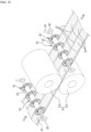
Fig. 2 is a partial perspective view showing an electrode manufacturing apparatus according to one embodiment of the present disclosure; -
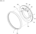
Fig. 3 is a perspective view illustrating a pressing unit of an electrode manufacturing apparatus according to one embodiment of the present disclosure; -
Fig. 4 is a perspective view showing a modified embodiment of the pressing unit ofFig. 3 ; -
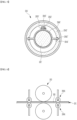
Fig. 5 is a cross-sectional view showing a ring assembly of an electrode manufacturing apparatus according to another embodiment of the present disclosure; and -
Fig. 6 is a schematic diagram showing an electrode manufacturing apparatus according to another embodiment of the present disclosure. - The present disclosure will be described in more detail below. Prior to the description, the terms or words used in the present specification and claims should not be construed as limited to ordinary or dictionary terms, and the present disclosure should be construed with meanings and concepts that are consistent with the technical idea of the present disclosure based on the principle that the inventors may appropriately define concepts of the terms to appropriately describe their own disclosure in the best way.
-
Fig. 1 is a schematic diagram showing an electrode manufacturing apparatus according to one embodiment of the present disclosure.Fig. 2 is a partial perspective view showing an electrode manufacturing apparatus according to one embodiment of the present disclosure. As shown inFig. 1 , theelectrode manufacturing apparatus 100 includes a roller-shaped unwinder 110 in which a sheet-shapedcurrent collector 101 made of a metal material (e.g., copper) for a positive electrode or a negative electrode of a secondary battery is wound. - The
current collector 101 unwound from theunwinder 110 is transferred along one direction (from left to right with reference toFig. 1 ) by the transfer unit 120 of theelectrode manufacturing apparatus 100. Here, the transfer unit 120 may include a plurality of rolls. - The electrode
active material 102 is applied (coated) onto thecurrent collector 101, which is transferred by the transfer unit 120, by using the coating unit 140 of theelectrode manufacturing apparatus 100, and the coated electrodeactive material 102 is dried through the drying unit 150 of theelectrode manufacturing apparatus 100. - The electrode
active material layer 103 dried by the drying unit 150 is rolled by therolling unit 160 of theelectrode manufacturing apparatus 100, and thecurrent collector 101 including the rolled electrodeactive material layer 103 is wound around a winder 170 of theelectrode manufacturing apparatus 100. - In the present embodiment, the coating unit 140 may include a
coating die 141 that flows out the electrodeactive material 102 toward thecurrent collector 101, and a coater roll 142 that is arranged so as to face thecoating die 141 with thecurrent collector 101 being interposed therebetween to apply tension to thecurrent collector 101. - In the present embodiment, the coating of the electrode
active material 102 by the coating unit 140 may be performed such that a plurality of electrodeactive material layers 103 are provided on thecurrent collector 101. Referring toFig. 2 , thecurrent collector 101 is provided with three rows of electrodeactive material layers 103, wherein anon-coated part 105 is maintained between the electrodeactive material layers 103 to which the electrode active material is not applied and the electrodeactive material layer 103, and between the electrodeactive material layer 103 and the edge of thecurrent collector 101. For example, thecurrent collector 101 has four rows ofnon-coated parts 105 formed therein. - Moreover, the drying unit 150 is configured to evaporate the solvent from the electrode
active material 102 to form the electrodeactive material layer 103, and therolling unit 160 may include a pair ofrollers current collector 101 interposed therebetween, and the winder 170 may be made in the shape of a roller. - Meanwhile, a
pressing unit 200 that presses thenon-coated part 105 is arranged on thecurrent collector 101 adjacent to therollers rolling unit 160, in order to prevent occurrence of defects such as a folding phenomenon on the non-coatedpart 105 due to the force generated when the electrodeactive material layer 103 is rolled by therolling unit 160. - The
pressing unit 200 may be arranged at the rear end of therolling unit 160 on the basis of the transfer direction of the current collector 101 (e.g., the arrow direction shown inFig. 2). Fig. 2 illustrates that thepressing unit 200 is arranged on both sides of therolling unit 160, that is, at the front and rear ends of therolling unit 160. - In the present embodiment, the
pressing unit 200 includes aroll member 202 that has a predetermined diameter and length and is rotated by a driving source (not shown). In addition, thepressing unit 200 includes aring assembly 204 that is detachably coupled to theroll member 202. Thering assembly 204 comes into contact with thenon-coated part 105 while rotating in conjunction with the rotation of theroll member 202, and presses thenon-coated part 105. -
Fig. 3 is a perspective view illustrating a pressing unit of an electrode manufacturing apparatus according to one embodiment of the present disclosure.Fig. 4 is a perspective view showing a modified embodiment of the pressing unit ofFig. 3 . - In the present embodiment, the
ring assembly 204 of thepressing unit 200 includes afirst ring member 2040 and asecond ring member 2042. Thefirst ring member 2040 and thesecond ring member 2042 are connected to each other, and thesecond ring member 2042 may have a circular shape having a larger diameter than thefirst ring member 2040. - In the case of the embodiment shown in
Figs. 2 and3 , thefirst ring member 2040 and thesecond ring member 2042 are fixed to each other by aconnection member 2044 disposed oppositely between thefirst ring member 2040 and thesecond ring member 2042. Thereby, thefirst ring member 2040 is spaced apart from thesecond ring member 2042 by a distance corresponding to the length of theconnection member 2044. - The
second ring member 2042 is formed in a complete ring shape, while thefirst ring member 2040 is made in a ring form in which both ends, that is, both ends disposed on the upper side with reference to the drawing are formed as free ends. Thereby, thefirst ring member 2040 can be moved by its own elastic force up to both ends while the portion connected to theconnection member 2044 is assumed as a fixed point. Theextension parts 2046 are respectively extended at both ends of thefirst ring member 2042. - The
extension part 2046 has a predetermined length and is arranged parallel to the longitudinal direction of theroll member 202, the length may be larger than the width of thefirst ring member 2040, and the width may be smaller than the distance between thefirst ring member 2040 and thesecond ring member 2042. - Further, the
respective extension parts 2046 are provided with anopening 2048 for screw coupling of thecoupling screw 2050 and thenut 2052, respectively. That is, because thecoupling screw 2050 is inserted into theopening 2048 of theextension part 2046, and coupled with thenut 2052, afirst ring member 2040 can be fixed to theroll member 202, and thefirst ring member 2040 can be spaced apart from theroll member 202 due to the release of thecoupling screw 2050 and thenut 2052. This will be explained in more detail below. - In the present disclosure, the attachment and detachment of the
first ring member 2040 to theroll member 202 cannot be performed only by the coupling structure of the above coupling screw and nut. - Meanwhile, a
third ring member 2054 having an elastic force may be coupled to thesecond ring member 2042. In the present embodiment, thethird ring member 2054 is provided as a rubber and coupled to the outer peripheral surface of thesecond ring member 2042. Of course, thethird ring member 2054 may be composed of a member made of other materials that can have an elastic force as well as rubber. As thethird ring member 2054 is formed of a material capable of having an elastic force such as rubber, it may help that thecurrent collector 101 travels smoothly. In other words, since thethird ring member 2054 has an elastic force, it can play a role of pulling thecurrent collector 101 using a frictional force during rotation in a state of being in contact with thecurrent collector 101. - Further, since the
third ring member 2054 has an elastic force, it is possible to increase the effect of applying tension to thenon-coated part 105 and widening the wrinkles. - Furthermore, since the
third ring member 2054 has an elastic force, it can be easily coupled to the outer peripheral surface of thesecond ring member 2042. As a modified embodiment, referring toFig. 4 , a protrusion part P for inserting thethird ring member 2054 is formed on the outer peripheral surface of thesecond ring member 2042, and a depressed part D into which the protrusion part P is fitted may be formed on an inner surface of thethird ring member 2054. - Referring to
Figs. 2 and3 again, the width of thesecond ring member 2042 and the width of thethird ring member 2054 may be substantially identical, and the widths of the second andthird ring members non-coated part 105. - A plurality of
ring assemblies 204 configured in this manner may be provided on theroll member 202. In this embodiment, as described above, since three rows of the active material layers 103 and four rows of thenon-coated parts 105 are formed on thecurrent collector 101, fourring assemblies 204 can be arranged on theroll member 202 at intervals corresponding to the width of theactive material layer 103 in accordance with the four rows of thenon-coated parts 105. At this time, tworing assemblies 204 can be provided on theroll member 202, so that theextension part 2046 faces in the same direction (e.g., to the left with reference toFig. 2 ), and the other tworing assemblies 204 can be provided on theroll member 202, so that theextension part 2046 faces in the same other direction (e.g., to the right with reference toFig. 2 ). - The coupling between the
ring assembly 204 and theroll member 202 is performed by inserting acoupling screw 2050 into theopening 2048 of theextension part 2046 of thefirst ring member 2040 and coupling anut 2052 thereto, in a state where thefirst ring member 2040 of thering assembly 204 is inserted into theroll member 202 and stopped at a desired position. - Due to the coupling of the
coupling screw 2050 and thenut 2052, thefirst ring member 2040 may be fixed to theroll member 202, and thus thering assembly 204 can be fixed to theroll member 202. - When the
active material layer 103 is rolled by the rollingunit 160 during manufacturing of the secondary battery electrode, thepressing unit 200 comes into contact with thenon-coated part 105 and presses thenon-coated part 105. That is, as theroll member 202 of thepressing unit 200 rotates, thering assembly 204 rotates and presses thenon-coated part 105. Therefore, even if the force of rolling of the rollingunit 160 is transmitted to thenon-coated part 105, thenon-coated part 105 can be pressed by thepressing unit 200 to maintain tension, thereby preventing defects such as a folding phenomenon. That is, thepressing unit 200 can displace theroll member 202 relative to thecurrent collector 101 by theelevation arm 300 and thecylinder 302 connected to theroll member 202, thereby adjusting the degree of tension that presses thenon-coated part 105. -
Fig. 5 is a cross-sectional view showing a ring assembly of an electrode manufacturing apparatus according to another embodiment of the present disclosure. - The ring assembly 204' of the other embodiment is constructed to be substantially identical to the ring assembly of the above-mentioned embodiment, while it is constructed by changing only the connection relationship between the first ring member 2040' and the second ring member 2042'.
- In another embodiment, a mutual connection between the first ring member 2040' and the second ring member 2042' can rotatably couple the second ring member 2042' to the first ring member 2040' or can rotatably couple the first ring member 2040' to the second ring member 2042'.
- For example, as shown in
Fig. 5 , the connection member 2044' extending from the first ring member 2040' is rotatably coupled to thegroove 2042" provided in the second ring member 2042', and the first ring member 2040' can be rotatably coupled to the second ring member 2042'. - Due to this configuration, the ring assembly 204' according to another embodiment can fix the first ring member 2040' to the roll member 202' by coupling the coupling screw 2050' and the nut 2052', even if the extension part 2046' extending from both ends of the first ring member 2040' is vertically extended from both ends between the first ring member 2040' and the second ring member 2042'.
-
Fig. 6 is a schematic diagram showing an electrode manufacturing apparatus according to another embodiment of the present disclosure. - As shown in
Fig. 6 , in another embodiment, thepressing unit 200A may be arranged so as to press not only to the non-coated part region of one side surface (e.g., upper side surface) of thecurrent collector 101 and the non-coated part region of the other side surface (e.g., the lower side surface) of thecurrent collector 101 opposing to the one side surface, as in the previously described embodiment. - The present disclosure has been described in more detail above with reference to the drawings, embodiments, and the like. However, the configurations described herein and the configurations shown in the embodiments, drawings, or the like are only one embodiment of the present disclosure and do not represent the entire spirit of the present disclosure, so it should be appreciated that there may be various equivalents and modifications that can replace the embodiments and the configurations at the time at which the present application is filed, and the scope of the present disclosure is not limited to the embodiments described below.
-
- 100: electrode manufacturing apparatus
- 101: current collector
- 102: electrode active material
- 103: electrode active material layer
- 105: non-coated part
- 110: unwinder
- 120: transfer unit
- 140: coating unit
- 150: drying unit
- 160: rolling unit
- 200: pressing unit
- 202: roll member
- 204: ring assembly
Claims (14)
- A manufacturing apparatus of an electrode for a secondary battery comprising:a transfer unit that transfers a current collector from an unwinder;a coating unit that applies an electrode active material to at least one surface of the current collector;a rolling unit that is arranged on the transfer unit and rolls the electrode active material layer composed of the electrode active material; anda pressing unit that is arranged adjacently to the rolling unit and presses the non-coated part of the current collector to which the electrode active material is not applied,wherein the pressing unit comprises,a roll member; anda ring assembly that is detachably coupled to the roll member and comes into contact with the non-coated part to press the non-coated part.
- The manufacturing apparatus of the electrode according to claim 1, wherein:the ring assembly comprises,a first ring member that is detachably fixed to the roll member; anda second ring member that has a larger diameter than the first ring member and is connected to the first ring member to press the pressing unit.
- The manufacturing apparatus of the electrode according to claim 2, wherein:
a third ring member having an elastic force is coupled to an outer peripheral surface of the second ring member. - The manufacturing apparatus of the electrode according to claim 3, wherein:
the third ring member is a rubber. - The manufacturing apparatus of the electrode according to claim 3, wherein:a depressed part is formed on the inner surface of the third ring member, and a protrusion part is formed on the outer peripheral surface of the second ring member, andthe protrusion part of the second ring member is fitted into the depressed part of the third ring member.
- The manufacturing apparatus of the electrode according to claim 2, wherein:
the first ring member is made in a form in which both ends are formed as free ends, and extension parts each extending from both ends are provided with an opening for screw coupling. - The manufacturing apparatus of the electrode according to claim 6, wherein:
the respective extension parts have a length greater than the width of the first ring member and is arranged parallel to the roll member. - The manufacturing apparatus of the electrode according to claim 6, wherein:
the first ring member is rotatably coupled to the second ring member. - The manufacturing apparatus of the electrode according to claim 8, wherein:
the respective extension parts extend vertically from both ends. - The manufacturing apparatus of the electrode according to claim 2, wherein:
a width of the second ring member is smaller than a width of the non-coated part. - The manufacturing apparatus of the electrode according to claim 1, wherein:
both ends of the roll member are connected to an elevation arm and a cylinder, respectively, so that the roll member is displaced with respect to the current collector. - The manufacturing apparatus of the electrode according to claim 1, wherein:
the ring assembly is arranged at equal intervals on the roll member and is provided by plural numbers. - The manufacturing apparatus of the electrode according to claim 1, wherein:
the pressing unit is arranged at the front and rear ends of the rolling unit, respectively. - The manufacturing apparatus of the electrode according to claim 1 or 12, wherein:
the pressing unit is configured so as to press the non-coated part of the first surface of the current collector and the non-coated part of the second surface opposing to the first surface, respectively.
Applications Claiming Priority (3)
| Application Number | Priority Date | Filing Date | Title |
|---|---|---|---|
| KR20210144526 | 2021-10-27 | ||
| KR1020220138119A KR102894078B1 (en) | 2021-10-27 | 2022-10-25 | Manufacturing apparatus of electrode for secondary battery |
| PCT/KR2022/016500 WO2023075426A1 (en) | 2021-10-27 | 2022-10-26 | Apparatus for manufacturing electrode for secondary battery |
Publications (3)
| Publication Number | Publication Date |
|---|---|
| EP4261916A1 true EP4261916A1 (en) | 2023-10-18 |
| EP4261916A4 EP4261916A4 (en) | 2024-07-31 |
| EP4261916B1 EP4261916B1 (en) | 2025-07-02 |
Family
ID=86158163
Family Applications (1)
| Application Number | Title | Priority Date | Filing Date |
|---|---|---|---|
| EP22887622.3A Active EP4261916B1 (en) | 2021-10-27 | 2022-10-26 | Manufacturing apparatus of electrode for secondary battery |
Country Status (6)
| Country | Link |
|---|---|
| US (1) | US20240128428A1 (en) |
| EP (1) | EP4261916B1 (en) |
| JP (1) | JP7697012B2 (en) |
| ES (1) | ES3037502T3 (en) |
| HU (1) | HUE072402T2 (en) |
| WO (1) | WO2023075426A1 (en) |
Families Citing this family (3)
| Publication number | Priority date | Publication date | Assignee | Title |
|---|---|---|---|---|
| DE102023114687A1 (en) * | 2023-06-05 | 2024-12-05 | Bayerische Motoren Werke Aktiengesellschaft | Method for producing at least one electrode, in particular for a storage cell for storing electrical energy |
| JP2025179754A (en) * | 2024-05-28 | 2025-12-10 | プライムプラネットエナジー&ソリューションズ株式会社 | Electrode sheet processing method and electrode sheet manufacturing device |
| JP2025179751A (en) * | 2024-05-28 | 2025-12-10 | プライムプラネットエナジー&ソリューションズ株式会社 | Electrode sheet processing method and electrode manufacturing system |
Family Cites Families (19)
| Publication number | Priority date | Publication date | Assignee | Title |
|---|---|---|---|---|
| USRE26591E (en) * | 1967-02-10 | 1969-05-27 | Split roller bearings | |
| JPH01139261A (en) * | 1987-11-26 | 1989-05-31 | Natl House Ind Co Ltd | Driving roller for lapping device |
| JPH0528990A (en) * | 1991-07-19 | 1993-02-05 | Toshiba Corp | Rolling equipment |
| US5810157A (en) * | 1995-02-15 | 1998-09-22 | Nolan; John | Conveyor apparatus for transporting a workpiece with a variable drive force |
| JP2005044539A (en) * | 2003-07-23 | 2005-02-17 | Mitsubishi Heavy Ind Ltd | Manufacturing method of secondary battery electrode and roll press device |
| KR101227356B1 (en) * | 2008-03-11 | 2013-01-28 | 히라따기꼬오 가부시키가이샤 | Carrier roller and carrier device using the same |
| KR20100047645A (en) * | 2008-10-29 | 2010-05-10 | 장재석 | An assembly of transfer roller for a board transfer apparatus |
| KR101182892B1 (en) * | 2011-05-11 | 2012-09-13 | 삼성에스디아이 주식회사 | Electrode plate and method for manufacturing electrode plate and secondary battery having the same |
| JP6115380B2 (en) * | 2013-07-29 | 2017-04-19 | 株式会社豊田自動織機 | Strip electrode manufacturing method and strip electrode cutting apparatus |
| JP2015115116A (en) * | 2013-12-09 | 2015-06-22 | 株式会社豊田自動織機 | Press apparatus and manufacturing method of electrode material |
| KR101830287B1 (en) * | 2015-06-01 | 2018-02-20 | 주식회사 엘지화학 | Electrode Rolling Device Capable of Preventing Swell or Wrinkle of Electrode Sheet by Rolling Work |
| KR102073656B1 (en) * | 2016-02-11 | 2020-02-05 | 주식회사 엘지화학 | Pressing Device Capable of Adjusting Space between Pressing Rolls |
| JP2018026334A (en) * | 2016-07-27 | 2018-02-15 | 株式会社豊田自動織機 | Electrode of power storage device, manufacturing apparatus of electrode and manufacturing method of electrode |
| CN106910896A (en) * | 2017-03-30 | 2017-06-30 | 邢台海裕锂能电池设备有限公司 | A kind of pole piece current collector stretch system of squash type |
| CN208116536U (en) * | 2018-04-02 | 2018-11-20 | 成都市银隆新能源有限公司 | A kind of pole piece rolling device |
| KR102206057B1 (en) * | 2018-11-20 | 2021-01-20 | 주식회사 엘지화학 | An electrode rolling apparatus having a heating unit for heating a non-coated portion and Manufacturing system for an electrode comprising the same |
| KR102844981B1 (en) * | 2020-02-26 | 2025-08-12 | 에스케이온 주식회사 | Apparatus for rolling electrode |
| KR102883800B1 (en) | 2020-05-21 | 2025-11-11 | 에이치디한국조선해양 주식회사 | controllable pitch propeller with locking shoe |
| KR20220138119A (en) | 2021-04-05 | 2022-10-12 | 송재문 | Manufacturing method for shielding material for electromagnetic wave and shielding material for electromagnetic wave manufactured using the same |
-
2022
- 2022-10-26 JP JP2023537691A patent/JP7697012B2/en active Active
- 2022-10-26 US US18/273,448 patent/US20240128428A1/en active Pending
- 2022-10-26 ES ES22887622T patent/ES3037502T3/en active Active
- 2022-10-26 WO PCT/KR2022/016500 patent/WO2023075426A1/en not_active Ceased
- 2022-10-26 HU HUE22887622A patent/HUE072402T2/en unknown
- 2022-10-26 EP EP22887622.3A patent/EP4261916B1/en active Active
Also Published As
| Publication number | Publication date |
|---|---|
| ES3037502T3 (en) | 2025-10-02 |
| EP4261916B1 (en) | 2025-07-02 |
| HUE072402T2 (en) | 2025-11-28 |
| WO2023075426A1 (en) | 2023-05-04 |
| US20240128428A1 (en) | 2024-04-18 |
| EP4261916A4 (en) | 2024-07-31 |
| JP7697012B2 (en) | 2025-06-23 |
| JP2024500860A (en) | 2024-01-10 |
Similar Documents
| Publication | Publication Date | Title |
|---|---|---|
| EP4261916B1 (en) | Manufacturing apparatus of electrode for secondary battery | |
| JP7642963B2 (en) | Electrode manufacturing apparatus, electrode manufacturing method, and electrode manufactured thereby | |
| EP4099426B1 (en) | ELECTRODE MANUFACTURING DEVICE | |
| CN108028359A (en) | Electrode, method for manufacturing electrode, and roll for manufacturing electrode | |
| KR20200121502A (en) | Roller assembly for electrode sheet rolling | |
| KR20150040480A (en) | Guide Roll Device Having Pressing Arms | |
| JP6499997B2 (en) | Separator manufacturing method for lithium ion secondary battery and separator slit method for lithium ion secondary battery | |
| JP2005183181A (en) | Non-aqueous electrolyte secondary battery electrode plate and method for producing the same | |
| CN116803555A (en) | Secondary battery electrode sheet rolling device, positive electrode and secondary battery manufactured using the same | |
| KR102503562B1 (en) | Apparatus for progressing web used in making electrode of secondary battery | |
| US12620614B2 (en) | Roll for supporting electrode and electrode manufacturing apparatus including the same | |
| CN113967699A (en) | Method and equipment for splicing ultrathin lithium foil or lithium strip | |
| KR102894078B1 (en) | Manufacturing apparatus of electrode for secondary battery | |
| JP2014107166A (en) | Manufacturing apparatus of electrode and manufacturing method of electrode | |
| KR102307595B1 (en) | Winding Type-Electrode Assembly Having Prismatic Cross-Sectional Structure | |
| EP4333146B1 (en) | Electrode assembly manufacturing apparatus for preventing separator folding and electrode assembly manufactured using the same | |
| CN116745925A (en) | Equipment for manufacturing electrodes for secondary batteries | |
| JP2016131944A (en) | Gravure coating apparatus | |
| JP5885888B1 (en) | Separator manufacturing method and slitting method | |
| CN215896449U (en) | A pole piece lithium supplementing device | |
| KR20200056191A (en) | Manufacturing method and manufacturing apparatus for electrode assembly | |
| KR20200046788A (en) | Roll Press Apparatus Comprising Stepped Revision Member and Method for Pressing Using the Same | |
| WO2016103758A1 (en) | Separator production method and slitting method | |
| EP4636833A1 (en) | Electrode manufacturing apparatus and electrode manufacturing method using same | |
| JP4549835B2 (en) | Guttered winding core holder and method for holding a grooved winding core with a holder |
Legal Events
| Date | Code | Title | Description |
|---|---|---|---|
| STAA | Information on the status of an ep patent application or granted ep patent |
Free format text: STATUS: THE INTERNATIONAL PUBLICATION HAS BEEN MADE |
|
| PUAI | Public reference made under article 153(3) epc to a published international application that has entered the european phase |
Free format text: ORIGINAL CODE: 0009012 |
|
| STAA | Information on the status of an ep patent application or granted ep patent |
Free format text: STATUS: REQUEST FOR EXAMINATION WAS MADE |
|
| 17P | Request for examination filed |
Effective date: 20230712 |
|
| AK | Designated contracting states |
Kind code of ref document: A1 Designated state(s): AL AT BE BG CH CY CZ DE DK EE ES FI FR GB GR HR HU IE IS IT LI LT LU LV MC ME MK MT NL NO PL PT RO RS SE SI SK SM TR |
|
| A4 | Supplementary search report drawn up and despatched |
Effective date: 20240702 |
|
| RIC1 | Information provided on ipc code assigned before grant |
Ipc: B05C 9/12 20060101ALI20240626BHEP Ipc: H01M 4/04 20060101AFI20240626BHEP |
|
| DAV | Request for validation of the european patent (deleted) | ||
| DAX | Request for extension of the european patent (deleted) | ||
| GRAP | Despatch of communication of intention to grant a patent |
Free format text: ORIGINAL CODE: EPIDOSNIGR1 |
|
| STAA | Information on the status of an ep patent application or granted ep patent |
Free format text: STATUS: GRANT OF PATENT IS INTENDED |
|
| INTG | Intention to grant announced |
Effective date: 20250227 |
|
| P01 | Opt-out of the competence of the unified patent court (upc) registered |
Free format text: CASE NUMBER: APP_13995/2025 Effective date: 20250321 |
|
| GRAS | Grant fee paid |
Free format text: ORIGINAL CODE: EPIDOSNIGR3 |
|
| GRAA | (expected) grant |
Free format text: ORIGINAL CODE: 0009210 |
|
| STAA | Information on the status of an ep patent application or granted ep patent |
Free format text: STATUS: THE PATENT HAS BEEN GRANTED |
|
| AK | Designated contracting states |
Kind code of ref document: B1 Designated state(s): AL AT BE BG CH CY CZ DE DK EE ES FI FR GB GR HR HU IE IS IT LI LT LU LV MC ME MK MT NL NO PL PT RO RS SE SI SK SM TR |
|
| REG | Reference to a national code |
Ref country code: GB Ref legal event code: FG4D |
|
| REG | Reference to a national code |
Ref country code: CH Ref legal event code: EP |
|
| REG | Reference to a national code |
Ref country code: DE Ref legal event code: R096 Ref document number: 602022017115 Country of ref document: DE |
|
| REG | Reference to a national code |
Ref country code: IE Ref legal event code: FG4D |
|
| REG | Reference to a national code |
Ref country code: ES Ref legal event code: FG2A Ref document number: 3037502 Country of ref document: ES Kind code of ref document: T3 Effective date: 20251002 |
|
| PGFP | Annual fee paid to national office [announced via postgrant information from national office to epo] |
Ref country code: BE Payment date: 20250922 Year of fee payment: 4 |
|
| PGFP | Annual fee paid to national office [announced via postgrant information from national office to epo] |
Ref country code: FR Payment date: 20250925 Year of fee payment: 4 |
|
| REG | Reference to a national code |
Ref country code: NL Ref legal event code: MP Effective date: 20250702 |
|
| PGFP | Annual fee paid to national office [announced via postgrant information from national office to epo] |
Ref country code: HU Payment date: 20251029 Year of fee payment: 4 |
|
| REG | Reference to a national code |
Ref country code: HU Ref legal event code: AG4A Ref document number: E072402 Country of ref document: HU |
|
| PG25 | Lapsed in a contracting state [announced via postgrant information from national office to epo] |
Ref country code: PT Free format text: LAPSE BECAUSE OF FAILURE TO SUBMIT A TRANSLATION OF THE DESCRIPTION OR TO PAY THE FEE WITHIN THE PRESCRIBED TIME-LIMIT Effective date: 20251103 |
|
| PG25 | Lapsed in a contracting state [announced via postgrant information from national office to epo] |
Ref country code: NL Free format text: LAPSE BECAUSE OF FAILURE TO SUBMIT A TRANSLATION OF THE DESCRIPTION OR TO PAY THE FEE WITHIN THE PRESCRIBED TIME-LIMIT Effective date: 20250702 |
|
| REG | Reference to a national code |
Ref country code: AT Ref legal event code: MK05 Ref document number: 1810296 Country of ref document: AT Kind code of ref document: T Effective date: 20250702 |
|
| PG25 | Lapsed in a contracting state [announced via postgrant information from national office to epo] |
Ref country code: IS Free format text: LAPSE BECAUSE OF FAILURE TO SUBMIT A TRANSLATION OF THE DESCRIPTION OR TO PAY THE FEE WITHIN THE PRESCRIBED TIME-LIMIT Effective date: 20251102 |
|
| PGFP | Annual fee paid to national office [announced via postgrant information from national office to epo] |
Ref country code: DE Payment date: 20250922 Year of fee payment: 4 |
|
| PG25 | Lapsed in a contracting state [announced via postgrant information from national office to epo] |
Ref country code: NO Free format text: LAPSE BECAUSE OF FAILURE TO SUBMIT A TRANSLATION OF THE DESCRIPTION OR TO PAY THE FEE WITHIN THE PRESCRIBED TIME-LIMIT Effective date: 20251002 |
|
| REG | Reference to a national code |
Ref country code: LT Ref legal event code: MG9D |
|
| PG25 | Lapsed in a contracting state [announced via postgrant information from national office to epo] |
Ref country code: AT Free format text: LAPSE BECAUSE OF FAILURE TO SUBMIT A TRANSLATION OF THE DESCRIPTION OR TO PAY THE FEE WITHIN THE PRESCRIBED TIME-LIMIT Effective date: 20250702 |
|
| PG25 | Lapsed in a contracting state [announced via postgrant information from national office to epo] |
Ref country code: FI Free format text: LAPSE BECAUSE OF FAILURE TO SUBMIT A TRANSLATION OF THE DESCRIPTION OR TO PAY THE FEE WITHIN THE PRESCRIBED TIME-LIMIT Effective date: 20250702 |
|
| PG25 | Lapsed in a contracting state [announced via postgrant information from national office to epo] |
Ref country code: HR Free format text: LAPSE BECAUSE OF FAILURE TO SUBMIT A TRANSLATION OF THE DESCRIPTION OR TO PAY THE FEE WITHIN THE PRESCRIBED TIME-LIMIT Effective date: 20250702 |
|
| PG25 | Lapsed in a contracting state [announced via postgrant information from national office to epo] |
Ref country code: GR Free format text: LAPSE BECAUSE OF FAILURE TO SUBMIT A TRANSLATION OF THE DESCRIPTION OR TO PAY THE FEE WITHIN THE PRESCRIBED TIME-LIMIT Effective date: 20251003 |
|
| PG25 | Lapsed in a contracting state [announced via postgrant information from national office to epo] |
Ref country code: SE Free format text: LAPSE BECAUSE OF FAILURE TO SUBMIT A TRANSLATION OF THE DESCRIPTION OR TO PAY THE FEE WITHIN THE PRESCRIBED TIME-LIMIT Effective date: 20250702 Ref country code: CZ Free format text: LAPSE BECAUSE OF FAILURE TO SUBMIT A TRANSLATION OF THE DESCRIPTION OR TO PAY THE FEE WITHIN THE PRESCRIBED TIME-LIMIT Effective date: 20250702 |
|
| PG25 | Lapsed in a contracting state [announced via postgrant information from national office to epo] |
Ref country code: LV Free format text: LAPSE BECAUSE OF FAILURE TO SUBMIT A TRANSLATION OF THE DESCRIPTION OR TO PAY THE FEE WITHIN THE PRESCRIBED TIME-LIMIT Effective date: 20250702 |
|
| PG25 | Lapsed in a contracting state [announced via postgrant information from national office to epo] |
Ref country code: PL Free format text: LAPSE BECAUSE OF FAILURE TO SUBMIT A TRANSLATION OF THE DESCRIPTION OR TO PAY THE FEE WITHIN THE PRESCRIBED TIME-LIMIT Effective date: 20250702 Ref country code: BG Free format text: LAPSE BECAUSE OF FAILURE TO SUBMIT A TRANSLATION OF THE DESCRIPTION OR TO PAY THE FEE WITHIN THE PRESCRIBED TIME-LIMIT Effective date: 20250702 |
|
| PG25 | Lapsed in a contracting state [announced via postgrant information from national office to epo] |
Ref country code: RS Free format text: LAPSE BECAUSE OF FAILURE TO SUBMIT A TRANSLATION OF THE DESCRIPTION OR TO PAY THE FEE WITHIN THE PRESCRIBED TIME-LIMIT Effective date: 20251002 |
|
| PGFP | Annual fee paid to national office [announced via postgrant information from national office to epo] |
Ref country code: ES Payment date: 20251117 Year of fee payment: 4 |
|
| PG25 | Lapsed in a contracting state [announced via postgrant information from national office to epo] |
Ref country code: RO Free format text: LAPSE BECAUSE OF FAILURE TO SUBMIT A TRANSLATION OF THE DESCRIPTION OR TO PAY THE FEE WITHIN THE PRESCRIBED TIME-LIMIT Effective date: 20250702 |
|
| PG25 | Lapsed in a contracting state [announced via postgrant information from national office to epo] |
Ref country code: SM Free format text: LAPSE BECAUSE OF FAILURE TO SUBMIT A TRANSLATION OF THE DESCRIPTION OR TO PAY THE FEE WITHIN THE PRESCRIBED TIME-LIMIT Effective date: 20250702 |
|
| PG25 | Lapsed in a contracting state [announced via postgrant information from national office to epo] |
Ref country code: DK Free format text: LAPSE BECAUSE OF FAILURE TO SUBMIT A TRANSLATION OF THE DESCRIPTION OR TO PAY THE FEE WITHIN THE PRESCRIBED TIME-LIMIT Effective date: 20250702 |
|
| PG25 | Lapsed in a contracting state [announced via postgrant information from national office to epo] |
Ref country code: IT Free format text: LAPSE BECAUSE OF FAILURE TO SUBMIT A TRANSLATION OF THE DESCRIPTION OR TO PAY THE FEE WITHIN THE PRESCRIBED TIME-LIMIT Effective date: 20250702 |
|
| PG25 | Lapsed in a contracting state [announced via postgrant information from national office to epo] |
Ref country code: SK Free format text: LAPSE BECAUSE OF FAILURE TO SUBMIT A TRANSLATION OF THE DESCRIPTION OR TO PAY THE FEE WITHIN THE PRESCRIBED TIME-LIMIT Effective date: 20250702 Ref country code: EE Free format text: LAPSE BECAUSE OF FAILURE TO SUBMIT A TRANSLATION OF THE DESCRIPTION OR TO PAY THE FEE WITHIN THE PRESCRIBED TIME-LIMIT Effective date: 20250702 |
|
| PLBE | No opposition filed within time limit |
Free format text: ORIGINAL CODE: 0009261 |
|
| STAA | Information on the status of an ep patent application or granted ep patent |
Free format text: STATUS: NO OPPOSITION FILED WITHIN TIME LIMIT |