EP4261800A1 - Wireless water activated lights - Google Patents
Wireless water activated lights Download PDFInfo
- Publication number
- EP4261800A1 EP4261800A1 EP23162150.9A EP23162150A EP4261800A1 EP 4261800 A1 EP4261800 A1 EP 4261800A1 EP 23162150 A EP23162150 A EP 23162150A EP 4261800 A1 EP4261800 A1 EP 4261800A1
- Authority
- EP
- European Patent Office
- Prior art keywords
- water
- block
- battery
- signal
- cavity
- Prior art date
- Legal status (The legal status is an assumption and is not a legal conclusion. Google has not performed a legal analysis and makes no representation as to the accuracy of the status listed.)
- Pending
Links
Images




Classifications
-
- G—PHYSICS
- G08—SIGNALLING
- G08B—SIGNALLING SYSTEMS, e.g. PERSONAL CALLING SYSTEMS; ORDER TELEGRAPHS; ALARM SYSTEMS
- G08B5/00—Visible signalling systems, e.g. visible personal calling systems or remote indication of seats occupied
- G08B5/002—Distress signalling devices, e.g. rescue balloons
-
- G—PHYSICS
- G08—SIGNALLING
- G08B—SIGNALLING SYSTEMS, e.g. PERSONAL CALLING SYSTEMS; ORDER TELEGRAPHS; ALARM SYSTEMS
- G08B21/00—Alarms responsive to a single specified undesired or abnormal condition and not otherwise provided for
- G08B21/18—Status alarms
- G08B21/20—Status alarms responsive to moisture
Definitions
- the present disclosure relates generally to wireless water activated light system, and more specifically to wireless water activated light systems for emergency devices.
- Water activated lights are often attached to the emergency flotation devices to assist in search and rescue during a water emergency.
- These water activated lights comprise a wired system which can fail due to wire breakage during installation of the water activated lights and/or upon deployment of the emergency flotation device. Additionally, installation of water activated lights with a wired system is often associated with production of fabric tunnels to hold the wire, which adds weight in materials and time needed to manufacture the emergency flotation device.
- the water activated transmitter assembly can comprise a casing, a cap coupled to the casing to form a cavity, a signal transmitter disposed within the cavity, a pusher block disposed within the cavity distal to the battery, and a hygroscopic block disposed within the cavity distal to the pusher block.
- the battery can be disposed distally to the signal transmitter and biased away from the signal transmitter by a spring.
- the cap can comprise an opening configured to fluidly couple the hygroscopic block with an ambient environment.
- the hygroscopic block can comprise a dry compressed towel, a dry compressed cloth, and/or a dry sponge.
- the hygroscopic block can be configured to expand with an expansion force and the expansion force can urge the battery to move proximally toward the signal transmitter.
- the expansion force can be double the spring force.
- the water activated transmitter assembly can further comprise an O-ring disposed within the cavity and in contact with the pusher block.
- the O-ring can create a seal within the casing to prevent water from entering the cavity.
- the signal transmitter is configured to transmit an output signal.
- the output signal can comprise a low frequency RF signal.
- the water emergency device system can comprise a water flotation device, a water activated transmitter assembly coupled to the water flotation device, and a wireless light assembly coupled to the water flotation device.
- the water activated transmitter assembly can comprise a casing, a cap coupled to the casing to form a cavity, a signal transmitter disposed within the cavity, a pusher block disposed within the cavity distal to the battery, and a hygroscopic block disposed within the cavity distal to the pusher block.
- the battery can be disposed distally to the signal transmitter and biased away from the signal transmitter by a spring.
- the flotation device can be a raft.
- the water activated transmitter assembly can further comprise an O-ring disposed within the cavity and in contact with the pusher block.
- the wireless light assembly can comprise a light and a battery control unit coupled to the light.
- the battery control unit can comprise a signal receiver, a processor in communication with the signal receiver and a switch, and a light battery, in communication with the switch and the light.
- the signal transmitter can be configured to transmit an output signal and the signal receiver can be configured to receive the output signal from the signal transmitter.
- the output signal can comprise a low frequency RF signal.
- the cap comprises an opening configured to fluidly couple the hygroscopic block with an ambient environment.
- the hygroscopic block can be a dry compressed towel.
- the hygroscopic block can be configured to expand with an expansion force and bias the battery in the opposite direction of the spring force.
- the expansion force can be double the spring force.
- the method can comprise disposing a hygroscopic block in a cap, coupling a pusher block to the hygroscopic block, coupling a battery to the pusher block, coupling a spring to the pusher block, coupling a transmitter to a casing, and coupling the casing to the cap.
- the method of manufacture can further comprise disposing an O-ring between the cap and the casing.
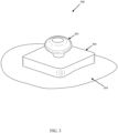
- FIG. 1 illustrates a water activated transmitter assembly 100 according to various embodiments.
- the water activated transmitter assembly 100 can comprise a casing 102, a cap 104 coupled to the casing 102 to form a cavity 106, a signal transmitter 108 disposed within the cavity 106, a battery 110 disposed within the cavity 106, a pusher block 114 disposed within the cavity and in contact with the battery 110, a spring 112 disposed between the signal transmitter 108 and the pusher block 114, and a hygroscopic block 116.
- an O-ring 120 is disposed within the cavity 106 and in contact with the pusher block 114.
- the O-ring can form a seal between the casing 102 and the cap 104 in order to prevent water from entering the cavity 106.
- the spring 112 can be disposed so as to exert a spring force which biases the battery 110 distally away from the signal transmitter 108.
- the cap 104 can comprise an opening 118.
- the opening is configured to allow water to contact the hygroscopic block 116 in response to the water activated transmitter assembly 100 being exposed to water.
- the hygroscopic block 116 can comprise any suitable hygroscopic material which expands when exposed to water, for example, a dry compressed towel, a dry compressed cloth, and/or a dry sponge material.
- the hygroscopic block 116 In response to exposing the hygroscopic block 116 to water, the hygroscopic block 116 expands and creates an expansion force which biases the pusher block 114 and the battery 110 against the spring 112 and opposes the spring force.
- the expansion force is greater than the spring force and in response to the hygroscopic block 116 expanding, hygroscopic block 116 urges the battery 110 in a proximal direction, opposing and overcoming the spring force, causing compression of the spring 113 and causing contact between the battery 110 and the signal transmitter 108.
- the signal transmitter 108 is configured to transmit an output signal 122 in response to the battery 110 making contact with the signal transmitter 108.
- the output signal 122 can comprise a low frequency radio frequency (RF) signal.
- the low frequency RF signal can have a frequency between 30 kHz and 300 kHz, or between 45 kHz and 250 kHz, or between 60 kHz and 100 kHz.
- the water activated transmitter assembly 100 can comprise a coupling means 126 to couple the water activated transmitter assembly 100 to a patch 124.
- Patch 124 can be a piece of fabric that can be attached by means such as welding or bonding using adhesives to a water flotation device, such as a raft, an emergency slide or a personal flotation device.
- Coupling means 126 can comprise any suitable coupling means, such as welding, stitching, or hanging the water activated transmitter assembly 100 on the patch 124.
- an O-ring 220 is disposed within the cavity 106 and in contact with the pusher block 114.
- the O-ring can form a seal between the casing 102 and the cap 104 in order to prevent water from entering the cavity 106.
- the spring 112 can be disposed to exert a spring force which biases the battery 110 away from the signal transmitter 108.
- the cap 104 can comprise openings 118a-118d.
- the openings 118a-118d are configured to allow water to contact the hygroscopic block 116 in response to the water activated transmitter assembly 100 being exposed to water.
- the hygroscopic block 116 can comprise the same material as hygroscopic block 116. When the hygroscopic block 116 is exposed to water, the hygroscopic block 116 expands and creates an expansion force which biases the pusher block 114 and the battery 110 against the spring 112 and opposes the spring force.
- the expansion force is greater than the spring force and in response to the hygroscopic block 116 expanding, hygroscopic block 116 urges the battery 110 distally into contact with the signal transmitter 108.
- the expansion force can be as much as double the spring force. The stronger the expansion force, the faster the battery can contact the transmitter.
- the signal transmitter 108 can have the same properties as signal transmitter 108.
- FIG. 2A illustrates the water activated transmitter assembly 100 prior to exposing the hygroscopic block 116 to water to activate the signal transmitter 108.
- FIG. 2B illustrates the water activated transmitter assembly 100 after the hygroscopic block 116 is exposed to water and the hygroscopic block 116 expands to bias the battery 110 into contact with the signal transmitter 108, thus activating the signal transmitter 108 to send an output signal such as output signal 122.
- the wireless light assembly 300 can comprise a light 302 coupled to a battery control unit 304.
- the battery control unit 304 can be coupled to a patch 324.
- Patch 324 can be a piece of fabric that can be attached by means such as welding or bonding using adhesives to a water flotation device, such as a raft, an emergency slide or a personal flotation.
- the light 302 can be an LED, an incandescent bulb, a halogen bulb, and a fluorescent bulb.
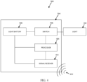
- FIG. 4 further illustrates a block diagram of the components of the wireless light assembly 300.
- the battery control unit 304 can comprise a signal receiver 402, a processor 404 in communication with the signal receiver 402 and a switch 406, and a light battery 408 in communication with the signal receiver, the processor, the switch, and the light.
- the light battery 408 can power the processor 404 and the signal receiver 402. In various embodiments, the light battery 408 may not power the processor 404 and the signal receiver 402 until the water flotation device is deployed or inflated.
- the signal receiver 402 can be configured to receive an output signal 422. In various embodiments, output signal 422 can be the same output signal as output signal 122 from signal transmitters 108 and 108. In various embodiments, when the signal receiver 402 receives the output signal 422, the signal receiver then sends a command to processor 404 to close switch 406. Closing switch 406 completes the connection between the light battery 408 and the light 302, and the light 302 is then powered on.
- a water emergency device system 500 is illustrated.
- the water emergency device system 500 comprises a water flotation device, a water activated transmitter assembly 504, and a wireless light assembly 506.
- the water flotation device is illustrated as a raft 502.
- the water flotation device can comprise any personal flotation device, such as a life jacket or floaties, or an inflatable slide used in aircraft emergencies.
- the water activated transmitter assembly 504 can be the water activated transmitter assembly 100.
- the wireless light assembly 506 can be the wireless light assembly 300.
- the raft 502 can comprise a pillow tube 508 coupled to a lower tube 510, and the lower tube 510 can be coupled to an upper tube 512.
- the water activated transmitter assembly 504 can be coupled to the raft 502 at the pillow tube 508. Coupling the water activated transmitter assembly 504 to the pillow tube 508 helps to quickly expose the water activated transmitter assembly 504 to water if the raft 502 is placed in a body of water.
- the wireless light assembly 506 can be coupled to the raft 502 at the upper tube 512. Coupling the wireless light assembly 506 to the upper tube 512 allows for the wireless light assembly 506 to be more visible when the wireless light assembly 506 is powered on.
- FIG. 5 illustrates one wireless light assembly 506, however, in various embodiments, multiple wireless light assemblies can be coupled to the water flotation device. In various embodiments, multiple wireless light assemblies can be powered on by one water activated transmitter assembly.
- Method of manufacture 600 includes the steps of disposing a hygroscopic block (shown as hygroscopic block 116) in a cap (shown as cap 104) (step 602), coupling a pusher block (shown as pusher block 114) to the hygroscopic block (step 604), coupling a battery (shown as battery 110) to the pusher block (step 606), coupling a spring (shown as spring 112) to the pusher block (step 608), coupling a signal transmitter (shown as signal transmitter 108) to a casing (shown as casing 102) (step 610) and coupling the casing to the cap (step 612).
- the method of manufacture 600 further comprises disposing an O-ring between the cap and the casing prior to step 612 to create a seal when the cap and casing are coupled together.
- the cap and the casing can comprise grooves. The grooves can be used to couple the cap and the casing together in step 612 by screwing the casing into the cap.
- references to "various embodiments”, “one embodiment”, “an embodiment”, “an example embodiment”, etc. indicate that the embodiment described may include a particular feature, structure, or characteristic, but every embodiment may not necessarily include the particular feature, structure, or characteristic. Moreover, such phrases are not necessarily referring to the same embodiment. Further, when a particular feature, structure, or characteristic is described in connection with an embodiment, it is submitted that it is within the knowledge of one skilled in the art to affect such feature, structure, or characteristic in connection with other embodiments whether or not explicitly described. After reading the description, it will be apparent to one skilled in the relevant art(s) how to implement the disclosure in alternative embodiments.
Landscapes
- Physics & Mathematics (AREA)
- General Physics & Mathematics (AREA)
- Business, Economics & Management (AREA)
- Emergency Management (AREA)
- Transmitters (AREA)
Abstract
Description
- This application claims priority to, and the benefit of,
India Patent Application No. 202241019965, filed April 1, 2022 - The present disclosure relates generally to wireless water activated light system, and more specifically to wireless water activated light systems for emergency devices.
- Many aircraft have emergency flotation devices for use in water emergencies. Water activated lights are often attached to the emergency flotation devices to assist in search and rescue during a water emergency. These water activated lights comprise a wired system which can fail due to wire breakage during installation of the water activated lights and/or upon deployment of the emergency flotation device. Additionally, installation of water activated lights with a wired system is often associated with production of fabric tunnels to hold the wire, which adds weight in materials and time needed to manufacture the emergency flotation device.
- A water activated transmitter assembly is disclosed herein. In various embodiments, the water activated transmitter assembly can comprise a casing, a cap coupled to the casing to form a cavity, a signal transmitter disposed within the cavity, a pusher block disposed within the cavity distal to the battery, and a hygroscopic block disposed within the cavity distal to the pusher block. The battery can be disposed distally to the signal transmitter and biased away from the signal transmitter by a spring. In various embodiments, the cap can comprise an opening configured to fluidly couple the hygroscopic block with an ambient environment. The hygroscopic block can comprise a dry compressed towel, a dry compressed cloth, and/or a dry sponge. The hygroscopic block can be configured to expand with an expansion force and the expansion force can urge the battery to move proximally toward the signal transmitter. The expansion force can be double the spring force.
- In various embodiments, the water activated transmitter assembly can further comprise an O-ring disposed within the cavity and in contact with the pusher block. The O-ring can create a seal within the casing to prevent water from entering the cavity. In various embodiments, the signal transmitter is configured to transmit an output signal. The output signal can comprise a low frequency RF signal.
- A water emergency device system is disclosed herein in various embodiments, the water emergency device system can comprise a water flotation device, a water activated transmitter assembly coupled to the water flotation device, and a wireless light assembly coupled to the water flotation device. The water activated transmitter assembly can comprise a casing, a cap coupled to the casing to form a cavity, a signal transmitter disposed within the cavity, a pusher block disposed within the cavity distal to the battery, and a hygroscopic block disposed within the cavity distal to the pusher block. The battery can be disposed distally to the signal transmitter and biased away from the signal transmitter by a spring. The flotation device can be a raft. The water activated transmitter assembly can further comprise an O-ring disposed within the cavity and in contact with the pusher block.
- In various embodiments, the wireless light assembly can comprise a light and a battery control unit coupled to the light. The battery control unit can comprise a signal receiver, a processor in communication with the signal receiver and a switch, and a light battery, in communication with the switch and the light. In various embodiments, the signal transmitter can be configured to transmit an output signal and the signal receiver can be configured to receive the output signal from the signal transmitter. The output signal can comprise a low frequency RF signal.
- In various embodiments, the cap comprises an opening configured to fluidly couple the hygroscopic block with an ambient environment. In various embodiments, the hygroscopic block can be a dry compressed towel. The hygroscopic block can be configured to expand with an expansion force and bias the battery in the opposite direction of the spring force. The expansion force can be double the spring force.
- An exemplary method of manufacture for a water activated transmitter assembly is disclosed herein. In various embodiments, the method can comprise disposing a hygroscopic block in a cap, coupling a pusher block to the hygroscopic block, coupling a battery to the pusher block, coupling a spring to the pusher block, coupling a transmitter to a casing, and coupling the casing to the cap. In various embodiment, the method of manufacture can further comprise disposing an O-ring between the cap and the casing.
- The foregoing features and elements may be combined in various combinations without exclusivity, unless expressly indicated otherwise. These features and elements as well as the operation thereof will become more apparent in light of the following description and the accompanying drawings. It should be understood, however, the following description and drawings are intended to be exemplary in nature and non-limiting.
- The accompanying drawings are included to provide a further understanding of the present disclosure and are incorporated in, and constitute a part of, this specification, illustrate various embodiments, and together with the description, serve to explain the principles of the disclosure.
-
FIG. 1 illustrates a water activated transmitter assembly, in accordance with various embodiments; -
FIG. 2A illustrates the cross-sectional view of a water activated transmitter assembly before activation, in accordance with various embodiments; -
FIG. 2B illustrates the cross-sectional view of a water activated transmitter assembly after activation, in accordance with various embodiments; -
FIG. 3 illustrates a wireless light assembly, in accordance with various embodiments; -
FIG. 4 illustrates a block diagram of the components of the wireless light assembly, in accordance with various embodiments; -
FIG. 5 illustrates a side view of a water emergency device system, in accordance with various embodiments; and -
FIG. 6 illustrates a method of manufacture of a water activated transmitter assembly, in accordance with various embodiments. - The detailed description of exemplary embodiments herein makes reference to the accompanying drawings, which show exemplary embodiments by way of illustration. While these exemplary embodiments are described in sufficient detail to enable those skilled in the art to practice the disclosure, it should be understood that other embodiments may be realized and that logical changes and adaptations in design and construction may be made in accordance with this disclosure and the teachings herein. Thus, the detailed description herein is presented for purposes of illustration only and not of limitation. The scope of the disclosure is defined by the appended claims. For example, the steps recited in any of the method or process descriptions may be executed in any order and are not necessarily limited to the order presented. Furthermore, any reference to singular includes plural embodiments, and any reference to more than one component or step may include a singular embodiment or step. Also, any reference to attached, fixed, connected or the like may include permanent, removable, temporary, partial, full and/or any other possible attachment option. Additionally, any reference to without contact (or similar phrases) may also include reduced contact or minimal contact.
-
FIG. 1 illustrates a water activatedtransmitter assembly 100 according to various embodiments. The water activatedtransmitter assembly 100 can comprise acasing 102, acap 104 coupled to thecasing 102 to form acavity 106, asignal transmitter 108 disposed within thecavity 106, abattery 110 disposed within thecavity 106, apusher block 114 disposed within the cavity and in contact with thebattery 110, aspring 112 disposed between thesignal transmitter 108 and thepusher block 114, and ahygroscopic block 116. In various embodiments, an O-ring 120 is disposed within thecavity 106 and in contact with thepusher block 114. The O-ring can form a seal between thecasing 102 and thecap 104 in order to prevent water from entering thecavity 106. Thespring 112 can be disposed so as to exert a spring force which biases thebattery 110 distally away from thesignal transmitter 108. - In various embodiments, the
cap 104 can comprise anopening 118. The opening is configured to allow water to contact thehygroscopic block 116 in response to the water activatedtransmitter assembly 100 being exposed to water. In various embodiments, there can bemultiple openings 118 or the openings may comprise one, large opening. In various embodiments, thehygroscopic block 116 can comprise any suitable hygroscopic material which expands when exposed to water, for example, a dry compressed towel, a dry compressed cloth, and/or a dry sponge material. In response to exposing thehygroscopic block 116 to water, thehygroscopic block 116 expands and creates an expansion force which biases thepusher block 114 and thebattery 110 against thespring 112 and opposes the spring force. In various embodiments, the expansion force is greater than the spring force and in response to thehygroscopic block 116 expanding,hygroscopic block 116 urges thebattery 110 in a proximal direction, opposing and overcoming the spring force, causing compression of the spring 113 and causing contact between thebattery 110 and thesignal transmitter 108. - The
signal transmitter 108 is configured to transmit anoutput signal 122 in response to thebattery 110 making contact with thesignal transmitter 108. In various embodiments, theoutput signal 122 can comprise a low frequency radio frequency (RF) signal. The low frequency RF signal can have a frequency between 30 kHz and 300 kHz, or between 45 kHz and 250 kHz, or between 60 kHz and 100 kHz. - The water activated
transmitter assembly 100 can comprise a coupling means 126 to couple the water activatedtransmitter assembly 100 to apatch 124.Patch 124 can be a piece of fabric that can be attached by means such as welding or bonding using adhesives to a water flotation device, such as a raft, an emergency slide or a personal flotation device. Coupling means 126 can comprise any suitable coupling means, such as welding, stitching, or hanging the water activatedtransmitter assembly 100 on thepatch 124. - In reference to
FIG. 2A andFIG. 2B , a cross-section of the water activatedtransmitter assembly 100 is illustrated according to various embodiments. In various embodiments, an O-ring 220 is disposed within thecavity 106 and in contact with thepusher block 114. The O-ring can form a seal between thecasing 102 and thecap 104 in order to prevent water from entering thecavity 106. Thespring 112 can be disposed to exert a spring force which biases thebattery 110 away from thesignal transmitter 108. - In various embodiments, the
cap 104 can compriseopenings 118a-118d. Theopenings 118a-118d are configured to allow water to contact thehygroscopic block 116 in response to the water activatedtransmitter assembly 100 being exposed to water. In various embodiments, thehygroscopic block 116 can comprise the same material ashygroscopic block 116. When thehygroscopic block 116 is exposed to water, thehygroscopic block 116 expands and creates an expansion force which biases thepusher block 114 and thebattery 110 against thespring 112 and opposes the spring force. In various embodiments, the expansion force is greater than the spring force and in response to thehygroscopic block 116 expanding,hygroscopic block 116 urges thebattery 110 distally into contact with thesignal transmitter 108. In various embodiments, the expansion force can be as much as double the spring force. The stronger the expansion force, the faster the battery can contact the transmitter. - In various embodiments, the
signal transmitter 108 can have the same properties assignal transmitter 108.FIG. 2A illustrates the water activatedtransmitter assembly 100 prior to exposing thehygroscopic block 116 to water to activate thesignal transmitter 108.FIG. 2B illustrates the water activatedtransmitter assembly 100 after thehygroscopic block 116 is exposed to water and thehygroscopic block 116 expands to bias thebattery 110 into contact with thesignal transmitter 108, thus activating thesignal transmitter 108 to send an output signal such asoutput signal 122. - In reference to
FIG. 3 andFIG. 4 , a wirelesslight assembly 300 is illustrated according to various embodiments. In various embodiments, the wirelesslight assembly 300 can comprise a light 302 coupled to abattery control unit 304. Thebattery control unit 304 can be coupled to apatch 324.Patch 324 can be a piece of fabric that can be attached by means such as welding or bonding using adhesives to a water flotation device, such as a raft, an emergency slide or a personal flotation. In various embodiments, the light 302 can be an LED, an incandescent bulb, a halogen bulb, and a fluorescent bulb.FIG. 4 further illustrates a block diagram of the components of the wirelesslight assembly 300. In various embodiments, thebattery control unit 304 can comprise asignal receiver 402, aprocessor 404 in communication with thesignal receiver 402 and aswitch 406, and alight battery 408 in communication with the signal receiver, the processor, the switch, and the light. - In various embodiments, the
light battery 408 can power theprocessor 404 and thesignal receiver 402. In various embodiments, thelight battery 408 may not power theprocessor 404 and thesignal receiver 402 until the water flotation device is deployed or inflated. Thesignal receiver 402 can be configured to receive anoutput signal 422. In various embodiments,output signal 422 can be the same output signal as output signal 122 fromsignal transmitters signal receiver 402 receives theoutput signal 422, the signal receiver then sends a command toprocessor 404 to closeswitch 406.Closing switch 406 completes the connection between thelight battery 408 and the light 302, and the light 302 is then powered on. - In reference to
FIG. 5 , a wateremergency device system 500 is illustrated. In various embodiments, the wateremergency device system 500 comprises a water flotation device, a water activatedtransmitter assembly 504, and a wirelesslight assembly 506. In various embodiments, the water flotation device is illustrated as araft 502. In various embodiments, the water flotation device can comprise any personal flotation device, such as a life jacket or floaties, or an inflatable slide used in aircraft emergencies. In various embodiments, the water activatedtransmitter assembly 504 can be the water activatedtransmitter assembly 100. In various embodiments, the wirelesslight assembly 506 can be the wirelesslight assembly 300. In various embodiments, theraft 502 can comprise apillow tube 508 coupled to alower tube 510, and thelower tube 510 can be coupled to anupper tube 512. - In various embodiments, the water activated
transmitter assembly 504 can be coupled to theraft 502 at thepillow tube 508. Coupling the water activatedtransmitter assembly 504 to thepillow tube 508 helps to quickly expose the water activatedtransmitter assembly 504 to water if theraft 502 is placed in a body of water. In various embodiments, the wirelesslight assembly 506 can be coupled to theraft 502 at theupper tube 512. Coupling the wirelesslight assembly 506 to theupper tube 512 allows for the wirelesslight assembly 506 to be more visible when the wirelesslight assembly 506 is powered on.FIG. 5 illustrates one wirelesslight assembly 506, however, in various embodiments, multiple wireless light assemblies can be coupled to the water flotation device. In various embodiments, multiple wireless light assemblies can be powered on by one water activated transmitter assembly. - With reference to
FIG. 2 andFIG. 6 , a method ofmanufacture 600 for forming a water activated transmitter assembly is disclosed. Method ofmanufacture 600 includes the steps of disposing a hygroscopic block (shown as hygroscopic block 116) in a cap (shown as cap 104) (step 602), coupling a pusher block (shown as pusher block 114) to the hygroscopic block (step 604), coupling a battery (shown as battery 110) to the pusher block (step 606), coupling a spring (shown as spring 112) to the pusher block (step 608), coupling a signal transmitter (shown as signal transmitter 108) to a casing (shown as casing 102) (step 610) and coupling the casing to the cap (step 612). In various embodiments, the method ofmanufacture 600 further comprises disposing an O-ring between the cap and the casing prior to step 612 to create a seal when the cap and casing are coupled together. In various embodiments, the cap and the casing can comprise grooves. The grooves can be used to couple the cap and the casing together instep 612 by screwing the casing into the cap. - Benefits, other advantages, and solutions to problems have been described herein with regard to specific embodiments. Furthermore, the connecting lines shown in the various figures contained herein are intended to represent exemplary functional relationships and/or physical couplings between the various elements. It should be noted that many alternative or additional functional relationships or physical connections may be present in a practical system. However, the benefits, advantages, solutions to problems, and any elements that may cause any benefit, advantage, or solution to occur or become more pronounced are not to be construed as critical, required, or essential features or elements of the disclosure. The scope of the disclosure is accordingly to be limited by nothing other than the appended claims, in which reference to an element in the singular is not intended to mean "one and only one" unless explicitly so stated, but rather "one or more." Moreover, where a phrase similar to "at least one of A, B, or C" is used in the claims, it is intended that the phrase be interpreted to mean that A alone may be present in an embodiment, B alone may be present in an embodiment, C alone may be present in an embodiment, or that any combination of the elements A, B and C may be present in a single embodiment; for example, A and B, A and C, B and C, or A and B and C.
- Systems, methods, and are provided herein. In the detailed description herein, references to "various embodiments", "one embodiment", "an embodiment", "an example embodiment", etc., indicate that the embodiment described may include a particular feature, structure, or characteristic, but every embodiment may not necessarily include the particular feature, structure, or characteristic. Moreover, such phrases are not necessarily referring to the same embodiment. Further, when a particular feature, structure, or characteristic is described in connection with an embodiment, it is submitted that it is within the knowledge of one skilled in the art to affect such feature, structure, or characteristic in connection with other embodiments whether or not explicitly described. After reading the description, it will be apparent to one skilled in the relevant art(s) how to implement the disclosure in alternative embodiments.
- Furthermore, no element, component, or method step in the present disclosure is intended to be dedicated to the public regardless of whether the element, component, or method step is explicitly recited in the claims. As used herein, the terms "comprises", "comprising", or any other variation thereof, are intended to cover a non-exclusive inclusion, such that a process, method, article, or that comprises a list of elements does not include only those elements but may include other elements not expressly listed or inherent to such process, method, article, or apparatus.
Claims (15)
- A water activated transmitter assembly, comprising:a casing (102);a cap (104) coupled to the casing (102) to form a cavity (106);a signal transmitter (108) disposed within the cavity (106);a battery (110) disposed within the cavity (106), wherein the battery (110) is disposed distally to the signal transmitter (108) and biased away from the signal transmitter (108) by a spring;a pusher block (114) disposed within the cavity (106) distal to the battery (110); anda hygroscopic block (116) disposed within the cavity (106) and distal to the pusher block (114).
- The water activated transmitter assembly of claim 1, wherein the cap (104) comprises an opening configured to fluidly couple the hygroscopic block (116) with an ambient environment outside the casing (102).
- The water activated transmitter assembly of claim 1 or 2, wherein the water activated transmitter assembly further comprises an O-ring disposed within the cavity (106) and in contact with the pusher block (114).
- The water activated transmitter assembly of any preceding claim, wherein the signal transmitter (108) is configured to transmit an output signal.
- The water activated transmitter assembly of any preceding claim, wherein the output signal comprises a low frequency RF signal.
- The water activated transmitter assembly of any preceding claim, wherein the hygroscopic block (116) comprises a dry compressed towel, a dry compressed cloth, and/or a dry sponge material.
- The water activated transmitter assembly of any preceding claim, wherein the hygroscopic block (116) is configured to expand with an expansion force and urge the battery (110) to move proximally toward the signal transmitter (108), and optionally wherein the expansion force is double the spring force.
- A water emergency device system, comprising:a water flotation device;a water activated transmitter assembly coupled to the water flotation device, wherein the water activated transmitter assembly comprises:a casing (102);a cap (104) coupled to the casing (102) to form a cavity (106);a signal transmitter (108) disposed within the cavity (106);a battery (110) disposed within the cavity (106), wherein the battery (110) is disposed distally to the signal transmitter (108) and biased away from the signal transmitter (108) by a spring;a pusher block (114) disposed within the cavity (106) distal to the battery (110); anda hygroscopic block (116) disposed within the cavity (106) and distal to the pusher block (114) a wireless light assembly coupled to the water flotation device.
- The water emergency device system of claim 8, wherein the wireless light assembly comprises:a light; anda battery control unit coupled to the light.
- The water emergency device system of claim 8 or 9, wherein the battery control unit comprises:a signal receiver;a processor, in communication with the signal receiver and a switch; anda light battery, in communication with the switch and the light.
- The water emergency device system of any of claims 8 to 10, wherein the signal transmitter (108) is configured to transmit an output signal and the signal receiver is configured to receive the output signal from the signal transmitter (108).
- The water emergency device system of any of claims 8 to 11, wherein the output signal comprises a low frequency RF signal, and/or wherein the water flotation device is a raft, and/or wherein the cap (104) can comprise an opening configured to fluidly couple the hygroscopic block (116) with an ambient environment, and/or wherein the water activated transmitter assembly further comprises an O-ring disposed within the cavity (106) and in contact with the pusher block (114).
- The water emergency device system of any of claims 8 to 12, wherein the hygroscopic block (116) comprises a dry compressed towel, and optionally wherein the hygroscopic block (116) is configured to expand with an expansion force and urge the battery (110) to move proximally toward the signal transmitter (108).
- A method of manufacture for a water activated transmitter assembly, the steps comprising:disposing a hygroscopic block (116) in a cap (104);coupling a pusher block (114) to the hygroscopic block (116);coupling a battery (110) to the pusher block (114);coupling a spring to the pusher block (114);coupling a signal transmitter (108) to a casing (102); andcoupling the casing (102) to the cap (104).
- The method of manufacture of claim 14, further comprising disposing an O-ring between the cap (104) and the casing (102).
Applications Claiming Priority (2)
| Application Number | Priority Date | Filing Date | Title |
|---|---|---|---|
| IN202241019965 | 2022-04-01 | ||
| US17/850,801 US12140454B2 (en) | 2022-04-01 | 2022-06-27 | Wireless water activated lights |
Publications (1)
| Publication Number | Publication Date |
|---|---|
| EP4261800A1 true EP4261800A1 (en) | 2023-10-18 |
Family
ID=85703823
Family Applications (1)
| Application Number | Title | Priority Date | Filing Date |
|---|---|---|---|
| EP23162150.9A Pending EP4261800A1 (en) | 2022-04-01 | 2023-03-15 | Wireless water activated lights |
Country Status (1)
| Country | Link |
|---|---|
| EP (1) | EP4261800A1 (en) |
Citations (3)
| Publication number | Priority date | Publication date | Assignee | Title |
|---|---|---|---|---|
| US3280549A (en) * | 1965-09-23 | 1966-10-25 | Hsu Jui-Cheng | Release mechanism powered by water immerged expandable cartridge |
| US20160272287A1 (en) * | 2014-06-06 | 2016-09-22 | Sirius Signal Co. | Visual distress signal device |
| US20190333356A1 (en) * | 2018-04-30 | 2019-10-31 | Norman Boyle | Water safety alarm and supervision aid including methodology embodied in the alarm for alerting a third party via a communications network |
-
2023
- 2023-03-15 EP EP23162150.9A patent/EP4261800A1/en active Pending
Patent Citations (3)
| Publication number | Priority date | Publication date | Assignee | Title |
|---|---|---|---|---|
| US3280549A (en) * | 1965-09-23 | 1966-10-25 | Hsu Jui-Cheng | Release mechanism powered by water immerged expandable cartridge |
| US20160272287A1 (en) * | 2014-06-06 | 2016-09-22 | Sirius Signal Co. | Visual distress signal device |
| US20190333356A1 (en) * | 2018-04-30 | 2019-10-31 | Norman Boyle | Water safety alarm and supervision aid including methodology embodied in the alarm for alerting a third party via a communications network |
Similar Documents
| Publication | Publication Date | Title |
|---|---|---|
| US9619977B2 (en) | Deployable beacon | |
| US10351251B2 (en) | Audio evacuation system readiness indicator | |
| EP4261800A1 (en) | Wireless water activated lights | |
| JP2005501686A (en) | Seal assembly with lip for prosthetic leg shaft | |
| ES2025718T3 (en) | DEPLOYMENT DEVICE, DEPENDENT ON AIR PRESSURE, FOR A PARACHUTE. | |
| CA1218611A (en) | Delayed restraint release device for inflatable escape slides | |
| US12140454B2 (en) | Wireless water activated lights | |
| US2380587A (en) | Distress signal device for aircraft, etc. | |
| JP2009028245A (en) | Capsule-shaped medical treatment device | |
| US10774821B2 (en) | Portable inflation device | |
| US4662850A (en) | Life preserving device with pressure responsive switch | |
| KR101046468B1 (en) | Vacuum suction port | |
| US6805071B2 (en) | Man overboard locator device | |
| WO2016048858A1 (en) | Safety, rescue, and recovery apparatus and method | |
| EP4105127A1 (en) | Automatic readiness indication for aircraft emergency evacuation | |
| KR102165241B1 (en) | Position tracking life jacket minimizing battery power consumption | |
| CN221914614U (en) | Aircraft slide evacuation prompting system | |
| CN111694267A (en) | Wearing equipment with elastic structure | |
| US10577113B2 (en) | Using two or more centralized circuit regulated circuit control module | |
| EP4242109A1 (en) | Stretch sensor assembly and method of assembling stretch sensor assemblies for evacuation system inflatables | |
| CN210727817U (en) | Wound pressurization hemostasis device after groin operation | |
| CN212787711U (en) | Wearable equipment and watchband thereof | |
| CN108082443B (en) | Redundant layer for inflatable evacuation components | |
| CN114391700B (en) | Wearable devices | |
| US5366055A (en) | Coupling assembly component |
Legal Events
| Date | Code | Title | Description |
|---|---|---|---|
| PUAI | Public reference made under article 153(3) epc to a published international application that has entered the european phase |
Free format text: ORIGINAL CODE: 0009012 |
|
| STAA | Information on the status of an ep patent application or granted ep patent |
Free format text: STATUS: THE APPLICATION HAS BEEN PUBLISHED |
|
| AK | Designated contracting states |
Kind code of ref document: A1 Designated state(s): AL AT BE BG CH CY CZ DE DK EE ES FI FR GB GR HR HU IE IS IT LI LT LU LV MC ME MK MT NL NO PL PT RO RS SE SI SK SM TR |
|
| STAA | Information on the status of an ep patent application or granted ep patent |
Free format text: STATUS: REQUEST FOR EXAMINATION WAS MADE |
|
| 17P | Request for examination filed |
Effective date: 20240409 |
|
| RBV | Designated contracting states (corrected) |
Designated state(s): AL AT BE BG CH CY CZ DE DK EE ES FI FR GB GR HR HU IE IS IT LI LT LU LV MC ME MK MT NL NO PL PT RO RS SE SI SK SM TR |
|
| STAA | Information on the status of an ep patent application or granted ep patent |
Free format text: STATUS: EXAMINATION IS IN PROGRESS |
|
| 17Q | First examination report despatched |
Effective date: 20251021 |