EP4261792A1 - Procédé de détermination d'une boîte englobante modélisant un véhicule en trois dimensions - Google Patents
Procédé de détermination d'une boîte englobante modélisant un véhicule en trois dimensions Download PDFInfo
- Publication number
- EP4261792A1 EP4261792A1 EP23166393.1A EP23166393A EP4261792A1 EP 4261792 A1 EP4261792 A1 EP 4261792A1 EP 23166393 A EP23166393 A EP 23166393A EP 4261792 A1 EP4261792 A1 EP 4261792A1
- Authority
- EP
- European Patent Office
- Prior art keywords
- point
- vehicle
- image
- template
- bounding box
- Prior art date
- Legal status (The legal status is an assumption and is not a legal conclusion. Google has not performed a legal analysis and makes no representation as to the accuracy of the status listed.)
- Pending
Links
Images


Classifications
-
- G—PHYSICS
- G06—COMPUTING OR CALCULATING; COUNTING
- G06V—IMAGE OR VIDEO RECOGNITION OR UNDERSTANDING
- G06V20/00—Scenes; Scene-specific elements
- G06V20/50—Context or environment of the image
- G06V20/52—Surveillance or monitoring of activities, e.g. for recognising suspicious objects
- G06V20/54—Surveillance or monitoring of activities, e.g. for recognising suspicious objects of traffic, e.g. cars on the road, trains or boats
-
- G—PHYSICS
- G06—COMPUTING OR CALCULATING; COUNTING
- G06T—IMAGE DATA PROCESSING OR GENERATION, IN GENERAL
- G06T7/00—Image analysis
- G06T7/70—Determining position or orientation of objects or cameras
- G06T7/73—Determining position or orientation of objects or cameras using feature-based methods
-
- G—PHYSICS
- G06—COMPUTING OR CALCULATING; COUNTING
- G06V—IMAGE OR VIDEO RECOGNITION OR UNDERSTANDING
- G06V10/00—Arrangements for image or video recognition or understanding
- G06V10/20—Image preprocessing
- G06V10/25—Determination of region of interest [ROI] or a volume of interest [VOI]
-
- G—PHYSICS
- G06—COMPUTING OR CALCULATING; COUNTING
- G06V—IMAGE OR VIDEO RECOGNITION OR UNDERSTANDING
- G06V10/00—Arrangements for image or video recognition or understanding
- G06V10/40—Extraction of image or video features
- G06V10/62—Extraction of image or video features relating to a temporal dimension, e.g. time-based feature extraction; Pattern tracking
-
- G—PHYSICS
- G06—COMPUTING OR CALCULATING; COUNTING
- G06V—IMAGE OR VIDEO RECOGNITION OR UNDERSTANDING
- G06V10/00—Arrangements for image or video recognition or understanding
- G06V10/70—Arrangements for image or video recognition or understanding using pattern recognition or machine learning
- G06V10/74—Image or video pattern matching; Proximity measures in feature spaces
- G06V10/75—Organisation of the matching processes, e.g. simultaneous or sequential comparisons of image or video features; Coarse-fine approaches, e.g. multi-scale approaches; using context analysis; Selection of dictionaries
- G06V10/755—Deformable models or variational models, e.g. snakes or active contours
- G06V10/7553—Deformable models or variational models, e.g. snakes or active contours based on shape, e.g. active shape models [ASM]
-
- G—PHYSICS
- G06—COMPUTING OR CALCULATING; COUNTING
- G06V—IMAGE OR VIDEO RECOGNITION OR UNDERSTANDING
- G06V10/00—Arrangements for image or video recognition or understanding
- G06V10/70—Arrangements for image or video recognition or understanding using pattern recognition or machine learning
- G06V10/74—Image or video pattern matching; Proximity measures in feature spaces
- G06V10/761—Proximity, similarity or dissimilarity measures
-
- G—PHYSICS
- G06—COMPUTING OR CALCULATING; COUNTING
- G06T—IMAGE DATA PROCESSING OR GENERATION, IN GENERAL
- G06T2207/00—Indexing scheme for image analysis or image enhancement
- G06T2207/10—Image acquisition modality
- G06T2207/10016—Video; Image sequence
Definitions
- the invention relates to the field of three-dimensional modeling of objects of interest in images, in particular of vehicles in a road context, the images coming from a fixed camera whose field of vision includes a lane of circulation.
- Two-dimensional modeling of vehicles in images is known from the state of the art.
- a vehicle is modeled by a rectangle. This type of modeling does not make it possible to correctly determine the positioning of a vehicle in relation to an offense line or in relation to another vehicle.
- neural networks it is known from the state of the art to use neural networks to model a vehicle in three dimensions, from a two-dimensional modeling of said vehicle in images.
- a first problem is the training of these neural networks.
- the images available to train such neural networks are mostly images whose viewing angle is not that of a fixed camera such as a road radar, but rather images from on-board cameras. on vehicles.
- a second problem is the image processing time which is too long.
- the invention aims to resolve the aforementioned problems of the state of the art by proposing a method for determining a bounding box modeling a vehicle in three dimensions without using neural networks.
- the real characteristic point is a projection by the inverse mathematical function of a characteristic image point belonging to the rectangular box and being determined from the rectangular box and the library, by making the approximation that the real characteristic point is located in a general plane including the vehicle lane.
- the calculator determines the bounding box by modifying the dimensions of the selected template into a final template, so as to minimize a gap between a rectangle circumscribed by the projection in the image selected by the mathematical function of the bounding box and the rectangular box.
- the library comprises a single template corresponding to the selected template
- the intermediate bounding box is an intermediate parallelepiped of dimensions corresponding to dimensions of the single template and comprising a base comprising the characteristic real point, the point real characteristic being determined so that its location minimizes a loss function involving the intermediate parallelepiped and the rectangular box.
- the library comprises a plurality of templates, the calculator determining for each template an intermediate parallelepiped of dimensions corresponding to the dimensions of said template and comprising a base comprising the characteristic real point, the characteristic real point being determined from so that its location minimizes a loss function involving the intermediate parallelepiped and the rectangular box, the calculator selecting the template minimizing a second loss function involving the projection in the image selected by the mathematical function of the intermediate parallelepiped, and the box rectangular, the intermediate parallelepiped associated with the selected template corresponding to the intermediate bounding box.
- the intermediate parallelepiped comprises a second real point and a third real point each located on an edge of said intermediate parallelepiped, the loss function comprising the sum of a first distance between the projection in the selected image by the mathematical function of the third real point and a first side of the rectangular box, of a second distance between the projection in the selected image of the second real point and a second side of the rectangular box, and of the difference between the first distance and the second distance.
- the second loss function comprises the opposite of the area of the intersection on the area of the union between an intermediate rectangle circumscribed by the projection in the image selected by the mathematical function of the intermediate parallelepiped and the rectangular box.
- the determination method further comprises a recording step in which the computer determines a reference point of the vehicle from the bounding box, records in a list an upstream or downstream positioning of the point of reference according to the direction of circulation relative to the demarcation line, and in which according to the positioning step, the positioning of the vehicle is determined downstream if the list includes a downstream positioning record, the positioning of the vehicle being determined upstream otherwise.
- the direction vector has a straight line passing through the previous reference point of the most recent temporal data recorded in the list, called the last reference point, and passing through a previous reference point of the list located at a predetermined distance from said last reference point, the predetermined distance being between two and four meters.
- the invention also relates to a computer program comprising the program instructions implementing the steps of the determination method, when the program instructions are executed by a computer.
- the invention relates to a method for determining by a computer a bounding box modeling a vehicle V in three dimensions, from a selected image i taken by a shooting device 20 at a given instant of time and comprising said vehicle V and a traffic lane, the vehicle V being modeled in the selected image i by a rectangular box.
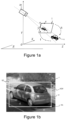
- FIG. 1a illustrates a vehicle V in a real environment of a shooting device 20 and on a selected image i taken by said shooting device 20.
- a real environment is a subset of the real three-dimensional world in which vehicles travel on a traffic lane.
- the shooting device 20 is able to take images of vehicles traveling or stationary on a traffic lane.
- the camera device 20 is mounted fixed relative to said traffic lane.
- the shooting device 20 is a highway radar located on a road including the traffic lane, capable of detecting speed violations of the vehicle V.
- the shooting device 20 is a traffic light radar located at an intersection with another traffic lane, capable of detecting violations of crossing said traffic light while the traffic light indicates a mandatory stop (for example by a red color).
- the shooting device 20 is capable of taking a sequence of images over time, in particular a video, the selected image i being an image selected in the sequence of images.
- the selected image i is selected for example to rule on a speeding offense or crossing a traffic light.
- the camera device 20 is arranged at a height relative to the traffic lane.
- the real environment of the shooting device 20 is identified by a three-dimensional terrestrial reference frame whose origin O is advantageously a point located in a general plane P including the traffic lane.
- the origin O of the terrestrial reference frame is located on a virtual infraction line representing the location of a measurement carried out by a control unit associated with the shooting device, for example a speed measurement or a measurement of crossing a traffic light.
- the axes of the terrestrial reference frame include an axis OY oriented upwards (towards the sky), and two axes OX, OZ located in the general plane P.
- a point in the real environment is called a real point and has coordinates (Xi, Yi,Zi) in the terrestrial frame of reference.
- the selected image i is a two-dimensional representation of the real environment in the field of vision of the shooting device 20.
- a two-dimensional image marker is defined.
- the image marker has for example a point o located at the top left of the selected image i and includes two axes of horizontal abscissa ox and vertical oy.
- a point in the selected image i is called an image point and has coordinates (xi,yi) in the image frame.
- the shooting device 20 is characterized by known or determined parameters including for example a transverse inclination angle, a focal length and a height. From these parameters, those skilled in the art know how to define a mathematical function f making it possible to determine an image point in the image i from a real point in the real environment. Likewise, those skilled in the art know how to define an inverse mathematical function fi making it possible to determine a real point from an image point and an affine plane containing said real point.
- the mathematical function f makes it possible to calculate the coordinates (xi,yi) of an image point from the coordinates of a real point (Xi,Yi,Zi).
- the inverse mathematical function fi makes it possible to calculate the coordinates of a real point (Xi,Yi,Zi) from the coordinates (xi,yi) of an image point and an affine plane comprising said real point.
- the affine plane is the general plane P.
- a vehicle V modeled by a parallelepiped of predetermined height includes at its base real points located in an affine plane which coincides with the general plane P, and on the face opposite to its base, real points located in a plane parallel to the general plane P and located at the predetermined distance from said general plane P.
- the calculator can be integrated into a shooting device 20.
- the computer can be remote and capable of processing images a posteriori, for example as part of a subsequent analysis of a detected offense.
- the calculator has the mathematical function f making it possible to determine an image point from a real point and the inverse mathematical function fi making it possible to determine a real point from an image point and an affine plane containing said point real, a real point in the real environment of the shooting device 20 having as image an image point in the selected image i.
- the calculator is able to determine a bounding box from a selected image i taken by a shooting device 20 according to a first algorithm or according to a second algorithm.
- the computer makes the approximation that the orientation of the vehicle V is that of the orientation of the vehicle's lane.
- the first algorithm is ideal when the selected image i does not include an intersection with another traffic lane.
- the first algorithm is applicable for example for a shooting device 20 being a speed radar on a high-speed traffic lane, for example a motorway.
- the first algorithm is applicable for example for a shooting device 20 being a traffic light radar located at an intersection, if the vehicle is positioned on a portion of the road located upstream of the traffic light according to the direction of traffic of the traffic lane. Indeed, on the upstream portion of the road, it is possible to approximate that the orientation of the vehicle V is substantially the same as the orientation of the traffic lane.
- the calculator determines the bounding box according to the second algorithm advantageously using results from the first algorithm on images prior in time.
- FIG. 1b illustrates a selected image i taken by the shooting device 20 and comprising a vehicle V circulating on a traffic lane 10 defining the general plane P.
- the vehicle V is modeled by a rectangular box b2d generated by any technique known to the state of the art.
- the rectangular box b2d is for example defined in image i by a first point K1 and a second point K2.
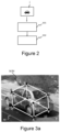
- FIG. 2 illustrates the steps of the method for determining the invention according to the first algorithm.
- the determination method of the invention comprises a first determination step 101, a second determination step 102.
- the calculator determines from the selected image i, an intermediate bounding box bi3d.
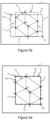
- FIG. 3a illustrates an intermediate bi3d bounding box in the real environment including vehicle V.
- the intermediate bi3d bounding box is associated with a vehicle template selected from a library.
- a vehicle template comprises a triplet of dimensions (L,w,h) including a length L, a width w and a height h, for example in centimeters.
- the library includes a motorcycle template, a city car template, and a truck template.
- the library includes several motorcycle templates, several car templates, and several truck templates.
- the library includes a single city car template.
- the intermediate bounding box bi3d is an intermediate parallelepiped ABCDEFGH whose measurements are associated with the triplet of dimensions (L,w,h) of the template.
- the intermediate bounding box bi3d includes a characteristic real point A which is approximated to be located in the general plane P, that is to say on the traffic lane 10.
- the intermediate bounding box bi3d comprises a first face which is the base of the intermediate parallelepiped and whose vertices include, in the conventional trigonometric sense, the characteristic real point A, a second real point B, a fourth real point D and a third real point C. It is approximated that the first face is located in the general plane P.
- the intermediate bounding box bi3d comprises a second face whose vertices include, in the conventional trigonometric sense, a fifth real point E, a sixth real point F, an eighth real point H and a seventh real point G.
- the intermediate bounding box bi3d is advantageously oriented in the same orientation as the traffic lane 10.
- two of the sides of the first face and two of the sides of the second face are parallel to a marking M delimiting the traffic lane 10.
- the calculator works advantageously in the image reference, on the selected image i.
- FIG. 3b also illustrates an intermediate rectangle Ri circumscribed by the projection in the image i by the mathematical function f of the intermediate bounding box bi3d.
- the rectangular box b2d has a first side C1 corresponding to a left side, a second side C2 corresponding to a right side, a third side corresponding to a low side C3, a fourth side corresponding to a high side C4.
- the first point K1 is a vertex located to the right and at the bottom of the rectangular box b2d and which corresponds to the intersection between the third side C3 and the second side C2.
- the second point K2 is a vertex located at the top and to the left of the rectangular box b2d and which corresponds to the intersection between the first side C1 and the fourth side C4.
- a projection P3i in the image i by the mathematical function f of the intermediate bounding box bi3d (and therefore of the intermediate parallelepiped ABCDEFGH) is an intermediate parallelepiped image A'B'C'D'E'F'G'H'.
- the intermediate image parallelepiped A'B'C'D'E'F'G'H' includes the characteristic image point A' which is the projection of the characteristic real point A by said mathematical function f.
- the computer determines the real characteristic point A such characteristic image point A' belongs to the rectangular box b2d.
- the characteristic real point A is determined from the rectangular box b2d and the library by making the approximation that the characteristic real point A is located on a general plane P including the traffic lane of the vehicle V.
- the characteristic real point A is determined so that its location minimizes a loss function involving the intermediate parallelepiped ABCDEFGH and the intermediate bounding box b2d.
- the computer positions the intermediate image parallelepiped A'B'C'D'E'F'G'H' on the selected image i so that the characteristic image point A' is located on the third side of the rectangular box b2d and minimizes the loss function involving the intermediate parallelepiped (in particular its projection P3i in image i) and the intermediate bounding box b2d.
- the first distance d1 is determined between the projection in the image i of the third real point C, called the third image point C', and the first side C1 of the rectangular box b2d.
- the first distance d1 is determined between the projection in the image i of the seventh real point G, called the seventh image point G', and the first side C1 of the rectangular box b2d.
- the second distance d2 is determined between the projection in the image i of the second real point B, called the second image point B', and the second side C2 of the rectangular box b2d.
- the second distance d2 is determined between the projection in the image i of the sixth real point F, called the sixth image point F', and the second side C2 of the rectangular box b2d.
- the orientation of the intermediate bounding box bi3d depends on the orientation of the traffic lane 10.
- the orientation of the intermediate bounding box bi3d is the orientation of the lane, at the location of the vehicle V on said traffic lane.
- the bi3d intermediate bounding box is associated with a template selected from the library. This means that its dimensions are those of the selected template.
- the library includes a single template.
- the selected template is the only template.
- the library includes a plurality of templates.
- the selected template is the one that best matches the b2d rectangular box.
- the calculator treats the library comprising a plurality of templates as a plurality of libraries of a single template, that is to say the calculator determines a plurality of intermediate parallelepipeds associated with the plurality of templates.
- the calculator selects from the plurality of libraries of a single template, the library of a single template minimizing a second loss function involving the projection in the selected image i by the mathematical function f of the intermediate parallelepiped and the box rectangular b2d.
- the calculator thus selects the template minimizing said second loss function, the intermediate parallelepiped associated with the selected template corresponding to the intermediate bounding box bi3d
- the second loss function includes the opposite of the area of the intersection on the area of the union between the intermediate rectangle Ri circumscribed by the projection in the selected image i by the mathematical function f of the parallelepiped intermediate, and the rectangular box b2d.
- intermediate bounding box bi3d and the corresponding intermediate rectangle Ri, as well as the corresponding intermediate parallelepiped ABCDEFGH are qualified as intermediate because they are the result of an intermediate step of the method of the invention and are intended to be modified.
- the vehicle template is associated with a predefined triplet of dimensions (L,w,h) which probably does not correspond to the real dimensions of the vehicle V.
- the intermediate bounding box bi3d which is associated with a vehicle template from the library, is advantageously modified by the computer into a bounding box b3d associated with a final template, by modification of said template vehicle from the library into said final template, without modifying the real characteristic point A, nor consequently the characteristic image point A'.
- the calculator determines the bounding box b3d as a function of the intermediate bounding box bi3d and the rectangular box b2d, without modifying the real characteristic point A, nor consequently the characteristic image point A', the bounding box b3d being associated with a final template .
- the bounding box b3d of the image is determined by modifying the dimensions of the template selected in the library, so as to minimize a gap between a rectangle R circumscribed at the projection in the image i by the mathematical function f of the bounding box b3d and the rectangular box b2d, the characteristic image point A' remaining fixed.
- a modification of the dimensions of the selected template amounts to a modification of the corresponding triplet of dimensions (L,w,h).
- the intermediate bounding box bi3d is an intermediate parallelepiped ABCDEFGH whose measurements are associated with the triplet of dimensions (L,w,h) of the template.
- the rectangle R contains or encompasses the rectangular box b2d so that the third image point C' and the second image point B' are located on the rectangular bounding box b2d, the projection in the image i of the eighth real point H, called the eighth image point H', which may not be located on the rectangular bounding box b2d.
- the rectangular box b2d coincides with the rectangle R circumscribed by a projection P3 in the image selected i by the mathematical function f of the bounding box b3d.
- figure 4b illustrates the bounding box b3d determined in figure 4a , in the real environment including vehicle V.
- the parallelepiped ABCDEFGH and the intermediate parallelepiped ABCDEFGH are referenced with the same points A, B, C, D, E, F, G, H on the figures 3a , 4b , whether they are associated with the intermediate bounding box bi3d or with the bounding box b3d because they correspond to a parallelepiped anchored at the same characteristic real point A, of the same orientation, of which only the dimensions differ.
- the intermediate image parallelepiped A'B'C'D'E'F'G'H' and the image parallelepiped A'B'C'D'E'F'G'H' are referenced with the same points A', B', C', D', E', F', G', H' on the figures 3b, 4a , whether they are associated in the image with the intermediate bounding box bi3d or with the bounding box b3d because they correspond to an image parallelepiped anchored at the same characteristic image point A', of the same orientation, of which only the dimensions differ.
- the final template resulting from the modification of the vehicle template from the library, corresponds much better to the real dimensions of the vehicle V than the template from the library.
- the computer determines the bounding box b3d according to the first algorithm as long as the vehicle is not engaged in the crossing, otherwise, the computer determines the bounding box b3d according to the second algorithm. It is therefore necessary for the computer to locate vehicle V in relation to the intersection.
- the computer advantageously determines a reference point R belonging to the bounding box b3d.
- the reference point R can be located in different locations of the bounding box b3d, provided that the location is fixed for a predetermined vehicle each time the method is implemented.
- the reference point R is the center of the bounding box b3d.
- the reference point R is the center of the first face of the bounding box b3d.
- the reference point R is the midpoint of the edge defined by the third real point C and the fourth real point D.
- the reference point R is the midpoint of the edge defined by the characteristic real point A and the second real point B.
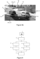
- the selected image i includes a traffic lane 10 of traffic direction S on which the first and second vehicles V1, V2 travel and an intersection 15 with another traffic lane 18 on which the third vehicle V3 enters.
- Crossing 15 includes two traffic lights 13, 14 associated with traffic lane 10.
- intersection 15 is for example delimited by a virtual demarcation line 11.
- the virtual demarcation line 11 advantageously corresponds to an infraction line representing the location of a measurement carried out by a control unit associated with the camera, for example a speed measurement or a measurement of crossing a light of traffic the place where an offense is measured.
- the demarcation line 11 is a line passing through two traffic lights 13, 14 located on either side of the traffic lane 10, as illustrated in the figure 5a .
- the demarcation line 11 is a line perpendicular to the traffic lane and passing at least one traffic light 13, 14.
- the demarcation line 11 is a line perpendicular to the traffic lane and located at a predefined distance from the other traffic lane 18.
- a vehicle V1, V2, V3 is located according to an upstream or downstream positioning of the vehicle V1, V2, V3 with respect to the demarcation line 11, according to the direction of traffic S associated with traffic lane 10.
- the computer uses the first algorithm based on the orientation of the traffic lane 10 and the library as described previously.
- the vehicle When the vehicle V3 is located downstream of the demarcation line 11, the vehicle may no longer be oriented like the traffic lane 10. For example in the case of a change of traffic lane, the vehicle V3 gradually orients itself towards another lane of traffic. In this case, the computer uses the second algorithm to model vehicle V3.
- FIG. 6 illustrates the steps of the method of the invention in a road context comprising crossing with another traffic lane, according to the first algorithm or according to the second algorithm.
- the computer advantageously has a multitude of images taken by the camera device 20, for example from a video.
- the calculator when implementing the method of the invention from a selected image i taken by the shooting device 20 at a given instant of time, the calculator has, except for the first implementation, of a plurality of previous images taken by the shooting device 20 at different times in the time preceding the given time instant, and associated results.
- the qualifier “prior” is added below to the objects determined from a previous image.
- the method of the invention in a road crossing context comprises a prior positioning step 100 and a subsequent recording step 103.
- the computer determines an upstream or downstream positioning of the vehicle V according to the direction of movement S in relation to the demarcation line 11.
- the positioning step 100 allows the computer to know which algorithm to apply.
- the computer detects a front wheel of the vehicle V and determines the upstream or downstream positioning of the vehicle V depending on the position of said wheel relative to the virtual demarcation line 11.
- the calculator determines the positioning of a vehicle V in a selected image i based on an upstream or downstream positioning of a reference point associated with the vehicle V in a previous image.
- the computer determines an orientation of the vehicle V.
- the computer detects in the selected image i an underbody of the vehicle V and determines the orientation of the vehicle V as a function of an orientation of said underbody.
- the computer determines the orientation of the vehicle based on a past trajectory, a steering vector or a speed vector of the vehicle V.
- the calculator determines from the selected image i, the bounding box b3d from the orientation of the vehicle V, a historical template, and the rectangular box b2d.
- the historical template is determined from at least one previous final template.
- a previous final template is a final template associated with the vehicle V and determined for a previous image according to the first and second determination steps 101, 102, that is to say according to the first algorithm.
- the historical template is an average of several previous final templates.
- the historical template is an average of all previous final templates.
- the bounding box b3d includes a characteristic real point A.
- the real characteristic point A is a projection by the inverse mathematical function fi of a characteristic image point A' belonging to the rectangular box b2d and is determined from the rectangular box b2d and the historical template, by making the approximation that the characteristic real point A is located on a general plan P including the travel lane of the vehicle V.
- the historical determination step 112 according to the second algorithm is similar to the first determination step 101 according to the first algorithm, the historical template being used in place of the selected template, the vehicle orientation being used in place of the orientation of the traffic lane.
- the method of the invention comprises the recording step 103.
- the list includes a history of location of the reference point R associated with the vehicle V for each previous image.
- the location of the reference point includes a position in the terrestrial frame of reference.
- the list then makes it possible to determine the past trajectory of the vehicle V and to deduce an orientation of the vehicle V estimated at a given instant of time for a selected image i, for example as a function of a directional vector.
- the directional vector of the vehicle V for a selected image i taken at a given instant of time has for direction a straight line D passing through the previous reference point of most recent temporal data P(t-1) recorded in the list, said last reference point, and passing through a previous reference point from the oldest list P(tN) located at a predetermined distance dp from said last reference point, the predetermined distance dp being between two and four meters.
- Determining a directional vector from a predetermined distance dp rather than a speed vector allows the computer to determine an orientation of the vehicle even in the case where the vehicle V has stopped at the intersection, for example to wait for the change color of a traffic light.
- the location of the reference point includes upstream or downstream positioning.
- the list then makes it possible to determine an upstream or downstream positioning of the vehicle V according to the direction of movement S relative to the demarcation line 11 at a given instant of time for a selected image i.
- the list then makes it possible to determine an upstream or downstream positioning of the vehicle V given according to the direction of movement S relative to the demarcation line 11, depending on an upstream or downstream positioning of a previous reference point.
- the computer determines a downstream positioning of the vehicle V if in the list at least one previous reference point associated with the vehicle V is of downstream positioning. Otherwise, the computer determines an upstream positioning of the vehicle V.
- the computer determines the orientation of the vehicle as shown Figure 7 , as a function of a directional vector whose direction is a straight line D passing through the previous reference point of the most recent temporal data P(t-1) recorded in the list, called the last reference point, and passing through a point reference point from the oldest list P(tN) located at a predetermined distance dp from said last reference point, the predetermined distance dp being between two and four meters.
- the camera 20 films a vehicle V traveling on a lane 10.
- the vehicle V enters the field of vision of the camera 20.
- the vehicle V travels on the lane 10 up to a demarcation line 11 of a crossing 15, then changes direction on the crossing 15 to head towards another traffic lane 18.
- the calculator has images taken by the imaging device 20 at different moments in time from the appearance of the vehicle V in the field of vision of the imaging device 20 until its disappearance from said field of vision.
- the vehicle V On the first selected image i, the vehicle V is detected for the first time by the computer.
- the list associated with vehicle V is empty.
- the list does not include a previous downstream positioning reference point, since it is empty.
- the computer determines an upstream positioning of the vehicle V.
- the calculator determines a bounding box b3d associated with a final template according to the first algorithm.
- the computer determines and records in the list a first reference point R.
- the recording includes a position of the reference point in the terrestrial reference frame, a time corresponding to the given instant of time of the first selected image i and an upstream positioning.
- vehicle V has not yet crossed intersection 15.
- a reference point R is determined and recorded in the list according to recording step 103. All the reference points in the list are upstream positioning.
- the calculator determines for each next selected image a bounding box b3d associated with a final template according to the first algorithm.
- the vehicle's crossing of the intersection is determined at the moment when the determined reference point R is downstream positioning.
- the corresponding selected image i is called the selected crossing image.
- the given instant of time is called the instant of crossing.
- the list does not include a previous downstream positioning reference point according to positioning step 100.
- the computer determines an upstream positioning of the vehicle V.
- the calculator determines a bounding box b3d associated with a final template according to the first algorithm.
- the computer determines and records a new reference point in the list.
- the new reference point is determined for downstream positioning because it is located downstream of the demarcation line 11.
- the list includes a plurality of upstream positioning reference points R and a first downstream positioning reference point corresponding to said new reference point.
- the list includes at least one previous downstream positioning reference point, that determined during the implementation of the method from the selected crossing image.
- the computer therefore determines a downstream positioning of the vehicle V.
- the calculator determines a bounding box b3d associated with a historical template and a vehicle orientation, according to the second algorithm.
- the historical template is for example an average of all the final templates determined from the images selected before the vehicle V has crossed the intersection 15, according to the first algorithm therefore.
- the orientation of the vehicle is determined as a function of a directional vector whose direction is a straight line D passing through the previous reference point of most recent temporal data P(t-1) recorded in the list, called the last reference point , and passing through a previous reference point from the older list P(t-N) located at a distance of for example three meters from said last reference point.
- the calculator determines and records in the list for each selected image i, the associated reference point R to be able to determine an updated directional vector at each implementation of the method of the invention.
Landscapes
- Engineering & Computer Science (AREA)
- Theoretical Computer Science (AREA)
- Physics & Mathematics (AREA)
- General Physics & Mathematics (AREA)
- Computer Vision & Pattern Recognition (AREA)
- Multimedia (AREA)
- Software Systems (AREA)
- Artificial Intelligence (AREA)
- Health & Medical Sciences (AREA)
- Computing Systems (AREA)
- Databases & Information Systems (AREA)
- Evolutionary Computation (AREA)
- General Health & Medical Sciences (AREA)
- Medical Informatics (AREA)
- Traffic Control Systems (AREA)
- Image Analysis (AREA)
- Image Processing (AREA)
Abstract
- une première étape de détermination dans laquelle le calculateur détermine à partir de l'image, une boîte englobante intermédiaire comprenant un point réel caractéristique (A), à partir d'une orientation de la voie de circulation, d'une bibliothèque comprenant au moins un gabarit de véhicule, et de la boîte rectangulaire, la boîte englobante intermédiaire étant associé à un gabarit sélectionné dans la bibliothèque,
- une deuxième étape de détermination dans laquelle le calculateur détermine la boîte englobante (b3d) en fonction de la boîte englobante intermédiaire (bi3d) et de la boîte rectangulaire, sans modifier le point réel caractéristique (A).
Description
- L'invention concerne le domaine de modélisations en trois dimensions d'objets d'intérêts dans des images, en particulier de véhicules dans un contexte routier, les images provenant d'un dispositif de prise de vue fixe dont le champ de vision comprend une voie de circulation.
- Il est connu de l'état de la technique des modélisations en deux dimensions de véhicules dans des images. Un véhicule est modélisé par un rectangle. Ce type de modélisation ne permet pas de déterminer correctement un positionnement d'un véhicule par rapport à une ligne d'infraction ou par rapport à un autre véhicule.
- Il est connu de l'état de la technique d'utiliser des réseaux de neurones pour modéliser un véhicule en trois dimensions, à partir d'une modélisation en deux dimensions dudit véhicule dans des images. Un premier problème est l'entraînement de ces réseaux de neurones. Les images disponibles pour entraîner de tels réseaux de neurones sont en grande majorité des images dont l'angle de vue n'est pas celui d'un dispositif de prise de vue fixe tel qu'un radar routier, mais plutôt des images de caméras embarquées sur des véhicules. Un deuxième problème est le temps de traitement des images qui est trop important.
- L'invention vise à résoudre les problèmes susmentionnés de l'état de la technique en proposant un procédé de détermination d'une boîte englobante modélisant un véhicule en trois dimensions sans utiliser de réseaux de neurones.
- L'invention porte sur un procédé de détermination par un calculateur d'une boîte englobante modélisant un véhicule en trois dimensions, à partir d'une image sélectionnée prise par un dispositif de prise de vue à un instant de temps donné et comprenant ledit véhicule et une voie de circulation, le véhicule étant modélisé dans l'image sélectionnée par une boîte rectangulaire, un point réel dans l'environnement réel du dispositif de prise de vue correspondant à un point image dans l'image sélectionnée, le calculateur disposant d'une fonction mathématique permettant de déterminer un point image à partir d'un point réel et d'une fonction mathématique inverse permettant de déterminer un point réel à partir d'un point image et d'un plan affine contenant ledit point réel, le procédé comprenant les étapes suivantes :
- une première étape de détermination dans laquelle le calculateur détermine à partir de l'image sélectionnée, une boîte englobante intermédiaire comprenant un point réel caractéristique, à partir d'une orientation de la voie de circulation, d'une bibliothèque comprenant au moins un gabarit de véhicule, et de la boîte rectangulaire, la boîte englobante intermédiaire étant associée à un gabarit sélectionné dans la bibliothèque,
- une deuxième étape de détermination dans laquelle le calculateur détermine la boîte englobante en fonction de la boîte englobante intermédiaire et de la boîte rectangulaire, sans modifier le point réel caractéristique, la boîte englobante étant associée à un gabarit final.
- Selon un aspect de l'invention, le point réel caractéristique est une projection par la fonction mathématique inverse d'un point image caractéristique appartenant à la boîte rectangulaire et étant déterminé à partir de la boîte rectangulaire et de la bibliothèque, en faisant l'approximation que le point réel caractéristique est localisé dans un plan général comprenant la voie de circulation du véhicule.
- Selon un aspect de l'invention, le calculateur détermine la boîte englobante en modifiant des dimensions du gabarit sélectionné en un gabarit final, de sorte à minimiser un écart entre un rectangle circonscrit à la projection dans l'image sélectionnée par la fonction mathématique de la boîte englobante et la boîte rectangulaire.
- Selon un aspect de l'invention, la bibliothèque comprend un unique gabarit correspondant au gabarit sélectionné, la boîte englobante intermédiaire est un parallélépipède intermédiaire de dimensions correspondant à des dimensions de l'unique gabarit et comportant une base comprenant le point réel caractéristique, le point réel caractéristique étant déterminé de sorte que sa localisation minimise une fonction de perte faisant intervenir le parallélépipède intermédiaire et la boîte rectangulaire.
- Selon un aspect de l'invention, la bibliothèque comprend une pluralité de gabarits, le calculateur déterminant pour chaque gabarit un parallélépipède intermédiaire de dimensions correspondant à des dimensions dudit gabarit et comportant une base comprenant le point réel caractéristique, le point réel caractéristique étant déterminé de sorte que sa localisation minimise une fonction de perte faisant intervenir le parallélépipède intermédiaire et la boîte rectangulaire, le calculateur sélectionnant le gabarit minimisant une deuxième fonction de perte faisant intervenir la projection dans l'image sélectionnée par la fonction mathématique du parallélépipède intermédiaire, et la boîte rectangulaire, le parallélépipède intermédiaire associé au gabarit sélectionné correspondant à la boîte englobante intermédiaire.
- Selon un aspect de l'invention, le parallélépipède intermédiaire comprend un deuxième point réel et un troisième point réel localisés chacun sur une arrête dudit parallélépipède intermédiaire, la fonction de perte comprenant la somme d'une première distance entre la projection dans l'image sélectionnée par la fonction mathématique du troisième point réel et un premier côté de la boîte rectangulaire, d'une deuxième distance entre la projection dans l'image sélectionnée du deuxième point réel et un deuxième côté de la boîte rectangulaire, et de la différence entre la première distance et la deuxième distance.
- Selon un aspect de l'invention, la deuxième fonction de perte comprend l'opposé de l'aire de l'intersection sur l'aire de l'union entre un rectangle intermédiaire circonscrit à la projection dans l'image sélectionnée par la fonction mathématique du parallélépipède intermédiaire et de la boîte rectangulaire.
- Selon un aspect de l'invention, la voie de circulation est associée à un sens de circulation et comprend un croisement 15 avec une autre voie de circulation 18, le croisement étant délimité par une ligne de démarcation virtuelle, le procédé de détermination comprenant en outre une étape de positionnement préalable dans laquelle le calculateur détermine un positionnement amont ou aval du véhicule selon le sens de circulation par rapport à la ligne de démarcation,
- le procédé de détermination comprenant si le véhicule est de positionnement amont, la première étape de détermination et de la deuxième étape de détermination,
- et comprenant sinon :
- une étape de détermination d'orientation dans laquelle le calculateur détermine une orientation du véhicule,
- une étape de détermination historique dans laquelle le calculateur détermine à partir de l'image sélectionnée, la boîte englobante à partir de l'orientation du véhicule, d'un gabarit historique, et de la boîte rectangulaire, le gabarit historique étant déterminé à partir d'au moins un gabarit final déterminé selon la deuxième étape de détermination à partir d'une image antérieure prise par le dispositif de prise de vue à un instant de temps précédent l'instant de temps donné.
- Selon un aspect de l'invention, le procédé de détermination comprend en outre une étape d'enregistrement dans laquelle le calculateur détermine un point de référence du véhicule à partir de la boîte englobante, enregistre dans une liste un positionnement amont ou aval du point de référence selon le sens de circulation par rapport à la ligne de démarcation, et dans lequel selon l'étape de positionnement, le positionnement du véhicule est déterminé aval si la liste comprend un enregistrement de positionnement aval, le positionnement du véhicule étant déterminé amont sinon.
- Selon un aspect de l'invention, le vecteur directionnel a pour direction une droite passant par le point de référence antérieur de donnée temporelle la plus récente enregistré dans la liste, dit dernier point de référence, et passant par un point de référence antérieur de la liste localisé à une distance prédéterminée dudit dernier point de référence, la distance prédéterminée étant comprise entre deux et quatre mètres.
- L'invention porte également sur un programme d'ordinateur comprenant les instructions de programme mettant en oeuvre les étapes du procédé de détermination, lorsque les instructions de programme sont exécutées par un ordinateur.
- D'autres avantages et caractéristiques de l'invention apparaîtront à la lecture de la description et des dessins.
- La
figure 1a représente un véhicule dans un environnement réel et une image dudit véhicule prise par un dispositif de prise de vue. - La
figure 1b représente une image comprenant un véhicule, le véhicule étant modélisé par une boîte rectangulaire. - La
figure 2 représente les étapes du procédé de l'invention selon un premier algorithme. - La
figure 3a représente une boîte englobante intermédiaire dans un environnement réel en trois dimensions. - La
figure 3b représente une boîte rectangulaire sur une image et une projection dans l'image d'une boîte englobante intermédiaire. - La
figure 4a représente une boîte rectangulaire sur une image et une projection dans l'image d'une boîte englobante. - La
figure 4b représente une boîte englobante dans un environnement réel en trois dimensions. - La
figure 5a représente une image comprenant trois véhicules et trois boîtes rectangulaires associées. - La
figure 5b représente dans un environnement réel trois véhicules et trois boîtes englobantes associées. - La
figure 6 représente les étapes du procédé de l'invention comprenant des étapes de mise en oeuvre selon un deuxième algorithme. - La
figure 7 représente la détermination d'une direction d'un vecteur directionnel d'un véhicule. - L'invention porte sur un procédé de détermination par un calculateur d'une boîte englobante modélisant un véhicule V en trois dimensions, à partir d'une image sélectionnée i prise par un dispositif de prise de vue 20 à un instant de temps donné et comprenant ledit véhicule V et une voie de circulation, le véhicule V étant modélisé dans l'image sélectionnée i par une boîte rectangulaire.
- La
figure 1a illustre un véhicule V dans un environnement réel d'un dispositif de prise de vue 20 et sur une image sélectionnée i prise par ledit dispositif de prise de vue 20. - Un environnement réel est un sous ensemble du monde réel en trois dimensions dans lequel des véhicules circulent sur une voie de circulation.
- Le dispositif de prise de vue 20 est apte à prendre des images de véhicules circulant ou étant à l'arrêt sur une voie de circulation. Le dispositif de prise de vue 20 est monté fixe par rapport à ladite voie de circulation.
- Par exemple, le dispositif de prise de vue 20 est un radar autoroutier localisé sur une route comprenant la voie de circulation, apte à détecter des infractions de vitesse du véhicule V.
- Par exemple, le dispositif de prise de vue 20 est un radar de feu de circulation localisé à un croisement avec une autre voie de circulation, apte à détecter des infractions de franchissement dudit feu de circulation alors que le feu de circulation indique un arrêt obligatoire (par exemple par une couleur rouge).
- Par exemple, le dispositif de prise de vue 20 est apte à prendre une séquence d'images dans le temps, notamment une vidéo, l'image sélectionnée i étant une image sélectionnée dans la séquence d'images.
- L'image sélectionnée i est sélectionnée par exemple pour statuer sur une infraction de vitesse ou de franchissement de feu de circulation.
- Le dispositif de prise de vue 20 est disposé en hauteur par rapport à la voie de circulation. L'environnement réel du dispositif de prise de vue 20 est repéré par un référentiel terrestre tridimensionnel dont l'origine O est avantageusement un point localisé dans un plan général P comprenant la voie de circulation.
- Par exemple, l'origine O du référentiel terrestre est localisé sur une ligne d'infraction virtuelle représentant la localisation d'une mesure effectuée par une unité de contrôle associée au dispositif de prise de vue, par exemple une mesure de vitesse ou une mesure de franchissement d'un feu de circulation.
- Les axes du référentiel terrestre comprennent un axe OY orienté vers le haut (vers le ciel), et deux axes OX, OZ localisés dans le plan général P. Un point dans l'environnement réel est appelé point réel et a pour coordonnées (Xi,Yi,Zi) dans le référentiel terrestre.
- L'image sélectionnée i est une représentation en deux dimensions de l'environnement réel dans le champ de vision du dispositif de prise de vue 20.
- Dans une image sélectionnée i acquise par le dispositif de prise de vue 20, il est défini un repère image bidimensionnel. Le repère image a par exemple pour origine un point o localisé en haut à gauche de l'image sélectionnée i et comprend deux axes d'abscisse ox horizontal et d'ordonnée oy vertical. Un point dans l'image sélectionnée i est appelé point image et a pour coordonnées (xi,yi) dans le repère image.
- Le dispositif de prise de vue 20 est caractérisé par des paramètres connus ou déterminés comprenant par exemple un angle d'inclinaison transverse, une distance focale et une hauteur. A partir de ces paramètres, l'homme du métier sait définir une fonction mathématique f permettant de déterminer un point image dans l'image i à partir d'un point réel de l'environnement réel. De même, l'homme du métier sait définir une fonction mathématique inverse fi permettant de déterminer un point réel à partir d'un point image et d'un plan affine contenant ledit point réel.
- Ainsi, la fonction mathématique f permet de calculer les coordonnées (xi,yi) d'un point image à partir des coordonnées d'un point réel (Xi,Yi,Zi). La fonction mathématique inverse fi permet de calculer les coordonnées d'un point réel (Xi,Yi,Zi) à partir des coordonnées (xi,yi) d'un point image et d'un plan affine comprenant ledit point réel.
- Par exemple, pour des points réels localisés sur la voie de circulation, le plan affine est le plan général P.
- Par exemple, dans l'environnement réel, un véhicule V modélisé par un parallélépipède de hauteur prédéterminée comprend en sa base des points réels localisés dans un plan affine qui est confondu avec le plan général P, et en la face opposée à sa base, des points réels localisés dans un plan parallèle au plan général P et situé à la distance prédéterminée dudit plan général P.
- Le calculateur peut être intégré dans dispositif de prise de vue 20.
- Le calculateur peut être déporté et apte à traiter des images a posteriori, par exemple dans le cadre d'une analyse ultérieure d'une infraction détectée.
- Le calculateur dispose de la fonction mathématique f permettant de déterminer un point image à partir d'un point réel et de la fonction mathématique inverse fi permettant de déterminer un point réel à partir d'un point image et d'un plan affine contenant ledit point réel, un point réel dans l'environnement réel du dispositif de prise de vue 20 ayant pour image un point image dans l'image sélectionnée i.
- Le calculateur est apte à déterminer une boîte englobante à partir d'une image sélectionnée i prise par un dispositif de prise de vue 20 selon un premier algorithme ou selon un deuxième algorithme.
- Selon le premier algorithme, le calculateur fait l'approximation que l'orientation du véhicule V est celle de l'orientation de la voie de circulation du véhicule.
- Le premier algorithme convient parfaitement lorsque l'image sélectionnée i ne comprend pas de croisement avec une autre voie de circulation.
- Le premier algorithme est applicable par exemple pour un dispositif de prise de vue 20 étant un radar de vitesse sur une voie de circulation à grande vitesse, par exemple une autoroute.
- Le premier algorithme est applicable par exemple pour un dispositif de prise de vue 20 étant un radar de feu de circulation localisé à un croisement, si le véhicule est positionné sur une portion de route localisée en amont du feu de circulation selon le sens de circulation de la voie de circulation. En effet, sur la portion de route amont, il est possible de faire l'approximation que l'orientation du véhicule V est sensiblement la même que l'orientation de la voie de circulation.
- Après le passage du feu de circulation, ladite approximation n'est plus possible car le véhicule V est localisé sur le croisement et a la possibilité de s'engager sur une autre voie de circulation. Dans une telle situation, le calculateur détermine la boîte englobante selon le deuxième algorithme en utilisant avantageusement des résultats issus du premier algorithme sur des images antérieures dans le temps.
- La
figure 1b illustre une image sélectionnée i prise par le dispositif de prise de vue 20 et comprenant un véhicule V circulant sur une voie de circulation 10 définissant le plan général P. - Le véhicule V est modélisé par une boîte rectangulaire b2d générée par une technique quelconque connue de l'état de l'art.
- La boîte rectangulaire b2d est par exemple définie dans l'image i par un premier point K1 et un deuxième point K2.
- La
figure 2 illustre les étapes du procédé de détermination de l'invention selon le premier algorithme. - Le procédé de détermination de l'invention comprend une première étape de détermination 101, une deuxième étape de détermination 102.
- Selon la première étape de détermination 101, le calculateur détermine à partir de l'image sélectionnée i, une boîte englobante intermédiaire bi3d.
- Le calculateur détermine la boîte englobante intermédiaire bi3d à partir des données suivantes:
- une orientation de la voie de circulation 10,
- une bibliothèque comprenant au moins un gabarit de véhicule,
- la boîte rectangulaire b2d.
- La
figure 3a illustre une boîte englobante intermédiaire bi3d dans l'environnement réel comprenant le véhicule V. La boîte englobante intermédiaire bi3d est associée à un gabarit de véhicule sélectionné dans une bibliothèque. - Un gabarit de véhicule comprend un triplet de dimensions (L,w,h) comprenant une longueur L, une largeur w et une hauteur h, par exemple en centimètres.
- Par exemple, la bibliothèque comprend un gabarit de moto, un gabarit de voiture citadine et un gabarit de camion.
- Par exemple, la bibliothèque comprend plusieurs gabarits de moto, plusieurs gabarits de voiture et un plusieurs gabarits de camion.
- Par exemple, la bibliothèque comprend un unique gabarit de voiture citadine.
- La boîte englobante intermédiaire bi3d est un parallélépipède intermédiaire ABCDEFGH dont les mesures sont associées au triplet de dimensions (L,w,h) du gabarit.
- La boîte englobante intermédiaire bi3d comprend un point réel caractéristique A dont il est fait approximation qu'il est localisé dans le plan général P, c'est-à-dire sur la voie de circulation 10.
- La boîte englobante intermédiaire bi3d comprend une première face qui est la base du parallélépipède intermédiaire et dont les sommets comprennent, dans le sens trigonométrique conventionnel, le point réel caractéristique A, un deuxième point réel B, un quatrième point réel D et un troisième point réel C. Il est fait approximation que la première face est localisée dans le plan général P.
- Opposée et parallèle à la première face, la boîte englobante intermédiaire bi3d comprend une deuxième face dont les sommets comprennent, dans le sens trigonométrique conventionnel, un cinquième point réel E, un sixième point réel F, un huitième point réel H et un septième point réel G.
- La boîte englobante intermédiaire bi3d comprend quatre arrêtes de dimension la hauteur h du triplet de dimensions (L,w,h) du gabarit, reliant la première face et la deuxième face :
- une première arrête A1 définie par le point réel caractéristique A et le cinquième point réel E,
- une deuxième arrête A2 définie par le deuxième point réel B et le sixième point réel F,
- une troisième arrête A3 définie par le quatrième point réel D et le huitième point réel H,
- une quatrième arrête A4 définie par le troisième point réel C et le septième point réel G.
- La boîte englobante intermédiaire bi3d est avantageusement orientée selon la même orientation que la voie de circulation 10.
- Par exemple, deux des côtés de la première face et deux des côtés de la deuxième face sont parallèles à un marquage M de délimitation de la voie de circulation 10.
- En particulier, il s'agit pour la boîte englobante intermédiaire bi3d, des arrêtes suivantes, dont la dimension correspond à la longueur L du triplet de dimensions (L,w,h) du gabarit :
- l'arrête définie par le point réel caractéristique A et le troisième point réel C,
- l'arrête définie par le deuxième point réel B et le quatrième point réel D,
- l'arrête définie par le cinquième point réel E et le septième point réel G,
- l'arrête définie par le sixième point réel F et le huitième point réel H.
- Les arrêtes de la boîte englobante intermédiaire bi3d qui sont associées à la largeur w du triplet de dimensions (L,w,h) du gabarit sont :
- l'arrête définie par le point réel caractéristique A et le deuxième point réel B,
- l'arrête définie par le troisième point réel C et le quatrième point réel D,
- l'arrête définie par le cinquième point réel E et le sixième point réel F,
- l'arrête définie par le septième point réel G et le huitième point réel H.
- Pour déterminer la boîte englobante intermédiaire bi3d dans l'environnement réel de la
figure 3a , le calculateur travaille avantageusement dans le repère image, sur l'image sélectionnée i. - Sur la
figure 3b , la boîte rectangulaire b2d de l'image i de lafigure 1b est superposée à une projection P3i dans l'image i par la fonction mathématique f de la boîte englobante intermédiaire bi3d. - La
figure 3b illustre également un rectangle intermédiaire Ri circonscrit à la projection dans l'image i par la fonction mathématique f de la boîte englobante intermédiaire bi3d. - La boîte rectangulaire b2d comporte un premier côté C1 correspondant à un côté gauche, un deuxième côté C2 correspondant à un côté droit, un troisième côté correspondant à un côté bas C3, un quatrième côté correspondant à un côté haut C4.
- Le premier point K1 est un sommet localisé à droite et en bas de la boîte rectangulaire b2d et qui correspond à l'intersection entre le troisième côté C3 et le deuxième côté C2.
- Le deuxième point K2 est un sommet localisé en haut et à gauche de la boîte rectangulaire b2d et qui correspond à l'intersection entre le premier côté C1 et le quatrième côté C4.
- Une projection P3i dans l'image i par la fonction mathématique f de la boîte englobante intermédiaire bi3d (et donc du parallélépipède intermédiaire ABCDEFGH) est un parallélépipède intermédiaire image A'B'C'D'E'F'G'H'.
- Le parallélépipède intermédiaire image A'B'C'D'E'F'G'H' comprend le point image caractéristique A' qui est la projection du point réel caractéristique A par ladite fonction mathématique f.
- Pour modéliser au mieux le véhicule V à partir du gabarit de véhicule, le calculateur détermine le point réel caractéristique A telle point image caractéristique A' appartient à la boîte rectangulaire b2d.
- En outre, le point réel caractéristique A est déterminé à partir de la boîte rectangulaire b2d et de la bibliothèque en faisant l'approximation que le point réel caractéristique A est localisé sur un plan général P comprenant la voie de circulation du véhicule V.
- Par exemple, le point réel caractéristique A est déterminé de sorte que sa localisation minimise une fonction de perte faisant intervenir le parallélépipède intermédiaire ABCDEFGH et la boîte englobante intermédiaire b2d.
- Avantageusement, le calculateur positionne le parallélépipède intermédiaire image A'B'C'D'E'F'G'H' sur l'image sélectionnée i de manière à ce que le point image caractéristique A' est localisé sur le troisième côté de la boîte rectangulaire b2d et minimise la fonction de perte faisant intervenir le parallélépipède intermédiaire (en particulier sa projection P3i dans l'image i) et la boîte englobante intermédiaire b2d.
- Par exemple, la fonction de perte comprend une somme de :
- une première distance d1 entre la projection dans l'image sélectionnée i par la fonction mathématique f de la quatrième arrête A4, dite quatrième arrête image A'4, et le premier côté C1 de la boîte rectangulaire b2d,
- une deuxième distance d2 entre la projection dans l'image sélectionnée i par la fonction mathématique f de la deuxième arrête A2, dite deuxième arrête image A'2, et le deuxième côté C2 de la boîte rectangulaire b2d,
- une différence entre la première distance d1 et la deuxième distance d2, en particulier la valeur absolue de cette différence.
- Par exemple, la première distance d1 est déterminée entre la projection dans l'image i du troisième point réel C, dit troisième point image C', et le premier côté C1 de la boîte rectangulaire b2d.
- Par exemple, la première distance d1 est déterminée entre la projection dans l'image i du septième point réel G, dit septième point image G', et le premier côté C1 de la boîte rectangulaire b2d.
- Par exemple, la deuxième distance d2 est déterminée entre la projection dans l'image i du deuxième point réel B, dit deuxième point image B', et le deuxième côté C2 de la boîte rectangulaire b2d.
- Par exemple, la deuxième distance d2 est déterminée entre la projection dans l'image i du sixième point réel F, dit sixième point image F', et le deuxième côté C2 de la boîte rectangulaire b2d.
- L'orientation de la boîte englobante intermédiaire bi3d est fonction de l'orientation de la voie de circulation 10.
- Par exemple, l'orientation de la boîte englobante intermédiaire bi3d est l'orientation de la voie, en l'emplacement du véhicule V sur ladite voie de circulation.
- La boîte englobante intermédiaire bi3d est associée à un gabarit sélectionné dans la bibliothèque. Cela signifie que ses dimensions sont celles du gabarit sélectionné.
- Par exemple, la bibliothèque comprend un unique gabarit. Le gabarit sélectionné est l'unique gabarit.
- Par exemple, la bibliothèque comprend une pluralité de gabarits. Le gabarit sélectionné est celui qui correspond le mieux à la boîte rectangulaire b2d.
- Pour sélectionner le gabarit qui correspond le mieux, le calculateur traite la bibliothèque comprenant une pluralité de gabarits comme une pluralité de bibliothèques d'un unique gabarit, c'est-à-dire que le calculateur détermine une pluralité parallélépipèdes intermédiaires associée à la pluralité de gabarits.
- Puis, le calculateur sélectionne parmi la pluralité de bibliothèques d'un unique gabarit, la bibliothèque d'un unique gabarit minimisant une deuxième fonction de perte faisant intervenir la projection dans l'image sélectionnée i par la fonction mathématique f du parallélépipède intermédiaire et la boîte rectangulaire b2d.
- Le calculateur sélectionne ainsi le gabarit minimisant ladite deuxième fonction de perte, le parallélépipède intermédiaire associé au gabarit sélectionné correspondant à la boîte englobante intermédiaire bi3d
- Par exemple, la deuxième fonction de perte comprend l'opposé de l'aire de l'intersection sur l'aire de l'union entre le rectangle intermédiaire Ri circonscrit à la projection dans l'image sélectionnée i par la fonction mathématique f du parallélépipède intermédiaire, et de la boîte rectangulaire b2d.
- La
figure 3b illustre un exemple de rectangle intermédiaire Ri. - La boîte englobante intermédiaire bi3d et le rectangle intermédiaire Ri correspondant, ainsi que le parallélépipède intermédiaire ABCDEFGH correspondant sont qualifiés d'intermédiaire parce qu'ils sont le résultat d'une étape intermédiaire du procédé de l'invention et sont destinés à être modifiés.
- En effet, comme illustré sur les
figures 3a et3b , utiliser un gabarit de véhicule issu d'une bibliothèque ne permet souvent pas de déterminer une boîte englobante qui modélise parfaitement le véhicule V. En effet, le gabarit de véhicule est associé à un triplet de dimensions (L,w,h) prédéfini qui ne correspond probablement pas aux dimensions réelles du véhicule V. - Ainsi, selon la deuxième étape de détermination 102, la boîte englobante intermédiaire bi3d, qui est associée à un gabarit de véhicule issu de la bibliothèque, est avantageusement modifiée par le calculateur en une boîte englobante b3d associé à un gabarit final, par modification dudit gabarit de véhicule issu de la bibliothèque en ledit gabarit final, sans modifier le point réel caractéristique A, ni par conséquence le point image caractéristique A'.
- Le calculateur détermine la boîte englobante b3d en fonction de la boîte englobante intermédiaire bi3d et de la boîte rectangulaire b2d, sans modifier le point réel caractéristique A, ni par conséquent le point image caractéristique A', la boîte englobante b3d étant associée à un gabarit final.
- Par exemple, comme illustré sur la
figure 4a , la boîte englobante b3d de l'image est déterminée en modifiant les dimensions du gabarit sélectionné dans la bibliothèque, de sorte à minimiser un écart entre un rectangle R circonscrit à la projection dans l'image i par la fonction mathématique f de la boîte englobante b3d et la boîte rectangulaire b2d, le point image caractéristique A' restant fixe. - Une modification des dimensions du gabarit sélectionné revient à une modification du triplet de dimensions (L,w,h) correspondant.
- La boîte englobante intermédiaire bi3d est un parallélépipède intermédiaire ABCDEFGH dont les mesures sont associées au triplet de dimensions (L,w,h) du gabarit.
- Modifier les dimensions du gabarit revient à modifier le triplet de dimensions (L,w,h) et donc à déplacer par exemple :
- le deuxième point réel B pour que sa projection dans l'image sélectionnée (deuxième point image B') appartienne au deuxième côté C2 de la boîte rectangulaire b2d,
- le troisième point réel C pour que sa projection dans l'image sélectionnée (troisième point image C') appartienne au premier côté C1 de la boîte rectangulaire b2d,
- le huitième point réel H pour que sa projection dans l'image sélectionnée (huitième point image H') appartienne au quatrième côté C4 de la boîte rectangulaire b2d.
- Par exemple, suite à la modification, le rectangle R et la boîte rectangulaire b2d coïncide.
- Par exemple, suite à la modification, le rectangle R contient ou englobe la boîte rectangulaire b2d de sorte que le troisième point image C' et le deuxième point image B' sont localisés sur la boîte englobante rectangulaire b2d, la projection dans l'image i du le point huitième point réel H, dit huitième point image H', pouvant ne pas être localisé sur sur la boîte englobante rectangulaire b2d.
- Sur la
figure 4a , suite à ladite modification, la boîte rectangulaire b2d coïncide avec le rectangle R circonscrit à une projection P3 dans l'image sélectionnée i par la fonction mathématique f de la boîte englobante b3d. - La
figure 4b illustre la boîte englobante b3d déterminée enfigure 4a , dans l'environnement réel comprenant le véhicule V. - Dans un but de simplification des références, le parallélépipède ABCDEFGH et le parallélépipède intermédiaire ABCDEFGH sont référencés avec les mêmes points A, B, C, D, E, F, G, H sur les
figures 3a ,4b , qu'ils soient associés à la boîte englobante intermédiaire bi3d ou à la boîte englobante b3d car ils correspondent à un parallélépipède ancré en le même point réel caractéristique A, de même orientation, dont seules les dimensions diffèrent. - De la même manière, le parallélépipède intermédiaire image A'B'C'D'E'F'G'H' et le parallélépipède image A'B'C'D'E'F'G'H' sont référencés avec les mêmes points A', B', C', D', E', F', G', H' sur les
figures 3b, 4a , qu'ils soient associés dans l'image à la boîte englobante intermédiaire bi3d ou à la boîte englobante b3d car ils correspondent à un parallélépipède image ancré en le même point image caractéristique A', de même orientation, dont seules les dimensions diffèrent. - Comme illustré sur la
figure 4b au travers de la boîte englobante b3d, le gabarit final, issu de la modification du gabarit de véhicule de la bibliothèque, correspond beaucoup mieux aux dimensions réelles du véhicule V que le gabarit issu de la bibliothèque. - Dans un contexte routier de croisement, le calculateur détermine la boîte englobante b3d selon le premier algorithme tant que le véhicule n'est pas engagé dans le croisement, sinon, le calculateur détermine la boîte englobante b3d selon le deuxième algorithme. Il est donc nécessaire pour le calculateur de localiser le véhicule V par rapport au croisement.
- Pour localiser le véhicule V par rapport à un croisement, le calculateur détermine avantageusement un point de référence R appartenant à la boîte englobante b3d.
- Le point de référence R peut être localisé en différents endroits de la boîte englobante b3d, pourvu que la localisation soit fixe pour un véhicule prédéterminé à chaque mise en ouvres du procédé.
- Par exemple, le point de référence R est le centre de la boîte englobante b3d.
- Par exemple, comme illustré sur la
figure 4b , le point de référence R est le centre de la première face de la boîte englobante b3d. - Par exemple, le point de référence R est le milieu de l'arrête définie par le troisième point réel C et le quatrième point réel D.
- Par exemple, le point de référence R est le milieu de l'arrête définie par le point réel caractéristique A et le deuxième point réel B.
- La
figure 5a représente une image sélectionnée i comprenant : - un premier véhicule V1 modélisé par une première boîte rectangulaire b2d_V1,
- un deuxième véhicule V2 modélisé par une deuxième boîte rectangulaire b2d_V2,
- un troisième véhicule V3 modélisé par une troisième boîte rectangulaire b2d_V3.
- L'image sélectionnée i comprend une voie de circulation 10 de sens de circulation S sur laquelle circulent les premier et deuxième véhicules V1, V2 et un croisement 15 avec une autre voie de circulation 18 sur laquelle s'engage le troisième véhicule V3.
- Le croisement 15 comprend deux feux de circulation 13, 14 associés à la voie de circulation 10.
- Pour localiser le véhicule V1, V2, V3 par rapport à un croisement 15, le croisement 15 est par exemple délimité par une ligne de démarcation 11 virtuelle.
- La ligne de démarcation virtuelle 11 correspond avantageusement à une ligne d'infraction représentant la localisation d'une mesure effectuée par une unité de contrôle associée au dispositif de prise de vue, par exemple une mesure de vitesse ou une mesure de franchissement d'un feu de circulation l'endroit en lequel est mesurée une infraction.
- Par exemple la ligne de démarcation 11 est une ligne passant par deux feux de circulation 13, 14 localisés de part et d'autre de la voie de circulation 10, comme illustré sur la
figure 5a . - Par exemple la ligne de démarcation 11 est une ligne perpendiculaire à la voie de circulation et passant au moins un feu de circulation 13, 14.
- Par exemple la ligne de démarcation 11 est une ligne perpendiculaire à la voie de circulation et localisée à une distance prédéfinie de l'autre voie de circulation 18.
- Pour localiser le véhicule V1, V2, V3 par rapport à la ligne de démarcation 11 virtuelle, un véhicule V1, V2, V3 est localisé selon un positionnement amont ou aval du véhicule V1, V2, V3 par rapport à la ligne de démarcation 11, selon le sens de circulation S associé à la voie de circulation 10.
- Pour modéliser avec une boîte englobante b3d un véhicule V1, V2 localisé en amont de la ligne de démarcation 11, le calculateur utilise le premier algorithme basé sur l'orientation de la voie de circulation 10 et la bibliothèque telle que décrit précédemment.
- Lorsque le véhicule V3 est localisé en aval de la ligne de démarcation 11, le véhicule peut ne plus être orienté comme la voie de circulation 10. Par exemple dans le cas d'un changement de voie de circulation, le véhicule V3 s'oriente progressivement en direction d'une autre voie de circulation. Dans ce cas, le calculateur utilise le deuxième algorithme pour modéliser le véhicule V3.
- La
figure 5b illustre dans l'environnement réel les trois véhicules de lafigure 5a modélisés par trois boîtes englobantes : - une première boîte englobante b3d_V1 associée au premier véhicule V1,
- une deuxième boîte englobante b3d_V2 associée au deuxième véhicule V2,
- une troisième boîte englobante b3d_V3 associée au troisième véhicule V3,
- La
figure 6 illustre les étapes du procédé de l'invention dans un contexte routier comprenant croisement avec une autre voie de circulation, selon le premier algorithme ou selon le deuxième algorithme. - Dans un contexte routier de croisement, le calculateur dispose avantageusement d'une multitude d'images prise par le dispositif de prise de vue 20, par exemple issues d'une vidéo.
- Ainsi, lors de la mise en oeuvre du procédé de l'invention à partir d'une image sélectionnée i prise par le dispositif de prise de vue 20 à un instant de temps donné, le calculateur dispose, sauf à la première mise en oeuvre, d'une pluralité d'images antérieures prises par le dispositif de prise de vue 20 à différents instants dans le temps précédent l'instant de temps donné, et des résultats associés.
- Pour une meilleure distinction de ce qui est relatif aux images antérieures et à l'image sélectionnée i, le qualificatif « antérieur » est ajouté ci-après aux objets déterminés à partir d'une image antérieure.
- En plus des étapes pour déterminer la boîte englobante b3d en relation avec le premier et le deuxième algorithme, le procédé de l'invention dans un contexte routier de croisement, comprend une étape de positionnement 100 préalable et une étape d'enregistrement 103 postérieure.
- Selon l'étape de positionnement 100, le calculateur détermine un positionnement amont ou aval du véhicule V selon le sens de circulation S par rapport à la ligne de démarcation 11.
- L'étape de positionnement 100 permet au calculateur de savoir quel algorithme appliquer.
- Par exemple, le calculateur, détecte une roue avant du véhicule V et détermine le positionnement amont ou aval du véhicule V en fonction de la position de ladite roue par rapport à la ligne de démarcation virtuelle 11.
- Par exemple, le calculateur détermine le positionnement d'un véhicule V dans une image sélectionnée i en fonction d'un positionnement amont ou aval d'un point de référence associé au véhicule V dans une image antérieure.
- Pour déterminer la boîte englobante b3d, le procédé de détermination comprend les étapes suivantes :
- si le véhicule V est de positionnement amont : la première étape de détermination 101 et de la deuxième étape de détermination 102, selon premier algorithme,
- si le véhicule V est de positionnement aval : une étape de détermination d'orientation 111 et une étape de détermination historique 112, selon le deuxième algorithme.
- Selon l'étape de détermination d'orientation 111, le calculateur détermine une orientation du véhicule V.
- Par exemple, le calculateur, détecte dans l'image sélectionnée i un bas de caisse du véhicule V et détermine l'orientation du véhicule V en fonction d'une orientation dudit bas de caisse.
- Par exemple, le calculateur détermine l'orientation du véhicule en fonction d'une trajectoire passée, d'un vecteur directeur ou d'un vecteur vitesse du véhicule V.
- Selon l'étape de détermination historique 112, le calculateur détermine à partir de l'image sélectionnée i, la boîte englobante b3d à partir de l'orientation du véhicule V, d'un gabarit historique, et de la boîte rectangulaire b2d.
- Le gabarit historique est déterminé à partir d'au moins un gabarit final antérieur.
- Un gabarit final antérieur est un gabarit final associé au véhicule V et déterminé pour une image antérieure selon les première et deuxième étapes de détermination 101, 102, c'est-à-dire selon le premier algorithme.
- Par exemple, le gabarit historique est une moyenne de plusieurs gabarits finaux antérieurs.
- Par exemple, le gabarit historique est une moyenne de tous les gabarits finaux antérieurs.
- Comme pour le premier algorithme, la boîte englobante b3d comprend un point réel caractéristique A.
- Le point réel caractéristique A est une projection par la fonction mathématique inverse fi d'un point image caractéristique A' appartenant à la boîte rectangulaire b2d et est déterminé à partir de la boîte rectangulaire b2d et du gabarit historique, en faisant l'approximation que le point réel caractéristique A est localisé sur un plan général P comprenant la voie de circulation du véhicule V.
- Ainsi, l'étape de détermination historique 112 selon le deuxième algorithme est similaire à la première étape de détermination 101 selon le premier algorithme, le gabarit historique étant utilisé à la place du gabarit sélectionné, l'orientation de véhicule étant utilisée à la place de l'orientation de la voie de circulation.
- Ce qui a été décrit précédemment en relation avec première étape de détermination 101 est ainsi transposable l'étape de détermination historique 112.
- Suite à la détermination de la boîte englobante b3d selon le premier algorithme ou le deuxième algorithme, le procédé de l'invention comprend l'étape d'enregistrement 103.
- L'étape d'enregistrement 103 comprend :
- la détermination d'un point de référence R du véhicule V à partir de la boîte englobante b3d, comme illustré et décrit en relation avec la
figure 4b , - la détermination d'un positionnement amont ou aval du point de référence R par rapport à la ligne de démarcation 11 et selon le sens de circulation S,
- l'enregistrement dans une liste d'une localisation du point de référence R, de préférence en association avec une donnée temporelle associée l'instant de temps donné de la prise de vue de l'image sélectionnée i.
- Suite à une mise en oeuvre du procédé de l'invention par le calculateur pour une pluralité d'images antérieures, la liste comprend un historique de localisation du point de référence R associé au véhicule V pour chaque image antérieure.
- Par exemple, la localisation du point de référence comprend une position dans le référentiel terrestre. La liste permet alors de déterminer la trajectoire passée du véhicule V et d'en déduire une orientation du véhicule V estimée à un instant de temps donné pour une image sélectionnée i, par exemple en fonction d'un vecteur directionnel.
- Par exemple, comme représenté sur la
figure 7 , le vecteur directionnel du véhicule V pour une image sélectionnée i prise à un instant de temps donné, a pour direction une droite D passant par le point de référence antérieur de donnée temporelle la plus récente P(t-1) enregistré dans la liste, dit dernier point de référence, et passant par un point de référence antérieur de la liste plus ancien P(t-N) localisé à une distance prédéterminée dp dudit dernier point de référence, la distance prédéterminée dp étant comprise entre deux et quatre mètres. - Déterminer un vecteur directionnel à partir d'une distance prédéterminée dp plutôt qu'un vecteur vitesse permet au calculateur de déterminer une orientation du véhicule même dans le cas où le véhicule V s'est arrêté au niveau du croisement, par exemple pour attendre le changement de couleur d'un feu de circulation.
- On remarque sur la
figure 7 qu'avant la ligne de démarcation 11 virtuelle, les points de référence antérieurs sont alignés et qu'après la ligne de démarcation 11 virtuelle, les points de référence antérieurs suivent une ligne courbe, le véhicule effectuant un changement de voie de circulation. - Par exemple, la localisation du point de référence comprend un positionnement amont ou aval. La liste permet alors de déterminer un positionnement amont ou aval du véhicule V selon le sens de circulation S par rapport à la ligne de démarcation 11 à un instant de temps donné pour une image sélectionnée i.
- La liste permet alors de déterminer un positionnement amont ou aval du véhicule V donné selon le sens de circulation S par rapport à la ligne de démarcation 11, en fonction d'un positionnement amont ou aval d'un point de référence antérieur.
- Un exemple d'utilisation de la liste issue de l'étape d'enregistrement 103 est donné ci-dessous.
- Selon l'étape de positionnement 100, le calculateur détermine un positionnement aval du véhicule V si dans la liste au moins un point de référence antérieur associé au véhicule V est de positionnement aval. Sinon, le calculateur détermine un positionnement amont du véhicule V.
- Selon l'étape de détermination d'orientation 111, le calculateur détermine l'orientation du véhicule tel que représenté
figure 7 , en fonction d'un vecteur directionnel dont la direction est une droite D passant par le point de référence antérieur de donnée temporelle la plus récente P(t-1) enregistré dans la liste, dit dernier point de référence, et passant par un point de référence antérieur de la liste plus ancien P(t-N) localisé à une distance prédéterminée dp dudit dernier point de référence, la distance prédéterminée dp étant comprise entre deux et quatre mètres. - Une illustration est faite ci-après selon le scénario suivant. Le dispositif de prise de vue 20 filme un véhicule V circulant sur une voie de circulation 10. Le véhicule V entre dans le champ de vision du dispositif de prise de vue 20. Le véhicule V circule sur la voie de circulation 10 jusqu'à une ligne de démarcation 11 d'un croisement 15, puis change de direction sur le croisement 15 pour se diriger vers une autre voie de circulation 18.
- Le calculateur dispose d'images prises par le dispositif de prise de vue 20 à différents instants dans le temps depuis l'apparition du véhicule V dans le champ de vision du dispositif de prise de vus 20 jusqu'à sa disparition dudit champ de vision.
- Sur la première image sélectionnée i, le véhicule V est détecté pour la première fois par le calculateur. La liste associée au véhicule V est vide.
- Selon l'étape de positionnement 100, la liste ne comprend pas un point de référence antérieur de positionnement aval, puisqu'elle est vide. Le calculateur détermine un positionnement amont du véhicule V.
- Le calculateur détermine une boîte englobante b3d associée à un gabarit final selon le premier algorithme.
- Selon l'étape d'enregistrement 103, le calculateur détermine et enregistre dans la liste un premier point de référence R. L'enregistrement comprend une position du point de référence dans le référentiel terrestre, une heure correspondant à l'instant de temps donné de la première image sélectionnée i et un positionnement amont.
- Sur les images suivantes sélectionnées, le véhicule V n'a pas encore franchi le croisement 15.
- A chaque mise en oeuvre du procédé de l'invention à partir de ces images suivantes sélectionnées, un point de référence R est déterminé et enregistré dans la liste selon l'étape d'enregistrement 103. Tous les points de référence de la liste sont de positionnement amont.
- Le calculateur détermine pour chaque image suivante sélectionnée une boîte englobante b3d associée à un gabarit final selon le premier algorithme.
- Le franchissement du véhicule du croisement est déterminé au moment où le point de référence R déterminé est de positionnement aval.
- L'image sélectionnée i correspondante est dite image sélectionnée de franchissement. L'instant de temps donné est dit instant de franchissement.
- Pour l'image sélectionnée de franchissement, la liste ne comprend pas un point de référence antérieur de positionnement aval selon l'étape de positionnement 100. Le calculateur détermine un positionnement amont du véhicule V.
- Le calculateur détermine une boîte englobante b3d associée à un gabarit final selon le premier algorithme.
- Selon l'étape d'enregistrement 103, le calculateur détermine et enregistre dans la liste un nouveau point de référence. Le nouveau point de référence est déterminé de positionnement aval car localisé en aval de la ligne de démarcation 11. La liste comprend une pluralité de points de référence R de positionnement amont et un premier point de référence de positionnement aval correspondant audit nouveau point de référence.
- Sur les images sélectionnées à un instant de temps postérieur à l'instant de franchissement, le véhicule V a franchi le croisement 15.
- Pour ces images sélectionnées, selon l'étape de positionnement 100, la liste comprend au moins un point de référence antérieur de positionnement aval, celui déterminé lors de la mise en oeuvre du procédé à partir de l'image sélectionnée de franchissement. Le calculateur détermine donc un positionnement aval du véhicule V.
- Le calculateur détermine une boîte englobante b3d associée à un gabarit historique et une orientation de véhicule, selon le deuxième algorithme.
- La gabarit historique est par exemple une moyenne de tous les gabarits finaux déterminés à partir des images sélectionnées avant que le véhicule V n'ait franchi le croisement 15, selon le premier algorithme donc.
- L'orientation du véhicule est déterminée en fonction d'un vecteur directionnel dont la direction est une droite D passant par le point de référence antérieur de donnée temporelle la plus récente P(t-1) enregistré dans la liste, dit dernier point de référence, et passant par un point de référence antérieur de la liste plus ancien P(t-N) localisé à une distance de par exemple trois mètres dudit dernier point de référence.
- Selon l'étape d'enregistrement 103, le calculateur détermine et enregistre dans la liste pour chaque image sélectionnée i, le point de référence R associé pour pouvoir déterminer à chaque mise en oeuvre du procédé de l'invention un vecteur directionnel actualisé.
Claims (10)
- Procédé de détermination par un calculateur d'une boîte englobante (b3d) modélisant un véhicule (V) en trois dimensions, à partir d'une image sélectionnée (i) prise par un dispositif de prise de vue (20) à un instant de temps donné et comprenant ledit véhicule (V) et une voie de circulation (10), le véhicule (V) étant modélisé dans l'image sélectionnée (i) par une boîte rectangulaire (b2d), un point réel dans l'environnement réel du dispositif de prise de vue (20) correspondant à un point image dans l'image sélectionnée (i), le calculateur disposant d'une fonction mathématique (f) permettant de déterminer un point image à partir d'un point réel et d'une fonction mathématique inverse (fi) permettant de déterminer un point réel à partir d'un point image et d'un plan affine contenant ledit point réel, le procédé comprenant les étapes suivantes :- une première étape de détermination (101) dans laquelle le calculateur détermine à partir de l'image sélectionnée (i), une boîte englobante intermédiaire (bi3d) comprenant un point réel caractéristique (A), à partir d'une orientation de la voie de circulation, d'une bibliothèque comprenant au moins un gabarit de véhicule, et de la boîte rectangulaire (b2d), la boîte englobante intermédiaire (bi3d) étant associée à un gabarit sélectionné dans la bibliothèque,- une deuxième étape de détermination (102) dans laquelle le calculateur détermine la boîte englobante (b3d) en fonction de la boîte englobante intermédiaire (bi3d) et de la boîte rectangulaire (b2d), sans modifier le point réel caractéristique (A), la boîte englobante (b3d) étant associée à un gabarit final.
- Procédé de détermination selon la revendication précédente, le point réel caractéristique (A) étant une projection par la fonction mathématique inverse (fi) d'un point image caractéristique (A') appartenant à la boîte rectangulaire (b2d) et étant déterminé à partir de la boîte rectangulaire (b2d) et de la bibliothèque, en faisant l'approximation que le point réel caractéristique (A) est localisé dans un plan général (P) comprenant la voie de circulation du véhicule (V).
- Procédé de détermination selon l'une quelconque des revendications 1 à 2, le calculateur déterminant la boîte englobante (b3d) en modifiant des dimensions du gabarit sélectionné en un gabarit final, de sorte à minimiser un écart entre un rectangle (R) circonscrit à la projection dans l'image sélectionnée (i) par la fonction mathématique (f) de la boîte englobante (b3d) et la boîte rectangulaire (b2d).
- Procédé de détermination selon l'une quelconque des revendications précédentes, la bibliothèque comprenant un unique gabarit correspondant au gabarit sélectionné, la boîte englobante intermédiaire (bi3d) étant un parallélépipède intermédiaire de dimensions correspondant à des dimensions de l'unique gabarit et comportant une base comprenant le point réel caractéristique (A), le point réel caractéristique (A) étant déterminé de sorte que sa localisation minimise une fonction de perte faisant intervenir le parallélépipède intermédiaire et la boîte rectangulaire (b2d).
- Procédé de détermination selon l'une quelconque des revendications 1 à 3, la bibliothèque comprenant une pluralité de gabarits, le calculateur déterminant pour chaque gabarit un parallélépipède intermédiaire de dimensions correspondant à des dimensions dudit gabarit et comportant une base comprenant le point réel caractéristique (A), le point réel caractéristique (A) étant déterminé de sorte que sa localisation minimise une fonction de perte faisant intervenir le parallélépipède intermédiaire et la boîte rectangulaire (b2d), le calculateur sélectionnant le gabarit minimisant une deuxième fonction de perte faisant intervenir la projection dans l'image sélectionnée (i) par la fonction mathématique (f) du parallélépipède intermédiaire, et la boîte rectangulaire (b2d), le parallélépipède intermédiaire associé au gabarit sélectionné correspondant à la boîte englobante intermédiaire (bi3d).
- Procédé de détermination selon l'une quelconque des revendications 4 et 5, le parallélépipède intermédiaire comprenant un deuxième point réel (B) et un troisième point réel (C) localisés chacun sur une arrête dudit parallélépipède intermédiaire, la fonction de perte comprenant la somme d'une première distance (d1) entre la projection dans l'image sélectionnée (i) par la fonction mathématique (f) du troisième point réel (C) et un premier côté de la boîte rectangulaire (b2d), d'une deuxième distance (d2) entre la projection dans l'image sélectionnée (i) du deuxième point réel (B) et un deuxième côté de la boîte rectangulaire (b2d), et de la différence entre la première distance (d1) et la deuxième distance (d2).
- Procédé de détermination selon la revendication 6 lorsqu'elle dépend de la revendication 5 ou selon la revendication 5, la deuxième fonction de perte comprenant l'opposé de l'aire de l'intersection sur l'aire de l'union entre un rectangle intermédiaire (Ri) circonscrit à la projection dans l'image sélectionnée (i) par la fonction mathématique (f) du parallélépipède intermédiaire et de la boîte rectangulaire (b2d).
- Procédé de détermination selon l'une quelconque des revendications précédentes, la voie de circulation étant associée à un sens de circulation (S) et comprenant un croisement (15) avec une autre voie de circulation (18), le croisement (15) étant délimité par une ligne de démarcation (11) virtuelle, le procédé de détermination comprenant en outre une étape de positionnement (100) préalable dans laquelle le calculateur détermine un positionnement amont ou aval du véhicule (V) selon le sens de circulation (S) par rapport à la ligne de démarcation (11),le procédé de détermination comprenant, si le véhicule (V) est de positionnement amont, la première étape de détermination (101) et de la deuxième étape de détermination (102),et comprenant sinon :- une étape de détermination d'orientation (111) dans laquelle le calculateur détermine une orientation du véhicule (V),- une étape de détermination historique (112) dans laquelle le calculateur détermine à partir de l'image sélectionnée (i), la boîte englobante (b3d) à partir de l'orientation du véhicule (V), d'un gabarit historique, et de la boîte rectangulaire (b2d), le gabarit historique étant déterminé à partir d'au moins un gabarit final déterminé selon la deuxième étape de détermination (102) à partir d'une image antérieure prise par le dispositif de prise de vue (20) à un instant de temps précédent l'instant de temps donné.
- Procédé de détermination selon la revendication précédente, comprenant en outre une étape d'enregistrement (103) dans laquelle le calculateur détermine un point de référence (R) du véhicule (V) à partir de la boîte englobante (b3d), enregistre dans une liste un positionnement amont ou aval du point de référence (R) selon le sens de circulation (S) par rapport à la ligne de démarcation (11), et dans lequel selon l'étape de positionnement (100), le positionnement du véhicule (V) est déterminé aval si la liste comprend un enregistrement de positionnement aval, le positionnement du véhicule (V) étant déterminé amont sinon.
- Produit programme d'ordinateur comprenant les instructions de programme mettant en oeuvre les étapes du procédé de détermination selon l'une quelconque des revendications 1 à 9, lorsque les instructions de programme sont exécutées par un ordinateur.
Applications Claiming Priority (1)
| Application Number | Priority Date | Filing Date | Title |
|---|---|---|---|
| FR2203474A FR3134644B1 (fr) | 2022-04-14 | 2022-04-14 | Procédé de détermination d’une boîte englobante modélisant un véhicule en trois dimensions |
Publications (1)
| Publication Number | Publication Date |
|---|---|
| EP4261792A1 true EP4261792A1 (fr) | 2023-10-18 |
Family
ID=82100270
Family Applications (1)
| Application Number | Title | Priority Date | Filing Date |
|---|---|---|---|
| EP23166393.1A Pending EP4261792A1 (fr) | 2022-04-14 | 2023-04-03 | Procédé de détermination d'une boîte englobante modélisant un véhicule en trois dimensions |
Country Status (2)
| Country | Link |
|---|---|
| EP (1) | EP4261792A1 (fr) |
| FR (1) | FR3134644B1 (fr) |
Citations (1)
| Publication number | Priority date | Publication date | Assignee | Title |
|---|---|---|---|---|
| US20200219316A1 (en) * | 2019-01-04 | 2020-07-09 | Qualcomm Incorporated | Bounding box estimation and object detection |
-
2022
- 2022-04-14 FR FR2203474A patent/FR3134644B1/fr active Active
-
2023
- 2023-04-03 EP EP23166393.1A patent/EP4261792A1/fr active Pending
Patent Citations (1)
| Publication number | Priority date | Publication date | Assignee | Title |
|---|---|---|---|---|
| US20200219316A1 (en) * | 2019-01-04 | 2020-07-09 | Qualcomm Incorporated | Bounding box estimation and object detection |
Non-Patent Citations (6)
| Title |
|---|
| CHABOT FLORIAN ET AL: "Deep MANTA: A Coarse-to-Fine Many-Task Network for Joint 2D and 3D Vehicle Analysis from Monocular Image", 2017 IEEE CONFERENCE ON COMPUTER VISION AND PATTERN RECOGNITION (CVPR), IEEE COMPUTER SOCIETY, US, 21 July 2017 (2017-07-21), pages 1827 - 1836, XP033249524, ISSN: 1063-6919, [retrieved on 20171106], DOI: 10.1109/CVPR.2017.198 * |
| JEONG-KYUN LEE ET AL: "1-Point RANSAC-Based Method for Ground Object Pose Estimation", ARXIV.ORG, CORNELL UNIVERSITY LIBRARY, 201 OLIN LIBRARY CORNELL UNIVERSITY ITHACA, NY 14853, 9 August 2020 (2020-08-09), XP081737317 * |
| JIAOJIAO FANG ET AL: "3D Bounding Box Estimation for Autonomous Vehicles by Cascaded Geometric Constraints and Depurated 2D Detections Using 3D Results", ARXIV.ORG, CORNELL UNIVERSITY LIBRARY, 201 OLIN LIBRARY CORNELL UNIVERSITY ITHACA, NY 14853, 1 September 2019 (2019-09-01), XP081473552 * |
| LU DUO ET AL: "CAROM - Vehicle Localization and Traffic Scene Reconstruction from Monocular Cameras on Road Infrastructures", 2021 IEEE INTERNATIONAL CONFERENCE ON ROBOTICS AND AUTOMATION (ICRA), IEEE, 30 May 2021 (2021-05-30), pages 11725 - 11731, XP033989141, DOI: 10.1109/ICRA48506.2021.9561190 * |
| MOUSAVIAN ARSALAN ET AL: "3D Bounding Box Estimation Using Deep Learning and Geometry", 2017 IEEE CONFERENCE ON COMPUTER VISION AND PATTERN RECOGNITION (CVPR), IEEE COMPUTER SOCIETY, US, 21 July 2017 (2017-07-21), pages 5632 - 5640, XP033249923, ISSN: 1063-6919, [retrieved on 20171106], DOI: 10.1109/CVPR.2017.597 * |
| ZHOU LINGTAO ET AL: "Object Viewpoint Classification Based 3D Bounding Box Estimation for Autonomous Vehicles", ARXIV.ORG, CORNELL UNIVERSITY LIBRARY, 201 OLIN LIBRARY CORNELL UNIVERSITY ITHACA, NY 14853, 3 September 2019 (2019-09-03), XP081472307 * |
Also Published As
| Publication number | Publication date |
|---|---|
| FR3134644A1 (fr) | 2023-10-20 |
| FR3134644B1 (fr) | 2024-04-19 |
Similar Documents
| Publication | Publication Date | Title |
|---|---|---|
| CN112507862A (zh) | 基于多任务卷积神经网络的车辆朝向检测方法及系统 | |
| FR3106918A1 (fr) | Procédé et dispositif de reconstruction des voies | |
| EP3679517B1 (fr) | Procede de determination des bords saillants d'une cible sur une image | |
| EP3729327B1 (fr) | Methode de reconnaissance d'objets dans une scene observee en trois dimensions | |
| FR3134644A1 (fr) | Procédé de détermination d’une boîte englobante modélisant un véhicule en trois dimensions | |
| EP4212825B1 (fr) | Procédé d alignement d'une caméra sur une route | |
| CN116682081A (zh) | 高速公路的病害检测方法、装置、电子设备及存储介质 | |
| FR2899363A1 (fr) | Procede et dispositif de detection de mouvement d'objets sur des images d'une scene | |
| Mutharpavalar et al. | Measuring of real-time traffic flow using video from multiple ip-based cameras | |
| FR3106108A1 (fr) | Procédé et dispositif de détermination de trajectoire d’une route | |
| CN119723502B (zh) | 一种基于大模型的车辆虚拟模型生成方法、设备及介质 | |
| FR3168049A1 (fr) | Procédé et dispositif d’apprentissage d’un modèle de prédiction capable de prédire une profondeur associée à différents objets. | |
| FR3162896A1 (fr) | Procédé et dispositif d’apprentissage d’un modèle de prédiction de profondeur associé à un système de vision générant des images pouvant être distordues | |
| FR3166459A1 (fr) | Procédé et dispositif d’apprentissage d’un modèle de restauration d’image pour un système de vision. | |
| FR3163194A1 (fr) | Procédé et dispositif d’apprentissage d’un modèle de prédiction de profondeur à partir de cartes de caractéristiques de différentes résolutions | |
| FR3162895A1 (fr) | Procédé et dispositif d’apprentissage d’un modèle de prédiction de profondeur associé à un système de vision sténopé embarqué dans un véhicule | |
| FR3162894A1 (fr) | Procédé et dispositif de détermination d’une profondeur par un système de vision monoscopique appris par supervision d’un système de vision stéréoscopique | |
| FR3168050A1 (fr) | Procédé et dispositif d’apprentissage de modèles de prédiction de mouvement et de prédiction de profondeur. | |
| FR3167467A1 (fr) | Procédé et dispositif d’apprentissage d’un modèle de prédiction de profondeur capable de traiter des objets dynamiques présents dans une scène. | |
| FR3163480A1 (fr) | Procédé et dispositif de détermination d’une distance séparant un objet d’un véhicule par utilisation de boîte englobante et de modèle local de prédiction de profondeur. | |
| FR3162893A1 (fr) | Procédé et dispositif d’apprentissage d’un modèle de prédiction de profondeur associé à un système de vision multi résolution | |
| WO2024194543A1 (fr) | Procede d'analyse d'un flux video, programme d'ordinateur, dispositif de traitement et vehicule associes | |
| FR3161784A1 (fr) | Procédé et dispositif d’apprentissage d’un modèle de prédiction de profondeur à partir de bandes verticales d’images. | |
| FR3161785A1 (fr) | Procédé et dispositif d’apprentissage d’un modèle de prédiction de profondeur à partir d’images filtrées par bandes verticales. | |
| FR3167233A1 (fr) | Procédé et dispositif d’apprentissage d’un modèle de prédiction de positions de points tridimensionnels associé à un système de vision. |
Legal Events
| Date | Code | Title | Description |
|---|---|---|---|
| PUAI | Public reference made under article 153(3) epc to a published international application that has entered the european phase |
Free format text: ORIGINAL CODE: 0009012 |
|
| STAA | Information on the status of an ep patent application or granted ep patent |
Free format text: STATUS: REQUEST FOR EXAMINATION WAS MADE |
|
| 17P | Request for examination filed |
Effective date: 20230403 |
|
| AK | Designated contracting states |
Kind code of ref document: A1 Designated state(s): AL AT BE BG CH CY CZ DE DK EE ES FI FR GB GR HR HU IE IS IT LI LT LU LV MC ME MK MT NL NO PL PT RO RS SE SI SK SM TR |
|
| RAP1 | Party data changed (applicant data changed or rights of an application transferred) |
Owner name: IDEMIA PUBLIC SECURITY FRANCE |
|
| P01 | Opt-out of the competence of the unified patent court (upc) registered |
Free format text: CASE NUMBER: APP_14771/2025 Effective date: 20250326 |
|
| RAP1 | Party data changed (applicant data changed or rights of an application transferred) |
Owner name: IDEMIA ROAD SAFETY FRANCE |
|
| STAA | Information on the status of an ep patent application or granted ep patent |
Free format text: STATUS: EXAMINATION IS IN PROGRESS |
|
| 17Q | First examination report despatched |
Effective date: 20260130 |