EP4261737A1 - Road occupancy information determination method and apparatus - Google Patents
Road occupancy information determination method and apparatus Download PDFInfo
- Publication number
- EP4261737A1 EP4261737A1 EP21913570.4A EP21913570A EP4261737A1 EP 4261737 A1 EP4261737 A1 EP 4261737A1 EP 21913570 A EP21913570 A EP 21913570A EP 4261737 A1 EP4261737 A1 EP 4261737A1
- Authority
- EP
- European Patent Office
- Prior art keywords
- construction area
- image
- area marker
- road
- lane
- Prior art date
- Legal status (The legal status is an assumption and is not a legal conclusion. Google has not performed a legal analysis and makes no representation as to the accuracy of the status listed.)
- Pending
Links
Images




Classifications
-
- G—PHYSICS
- G06—COMPUTING OR CALCULATING; COUNTING
- G06F—ELECTRIC DIGITAL DATA PROCESSING
- G06F18/00—Pattern recognition
- G06F18/20—Analysing
- G06F18/23—Clustering techniques
- G06F18/232—Non-hierarchical techniques
- G06F18/2321—Non-hierarchical techniques using statistics or function optimisation, e.g. modelling of probability density functions
-
- G—PHYSICS
- G06—COMPUTING OR CALCULATING; COUNTING
- G06V—IMAGE OR VIDEO RECOGNITION OR UNDERSTANDING
- G06V10/00—Arrangements for image or video recognition or understanding
- G06V10/20—Image preprocessing
- G06V10/25—Determination of region of interest [ROI] or a volume of interest [VOI]
-
- G—PHYSICS
- G06—COMPUTING OR CALCULATING; COUNTING
- G06T—IMAGE DATA PROCESSING OR GENERATION, IN GENERAL
- G06T5/00—Image enhancement or restoration
- G06T5/20—Image enhancement or restoration using local operators
- G06T5/30—Erosion or dilatation, e.g. thinning
-
- G—PHYSICS
- G06—COMPUTING OR CALCULATING; COUNTING
- G06T—IMAGE DATA PROCESSING OR GENERATION, IN GENERAL
- G06T5/00—Image enhancement or restoration
- G06T5/70—Denoising; Smoothing
-
- G—PHYSICS
- G06—COMPUTING OR CALCULATING; COUNTING
- G06T—IMAGE DATA PROCESSING OR GENERATION, IN GENERAL
- G06T5/00—Image enhancement or restoration
- G06T5/90—Dynamic range modification of images or parts thereof
- G06T5/94—Dynamic range modification of images or parts thereof based on local image properties, e.g. for local contrast enhancement
-
- G—PHYSICS
- G06—COMPUTING OR CALCULATING; COUNTING
- G06T—IMAGE DATA PROCESSING OR GENERATION, IN GENERAL
- G06T7/00—Image analysis
- G06T7/10—Segmentation; Edge detection
- G06T7/187—Segmentation; Edge detection involving region growing; involving region merging; involving connected component labelling
-
- G—PHYSICS
- G06—COMPUTING OR CALCULATING; COUNTING
- G06T—IMAGE DATA PROCESSING OR GENERATION, IN GENERAL
- G06T7/00—Image analysis
- G06T7/90—Determination of colour characteristics
-
- G—PHYSICS
- G06—COMPUTING OR CALCULATING; COUNTING
- G06V—IMAGE OR VIDEO RECOGNITION OR UNDERSTANDING
- G06V10/00—Arrangements for image or video recognition or understanding
- G06V10/40—Extraction of image or video features
- G06V10/44—Local feature extraction by analysis of parts of the pattern, e.g. by detecting edges, contours, loops, corners, strokes or intersections; Connectivity analysis, e.g. of connected components
- G06V10/457—Local feature extraction by analysis of parts of the pattern, e.g. by detecting edges, contours, loops, corners, strokes or intersections; Connectivity analysis, e.g. of connected components by analysing connectivity, e.g. edge linking, connected component analysis or slices
-
- G—PHYSICS
- G06—COMPUTING OR CALCULATING; COUNTING
- G06V—IMAGE OR VIDEO RECOGNITION OR UNDERSTANDING
- G06V10/00—Arrangements for image or video recognition or understanding
- G06V10/70—Arrangements for image or video recognition or understanding using pattern recognition or machine learning
- G06V10/82—Arrangements for image or video recognition or understanding using pattern recognition or machine learning using neural networks
-
- G—PHYSICS
- G06—COMPUTING OR CALCULATING; COUNTING
- G06V—IMAGE OR VIDEO RECOGNITION OR UNDERSTANDING
- G06V20/00—Scenes; Scene-specific elements
- G06V20/50—Context or environment of the image
- G06V20/56—Context or environment of the image exterior to a vehicle by using sensors mounted on the vehicle
- G06V20/588—Recognition of the road, e.g. of lane markings; Recognition of the vehicle driving pattern in relation to the road
-
- G—PHYSICS
- G06—COMPUTING OR CALCULATING; COUNTING
- G06T—IMAGE DATA PROCESSING OR GENERATION, IN GENERAL
- G06T2207/00—Indexing scheme for image analysis or image enhancement
- G06T2207/20—Special algorithmic details
- G06T2207/20112—Image segmentation details
- G06T2207/20152—Watershed segmentation
-
- G—PHYSICS
- G06—COMPUTING OR CALCULATING; COUNTING
- G06T—IMAGE DATA PROCESSING OR GENERATION, IN GENERAL
- G06T7/00—Image analysis
- G06T7/10—Segmentation; Edge detection
- G06T7/155—Segmentation; Edge detection involving morphological operators
Definitions
- This application relates to the field of computer vision, and in particular, to a method and an apparatus for determining road occupancy information.
- intelligent terminals such as an intelligent transportation device, a smart household device, and a robot are gradually entering people's daily lives. Sensors play a very important role in the intelligent terminals.
- various sensors such as a millimeter wave radar, a lidar, a camera, and an ultrasonic radar, installed on the intelligent terminals sense an ambient environment, collect data, identify and track a moving object, identify a static scenario like a lane line or a signboard, and perform route planning by using a navigator and map data.
- the sensors may sense a risk that may occur and assist in avoidance or even autonomously take necessary avoidance measures, which effectively improves security and comfort of the intelligent terminals.
- a road construction area is an area including a plurality of markers such as a traffic cone, a road rail, a warning sign, a construction vehicle, and an engineering person.
- the road scenario is a main traffic scenario on an urban road, and is also an important factor that affects driving safety of a vehicle.
- functions of adaptive cruise control (adaptive cruise control, ACC) and autonomous emergency braking (autonomous emergency braking, AEB) that are for vehicle control assistance require that the system can sense a road occupancy condition of an obstacle through the sensor and take corresponding obstacle avoidance and vehicle control measures to improve driving safety. Therefore, it is important to identify the construction area including construction area markers through the sensor.
- a rectangular marking frame is mainly used to frame a detected construction area marker to identify the road construction area.
- the rectangular marking frame cannot provide an accurate location of the construction area marker on a road surface.
- a road occupancy condition of the construction area is not accurately evaluated. Therefore, how to accurately identify a construction area marker to determine road occupancy information of a construction area marker is an urgent problem to be resolved.
- This application provides a method and an apparatus for determining road occupancy information, to solve a problem of how to accurately identify a construction area marker to determine road occupancy information of a construction area.
- a method for determining road occupancy information includes: obtaining a first image, and determining a first region of interest ROI based on the first image, where the first ROI includes at least one construction area marker; obtaining a first binary image of the first ROI; performing edge enhancement on the at least one construction area marker that is in the first binary image to obtain a second binary image; obtaining a junction point set of the at least one construction area marker and a road surface based on the second binary image; determining road occupancy information of the at least one construction area marker based on the junction point set of the at least one construction area marker and the road surface; and sending the road occupancy information, where the road occupancy information includes information of a lane on which the at least one construction area marker is located and/or road occupancy range information of a construction area, and the construction area includes the at least one construction area marker.
- accurate location information of the construction area marker is obtained by identifying an edge contour of the at least one construction area marker, to obtain accurate road occupancy information of the accurate construction area marker, which helps an ADAS system formulate a reliable and safe control strategy, to improve driving safety.
- the performing edge enhancement on the at least one construction area marker that is in the first binary image to obtain a second binary image includes: performing a first morphological operation on the first binary image to obtain the first image, and performing a second morphological operation on the first binary image to obtain a second image; performing pixel-wise subtraction between the first image and the second image to obtain a third image; performing independent connected component detection on the first image, the second image, or the first binary image to obtain a fourth image; and performing an operation on the third image and the fourth image by using a label constraint-based watershed algorithm to obtain a fifth image, where the fifth image is the second binary image.
- enhancement detection is performed on an edge of the construction area marker, different types of construction area markers can be detected, and a generalization capability is strong.
- each identified construction area marker has a clear edge without adhesion, so that accuracy of determining the construction area is improved.
- an accurate marker contour may be helpful to determine a junction point between the construction area marker and the road surface.
- the method includes: the first morphological operation includes a dilation operation, and the second morphological operation includes an erosion operation.
- the method includes: the first morphological operation includes a dilation operation of M iterations, and the second morphological operation includes an erosion operation of N iterations, where M and N are positive integers greater than or equal to 1.
- a plurality of iterations are helpful to process more noise in an image, and can segment a construction area marker with an adhesive edge in the image, so that an accuracy rate of subsequent determining of an independent connected unit is improved.
- the first ROI includes: obtaining the first ROI based on a lane width, a lane quantity, a first distance, and a second distance, where a lateral length of the first ROI is determined based on the lane width and the lane quantity, and a longitudinal length of the first ROI is determined based on the first distance and the second distance, the first distance indicates a shortest distance in the first image that is obtained after a camera blind spot is excluded and that is between a lane on which a vehicle is located and the vehicle, and the second distance indicates a longest observable distance in the first image between the lane on which the vehicle is located and the vehicle.
- a detection range of an algorithm can be narrowed, a processing time delay can be reduced, and efficiency of a perception system can be improved.
- the first ROI can be detected through movable target detection or by using a semantic segmentation module, to screen out a movable target in the first ROI.
- the obtaining a first binary image of the first ROI includes: performing a three-channel weighted sum operation based on a color space on the first ROI to obtain a single-channel image of the first ROI, where the color space includes an RGB color space, a YUV color space, or an XYZ color space; and performing binarization on the single-channel image to obtain the first binary image of the first ROI.
- a three-channel weighted sum algorithm based on a color space for obtaining the construction area marker can effectively extract a construction area marker with a plurality of colors, support detection for markers with the plurality of colors in a national standard or a non-national standard due to being insensitive to whether the marker has a strip texture, and have strong generalization.
- the obtaining a junction point set of the at least one construction area marker and a road surface includes: obtaining the junction point set of the at least one construction area marker and the road surface based on a camera calibration parameter and a projection theorem.
- the method includes: clustering, based on a first clustering method, the junction point set of the at least one construction area marker and the road surface to determine different construction areas, where the first clustering method is that a distance between junction point sets that are of the at least one construction area marker and the road surface is less than or equal to a minimum distance threshold.
- a clustered construction area marker separates discontinuous construction areas, and space between different construction areas may be used as available space in a vehicle control strategy, to improve road a rate of utilization.
- the determining road occupancy information of the at least one construction area marker includes: detecting a lane line to obtain location information of the lane line in a vehicle coordinate system; obtaining, based on the junction point set of the at least one construction area marker and the road surface and the location information of the lane line, the information of the lane on which the at least one construction area marker is located; obtaining the road occupancy range information of the construction area based on the junction point set of the at least one construction area marker and the road surface; and determining the road occupancy information of the at least one construction area marker based on the information of the lane on which the at least one construction area marker is located and the road occupancy range information of the construction area.
- a vehicle control module may effectively plan a vehicle driving route based on reported road occupancy information and road occupancy range information of the construction area.
- the reported solution is simpler and more effective.
- the road occupancy range information of the construction area may provide more abundant information for the vehicle control module, so that accuracy of a vehicle control decision is improved.
- the road occupancy information of the at least on construction area marker further includes: track and update the road occupancy information of the at least one construction area marker based on road occupancy information of the at least one construction area marker in a previous frame.
- a clustered construction area may be tracked based on a feature point matching algorithm, or a motion equation may be established, based on a Kalman filter algorithm, for a fitting curve of the junction point set of the construction area marker and the road surface, to track the curve and update a status of the curve.
- an apparatus for determining road occupancy information includes a collection module, a processing module, and a transceiver module, where the collection module is configured to obtain a first image; the processing module is configured to: determine a first region of interest ROI based on the first image, where the first ROI includes at least one construction area marker; obtain a first binary image of the first ROI; perform edge enhancement on the at least one construction area marker that is in the first binary image to obtain a second binary image; obtain a junction point set of the at least one construction area marker and a road surface based on the second binary image; and determine road occupancy information of the at least one construction area marker based on the junction point set of the at least one construction area marker and the road surface; and the transceiver module is configured to send the road occupancy information, where the road occupancy information includes information of a lane on which the at least one construction area marker is located and/or road occupancy range information of a construction area, and the construction area includes the at least one construction area marker.
- accurate location information of the construction area marker is obtained by identifying an edge contour of the at least one construction area marker, to obtain accurate road occupancy information of the accurate construction area marker, which helps an ADAS system formulate a reliable and safe control strategy, to improve driving safety.
- the processing module is further configured to: perform a first morphological operation on the first binary image to obtain a first image, and perform a second morphological operation on the first binary image to obtain a second image; perform pixel-wise subtraction between the first image and the second image to obtain a third image; perform independent connected component detection on the first image, the second image, or the first binary image to obtain a fourth image; and perform an operation on the third image and the fourth image by using a label constraint-based watershed algorithm to obtain a fifth image, where the fifth image is the second binary image.
- enhancement detection is performed on an edge of the construction area marker, different types of construction area markers can be detected, and a generalization capability is strong.
- each identified construction area marker has a clear edge without adhesion, so that accuracy of determining the construction area is improved.
- an accurate marker contour may be helpful to determine a junction point between the construction area marker and the road surface.
- the apparatus includes: the first morphological operation includes a dilation operation, and the second morphological operation includes an erosion operation.
- the apparatus includes: the first morphological operation includes a dilation operation of M iterations, and the second morphological operation includes an erosion operation of N iterations, where M and N are positive integers greater than or equal to 1.
- a plurality of iterations are helpful to process more noise in an image, and can segment a construction area marker with an adhesive edge in the image, so that an accuracy rate of subsequent determining of an independent connected unit is improved.
- the processing module is further configured to: obtain the first ROI based on a lane width, a lane quantity, a first distance, and a second distance, where a lateral length of the first ROI is determined based on the lane width and the lane quantity, a longitudinal length of the first ROI is determined based on the first distance and the second distance, the first distance indicates a shortest distance in the first image that is obtained after a camera blind spot is excluded and that is between a lane on which a vehicle is located and the vehicle, and the second distance indicates a longest observable distance in the first image between the lane on which the vehicle is located and the vehicle.
- a detection range of an algorithm can be narrowed, a processing time delay can be reduced, and efficiency of a perception system can be improved.
- the first ROI can be detected through movable target detection or by using a semantic segmentation module, to screen out a movable target in the first ROI.
- the processing module is further configured to: perform three-channel weighted sum operation based on a color space on the first ROI to obtain a single-channel image of the first ROI, where the color space includes RGB color space, YUV color space, or XYZ color space; and perform binarization on the single-channel image to obtain the first binary image of the first ROI.
- a three-channel weighted sum algorithm based on a color space for obtaining the construction area marker can effectively extract a construction area marker with a plurality of colors, support detection for markers with the plurality of colors in a national standard or a non-national standard due to being insensitive to whether the marker has a strip texture, and have strong generalization.
- the processing module is further configured to: obtain the junction point set of the at least one construction area marker and the road surface based on a camera calibration parameter and a projection theorem.
- the processing module is further configured to: cluster, based on a first clustering method, the junction point set of the at least one construction area marker and the road surface to determine different construction areas, where the first clustering method is that a distance between junction point sets that are of the at least one construction area marker and the road surface is less than or equal to a minimum distance threshold.
- a clustered construction area marker separates discontinuous construction areas, and space between different construction areas may be used as available space in a vehicle control strategy, to improve road a rate of utilization.
- the processing module is further configured to: detect a lane line to obtain location information of the lane line in a vehicle coordinate system; obtain, based on the junction point set of the at least one construction area marker and the road surface and the location information of the lane line, the information of the lane on which the at least one construction area marker is located; obtain the road occupancy range information of the construction area based on the junction point set of the at least one construction area marker and the road surface; and determine the road occupancy information of the at least one construction area marker based on the information of the lane on which the at least one construction area marker is located and the road occupancy range information of the construction area.
- a vehicle control module may effectively plan a vehicle driving route based on reported road occupancy information and road occupancy range information of the construction area.
- the reported solution is simpler and more effective.
- the road occupancy range information of the construction area may provide more abundant information for the vehicle control module, so that accuracy of a vehicle control decision is improved.
- the processing module is further configured to: track and update the road occupancy information of the at least one construction area marker based on road occupancy information of the at least one construction area marker in a previous frame.
- a clustered construction area may be tracked based on a feature point matching algorithm, or a motion equation may be established, based on a Kalman filter algorithm, for a fitting curve of the junction point set of the construction area marker and the road surface, to track the curve and update a status of the curve.
- an apparatus may include a camera, a processor, and a transceiver.
- the processor is configured to invoke a computer program from a memory and run the computer program.
- the processor performs the method according to the first aspect or any one of the possible implementations of the first aspect.
- a computer-readable medium is provided, and is configured to store a computer program.
- the computer program includes instructions for performing the method according to the first aspect or any one of the possible implementations of the first aspect.
- a chip may include a processor and a data interface.
- the processor invokes a computer program from a memory through the data interface and runs the computer program, so that a device in which the chip is installed performs instructions of the method according to the first aspect or any one of the possible implementations of the first aspect.
- a vehicle performs instructions of the method according to the first aspect or any one of the possible implementations of the first aspect.
- FIG. 1 is a schematic diagram of a road construction area that may be applied to an embodiment of this application.
- FIG. 1 may be a front image 100 obtained by a camera on a vehicle.
- the image 100 includes a road construction area including a plurality of markers such as a traffic cone 110, a road rail 120, a warning sign 130, a construction vehicle 140, and/or an engineering person 150.
- a millimeter wave radar Radar
- Sensors used in a current road construction area detection solution include two types: a lidar (Lidar) and a camera (Camera).
- Lidar lidar
- Camera Camera has advantages such as low costs, a small size, easy deployment, and easy maintenance, and is therefore widely applied.
- a method based on a conventional image processing operator For example, a template matching manner is used to search for an area in which the construction area marker in an image is located.
- a method for target identification and detection based on machine learning or deep learning For example, a classifier is designed to classify pixels or areas in an image based on a color or texture feature of the construction area marker, to further determine a construction area.
- the first type of camera-based sensing method mainly focuses on a construction area marker, like a traffic cone and a traffic column, that is located in or around a road and that has a columnar feature like a cone, a cylinder, and a rod. Whether a construction area exists in a current image or video frame is determined by a quantity of construction area markers that are detected through statistics.
- a vehicle controller outputs, based on a determining result, a signal indicating that the vehicle approaches the construction area.
- Disadvantages of such type of method for identifying the construction area marker are as follows: First, a type of the construction area marker that is detected is single, and a detection capability for a non-columnar marker, for example, the road rail 120, is low. Second, whether the construction area exists in the current image or video frame is determined by the quantity of construction area markers that are detected through statistics, which has a risk of false detection. Finally, a lane on which the construction area is located is not marked. Only whether the construction area exists is used as a determining signal of vehicle control, which does not clearly describe how to determine whether the vehicle has left the area.
- the second type of camera-based sensing method mainly trains a convolutional neural network (CNN) for a group of images including the construction area marker, then the convolutional neural network is used to classify and identify such construction area marker, and an identified construction area marker is marked in a form of a two-dimensional marking frame.
- CNN convolutional neural network
- the two-dimensional marking frame may introduce a potential positioning error.
- a CNN-based or machine learning-based method has strong dependence on training data, and the method has a high requirement on a computing capability of a sensing device, like a graphics processing unit GPU and a computing processing unit CPU, and has a high requirement on hardware storage space.
- the method is not suitable for deployment on a platform with low power consumption and a low computing capability.
- the method can only determine a road occupancy condition of the construction area, but cannot determine a range occupied by the construction area in the lane, and cannot provide plenty of assistance in subsequent decision-making of a vehicle control module.
- Another current solution is to mainly detect a yellow, orange, or red construction area marker (including the traffic cone, the traffic column, and the road rail).
- a three-channel RGB image obtained by the camera is processed to obtain two types of images:
- the luminance graph and the orange chart are traversed by using a template matching-based sliding window method, and an area with a bright orange texture is detected; and whether the area includes a stripe is determined based on the classifier, to determine whether the area is a construction area.
- Disadvantages of the method for identifying the construction area marker are as follows: First, only a construction area marker with a yellow, orange, or red color feature is detected, and for a construction area marker with another color, the method does not have a detection capability. In addition, only a construction area marker with a stripe texture is detected, and for a construction area marker with a single color, the method does not have the detection capability. Second, the template matching-based sliding window method is used for a high-resolution image, which has a risk of high processing time delay, and a selected template scale affects accuracy of detection. Finally, this method cannot determine the road occupancy condition of the construction area marker.
- embodiments of this application provide a method and an apparatus for determining road occupancy information of a road construction area.
- FIG. 2 is a schematic flowchart of identifying a road construction area marker according to an embodiment of this application.
- S201 Capture a first image by using a camera on a movable platform, and determine a first region of interest (region of interest, ROI) based on the first image, where the first image is a road picture, and the first ROI indicates an ROI image of a road construction area to-be-detected and includes at least one construction area marker.
- ROI region of interest
- the camera may be installed in front of the movable platform, and is mainly configured to collect a road original picture or a video frame.
- the movable platform may be a vehicle, an uncrewed aerial vehicle, a railway train, a ship, and the like, which is not limited in embodiments of this application.
- the camera may be an around view camera, a monocular camera, a binocular camera, and the like, which is not limited in embodiments of this application.
- S202 Obtain a first binary image of the first ROI in manners of a three-channel weighted sum algorithm based on a color space and binarization.
- the first ROI may be detected through movable target detection or by using a semantic segmentation module, to screen out a movable target in the first ROI.
- the movable target may be a normal pedestrian, a normal vehicle or a normal road rail.
- the normal pedestrian is different from an engineering person, and a difference lies in that the engineering person wears construction clothing.
- the normal vehicle is different from a construction vehicle, and a difference lies in that a color of the construction vehicle is different from a color of the normal vehicle.
- the normal road rail is different from a construction area road rail, and a difference lies in that the normal road rail is located on a lane boundary line and does not belong to a trapezoidal lane area 301, and a color of the construction area road rail is different from a color of the normal road rail.
- the movable target may further be a suspended construction area marker on a shelf of a construction vehicle that is driving normally on a road, which is not limited in these embodiments.
- the movable target detection and semantic segmentation are introduced to constrain the first ROI, so that accuracy of a detection result of the construction area can be further improved.
- a quantity of ROIs of an independent construction area marker is reduced, so that a detection time delay can be effectively reduced, and algorithm efficiency can be improved.
- S203 Perform, based on a label constraint watershed image processing algorithm of a morphological operation, edge enhancement on the at least one construction area marker that is in the first binary image, to obtain a second binary image.
- S204 Obtain a junction point set of the at least one construction area marker and a road surface based on the second binary image.
- S205 Determine road occupancy information of the at least one construction area marker based on the junction point set of the at least one construction area marker and the road surface.
- S206 Send the road occupancy information, where the road occupancy information includes information of a lane on which the at least one construction area marker is located and/or road occupancy range information of a construction area, and the construction area includes the at least one construction area marker.
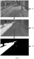
- FIG. 3 is a schematic diagram of obtaining a region of interest of a construction area according to an embodiment of this application.
- FIG. 3 is a specific implementation process of S201.
- a trapezoidal lane area 301 is obtained from an area 307 that is of an original image obtained by the camera or that is framed by a video frame rectangular frame 309, based on a projection theorem and using an offline or online calibration parameter of a camera carried on a movable platform.
- Boundaries of the trapezoidal lane area 301 in a longitudinal direction are a top edge 302 and a bottom edge 303 that respectively correspond to a preset second distance and first distance of an ego vehicle. The second distance indicates a longest observable distance in the first image between a lane on which a vehicle is located and the vehicle.
- the first distance indicates a shortest distance in the first image that is obtained after a camera blind spot is excluded and that is between the lane on which the vehicle is located and the vehicle.
- Boundaries of the trapezoidal lane area 301 in a lateral direction are a waist 304 and a waist 305 that are determined based on a lane width and a lane quantity.
- an internationally specified lane width is 3.5 meters, and the boundaries in the lateral direction of the trapezoidal lane area 301 need to include a range of three lanes which cover a driving direction of the ego vehicle. If the ego vehicle travels in the middle of a middle lane, a value of a left side of the driving direction of the ego vehicle is negative, and a value of a right side of the driving direction is positive, the boundaries in the lateral direction may be set to [-5.25, 5.25] meters. If the ego vehicle drives in the middle of a left lane, the boundaries in the lateral direction may be set to [-1.75, 8.75] meters. If the ego vehicle drives in the middle of a right lane, the boundaries in the lateral direction may be set to [-8.75, 1.75] meters.
- boundary lines of trapezoidal road areas 301 of different road types are also set differently, which are not limited in embodiments of this application.
- the first distance is related to a camera installation location. For example, when the camera is installed on a front windshield of the vehicle, there is an observation blind spot for an image captured by the camera at the head of the vehicle. Therefore, the first distance is greater than a distance from the camera to the head of the vehicle.
- the second distance is related to image resolution, a capability of a detection module, and a longest detection distance required by the vehicle control module.
- the second distance is usually set to be determined by a location of a vanishing point (vanishing point) in the first image.
- the second distance is the longest observable distance between the lane on which the vehicle is located and the vehicle under projection constraint.
- a first ROI 308 framed by an external rectangular frame 306 of the trapezoidal lane area 301 is obtained.
- scaling transformation is performed on the first ROI 308.
- the first ROI 308 may be transformed to resolution of 1280 ⁇ 720 pixels, which is not limited in these embodiments.
- performing scaling transformation on the obtained first ROI 308 is to reduce resolution of an original first ROI 308, and reduce a subsequent calculation amount for identifying the construction area marker.
- a detection range of an algorithm can be narrowed, a processing time delay can be reduced, and efficiency of a perception system can be improved.
- FIG. 4 is a schematic flowchart of obtaining a construction area marker according to an embodiment of this application.
- FIG. 4 is a specific implementation process of step S202.
- a first ROI 401 corresponding to the first ROI 308 in FIG. 3 , is a three-channel image whose resolution is W ⁇ H pixels. It should be understood that, a specific resolution of the first ROI 308 is not limited in embodiments of this application, and is less than or equal to the resolution of the first ROI 401 before compression.
- the color space may be an RGB (or BGR) color space, a YUV color space, or an XYZ color space, which is not limited in these embodiments.
- RGB red
- G green
- B blue
- I 1 c a R ⁇ R + a G ⁇ G + a B ⁇ B
- Weighting coefficients a R , a G , and a B of the three channels in the formula (1) are related to a color of the construction area marker.
- the weighting coefficients of the three channels are determined based on the color of the construction area marker. For example, if the color of construction area marker is red, orange, or yellow, the weighting coefficients a R , a G , and a B in the formula (1) may be set to 0.5, -0.25, and -0.25 respectively.
- the color of the construction area marker is first considered as red, orange, or yellow. If the construction area marker is in another color, for example, blue or green, the single-channel image 402 may be obtained by using a similar coefficient, which is not limited in embodiments of this application.
- the three-channel weighted sum algorithm based on a color space for obtaining the construction area marker can effectively extract a construction area marker with a plurality of colors, support detection for markers with the plurality of colors in a national standard or a non-national standard due to being insensitive to whether the marker has a strip texture, and have strong generalization.
- YUV color space indicates luminance
- U and V indicate chrominance which are used to describe a color and saturation of an image.
- the RGB color space is converted into the YUV color space by using a formula (2-1) or (2-2), pixels are processed, and the three-channel RGB image 401 is compressed into a V-channel image 402, where the formula (2-1) and the formula (2-2) are respectively applicable to digital television coding standards ITU-R BT.601 and BT.709.
- I V 0.615 R ⁇ 0.515 G ⁇ 0.100
- I V 0.615 R ⁇ 0.559 G ⁇ 0.056 B
- a storage manner of the YUV color space has features of small memory space occupation and high data access efficiency, the storage manner may be of a YUV420SP format. As shown in FIG. 8 , the storage manner of the YUV color space is not limited in embodiments of this application.
- the coefficient in the formula (3) may be alternatively determined based on another transformation matrix, for example, opRGB, sRGB, and the like, which is not limited in embodiments of this application.
- the formula (3) is substituted into the formula (1), to obtain a three-channel weighted sum formula (4). Pixels are processed by using the three-channel weighted sum method, and the three-channel image 401 is compressed into the single-channel image 402.
- I 1 c a R t 11 X + t 12 Y + t 13 Z + a G t 21 X + t 22 Y + t 23 Z + a B t 31 X + t 32 Y + t 33 Z
- the RGB (or BGR) color space is a subset of the XYZ color space in this embodiment of this application. Therefore, more color combinations may be described based on the XYZ color space, so that a capability of representing the construction area marker can be improved.
- the method for obtaining the construction area marker by using the three-channel weighted sum based on a color space is applicable to a plurality of color spaces such as RGB, YUV and XYZ, and can adapt to a plurality of images or video frame formats.
- Binarization is performed on the single-channel image 402 by using a formula (5) to obtain a first binary image 403.
- Values corresponding to pixels whose pixel values are between a lower threshold T B and an upper threshold T U are set to 1, which corresponds to a white area of the first binary image 403, that is, an obtained area of the construction area marker.
- Other values of pixels are set to 0, which corresponds to a black area of the first binary image 403, that is, another area except the area of the construction area marker.
- Values of the lower threshold T B and the upper threshold T U of the pixel values are based on a statistical result of the pixel values of the marker area.
- I bin u ⁇ ⁇ 1 , if T B ⁇ I bin u ⁇ ⁇ T U 0 , otherwise
- FIG. 5 is a schematic flowchart of contour detection of a construction area marker according to an embodiment of this application.
- FIG. 5 is a specific implementation process of S203.
- An image 510 corresponding to the first binary image 403 of the construction area marker in FIG. 4 , is a binary image of a construction area marker whose edge contour is to be enhanced.
- a watershed image processing algorithm is a segmentation method of mathematical morphology based on a topology theory.
- the algorithm is very sensitive to noise, and an excessive segmentation condition may occur.
- a label constraint watershed image processing algorithm can avoid segmenting a small noise extreme value area.
- a morphological operation is introduced.
- Basic morphological operations are dilation and erosion.
- a dilation operation is mainly used to combine an area and background points around the area into a whole.
- An erosion operation is mainly used to eliminate edge interference caused by pixel connection in connected areas or adjacent areas.
- the dilation operation and the erosion operation are performed on the first binary image 510, to respectively obtain a first image 520 after the dilation operation and a second image 530 after the erosion operation.
- a convolution kernel K defined in a formula (6) may be used, or a convolution kernel in another form like a convolution kernel that obeys N ⁇ u ⁇ ⁇ ⁇ x 2 ⁇ y 2 Gaussian distribution may be used, which is not limited in embodiments of this application.
- the convolution kernel that obeys the Gaussian distribution can obtain a smoother edge processing effect in image morphological dilation and erosion operations.
- the dilation operation may perform M iterations, and the erosion operation may perform N iterations, where M and N are positive integers greater than or equal to 1.
- the dilation operation performs three iterations, and the erosion operation performs one iteration.
- a specific quantity of iterations is not limited in embodiments of this application.
- a plurality of iterations are helpful to process more noise in an image, and can segment a construction area marker with an adhesive edge in the image, so that an accuracy rate of subsequent determining of an independent connected unit is improved.
- a pixel-wise subtraction operation is performed between the first image 520 obtained after the dilation operation and the second image 530 obtained after the erosion operation, to obtain a third image 540 of a potential edge of the construction area marker.
- Independent connected component detection is performed on the second image 530, and pixels in independent connected units that are different are separately filled by using positive integers of different values, to obtain an image 550 after the connected component detection.
- the independent connected component detection may be further performed on the first binary image 510, to obtain an image 551 after the connected component detection.
- both the image 550 and the image 551 are fourth images after the connected component detection, and both may be used as label constraints for watershed image processing.
- the image 550 or 551 after the connected component detection is combined with the third image 540, and the watershed algorithm is used to fill and enhance the edge of the connected units of the construction area marker, to obtain a fifth image 560 with the enhanced edge of the construction area marker.
- An image 570 is a partially enlarged image of the fifth image 560, and areas with different grayscale values indicate different independent connected areas, or may be understood as different construction area markers.
- enhancement detection is performed on an edge of the construction area marker, different types of construction area markers can be detected, and a generalization capability is strong.
- each identified construction area marker has a clear edge without adhesion, so that accuracy of determining the construction area is improved.
- the method may obtain an accurate marker edge contour, to obtain an accurate junction point between the construction area marker and the road surface, and is particularly applicable to a non-columnar marker like a road rail.
- FIG. 6 is a schematic diagram of a clustering result of a construction area marker according to an embodiment of this application.
- FIG. 6 is a specific implementation process of S204.
- An image 601, corresponding to the fifth image 560 with the enhanced edge of the construction area marker in FIG. 5 is a second binary image with the enhanced edge of the construction area marker.
- a bidirectional six-lane urban road is used as an example.
- a road type is not limited in embodiments of this application.
- the image 601 is a unidirectional three-lane road.
- An area 603, an area 604, and an area 605 respectively indicate a left lane, a middle lane, and a right lane.
- a junction point set of the at least one construction area marker and the road surface is clustered based on a first clustering method, to determine different construction areas.
- the first clustering method is that a distance between junction point sets that are of the at least one construction area marker and the road surface is less than or equal to a minimum distance threshold.
- the construction area includes the at least one construction area marker.
- the distance between the junction point sets that are of the at least one construction area marker and the road surface may be calculated in distance calculation manners such as Euclidean distance, Manhattan distance, Mahalanobis distance, or the like, which is not limited in embodiments of this application.
- the minimum distance threshold is set. If the distance between the junction point sets that are of the at least one construction area marker and the road surface is less than or equal to the minimum distance threshold, adjacent construction area markers are clustered together to belong to a same construction area. In FIG. 6 , there are two clustered construction area markers, which separately are 606 and 607.
- the clustered construction area markers separate discontinuous construction areas, and space between different construction areas may be used as available space in a vehicle control strategy, to improve road a rate of utilization.
- a point at a junction between the construction area marker and the road surface is projected to a vehicle coordinate system by using an offline or online calibration parameter of a camera carried on a movable platform and based on a projection theorem and a ground plane assumption, to obtain an aerial view image 602 of the construction area marker and the lane.
- the distance between the junction point sets that are of the at least one construction area marker and the road surface may be obtained on the aerial view image 602 in distance calculation manners such as the Euclidean distance, the Manhattan distance, the Mahalanobis distance, and the like.
- a marker clustering method based on the aerial view image 602 can make a clustering result of the construction area markers more accurate.
- convex hull points on the enhanced edge of the construction area marker, and a point set formed by these convex hull points is the junction point set of the marker and the road surface.
- FIG. 7 is a schematic flowchart of summarizing and reporting a road occupancy condition of a construction area according to an embodiment of this application.
- FIG. 7 is a specific implementation process of S205.
- S701 Calculate a projection matrix based on a camera calibration parameter and a projection theorem, and project a junction point between a construction area marker and a road surface to a vehicle coordinate system, where the junction point in the vehicle coordinate system is mainly used to estimate a lane and a range that are occupied by the junction point.
- S702 Detect a lane line to obtain location information of the lane line in the vehicle coordinate system, where the location information includes a lane width or lane line equation information.
- the lane width is consistent with the lane width in S201, for example, an internationally specified lane width of 3.5 meters. If the lane line detection function is valid, the lane width in this step is a result of lane line detection, and the lane width obtained by using the result is more accurate.
- S703 Estimate, in a voting manner, based on junction point information of the construction area marker and the location information of the lane line in the vehicle coordinate system, a lane on which the construction area marker is located, where a lane with a large quantity of votes is marked as a lane occupied by a construction area, to obtain information of the lane occupied by the construction area.
- S704 Estimate a boundary location of a point set of the construction area marker based on the junction point information of the construction area marker in the vehicle coordinate system, to obtain a road occupancy range of the construction area.
- the boundary location of the point set of the construction area marker is obtained by estimating shortest and longest distances between these point sets in the vehicle coordinate system and an ego vehicle in lateral and longitudinal directions.
- S705 Determine road occupancy information of the construction area based on the information of the lane occupied by the construction area and the road occupancy range of the construction area.
- the road occupancy information of the construction area may be only the information of the lane occupied by the construction area, the road occupancy range of the construction area, or comprehensive information of the information of the lane occupied by the construction area and the road occupancy range of the construction area, which is not limited in embodiments of this application.
- S706 Send the road occupancy information of the construction area to a vehicle control module.
- the vehicle control module may effectively plan a vehicle driving route based on reported road occupancy information and road occupancy range information of the construction area.
- the reported solution is simpler and more effective.
- the road occupancy range information of the construction area may provide more abundant information for the vehicle control module, so that accuracy of a vehicle control decision is improved.
- S707 Track and update the road occupancy information of the construction area based on a result of a road occupancy condition of the construction area in a previous frame.
- a clustered construction area may be tracked based on a feature point matching algorithm, or a motion equation may be established, based on a Kalman filter algorithm, for a fitting curve of the junction point set of the construction area marker and the road surface, to track the curve and update a status of the curve.
- FIG. 9 is a schematic block diagram of an apparatus for determining road occupancy information according to an embodiment of this application.
- the apparatus for determining the road occupancy information in FIG. 9 may be configured to implement corresponding functions in the embodiments in FIG. 1 to FIG. 8 . To avoid repetition, details are not described again.
- the apparatus for determining road occupancy information in FIG. 9 may include a collection module 901, a processing module 902, and a transceiver module 903.
- the collection module 901 is configured to obtain a first image.
- the processing module 902 is configured to: determine a first region of interest ROI based on the first image, where the first ROI includes at least one construction area marker; obtain a first binary image of the first ROI; perform edge enhancement on the at least one construction area marker that is in the first binary image to obtain a second binary image; obtain a junction point set of the at least one construction area marker and a road surface based on the second binary image; and determine road occupancy information of the at least one construction area marker based on the junction point set of the at least one construction area marker and the road surface.
- the transceiver module 903 is configured to send the road occupancy information, where the road occupancy information includes information of a lane on which the at least one construction area marker is located and/or road occupancy range information of a construction area, and the construction area includes the at least one construction area marker.
- the processing module 902 is further configured to: perform a first morphological operation on the first binary image to obtain a first image, and perform a second morphological operation on the first binary image to obtain a second image; perform pixel-wise subtraction between the first image and the second image to obtain a third image; perform independent connected component detection on the first image, the second image, or the first binary image to obtain a fourth image; and perform an operation on the third image and the fourth image by using a label constraint-based watershed algorithm to obtain a fifth image, where the fifth image is the second binary image.
- the first morphological operation includes a dilation operation
- the second morphological operation includes an erosion operation
- the first morphological operation includes a dilation operation of M iterations
- the second morphological operation includes an erosion operation of N iterations, where M and N are positive integers greater than or equal to 1.
- the processing module 902 is further configured to: obtain the first ROI based on a lane width, a lane quantity, a first distance, and a second distance.
- a lateral length of the first ROI is determined based on the lane width and the lane quantity.
- a longitudinal length of the first ROI is determined based on the first distance and the second distance.
- the first distance indicates a shortest distance in the first image between a lane and a vehicle, and the second distance indicates a longest distance in the first image between the lane and the vehicle.
- the processing module 902 is further configured to: perform a three-channel weighted sum operation based on a color space on the first ROI to obtain a single-channel image of the first ROI; where the color space includes an RGB color space, a YUV color space, or an XYZ color space; and perform binarization on the single-channel image to obtain the first binary image of the first ROI.
- the processing module 902 is further configured to obtain the junction point set of the at least one construction area marker and the road surface based on a calibration parameter of the collection module and a projection theorem.
- the processing module 902 is further configured to cluster, based on a first clustering method, the junction point set of the at least one construction area marker and the road surface to determine different construction areas.
- the first clustering method is that a distance between junction point sets that are of the at least one construction area marker and the road surface is less than or equal to a minimum distance threshold.
- the construction area includes the at least one construction area marker.
- the processing module 902 is further configured to: detect a lane line to obtain location information of the lane line in a vehicle coordinate system; obtain, based on the junction point set of the at least one construction area marker and the road surface and the location information of the lane line, the information of the lane on which the at least one construction area marker is located; obtain the road occupancy range information of the construction area based on the junction point set of the at least one construction area marker and the road surface, where the construction area includes the at least one construction area marker; and determine the road occupancy information of the at least one construction area marker based on the information of the lane on which the at least one construction area marker is located and the road occupancy range information of the construction area.
- the processing module 902 is further configured to: track and update the road occupancy information of the at least one construction area marker based on road occupancy information of the at least one construction area marker in a previous frame.
- the collection module 901 may be a camera 1001 in FIG. 10
- the processing module 902 may be a processor 1002 in FIG. 10
- the transceiver module may be a transceiver 1004 in FIG. 10 . Details are shown in FIG. 10 .
- FIG. 10 is a schematic block diagram of another apparatus for determining road occupancy information according to an embodiment of this application.
- the apparatus for determining road occupancy information in FIG. 10 may include: a camera 1001, a processor 1002, a memory 1003, a transceiver 1004, and a bus 1005.
- the camera 1001, the processor 1002, the memory 1003, and the transceiver 1004 are connected through the bus 1005.
- the memory 1003 is configured to store instructions.
- the processor 1002 is configured to execute the instructions stored in the memory 1003.
- the transceiver is configured to send information.
- the memory 1003 may be coupled to the processor 1002 by using an interface, or integrated with the processor 1002.
- steps in the methods may be implemented by using a hardware integrated logic circuit in the processor 1002, or by using instructions in a form of software.
- the methods disclosed with reference to embodiments of this application may be directly performed by a hardware processor, or may be performed by a combination of hardware in the processor and a software module.
- the software module may be located in a mature storage medium in the art like a random access memory, a flash memory, a read-only memory, a programmable read-only memory, an electrically erasable programmable memory, or a register.
- the storage medium is located in the memory 1003, and the processor 1002 reads information in the memory 1003 and completes the steps in the foregoing methods in combination with hardware of the memory 1003. To avoid repetition, details are not described herein.
- the memory may include a read-only memory and a random access memory, and provides instructions and data to the processor.
- a part of the processor may further include a non-volatile random access memory.
- the processor may further store device type information.
- the apparatus for determining road occupancy information may be a vehicle having a road occupancy information determining function, or may be another component having the road occupancy information determining function.
- the apparatus for determining road occupancy information includes but is not limited to another sensor like an in-vehicle terminal, an in-vehicle controller, an in-vehicle block, an in-vehicle module, an in-vehicle component, an in-vehicle chip, an in-vehicle unit, an in-vehicle radar, or an in-vehicle camera.
- a vehicle may implement the method provided in this application by using the in-vehicle terminal, the in-vehicle controller, the in-vehicle block, the in-vehicle module, the in-vehicle component, the in-vehicle chip, the in-vehicle unit, or the in-vehicle radar or camera.
- the apparatus for determining road occupancy information may be an intelligent terminal having a road occupancy information determining function other than a vehicle, or disposed in an intelligent terminal having a road occupancy information determining function other than a vehicle, or disposed in a component of the intelligent terminal.
- the intelligent terminal may be another terminal device like an intelligent transportation device, a smart household device, or a robot.
- the apparatus for determining road occupancy information includes but is not limited to an intelligent terminal or another sensor like a controller, a chip, a radar, or a camera in the intelligent terminal, and another component.
- the apparatus for determining road occupancy information may be a general-purpose device or a dedicated device. During specific implementation, the apparatus may further be a desktop computer, a portable computer, a network server, a palmtop computer (personal digital assistant, PDA), a mobile phone, a tablet computer, a wireless terminal device, an embedded device, or another device with a processing function.
- PDA personal digital assistant
- a type of the apparatus for determining road occupancy information is not limited in embodiments of this application.
- the apparatus for determining road occupancy information may alternatively be a chip or a processor having a processing function, and the apparatus for determining road occupancy information may include at least one processor.
- the processor may be a single-CPU (single-CPU) processor, or a multi-CPU (multi-CPU) processor.
- the chip or processor with a processing function may be disposed in the sensor, or may not be disposed in the sensor, but is disposed at a receive end of an output signal of the sensor.
- An embodiment of this application further provides a system applied to unmanned driving or intelligent driving.
- the system includes at least one apparatus for determining road occupancy information mentioned in the foregoing embodiment of this application and at least one of other sensors such as a camera and a radar.
- At least one apparatus in the system may be integrated as an entire system or a device, or at least one apparatus in the system may be independently disposed as an element or an apparatus.
- any of the above systems may interact with a central controller of the vehicle to provide detection and/or fusion information for decision or control of driving of the vehicle.
- An embodiment of this application further provides a vehicle.
- the vehicle includes at least one apparatus for determining road occupancy information mentioned in the foregoing embodiment of this application or any one of the foregoing systems.
- sequence numbers of the foregoing processes do not mean execution sequences.
- the execution sequences of the processes should be determined based on functions and internal logic of the processes, and should not constitute any limitation on implementation processes of embodiments of this application.
- the disclosed system, apparatus and method may be implemented in other manners.
- the described apparatus embodiments are merely examples.
- division into the units is merely logical function division and may be other division in actual implementation.
- a plurality of units or components may be combined or integrated into another system, or some features may be ignored or not performed.
- the displayed or discussed mutual couplings or direct couplings or communication connections may be implemented by using some interfaces.
- the indirect couplings or communication connections between the apparatuses or units may be implemented in electronic, mechanical, or other forms.
- the units described as separate parts may or may not be physically separate, and parts displayed as units may or may not be physical units, may be located in one position, or may be distributed on a plurality of network units. Some or all of the units may be selected based on actual requirements to achieve the objectives of the solutions of embodiments.
- the function When the function is implemented in a form of a software functional unit and sold or used as an independent product, the function may be stored in a computer-readable storage medium. Based on such an understanding, the technical solutions in this application essentially, or the part contributing to the conventional technology, or some of the technical solutions may be implemented in a form of a software product.
- the computer software product is stored in a storage medium, and includes several instructions for instructing a computer device (which may be a personal computer, a server, a network device, or the like) to perform all or some of the steps of the methods described in embodiments of this application.
- the foregoing storage medium includes any medium that can store program code, like a USB flash drive, a removable hard disk, a read-only memory (Read-Only Memory, ROM), a random access memory (Random Access Memory, RAM), a magnetic disk, or an optical disc.
- program code like a USB flash drive, a removable hard disk, a read-only memory (Read-Only Memory, ROM), a random access memory (Random Access Memory, RAM), a magnetic disk, or an optical disc.
Landscapes
- Engineering & Computer Science (AREA)
- Theoretical Computer Science (AREA)
- Physics & Mathematics (AREA)
- General Physics & Mathematics (AREA)
- Multimedia (AREA)
- Computer Vision & Pattern Recognition (AREA)
- Data Mining & Analysis (AREA)
- Evolutionary Computation (AREA)
- Artificial Intelligence (AREA)
- General Health & Medical Sciences (AREA)
- Life Sciences & Earth Sciences (AREA)
- Health & Medical Sciences (AREA)
- Medical Informatics (AREA)
- Software Systems (AREA)
- Probability & Statistics with Applications (AREA)
- Computing Systems (AREA)
- Databases & Information Systems (AREA)
- Bioinformatics & Cheminformatics (AREA)
- Bioinformatics & Computational Biology (AREA)
- Evolutionary Biology (AREA)
- General Engineering & Computer Science (AREA)
- Traffic Control Systems (AREA)
- Image Analysis (AREA)
Abstract
Description
- This application claims priority to
Chinese Patent Application No. 202011643276.3, filed with the China National Intellectual Property Administration on December 30, 2020 - This application relates to the field of computer vision, and in particular, to a method and an apparatus for determining road occupancy information.
- With social development, intelligent terminals such as an intelligent transportation device, a smart household device, and a robot are gradually entering people's daily lives. Sensors play a very important role in the intelligent terminals. In a moving process of the intelligent terminals, various sensors, such as a millimeter wave radar, a lidar, a camera, and an ultrasonic radar, installed on the intelligent terminals sense an ambient environment, collect data, identify and track a moving object, identify a static scenario like a lane line or a signboard, and perform route planning by using a navigator and map data. The sensors may sense a risk that may occur and assist in avoidance or even autonomously take necessary avoidance measures, which effectively improves security and comfort of the intelligent terminals.
- A road construction area is an area including a plurality of markers such as a traffic cone, a road rail, a warning sign, a construction vehicle, and an engineering person. The road scenario is a main traffic scenario on an urban road, and is also an important factor that affects driving safety of a vehicle. In an advanced driver assistance system (advanced driver assistance system, ADAS), functions of adaptive cruise control (adaptive cruise control, ACC) and autonomous emergency braking (autonomous emergency braking, AEB) that are for vehicle control assistance require that the system can sense a road occupancy condition of an obstacle through the sensor and take corresponding obstacle avoidance and vehicle control measures to improve driving safety. Therefore, it is important to identify the construction area including construction area markers through the sensor.
- In existing construction area identification, a rectangular marking frame is mainly used to frame a detected construction area marker to identify the road construction area. However, the rectangular marking frame cannot provide an accurate location of the construction area marker on a road surface. As a result, a road occupancy condition of the construction area is not accurately evaluated. Therefore, how to accurately identify a construction area marker to determine road occupancy information of a construction area marker is an urgent problem to be resolved.
- This application provides a method and an apparatus for determining road occupancy information, to solve a problem of how to accurately identify a construction area marker to determine road occupancy information of a construction area.
- According to a first aspect, a method for determining road occupancy information is provided. The method includes: obtaining a first image, and determining a first region of interest ROI based on the first image, where the first ROI includes at least one construction area marker; obtaining a first binary image of the first ROI; performing edge enhancement on the at least one construction area marker that is in the first binary image to obtain a second binary image; obtaining a junction point set of the at least one construction area marker and a road surface based on the second binary image; determining road occupancy information of the at least one construction area marker based on the junction point set of the at least one construction area marker and the road surface; and sending the road occupancy information, where the road occupancy information includes information of a lane on which the at least one construction area marker is located and/or road occupancy range information of a construction area, and the construction area includes the at least one construction area marker.
- In the technical solution in this embodiment of this application, accurate location information of the construction area marker is obtained by identifying an edge contour of the at least one construction area marker, to obtain accurate road occupancy information of the accurate construction area marker, which helps an ADAS system formulate a reliable and safe control strategy, to improve driving safety.
- With reference to the first aspect, in some implementations of the first aspect, the performing edge enhancement on the at least one construction area marker that is in the first binary image to obtain a second binary image includes: performing a first morphological operation on the first binary image to obtain the first image, and performing a second morphological operation on the first binary image to obtain a second image; performing pixel-wise subtraction between the first image and the second image to obtain a third image; performing independent connected component detection on the first image, the second image, or the first binary image to obtain a fourth image; and performing an operation on the third image and the fourth image by using a label constraint-based watershed algorithm to obtain a fifth image, where the fifth image is the second binary image.
- In the technical solution in this embodiment of this application, based on a label constraint watershed image processing algorithm of a morphological operation, enhancement detection is performed on an edge of the construction area marker, different types of construction area markers can be detected, and a generalization capability is strong. In addition, each identified construction area marker has a clear edge without adhesion, so that accuracy of determining the construction area is improved. In addition, an accurate marker contour may be helpful to determine a junction point between the construction area marker and the road surface.
- With reference to the first aspect, in some implementations of the first aspect, the method includes: the first morphological operation includes a dilation operation, and the second morphological operation includes an erosion operation.
- With reference to the first aspect, in some implementations of the first aspect, the method includes: the first morphological operation includes a dilation operation of M iterations, and the second morphological operation includes an erosion operation of N iterations, where M and N are positive integers greater than or equal to 1.
- In the technical solution in this embodiment of this application, a plurality of iterations are helpful to process more noise in an image, and can segment a construction area marker with an adhesive edge in the image, so that an accuracy rate of subsequent determining of an independent connected unit is improved.
- With reference to the first aspect, in some implementations of the first aspect, the first ROI includes: obtaining the first ROI based on a lane width, a lane quantity, a first distance, and a second distance, where a lateral length of the first ROI is determined based on the lane width and the lane quantity, and a longitudinal length of the first ROI is determined based on the first distance and the second distance, the first distance indicates a shortest distance in the first image that is obtained after a camera blind spot is excluded and that is between a lane on which a vehicle is located and the vehicle, and the second distance indicates a longest observable distance in the first image between the lane on which the vehicle is located and the vehicle.
- In the technical solution in this embodiment of this application, based on a method for obtaining the first ROI that is calibrated by a camera and constrained by the lane width, the lane quantity, the first distance, and the second distance, a detection range of an algorithm can be narrowed, a processing time delay can be reduced, and efficiency of a perception system can be improved.
- In some possible implementations, to further improve accuracy of a detection result of the construction area, reduce a detection time delay, and improve algorithm efficiency, the first ROI can be detected through movable target detection or by using a semantic segmentation module, to screen out a movable target in the first ROI.
- With reference to the first aspect, in some implementations of the first aspect, the obtaining a first binary image of the first ROI includes: performing a three-channel weighted sum operation based on a color space on the first ROI to obtain a single-channel image of the first ROI, where the color space includes an RGB color space, a YUV color space, or an XYZ color space; and performing binarization on the single-channel image to obtain the first binary image of the first ROI.
- In the technical solution of this embodiment of this application, a three-channel weighted sum algorithm based on a color space for obtaining the construction area marker can effectively extract a construction area marker with a plurality of colors, support detection for markers with the plurality of colors in a national standard or a non-national standard due to being insensitive to whether the marker has a strip texture, and have strong generalization.
- With reference to the first aspect, in some implementations of the first aspect, the obtaining a junction point set of the at least one construction area marker and a road surface includes: obtaining the junction point set of the at least one construction area marker and the road surface based on a camera calibration parameter and a projection theorem.
- With reference to the first aspect, in some implementations of the first aspect, the method includes: clustering, based on a first clustering method, the junction point set of the at least one construction area marker and the road surface to determine different construction areas, where the first clustering method is that a distance between junction point sets that are of the at least one construction area marker and the road surface is less than or equal to a minimum distance threshold.
- In the technical solution in this embodiment of this application, a clustered construction area marker separates discontinuous construction areas, and space between different construction areas may be used as available space in a vehicle control strategy, to improve road a rate of utilization.
- With reference to the first aspect, in some implementations of the first aspect, the determining road occupancy information of the at least one construction area marker includes: detecting a lane line to obtain location information of the lane line in a vehicle coordinate system; obtaining, based on the junction point set of the at least one construction area marker and the road surface and the location information of the lane line, the information of the lane on which the at least one construction area marker is located; obtaining the road occupancy range information of the construction area based on the junction point set of the at least one construction area marker and the road surface; and determining the road occupancy information of the at least one construction area marker based on the information of the lane on which the at least one construction area marker is located and the road occupancy range information of the construction area.
- In the technical solution in this embodiment of this application, a vehicle control module may effectively plan a vehicle driving route based on reported road occupancy information and road occupancy range information of the construction area. In addition, compared with a complex solution based on a GPS and a high definition map, the reported solution is simpler and more effective. Furthermore, the road occupancy range information of the construction area may provide more abundant information for the vehicle control module, so that accuracy of a vehicle control decision is improved.
- With reference to the first aspect, in some implementations of the first aspect, the road occupancy information of the at least on construction area marker further includes: track and update the road occupancy information of the at least one construction area marker based on road occupancy information of the at least one construction area marker in a previous frame.
- In some possible implementations, a clustered construction area may be tracked based on a feature point matching algorithm, or a motion equation may be established, based on a Kalman filter algorithm, for a fitting curve of the junction point set of the construction area marker and the road surface, to track the curve and update a status of the curve.
- In the technical solution in this embodiment of this application, based on tracking and updating for a road occupancy condition of multi-frame fusion, accuracy and stability of a detection result of the construction area can be improved.
- According to a second aspect, an apparatus for determining road occupancy information is provided. The apparatus includes a collection module, a processing module, and a transceiver module, where the collection module is configured to obtain a first image; the processing module is configured to: determine a first region of interest ROI based on the first image, where the first ROI includes at least one construction area marker; obtain a first binary image of the first ROI; perform edge enhancement on the at least one construction area marker that is in the first binary image to obtain a second binary image; obtain a junction point set of the at least one construction area marker and a road surface based on the second binary image; and determine road occupancy information of the at least one construction area marker based on the junction point set of the at least one construction area marker and the road surface; and the transceiver module is configured to send the road occupancy information, where the road occupancy information includes information of a lane on which the at least one construction area marker is located and/or road occupancy range information of a construction area, and the construction area includes the at least one construction area marker.
- In the technical solution in this embodiment of this application, accurate location information of the construction area marker is obtained by identifying an edge contour of the at least one construction area marker, to obtain accurate road occupancy information of the accurate construction area marker, which helps an ADAS system formulate a reliable and safe control strategy, to improve driving safety.
- With reference to the second aspect, in some implementations of the second aspect, the processing module is further configured to: perform a first morphological operation on the first binary image to obtain a first image, and perform a second morphological operation on the first binary image to obtain a second image; perform pixel-wise subtraction between the first image and the second image to obtain a third image; perform independent connected component detection on the first image, the second image, or the first binary image to obtain a fourth image; and perform an operation on the third image and the fourth image by using a label constraint-based watershed algorithm to obtain a fifth image, where the fifth image is the second binary image.
- In the technical solution in this embodiment of this application, based on a label constraint watershed image processing algorithm of a morphological operation, enhancement detection is performed on an edge of the construction area marker, different types of construction area markers can be detected, and a generalization capability is strong. In addition, each identified construction area marker has a clear edge without adhesion, so that accuracy of determining the construction area is improved. In addition, an accurate marker contour may be helpful to determine a junction point between the construction area marker and the road surface.
- With reference to the second aspect, in some implementations of the second aspect, the apparatus includes: the first morphological operation includes a dilation operation, and the second morphological operation includes an erosion operation.
- With reference to the second aspect, in some implementations of the second aspect, the apparatus includes: the first morphological operation includes a dilation operation of M iterations, and the second morphological operation includes an erosion operation of N iterations, where M and N are positive integers greater than or equal to 1.
- In the technical solution in this embodiment of this application, a plurality of iterations are helpful to process more noise in an image, and can segment a construction area marker with an adhesive edge in the image, so that an accuracy rate of subsequent determining of an independent connected unit is improved.
- With reference to the second aspect, in some implementations of the second aspect, the processing module is further configured to: obtain the first ROI based on a lane width, a lane quantity, a first distance, and a second distance, where a lateral length of the first ROI is determined based on the lane width and the lane quantity, a longitudinal length of the first ROI is determined based on the first distance and the second distance, the first distance indicates a shortest distance in the first image that is obtained after a camera blind spot is excluded and that is between a lane on which a vehicle is located and the vehicle, and the second distance indicates a longest observable distance in the first image between the lane on which the vehicle is located and the vehicle.
- In the technical solution in this embodiment of this application, based on a method for obtaining the first ROI that is calibrated by a camera and constrained by the lane width, the lane quantity, the first distance, and the second distance, a detection range of an algorithm can be narrowed, a processing time delay can be reduced, and efficiency of a perception system can be improved.
- In some possible implementations, to further improve accuracy of a detection result of the construction area, reduce a detection time delay, and improve algorithm efficiency, the first ROI can be detected through movable target detection or by using a semantic segmentation module, to screen out a movable target in the first ROI.
- With reference to the second aspect, in some implementations of the second aspect, the processing module is further configured to: perform three-channel weighted sum operation based on a color space on the first ROI to obtain a single-channel image of the first ROI, where the color space includes RGB color space, YUV color space, or XYZ color space; and perform binarization on the single-channel image to obtain the first binary image of the first ROI.
- In the technical solution of this embodiment of this application, a three-channel weighted sum algorithm based on a color space for obtaining the construction area marker can effectively extract a construction area marker with a plurality of colors, support detection for markers with the plurality of colors in a national standard or a non-national standard due to being insensitive to whether the marker has a strip texture, and have strong generalization.
- With reference to the second aspect, in some implementations of the second aspect, the processing module is further configured to: obtain the junction point set of the at least one construction area marker and the road surface based on a camera calibration parameter and a projection theorem.
- With reference to the second aspect, in some implementations of the second aspect, the processing module is further configured to: cluster, based on a first clustering method, the junction point set of the at least one construction area marker and the road surface to determine different construction areas, where the first clustering method is that a distance between junction point sets that are of the at least one construction area marker and the road surface is less than or equal to a minimum distance threshold.
- In the technical solution in this embodiment of this application, a clustered construction area marker separates discontinuous construction areas, and space between different construction areas may be used as available space in a vehicle control strategy, to improve road a rate of utilization.
- With reference to the second aspect, in some implementations of the second aspect, the processing module is further configured to: detect a lane line to obtain location information of the lane line in a vehicle coordinate system; obtain, based on the junction point set of the at least one construction area marker and the road surface and the location information of the lane line, the information of the lane on which the at least one construction area marker is located; obtain the road occupancy range information of the construction area based on the junction point set of the at least one construction area marker and the road surface; and determine the road occupancy information of the at least one construction area marker based on the information of the lane on which the at least one construction area marker is located and the road occupancy range information of the construction area.
- In the technical solution in this embodiment of this application, a vehicle control module may effectively plan a vehicle driving route based on reported road occupancy information and road occupancy range information of the construction area. In addition, compared with a complex solution based on a GPS and a high definition map, the reported solution is simpler and more effective. Furthermore, the road occupancy range information of the construction area may provide more abundant information for the vehicle control module, so that accuracy of a vehicle control decision is improved.
- With reference to the second aspect, in some implementations of the second aspect, the processing module is further configured to: track and update the road occupancy information of the at least one construction area marker based on road occupancy information of the at least one construction area marker in a previous frame.
- In some possible implementations, a clustered construction area may be tracked based on a feature point matching algorithm, or a motion equation may be established, based on a Kalman filter algorithm, for a fitting curve of the junction point set of the construction area marker and the road surface, to track the curve and update a status of the curve.
- In the technical solution in this embodiment of this application, based on tracking and updating for a road occupancy condition of multi-frame fusion, accuracy and stability of a detection result of the construction area can be improved.
- According to a third aspect, an apparatus is provided, and may include a camera, a processor, and a transceiver. The processor is configured to invoke a computer program from a memory and run the computer program. When the program is run, the processor performs the method according to the first aspect or any one of the possible implementations of the first aspect.
- According to a fourth aspect, a computer-readable medium is provided, and is configured to store a computer program. The computer program includes instructions for performing the method according to the first aspect or any one of the possible implementations of the first aspect.
- According to a fifth aspect, a chip is provided, and may include a processor and a data interface. The processor invokes a computer program from a memory through the data interface and runs the computer program, so that a device in which the chip is installed performs instructions of the method according to the first aspect or any one of the possible implementations of the first aspect.
- According to a sixth aspect, a vehicle is provided. The vehicle performs instructions of the method according to the first aspect or any one of the possible implementations of the first aspect.
-
-
FIG. 1 is a schematic diagram of a road construction area according to an embodiment of this application; -
FIG. 2 is a schematic flowchart of identifying a road construction area marker according to an embodiment of this application; -
FIG. 3 is a schematic diagram of obtaining a region of interest of a construction area according to an embodiment of this application; -
FIG. 4 is a schematic flowchart of obtaining a construction area marker according to an embodiment of this application; -
FIG. 5 is a schematic flowchart of detecting a contour of a construction area marker according to an embodiment of this application; -
FIG. 6 is a schematic diagram of a clustering result of a construction area marker according to an embodiment of this application; -
FIG. 7 is a schematic flowchart of summarizing and reporting a road occupancy condition of a construction area according to an embodiment of this application; -
FIG. 8 is a schematic diagram of YUV420SP image storage according to an embodiment of this application; -
FIG. 9 is a schematic block diagram of an apparatus for determining road occupancy information according to an embodiment of this application; and -
FIG. 10 is a schematic block diagram of another apparatus for determining road occupancy information according to an embodiment of this application. - The following describes technical solutions of this application with reference to accompanying drawings.
-
FIG. 1 is a schematic diagram of a road construction area that may be applied to an embodiment of this application.FIG. 1 may be afront image 100 obtained by a camera on a vehicle. - The
image 100 includes a road construction area including a plurality of markers such as atraffic cone 110, aroad rail 120, awarning sign 130, aconstruction vehicle 140, and/or anengineering person 150. Although the road construction area markers can be classified as obstacles, the construction area has higher-level semantic information. Therefore, a millimeter wave radar (Radar) does not have a capability of sensing a complex construction area. Sensors used in a current road construction area detection solution include two types: a lidar (Lidar) and a camera (Camera). The camera has advantages such as low costs, a small size, easy deployment, and easy maintenance, and is therefore widely applied. - For identification of the road construction area marker, current camera-based sensing methods may be classified into two types: (1) A method based on a conventional image processing operator. For example, a template matching manner is used to search for an area in which the construction area marker in an image is located. (2) A method for target identification and detection based on machine learning or deep learning. For example, a classifier is designed to classify pixels or areas in an image based on a color or texture feature of the construction area marker, to further determine a construction area.
- The first type of camera-based sensing method mainly focuses on a construction area marker, like a traffic cone and a traffic column, that is located in or around a road and that has a columnar feature like a cone, a cylinder, and a rod. Whether a construction area exists in a current image or video frame is determined by a quantity of construction area markers that are detected through statistics. A vehicle controller outputs, based on a determining result, a signal indicating that the vehicle approaches the construction area.
- Disadvantages of such type of method for identifying the construction area marker are as follows: First, a type of the construction area marker that is detected is single, and a detection capability for a non-columnar marker, for example, the
road rail 120, is low. Second, whether the construction area exists in the current image or video frame is determined by the quantity of construction area markers that are detected through statistics, which has a risk of false detection. Finally, a lane on which the construction area is located is not marked. Only whether the construction area exists is used as a determining signal of vehicle control, which does not clearly describe how to determine whether the vehicle has left the area. - The second type of camera-based sensing method mainly trains a convolutional neural network (CNN) for a group of images including the construction area marker, then the convolutional neural network is used to classify and identify such construction area marker, and an identified construction area marker is marked in a form of a two-dimensional marking frame.
- Disadvantages of such type of method for identifying the construction area marker are as follows: First, the two-dimensional marking frame may introduce a potential positioning error. Second, a CNN-based or machine learning-based method has strong dependence on training data, and the method has a high requirement on a computing capability of a sensing device, like a graphics processing unit GPU and a computing processing unit CPU, and has a high requirement on hardware storage space. As a result, the method is not suitable for deployment on a platform with low power consumption and a low computing capability. Finally, the method can only determine a road occupancy condition of the construction area, but cannot determine a range occupied by the construction area in the lane, and cannot provide plenty of assistance in subsequent decision-making of a vehicle control module.
- Another current solution is to mainly detect a yellow, orange, or red construction area marker (including the traffic cone, the traffic column, and the road rail). In this technical solution, a three-channel RGB image obtained by the camera is processed to obtain two types of images:
- (1) luminance graph, with a calculation formula

- (2) orange chart, with a calculation formula

- For the two types of images, the luminance graph and the orange chart are traversed by using a template matching-based sliding window method, and an area with a bright orange texture is detected; and whether the area includes a stripe is determined based on the classifier, to determine whether the area is a construction area.
- Disadvantages of the method for identifying the construction area marker are as follows: First, only a construction area marker with a yellow, orange, or red color feature is detected, and for a construction area marker with another color, the method does not have a detection capability. In addition, only a construction area marker with a stripe texture is detected, and for a construction area marker with a single color, the method does not have the detection capability. Second, the template matching-based sliding window method is used for a high-resolution image, which has a risk of high processing time delay, and a selected template scale affects accuracy of detection. Finally, this method cannot determine the road occupancy condition of the construction area marker.
- To resolve the foregoing defects in this scenario, embodiments of this application provide a method and an apparatus for determining road occupancy information of a road construction area.
-
FIG. 2 is a schematic flowchart of identifying a road construction area marker according to an embodiment of this application. - S201: Capture a first image by using a camera on a movable platform, and determine a first region of interest (region of interest, ROI) based on the first image, where the first image is a road picture, and the first ROI indicates an ROI image of a road construction area to-be-detected and includes at least one construction area marker.
- The camera may be installed in front of the movable platform, and is mainly configured to collect a road original picture or a video frame. The movable platform may be a vehicle, an uncrewed aerial vehicle, a railway train, a ship, and the like, which is not limited in embodiments of this application.
- The camera may be an around view camera, a monocular camera, a binocular camera, and the like, which is not limited in embodiments of this application.
- S202: Obtain a first binary image of the first ROI in manners of a three-channel weighted sum algorithm based on a color space and binarization.
- Optionally, before S202 or in S201, the first ROI may be detected through movable target detection or by using a semantic segmentation module, to screen out a movable target in the first ROI. The movable target may be a normal pedestrian, a normal vehicle or a normal road rail. The normal pedestrian is different from an engineering person, and a difference lies in that the engineering person wears construction clothing. The normal vehicle is different from a construction vehicle, and a difference lies in that a color of the construction vehicle is different from a color of the normal vehicle. The normal road rail is different from a construction area road rail, and a difference lies in that the normal road rail is located on a lane boundary line and does not belong to a
trapezoidal lane area 301, and a color of the construction area road rail is different from a color of the normal road rail. The movable target may further be a suspended construction area marker on a shelf of a construction vehicle that is driving normally on a road, which is not limited in these embodiments. - Herein, the movable target detection and semantic segmentation are introduced to constrain the first ROI, so that accuracy of a detection result of the construction area can be further improved. In addition, after the foregoing constraint is introduced, a quantity of ROIs of an independent construction area marker is reduced, so that a detection time delay can be effectively reduced, and algorithm efficiency can be improved.
- S203: Perform, based on a label constraint watershed image processing algorithm of a morphological operation, edge enhancement on the at least one construction area marker that is in the first binary image, to obtain a second binary image.
- S204: Obtain a junction point set of the at least one construction area marker and a road surface based on the second binary image.
- S205: Determine road occupancy information of the at least one construction area marker based on the junction point set of the at least one construction area marker and the road surface.
- S206: Send the road occupancy information, where the road occupancy information includes information of a lane on which the at least one construction area marker is located and/or road occupancy range information of a construction area, and the construction area includes the at least one construction area marker.
- The following describes steps from S201 to S205 in detail with reference to
FIG. 3 to FIG. 7 . -
FIG. 3 is a schematic diagram of obtaining a region of interest of a construction area according to an embodiment of this application.FIG. 3 is a specific implementation process of S201. - A
trapezoidal lane area 301 is obtained from anarea 307 that is of an original image obtained by the camera or that is framed by a video framerectangular frame 309, based on a projection theorem and using an offline or online calibration parameter of a camera carried on a movable platform. Boundaries of thetrapezoidal lane area 301 in a longitudinal direction are atop edge 302 and abottom edge 303 that respectively correspond to a preset second distance and first distance of an ego vehicle. The second distance indicates a longest observable distance in the first image between a lane on which a vehicle is located and the vehicle. The first distance indicates a shortest distance in the first image that is obtained after a camera blind spot is excluded and that is between the lane on which the vehicle is located and the vehicle. Boundaries of thetrapezoidal lane area 301 in a lateral direction are awaist 304 and awaist 305 that are determined based on a lane width and a lane quantity. - In an example of a bidirectional six-lane urban road, an internationally specified lane width is 3.5 meters, and the boundaries in the lateral direction of the
trapezoidal lane area 301 need to include a range of three lanes which cover a driving direction of the ego vehicle. If the ego vehicle travels in the middle of a middle lane, a value of a left side of the driving direction of the ego vehicle is negative, and a value of a right side of the driving direction is positive, the boundaries in the lateral direction may be set to [-5.25, 5.25] meters. If the ego vehicle drives in the middle of a left lane, the boundaries in the lateral direction may be set to [-1.75, 8.75] meters. If the ego vehicle drives in the middle of a right lane, the boundaries in the lateral direction may be set to [-8.75, 1.75] meters. - It should be understood that different road types correspond to different lane widths and quantities. Therefore, boundary lines of
trapezoidal road areas 301 of different road types are also set differently, which are not limited in embodiments of this application. - It should be understood that the first distance is related to a camera installation location. For example, when the camera is installed on a front windshield of the vehicle, there is an observation blind spot for an image captured by the camera at the head of the vehicle. Therefore, the first distance is greater than a distance from the camera to the head of the vehicle.
- It should be understood that the second distance is related to image resolution, a capability of a detection module, and a longest detection distance required by the vehicle control module. The second distance is usually set to be determined by a location of a vanishing point (vanishing point) in the first image. To be specific, the second distance is the longest observable distance between the lane on which the vehicle is located and the vehicle under projection constraint.
- A
first ROI 308 framed by an externalrectangular frame 306 of thetrapezoidal lane area 301 is obtained. - Optionally, scaling transformation is performed on the
first ROI 308. For example, thefirst ROI 308 may be transformed to resolution of 1280×720 pixels, which is not limited in these embodiments. - It should be understood that, performing scaling transformation on the obtained
first ROI 308 is to reduce resolution of an originalfirst ROI 308, and reduce a subsequent calculation amount for identifying the construction area marker. - Based on a method for obtaining the first ROI that is calibrated by the camera and constrained by the lane width, the lane quantity, the first distance, and the second distance, a detection range of an algorithm can be narrowed, a processing time delay can be reduced, and efficiency of a perception system can be improved.
-
FIG. 4 is a schematic flowchart of obtaining a construction area marker according to an embodiment of this application.FIG. 4 is a specific implementation process of step S202. - A
first ROI 401, corresponding to thefirst ROI 308 inFIG. 3 , is a three-channel image whose resolution is W×H pixels. It should be understood that, a specific resolution of thefirst ROI 308 is not limited in embodiments of this application, and is less than or equal to the resolution of thefirst ROI 401 before compression. - The color space may be an RGB (or BGR) color space, a YUV color space, or an XYZ color space, which is not limited in these embodiments.
- For example, if the RGB (or BGR) color space is used, three channels may respectively correspond to three primary colors: red (R), green (G), and blue (B). A difference between the RGB color space and the BRG color space is that storage locations are different. Pixel points are processed by using a three-channel weighted sum method in formula (1), and a three-
channel image 401 is compressed into a single-channel image 402.
- Settings of weighting coefficients aR , aG, and aB of the three channels in the formula (1) are related to a color of the construction area marker. To be specific, the weighting coefficients of the three channels are determined based on the color of the construction area marker. For example, if the color of construction area marker is red, orange, or yellow, the weighting coefficients aR , aG , and aB in the formula (1) may be set to 0.5, -0.25, and -0.25 respectively.
- It should be understood that, in this embodiment of this application, the color of the construction area marker is first considered as red, orange, or yellow. If the construction area marker is in another color, for example, blue or green, the single-
channel image 402 may be obtained by using a similar coefficient, which is not limited in embodiments of this application. - The three-channel weighted sum algorithm based on a color space for obtaining the construction area marker can effectively extract a construction area marker with a plurality of colors, support detection for markers with the plurality of colors in a national standard or a non-national standard due to being insensitive to whether the marker has a strip texture, and have strong generalization.
- If the YUV color space is used, Y indicates luminance, and U and V indicate chrominance which are used to describe a color and saturation of an image. The RGB color space is converted into the YUV color space by using a formula (2-1) or (2-2), pixels are processed, and the three-
channel RGB image 401 is compressed into a V-channel image 402, where the formula (2-1) and the formula (2-2) are respectively applicable to digital television coding standards ITU-R BT.601 and BT.709.

- A storage manner of the YUV color space has features of small memory space occupation and high data access efficiency, the storage manner may be of a YUV420SP format. As shown in
FIG. 8 , the storage manner of the YUV color space is not limited in embodiments of this application. - Therefore, based on the construction area marker obtained by the YUV color space, execution efficiency of construction area detection procedure can be further improved.
- If the XYZ color space is used, a new colorimetric system is established by using three hypothetical primary colors X, Y, and Z on the basis of the RGB color space. A formula (3) indicates a conversion relationship between the XYZ color space and the RGB color space.

- Coefficients in the formula (3) may be determined according to a standard formulated by the International Commission on Illumination (CIE). For example, when a reference standard is CIE-1931, t 11 =0.418, t 12 = 0.159, t 13 =0.083, t 21 =0.091, t 22 =0.252, t 23 =0.016, t 31 = 0.001, t 32 = 0.003, and t 33 = 0.179 may be selected. The coefficient in the formula (3) may be alternatively determined based on another transformation matrix, for example, opRGB, sRGB, and the like, which is not limited in embodiments of this application.
- The formula (3) is substituted into the formula (1), to obtain a three-channel weighted sum formula (4). Pixels are processed by using the three-channel weighted sum method, and the three-
channel image 401 is compressed into the single-channel image 402.
- The RGB (or BGR) color space is a subset of the XYZ color space in this embodiment of this application. Therefore, more color combinations may be described based on the XYZ color space, so that a capability of representing the construction area marker can be improved.
- The method for obtaining the construction area marker by using the three-channel weighted sum based on a color space is applicable to a plurality of color spaces such as RGB, YUV and XYZ, and can adapt to a plurality of images or video frame formats.
- Binarization is performed on the single-
channel image 402 by using a formula (5) to obtain a firstbinary image 403. Values corresponding to pixels whose pixel values are between a lower threshold TB and an upper threshold TU are set to 1, which corresponds to a white area of the firstbinary image 403, that is, an obtained area of the construction area marker. Other values of pixels are set to 0, which corresponds to a black area of the firstbinary image 403, that is, another area except the area of the construction area marker. Values of the lower threshold TB and the upper threshold TU of the pixel values are based on a statistical result of the pixel values of the marker area.
-
FIG. 5 is a schematic flowchart of contour detection of a construction area marker according to an embodiment of this application.FIG. 5 is a specific implementation process of S203. - An
image 510, corresponding to the firstbinary image 403 of the construction area marker inFIG. 4 , is a binary image of a construction area marker whose edge contour is to be enhanced. - It should be understood that a watershed image processing algorithm is a segmentation method of mathematical morphology based on a topology theory. The algorithm is very sensitive to noise, and an excessive segmentation condition may occur. However, a label constraint watershed image processing algorithm can avoid segmenting a small noise extreme value area. To further enhance an edge of the construction area marker, a morphological operation is introduced. Basic morphological operations are dilation and erosion. A dilation operation is mainly used to combine an area and background points around the area into a whole. An erosion operation is mainly used to eliminate edge interference caused by pixel connection in connected areas or adjacent areas.
- The dilation operation and the erosion operation are performed on the first
binary image 510, to respectively obtain afirst image 520 after the dilation operation and asecond image 530 after the erosion operation. - When the morphological operation is performed on the first
binary image 510, a convolution kernel K defined in a formula (6) may be used, or a convolution kernel in another form like a convolution kernel that obeys

- The convolution kernel that obeys the Gaussian distribution can obtain a smoother edge processing effect in image morphological dilation and erosion operations.
- It should be understood that the dilation operation may perform M iterations, and the erosion operation may perform N iterations, where M and N are positive integers greater than or equal to 1. For example, the dilation operation performs three iterations, and the erosion operation performs one iteration. A specific quantity of iterations is not limited in embodiments of this application.
- A plurality of iterations are helpful to process more noise in an image, and can segment a construction area marker with an adhesive edge in the image, so that an accuracy rate of subsequent determining of an independent connected unit is improved.
- A pixel-wise subtraction operation is performed between the
first image 520 obtained after the dilation operation and thesecond image 530 obtained after the erosion operation, to obtain athird image 540 of a potential edge of the construction area marker. An area with a non-zero value in theimage 540, that is, a white area, is the potential edge of the construction area marker. - Independent connected component detection is performed on the
second image 530, and pixels in independent connected units that are different are separately filled by using positive integers of different values, to obtain animage 550 after the connected component detection. - Optionally, the independent connected component detection may be further performed on the first
binary image 510, to obtain animage 551 after the connected component detection. It should be understood that both theimage 550 and theimage 551 are fourth images after the connected component detection, and both may be used as label constraints for watershed image processing. - The
image third image 540, and the watershed algorithm is used to fill and enhance the edge of the connected units of the construction area marker, to obtain afifth image 560 with the enhanced edge of the construction area marker. Animage 570 is a partially enlarged image of thefifth image 560, and areas with different grayscale values indicate different independent connected areas, or may be understood as different construction area markers. - Based on a label constraint watershed image processing algorithm of a morphological operation, enhancement detection is performed on an edge of the construction area marker, different types of construction area markers can be detected, and a generalization capability is strong. In addition, each identified construction area marker has a clear edge without adhesion, so that accuracy of determining the construction area is improved. Furthermore, the method may obtain an accurate marker edge contour, to obtain an accurate junction point between the construction area marker and the road surface, and is particularly applicable to a non-columnar marker like a road rail.
-
FIG. 6 is a schematic diagram of a clustering result of a construction area marker according to an embodiment of this application.FIG. 6 is a specific implementation process of S204. - An
image 601, corresponding to thefifth image 560 with the enhanced edge of the construction area marker inFIG. 5 , is a second binary image with the enhanced edge of the construction area marker. Herein, a bidirectional six-lane urban road is used as an example. A road type is not limited in embodiments of this application. Theimage 601 is a unidirectional three-lane road. Anarea 603, anarea 604, and anarea 605 respectively indicate a left lane, a middle lane, and a right lane. - A junction point set of the at least one construction area marker and the road surface is clustered based on a first clustering method, to determine different construction areas. The first clustering method is that a distance between junction point sets that are of the at least one construction area marker and the road surface is less than or equal to a minimum distance threshold. The construction area includes the at least one construction area marker.
- The distance between the junction point sets that are of the at least one construction area marker and the road surface may be calculated in distance calculation manners such as Euclidean distance, Manhattan distance, Mahalanobis distance, or the like, which is not limited in embodiments of this application.
- The minimum distance threshold is set. If the distance between the junction point sets that are of the at least one construction area marker and the road surface is less than or equal to the minimum distance threshold, adjacent construction area markers are clustered together to belong to a same construction area. In
FIG. 6 , there are two clustered construction area markers, which separately are 606 and 607. - The clustered construction area markers separate discontinuous construction areas, and space between different construction areas may be used as available space in a vehicle control strategy, to improve road a rate of utilization.
- Optionally, a point at a junction between the construction area marker and the road surface is projected to a vehicle coordinate system by using an offline or online calibration parameter of a camera carried on a movable platform and based on a projection theorem and a ground plane assumption, to obtain an
aerial view image 602 of the construction area marker and the lane. Similarly, the distance between the junction point sets that are of the at least one construction area marker and the road surface may be obtained on theaerial view image 602 in distance calculation manners such as the Euclidean distance, the Manhattan distance, the Mahalanobis distance, and the like. - When the camera is a monocular camera, a depth loss of a two-dimensional image may cause adhesion and incorrect clustering of different construction area markers. Therefore, a marker clustering method based on the
aerial view image 602 can make a clustering result of the construction area markers more accurate. - There are convex hull points on the enhanced edge of the construction area marker, and a point set formed by these convex hull points is the junction point set of the marker and the road surface.
-
FIG. 7 is a schematic flowchart of summarizing and reporting a road occupancy condition of a construction area according to an embodiment of this application.FIG. 7 is a specific implementation process of S205. - S701: Calculate a projection matrix based on a camera calibration parameter and a projection theorem, and project a junction point between a construction area marker and a road surface to a vehicle coordinate system, where the junction point in the vehicle coordinate system is mainly used to estimate a lane and a range that are occupied by the junction point.
- S702: Detect a lane line to obtain location information of the lane line in the vehicle coordinate system, where the location information includes a lane width or lane line equation information.
- It should be understood that, if a lane line detection function is invalid, the lane width is consistent with the lane width in S201, for example, an internationally specified lane width of 3.5 meters. If the lane line detection function is valid, the lane width in this step is a result of lane line detection, and the lane width obtained by using the result is more accurate.
- S703: Estimate, in a voting manner, based on junction point information of the construction area marker and the location information of the lane line in the vehicle coordinate system, a lane on which the construction area marker is located, where a lane with a large quantity of votes is marked as a lane occupied by a construction area, to obtain information of the lane occupied by the construction area.
- For example, in
FIG. 6 , most construction area markers are located on a left lane of 603. Therefore, the construction area occupies the left lane of 603. - S704: Estimate a boundary location of a point set of the construction area marker based on the junction point information of the construction area marker in the vehicle coordinate system, to obtain a road occupancy range of the construction area.
- It should be understood that the boundary location of the point set of the construction area marker is obtained by estimating shortest and longest distances between these point sets in the vehicle coordinate system and an ego vehicle in lateral and longitudinal directions.
- S705: Determine road occupancy information of the construction area based on the information of the lane occupied by the construction area and the road occupancy range of the construction area.
- It should be understood that the road occupancy information of the construction area may be only the information of the lane occupied by the construction area, the road occupancy range of the construction area, or comprehensive information of the information of the lane occupied by the construction area and the road occupancy range of the construction area, which is not limited in embodiments of this application.
- S706: Send the road occupancy information of the construction area to a vehicle control module.
- It should be understood that the foregoing information of the lane occupied by the construction area and the road occupancy range occupied by the construction area may be summarized and reported in a form of a packet, which is not limited in embodiments of this application.
- The vehicle control module may effectively plan a vehicle driving route based on reported road occupancy information and road occupancy range information of the construction area. In addition, compared with a complex solution based on a GPS and a high definition map, the reported solution is simpler and more effective. Furthermore, the road occupancy range information of the construction area may provide more abundant information for the vehicle control module, so that accuracy of a vehicle control decision is improved.
- Optionally, S707: Track and update the road occupancy information of the construction area based on a result of a road occupancy condition of the construction area in a previous frame.
- For example, a clustered construction area may be tracked based on a feature point matching algorithm, or a motion equation may be established, based on a Kalman filter algorithm, for a fitting curve of the junction point set of the construction area marker and the road surface, to track the curve and update a status of the curve.
- Based on tracking and updating for the road occupancy condition of multi-frame fusion, accuracy and stability of a detection result of the construction area can be improved.
- With reference to
FIG. 1 to FIG. 8 , the foregoing describes in detail embodiments of the method for determining road occupancy information of this application. The following describes embodiments of an apparatus of this application with reference toFIG. 9 to FIG. 10 . For details that are not described in detail, refer to the foregoing embodiments of the method. -
FIG. 9 is a schematic block diagram of an apparatus for determining road occupancy information according to an embodiment of this application. - The apparatus for determining the road occupancy information in
FIG. 9 may be configured to implement corresponding functions in the embodiments inFIG. 1 to FIG. 8 . To avoid repetition, details are not described again. The apparatus for determining road occupancy information inFIG. 9 may include acollection module 901, aprocessing module 902, and atransceiver module 903. - The
collection module 901 is configured to obtain a first image. Theprocessing module 902 is configured to: determine a first region of interest ROI based on the first image, where the first ROI includes at least one construction area marker; obtain a first binary image of the first ROI; perform edge enhancement on the at least one construction area marker that is in the first binary image to obtain a second binary image; obtain a junction point set of the at least one construction area marker and a road surface based on the second binary image; and determine road occupancy information of the at least one construction area marker based on the junction point set of the at least one construction area marker and the road surface. Thetransceiver module 903 is configured to send the road occupancy information, where the road occupancy information includes information of a lane on which the at least one construction area marker is located and/or road occupancy range information of a construction area, and the construction area includes the at least one construction area marker. - Optionally, in an embodiment, the
processing module 902 is further configured to: perform a first morphological operation on the first binary image to obtain a first image, and perform a second morphological operation on the first binary image to obtain a second image; perform pixel-wise subtraction between the first image and the second image to obtain a third image; perform independent connected component detection on the first image, the second image, or the first binary image to obtain a fourth image; and perform an operation on the third image and the fourth image by using a label constraint-based watershed algorithm to obtain a fifth image, where the fifth image is the second binary image. - Optionally, in an embodiment, the first morphological operation includes a dilation operation, and the second morphological operation includes an erosion operation.
- Optionally, in an embodiment, the first morphological operation includes a dilation operation of M iterations, and the second morphological operation includes an erosion operation of N iterations, where M and N are positive integers greater than or equal to 1.
- Optionally, in an embodiment, the
processing module 902 is further configured to: obtain the first ROI based on a lane width, a lane quantity, a first distance, and a second distance. A lateral length of the first ROI is determined based on the lane width and the lane quantity. A longitudinal length of the first ROI is determined based on the first distance and the second distance. The first distance indicates a shortest distance in the first image between a lane and a vehicle, and the second distance indicates a longest distance in the first image between the lane and the vehicle. - Optionally, in an embodiment, the
processing module 902 is further configured to: perform a three-channel weighted sum operation based on a color space on the first ROI to obtain a single-channel image of the first ROI; where the color space includes an RGB color space, a YUV color space, or an XYZ color space; and perform binarization on the single-channel image to obtain the first binary image of the first ROI. - Optionally, in an embodiment, the
processing module 902 is further configured to obtain the junction point set of the at least one construction area marker and the road surface based on a calibration parameter of the collection module and a projection theorem. - Optionally, in an embodiment, the
processing module 902 is further configured to cluster, based on a first clustering method, the junction point set of the at least one construction area marker and the road surface to determine different construction areas. The first clustering method is that a distance between junction point sets that are of the at least one construction area marker and the road surface is less than or equal to a minimum distance threshold. The construction area includes the at least one construction area marker. - Optionally, in an embodiment, the
processing module 902 is further configured to: detect a lane line to obtain location information of the lane line in a vehicle coordinate system; obtain, based on the junction point set of the at least one construction area marker and the road surface and the location information of the lane line, the information of the lane on which the at least one construction area marker is located; obtain the road occupancy range information of the construction area based on the junction point set of the at least one construction area marker and the road surface, where the construction area includes the at least one construction area marker; and determine the road occupancy information of the at least one construction area marker based on the information of the lane on which the at least one construction area marker is located and the road occupancy range information of the construction area. - Optionally, in an embodiment, the
processing module 902 is further configured to: track and update the road occupancy information of the at least one construction area marker based on road occupancy information of the at least one construction area marker in a previous frame. - In an optional embodiment, the
collection module 901 may be acamera 1001 inFIG. 10 , theprocessing module 902 may be aprocessor 1002 inFIG. 10 , and the transceiver module may be atransceiver 1004 inFIG. 10 . Details are shown inFIG. 10 . -
FIG. 10 is a schematic block diagram of another apparatus for determining road occupancy information according to an embodiment of this application. The apparatus for determining road occupancy information inFIG. 10 may include: acamera 1001, aprocessor 1002, amemory 1003, atransceiver 1004, and a bus 1005. Thecamera 1001, theprocessor 1002, thememory 1003, and thetransceiver 1004 are connected through the bus 1005. Thememory 1003 is configured to store instructions. Theprocessor 1002 is configured to execute the instructions stored in thememory 1003. The transceiver is configured to send information. Optionally, thememory 1003 may be coupled to theprocessor 1002 by using an interface, or integrated with theprocessor 1002. - In an implementation process, steps in the methods may be implemented by using a hardware integrated logic circuit in the
processor 1002, or by using instructions in a form of software. The methods disclosed with reference to embodiments of this application may be directly performed by a hardware processor, or may be performed by a combination of hardware in the processor and a software module. The software module may be located in a mature storage medium in the art like a random access memory, a flash memory, a read-only memory, a programmable read-only memory, an electrically erasable programmable memory, or a register. The storage medium is located in thememory 1003, and theprocessor 1002 reads information in thememory 1003 and completes the steps in the foregoing methods in combination with hardware of thememory 1003. To avoid repetition, details are not described herein. - It should be understood that, in this embodiment of this application, the memory may include a read-only memory and a random access memory, and provides instructions and data to the processor. A part of the processor may further include a non-volatile random access memory. For example, the processor may further store device type information.
- The apparatus for determining road occupancy information may be a vehicle having a road occupancy information determining function, or may be another component having the road occupancy information determining function. The apparatus for determining road occupancy information includes but is not limited to another sensor like an in-vehicle terminal, an in-vehicle controller, an in-vehicle block, an in-vehicle module, an in-vehicle component, an in-vehicle chip, an in-vehicle unit, an in-vehicle radar, or an in-vehicle camera. A vehicle may implement the method provided in this application by using the in-vehicle terminal, the in-vehicle controller, the in-vehicle block, the in-vehicle module, the in-vehicle component, the in-vehicle chip, the in-vehicle unit, or the in-vehicle radar or camera.
- The apparatus for determining road occupancy information may be an intelligent terminal having a road occupancy information determining function other than a vehicle, or disposed in an intelligent terminal having a road occupancy information determining function other than a vehicle, or disposed in a component of the intelligent terminal. The intelligent terminal may be another terminal device like an intelligent transportation device, a smart household device, or a robot. The apparatus for determining road occupancy information includes but is not limited to an intelligent terminal or another sensor like a controller, a chip, a radar, or a camera in the intelligent terminal, and another component.
- The apparatus for determining road occupancy information may be a general-purpose device or a dedicated device. During specific implementation, the apparatus may further be a desktop computer, a portable computer, a network server, a palmtop computer (personal digital assistant, PDA), a mobile phone, a tablet computer, a wireless terminal device, an embedded device, or another device with a processing function. A type of the apparatus for determining road occupancy information is not limited in embodiments of this application.
- The apparatus for determining road occupancy information may alternatively be a chip or a processor having a processing function, and the apparatus for determining road occupancy information may include at least one processor. The processor may be a single-CPU (single-CPU) processor, or a multi-CPU (multi-CPU) processor. The chip or processor with a processing function may be disposed in the sensor, or may not be disposed in the sensor, but is disposed at a receive end of an output signal of the sensor.
- An embodiment of this application further provides a system applied to unmanned driving or intelligent driving. The system includes at least one apparatus for determining road occupancy information mentioned in the foregoing embodiment of this application and at least one of other sensors such as a camera and a radar. At least one apparatus in the system may be integrated as an entire system or a device, or at least one apparatus in the system may be independently disposed as an element or an apparatus.
- Further, any of the above systems may interact with a central controller of the vehicle to provide detection and/or fusion information for decision or control of driving of the vehicle.
- An embodiment of this application further provides a vehicle. The vehicle includes at least one apparatus for determining road occupancy information mentioned in the foregoing embodiment of this application or any one of the foregoing systems.
- It should be understood that the term "and/or" in this specification describes only an association relationship between associated objects and indicates that three relationships may exist. For example, A and/or B may represent the following three cases: Only A exists, both A and B exist, and only B exists. In addition, the character "/" in this specification usually indicates an "or" relationship between associated objects.
- It should be understood that, in embodiments of this application, sequence numbers of the foregoing processes do not mean execution sequences. The execution sequences of the processes should be determined based on functions and internal logic of the processes, and should not constitute any limitation on implementation processes of embodiments of this application.
- A person of ordinary skill in the art may be aware that, in combination with the examples described in embodiments disclosed in this specification, units and algorithm steps may be implemented by electronic hardware or a combination of computer software and electronic hardware. Whether the functions are performed by hardware or software depends on particular applications and design constraints of the technical solutions. A skilled person may use different methods for particular applications to implement the described functions, but this implementation should not be considered as beyond the scope of this application.
- A person skilled in the art may clearly understand that, for the purpose of convenient and brief description, for a detailed working process of the foregoing system, apparatus, and unit, refer to a corresponding process in the foregoing method embodiments, and details are not described herein again.
- In the several embodiments provided in this application, it should be understood that the disclosed system, apparatus and method may be implemented in other manners. For example, the described apparatus embodiments are merely examples. For example, division into the units is merely logical function division and may be other division in actual implementation. For example, a plurality of units or components may be combined or integrated into another system, or some features may be ignored or not performed. In addition, the displayed or discussed mutual couplings or direct couplings or communication connections may be implemented by using some interfaces. The indirect couplings or communication connections between the apparatuses or units may be implemented in electronic, mechanical, or other forms.
- The units described as separate parts may or may not be physically separate, and parts displayed as units may or may not be physical units, may be located in one position, or may be distributed on a plurality of network units. Some or all of the units may be selected based on actual requirements to achieve the objectives of the solutions of embodiments.
- In addition, functional units in embodiments of this application may be integrated into one processing unit, each of the units may exist alone physically, or two or more units are integrated into one unit.
- When the function is implemented in a form of a software functional unit and sold or used as an independent product, the function may be stored in a computer-readable storage medium. Based on such an understanding, the technical solutions in this application essentially, or the part contributing to the conventional technology, or some of the technical solutions may be implemented in a form of a software product. The computer software product is stored in a storage medium, and includes several instructions for instructing a computer device (which may be a personal computer, a server, a network device, or the like) to perform all or some of the steps of the methods described in embodiments of this application. The foregoing storage medium includes any medium that can store program code, like a USB flash drive, a removable hard disk, a read-only memory (Read-Only Memory, ROM), a random access memory (Random Access Memory, RAM), a magnetic disk, or an optical disc.
- The foregoing descriptions are merely specific implementations of this application, but the protection scope of this application is not limited thereto. Any variation or replacement readily figured out by a person skilled in the art within the technical scope disclosed in this application shall fall within the protection scope of this application. Therefore, the protection scope of this application shall be subject to the protection scope of the claims.
Claims (24)
- A method for determining road occupancy information, comprising:obtaining a first image, and determining a first region of interest ROI based on the first image, wherein the first ROI comprises at least one construction area marker;obtaining a first binary image of the first ROI;performing edge enhancement on the at least one construction area marker that is in the first binary image to obtain a second binary image;obtaining a junction point set of the at least one construction area marker and a road surface based on the second binary image;determining road occupancy information of the at least one construction area marker based on the junction point set of the at least one construction area marker and the road surface; andsending the road occupancy information, wherein the road occupancy information comprises information of a lane on which the at least one construction area marker is located and/or road occupancy range information of a construction area, and the construction area comprises the at least one construction area marker.
- The method according to claim 1, wherein the performing edge enhancement on the at least one construction area marker that is in the first binary image to obtain a second binary image comprises:performing a first morphological operation on the first binary image to obtain the first image, and performing a second morphological operation on the first binary image to obtain a second image;performing pixel-wise subtraction between the first image and the second image to obtain a third image;performing independent connected component detection on the first image, the second image, or the first binary image to obtain a fourth image; andperforming an operation on the third image and the fourth image by using a label constraint-based watershed algorithm, to obtain a fifth image, wherein the fifth image is the second binary image.
- The method according to claim 2, wherein the first morphological operation comprises a dilation operation, and the second morphological operation comprises an erosion operation.
- The method according to claim 2 or 3, wherein the first morphological operation comprises a dilation operation of M iterations, and the second morphological operation comprises an erosion operation of N iterations, wherein M and N are positive integers greater than or equal to 1.
- The method according to claim 1, wherein the first ROI comprises:
obtaining the first ROI based on a lane width, a lane quantity, a first distance, and a second distance, wherein a lateral length of the first ROI is determined based on the lane width and the lane quantity, a longitudinal length of the first ROI is determined based on the first distance and the second distance, the first distance indicates a shortest distance in the first image that is obtained after a camera blind spot is excluded and that is between a lane on which a vehicle is located and the vehicle, and the second distance indicates a longest observable distance in the first image between the lane on which the vehicle is located and the vehicle. - The method according to claim 1, wherein the obtaining a first binary image of the first ROI comprises:performing a three-channel weighted sum operation based on a color space on the first ROI to obtain a single-channel image of the first ROI, wherein the color space comprises an RGB color space, a YUV color space, or an XYZ color space; andperforming binarization on the single-channel image to obtain the first binary image of the first ROI.
- The method according to claim 1, wherein the obtaining a junction point set of the at least one construction area marker and a road surface comprises:
obtaining the junction point set of the at least one construction area marker and the road surface based on a camera calibration parameter and a projection theorem. - The method according to claim 1 or 7, wherein the method comprises:
clustering, based on a first clustering method, the junction point set of the at least one construction area marker and the road surface to determine different construction areas, wherein the first clustering method is that a distance between junction point sets that are of the at least one construction area marker and the road surface is less than or equal to a minimum distance threshold. - The method according to any one of claims 1 to 8, wherein the determining road occupancy information of the at least one construction area marker comprises:detecting a lane line to obtain location information of the lane line in a vehicle coordinate system;obtaining, based on the junction point set of the at least one construction area marker and the road surface and the location information of the lane line, the information of the lane on which the at least one construction area marker is located;obtaining the road occupancy range information of the construction area based on the junction point set of the at least one construction area marker and the road surface; anddetermining the road occupancy information of the at least one construction area marker based on the information of the lane on which the at least one construction area marker is located and the road occupancy range information of the construction area.
- The method according to any one of claims 1 to 9, wherein the determining road occupancy information of the at least one construction area marker further comprises:
tracking and updating the road occupancy information of the at least one construction area marker based on road occupancy information of the at least one construction area marker in a previous frame. - An apparatus for determining road occupancy information, comprising a collection module, a processing module, and a transceiver module, whereinthe collection module is configured to obtain a first image;the processing module is configured to:determine a first region of interest ROI based on the first image, wherein the first ROI comprises at least one construction area marker; and obtain a first binary image of the first ROI;perform edge enhancement on the at least one construction area marker that is in the first binary image to obtain a second binary image;obtain a junction point set of the at least one construction area marker and a road surface based on the second binary image; anddetermine road occupancy information of the at least one construction area marker based on the junction point set of the at least one construction area marker and the road surface; andthe transceiver module is configured to send the road occupancy information, wherein the road occupancy information comprises information of a lane on which the at least one construction area marker is located and/or road occupancy range information of a construction area, and the construction area comprises the at least one construction area marker.
- The apparatus according to claim 11, wherein the processing module is further configured to:perform a first morphological operation on the first binary image to obtain the first image, and perform a second morphological operation on the first binary image to obtain a second image;perform pixel-wise subtraction between the first image and the second image to obtain a third image;perform independent connected component detection on the first image, the second image, or the first binary image to obtain a fourth image; andperform an operation on the third image and the fourth image by using a label constraint-based watershed algorithm, to obtain a fifth image, wherein the fifth image is the second binary image.
- The apparatus according to claim 12, wherein the first morphological operation comprises a dilation operation, and the second morphological operation comprises an erosion operation.
- The apparatus according to claim 12 or 13, wherein the first morphological operation comprises a dilation operation of M iterations, and the second morphological operation comprises an erosion operation of N iterations, wherein M and N are positive integers greater than or equal to 1.
- The apparatus according to claim 11, wherein the processing module is further configured to:
obtain the first ROI based on a lane width, a lane quantity, a first distance, and a second distance, wherein a lateral length of the first ROI is determined based on the lane width and the lane quantity, a longitudinal length of the first ROI is determined based on the first distance and the second distance, the first distance indicates a shortest distance in the first image between a lane and a vehicle, and the second distance indicates a longest distance in the first image between the lane and the vehicle. - The apparatus according to claim 11, wherein the processing module is further configured to:perform a three-channel weighted sum operation based on a color space on the first ROI to obtain a single-channel image of the first ROI, wherein the color space comprises an RGB color space, a YUV color space, or an XYZ color space; andperform binarization on the single-channel image to obtain the first binary image of the first ROI.
- The apparatus according to claim 11, wherein the processing module is further configured to:
obtain the junction point set of the at least one construction area marker and the road surface based on a calibration parameter of the collection module and a projection theorem. - The apparatus according to claim 11 or 17, wherein the processing module is further configured to:
cluster, based on a first clustering method, the junction point set of the at least one construction area marker and the road surface to determine different construction areas, wherein the first clustering method is that a distance between junction point sets that are of the at least one construction area marker and the road surface is less than or equal to a minimum distance threshold. - The apparatus according to any one of claims 11 to 18, wherein the processing module is further configured to:detect a lane line to obtain location information of the lane line in a vehicle coordinate system;obtain, based on the junction point set of the at least one construction area marker and the road surface and the location information of the lane line, the information of the lane on which the at least one construction area marker is located;obtain the road occupancy range information of the construction area based on the junction point set of the at least one construction area marker and the road surface; anddetermine the road occupancy information of the at least one construction area marker based on the information of the lane on which the at least one construction area marker is located and the road occupancy range information of the construction area.
- The method according to any one of claims 11 to 19, wherein the processing module is further configured to:
track and update the road occupancy information of the at least one construction area marker based on road occupancy information of the at least one construction area marker in a previous frame. - An apparatus for determining road occupancy information, comprising a camera, a processor, and a transceiver, whereinthe camera is configured to obtain a first image;the processor is configured to perform the method according to any one of claims 1 to 10; andthe transceiver is configured to send the road occupancy information.
- A computer-readable medium, comprising computer instructions, wherein when the computer instructions are run on an apparatus, the apparatus is enabled to perform the method according to any one of claims 1 to 10.
- A chip, comprising:
a processor and a data interface, wherein the processor invokes a computer program from a memory through the data interface, and runs the computer program, so that a device in which the chip is installed performs the method according to any one of claims 1 to 10. - A vehicle, wherein the vehicle performs the method according to any one of claims 1 to 10.
Applications Claiming Priority (2)
| Application Number | Priority Date | Filing Date | Title |
|---|---|---|---|
| CN202011643276.3A CN114764853A (en) | 2020-12-30 | 2020-12-30 | Method and device for determining occupation information |
| PCT/CN2021/131256 WO2022142827A1 (en) | 2020-12-30 | 2021-11-17 | Road occupancy information determination method and apparatus |
Publications (2)
| Publication Number | Publication Date |
|---|---|
| EP4261737A1 true EP4261737A1 (en) | 2023-10-18 |
| EP4261737A4 EP4261737A4 (en) | 2024-05-01 |
Family
ID=82260183
Family Applications (1)
| Application Number | Title | Priority Date | Filing Date |
|---|---|---|---|
| EP21913570.4A Pending EP4261737A4 (en) | 2020-12-30 | 2021-11-17 | METHOD AND APPARATUS FOR DETERMINING ROAD OCCUPANCY INFORMATION |
Country Status (3)
| Country | Link |
|---|---|
| EP (1) | EP4261737A4 (en) |
| CN (1) | CN114764853A (en) |
| WO (1) | WO2022142827A1 (en) |
Families Citing this family (5)
| Publication number | Priority date | Publication date | Assignee | Title |
|---|---|---|---|---|
| CN115170614B (en) * | 2022-07-20 | 2025-05-23 | 重庆紫光华山智安科技有限公司 | Illegal event detection method, illegal event detection device, illegal event detection equipment and storage medium |
| CN115761669B (en) * | 2022-11-14 | 2025-08-26 | 合肥工业大学 | A lane detection method for high-level autonomous driving |
| CN116311541B (en) * | 2023-05-22 | 2023-08-04 | 泰坦(天津)能源技术有限公司 | An intelligent inspection method and system for identifying worker violations |
| CN118536881B (en) * | 2024-07-26 | 2024-10-15 | 山东留侯信息化咨询有限公司 | Dynamic evaluation method, system and storage medium for engineering construction quality |
| CN121564664B (en) * | 2026-01-23 | 2026-05-01 | 云途信息科技(杭州)有限公司 | Method and system for detecting abnormal road occupation along street based on dynamic inspection |
Family Cites Families (10)
| Publication number | Priority date | Publication date | Assignee | Title |
|---|---|---|---|---|
| CN1885317A (en) * | 2006-07-06 | 2006-12-27 | 上海交通大学 | Adaptive edge detection method based on morphology and information entropy |
| US8611598B2 (en) * | 2011-07-26 | 2013-12-17 | Harman International (China) Holdings Co., Ltd. | Vehicle obstacle detection system |
| CN105575027B (en) * | 2014-10-09 | 2019-02-05 | 北京君正集成电路股份有限公司 | It is a kind of to invade and boundary defence method and device |
| CN104778713B (en) * | 2015-04-27 | 2017-07-07 | 清华大学深圳研究生院 | A kind of image processing method |
| CN109099901B (en) * | 2018-06-26 | 2021-09-24 | 中科微易(苏州)智能科技有限公司 | Full-automatic road roller positioning method based on multi-source data fusion |
| CN109359563B (en) * | 2018-09-29 | 2020-12-29 | 江南大学 | A real-time detection method of road occupation based on digital image processing |
| CN109583414B (en) * | 2018-12-10 | 2020-12-22 | 江南大学 | Indoor road occupation detection method, device, medium and processor based on video detection |
| CN110991320B (en) * | 2019-11-29 | 2023-09-26 | 阿波罗智能技术(北京)有限公司 | Road condition detection methods and devices, electronic equipment, storage media |
| CN111063192A (en) * | 2019-12-31 | 2020-04-24 | 戴姆勒股份公司 | Operating area compliance judgment method and system |
| CN111833367A (en) * | 2020-06-24 | 2020-10-27 | 中国第一汽车股份有限公司 | An image processing method, device, vehicle and storage medium |
-
2020
- 2020-12-30 CN CN202011643276.3A patent/CN114764853A/en active Pending
-
2021
- 2021-11-17 EP EP21913570.4A patent/EP4261737A4/en active Pending
- 2021-11-17 WO PCT/CN2021/131256 patent/WO2022142827A1/en not_active Ceased
Also Published As
| Publication number | Publication date |
|---|---|
| EP4261737A4 (en) | 2024-05-01 |
| CN114764853A (en) | 2022-07-19 |
| WO2022142827A1 (en) | 2022-07-07 |
Similar Documents
| Publication | Publication Date | Title |
|---|---|---|
| US12374126B2 (en) | Obstacle detection method and apparatus, computer device, and storage medium | |
| CN113370977B (en) | Intelligent vehicle forward collision early warning method and system based on vision | |
| AU2020102039A4 (en) | A high-precision multi-targets visual detection method in automatic driving scene | |
| EP4152204A1 (en) | Lane line detection method, and related apparatus | |
| CN105678285B (en) | A kind of adaptive road birds-eye view transform method and road track detection method | |
| WO2022142827A1 (en) | Road occupancy information determination method and apparatus | |
| Kanhere et al. | Real-time incremental segmentation and tracking of vehicles at low camera angles using stable features | |
| Mu et al. | Lane detection based on object segmentation and piecewise fitting | |
| CN104778453B (en) | A kind of night pedestrian detection method based on infrared pedestrian's brightness statistics feature | |
| CN106326858A (en) | Road traffic sign automatic identification and management system based on deep learning | |
| Fernández et al. | Road curb and lanes detection for autonomous driving on urban scenarios | |
| CN103413147A (en) | Vehicle license plate recognizing method and system | |
| CN110422168B (en) | Lane recognition system, method and autonomous vehicle | |
| CN113887418A (en) | Method and device for detecting illegal driving of vehicle, electronic equipment and storage medium | |
| CN103034843A (en) | Method for detecting vehicle at night based on monocular vision | |
| WO2022266101A1 (en) | Systems, methods, and computer programs for using a network of machine learning models to detect an image depicting an object of interest which can be partially occluded by another object | |
| WO2022166606A1 (en) | Target detection method and apparatus | |
| WO2022242008A1 (en) | Methods and systems for vehicle detection | |
| Lin et al. | Improved traffic sign recognition for in-car cameras | |
| Kazerouni et al. | An intelligent modular real-time vision-based system for environment perception | |
| CN111332306A (en) | Traffic road perception auxiliary driving early warning device based on machine vision | |
| CN118982560B (en) | Road side camera three-dimensional detection tracking method and system based on ground constraint | |
| Said et al. | Real-time detection and classification of traffic light signals | |
| CN109330833B (en) | Intelligent sensing system and method for assisting visually impaired patients to safely go out | |
| Dai et al. | A driving assistance system with vision based vehicle detection techniques |
Legal Events
| Date | Code | Title | Description |
|---|---|---|---|
| STAA | Information on the status of an ep patent application or granted ep patent |
Free format text: STATUS: THE INTERNATIONAL PUBLICATION HAS BEEN MADE |
|
| PUAI | Public reference made under article 153(3) epc to a published international application that has entered the european phase |
Free format text: ORIGINAL CODE: 0009012 |
|
| STAA | Information on the status of an ep patent application or granted ep patent |
Free format text: STATUS: REQUEST FOR EXAMINATION WAS MADE |
|
| 17P | Request for examination filed |
Effective date: 20230712 |
|
| AK | Designated contracting states |
Kind code of ref document: A1 Designated state(s): AL AT BE BG CH CY CZ DE DK EE ES FI FR GB GR HR HU IE IS IT LI LT LU LV MC MK MT NL NO PL PT RO RS SE SI SK SM TR |
|
| REG | Reference to a national code |
Ref country code: DE Ref legal event code: R079 Free format text: PREVIOUS MAIN CLASS: G06K0009000000 Ipc: G06V0010250000 |
|
| DAV | Request for validation of the european patent (deleted) | ||
| DAX | Request for extension of the european patent (deleted) | ||
| A4 | Supplementary search report drawn up and despatched |
Effective date: 20240403 |
|
| RIC1 | Information provided on ipc code assigned before grant |
Ipc: G06V 20/56 20220101ALI20240326BHEP Ipc: G06V 10/82 20220101ALI20240326BHEP Ipc: G06V 10/44 20220101ALI20240326BHEP Ipc: G06V 10/25 20220101AFI20240326BHEP |
|
| RAP1 | Party data changed (applicant data changed or rights of an application transferred) |
Owner name: SHENZHEN YINWANG INTELLIGENTTECHNOLOGIES CO., LTD. |
|
| GRAP | Despatch of communication of intention to grant a patent |
Free format text: ORIGINAL CODE: EPIDOSNIGR1 |
|
| STAA | Information on the status of an ep patent application or granted ep patent |
Free format text: STATUS: GRANT OF PATENT IS INTENDED |
|
| INTG | Intention to grant announced |
Effective date: 20260316 |