EP4261558A1 - A method and system for simultaneous mapping of quantitative mri parameters using a t2 prepared inversion - Google Patents
A method and system for simultaneous mapping of quantitative mri parameters using a t2 prepared inversion Download PDFInfo
- Publication number
- EP4261558A1 EP4261558A1 EP22168303.0A EP22168303A EP4261558A1 EP 4261558 A1 EP4261558 A1 EP 4261558A1 EP 22168303 A EP22168303 A EP 22168303A EP 4261558 A1 EP4261558 A1 EP 4261558A1
- Authority
- EP
- European Patent Office
- Prior art keywords
- qmri
- voxel
- pulse
- inversion
- mri
- Prior art date
- Legal status (The legal status is an assumption and is not a legal conclusion. Google has not performed a legal analysis and makes no representation as to the accuracy of the status listed.)
- Granted
Links
Images



Classifications
-
- A—HUMAN NECESSITIES
- A61—MEDICAL OR VETERINARY SCIENCE; HYGIENE
- A61B—DIAGNOSIS; SURGERY; IDENTIFICATION
- A61B5/00—Measuring for diagnostic purposes; Identification of persons
- A61B5/05—Detecting, measuring or recording for diagnosis by means of electric currents or magnetic fields; Measuring using microwaves or radio waves
- A61B5/055—Detecting, measuring or recording for diagnosis by means of electric currents or magnetic fields; Measuring using microwaves or radio waves involving electronic [EMR] or nuclear [NMR] magnetic resonance, e.g. magnetic resonance imaging
-
- G—PHYSICS
- G01—MEASURING; TESTING
- G01R—MEASURING ELECTRIC VARIABLES; MEASURING MAGNETIC VARIABLES
- G01R33/00—Arrangements or instruments for measuring magnetic variables
- G01R33/20—Arrangements or instruments for measuring magnetic variables involving magnetic resonance
- G01R33/44—Arrangements or instruments for measuring magnetic variables involving magnetic resonance using nuclear magnetic resonance [NMR]
- G01R33/48—NMR imaging systems
- G01R33/58—Calibration of imaging systems, e.g. using test probes, Phantoms; Calibration objects or fiducial markers such as active or passive RF coils surrounding an MR active material
-
- A—HUMAN NECESSITIES
- A61—MEDICAL OR VETERINARY SCIENCE; HYGIENE
- A61B—DIAGNOSIS; SURGERY; IDENTIFICATION
- A61B5/00—Measuring for diagnostic purposes; Identification of persons
- A61B5/0033—Features or image-related aspects of imaging apparatus, e.g. for MRI, optical tomography or impedance tomography apparatus; Arrangements of imaging apparatus in a room
- A61B5/004—Features or image-related aspects of imaging apparatus, e.g. for MRI, optical tomography or impedance tomography apparatus; Arrangements of imaging apparatus in a room adapted for image acquisition of a particular organ or body part
- A61B5/0042—Features or image-related aspects of imaging apparatus, e.g. for MRI, optical tomography or impedance tomography apparatus; Arrangements of imaging apparatus in a room adapted for image acquisition of a particular organ or body part for the brain
-
- G—PHYSICS
- G01—MEASURING; TESTING
- G01R—MEASURING ELECTRIC VARIABLES; MEASURING MAGNETIC VARIABLES
- G01R33/00—Arrangements or instruments for measuring magnetic variables
- G01R33/20—Arrangements or instruments for measuring magnetic variables involving magnetic resonance
- G01R33/44—Arrangements or instruments for measuring magnetic variables involving magnetic resonance using nuclear magnetic resonance [NMR]
- G01R33/48—NMR imaging systems
- G01R33/4818—MR characterised by data acquisition along a specific k-space trajectory or by the temporal order of k-space coverage, e.g. centric or segmented coverage of k-space
- G01R33/482—MR characterised by data acquisition along a specific k-space trajectory or by the temporal order of k-space coverage, e.g. centric or segmented coverage of k-space using a Cartesian trajectory
- G01R33/4822—MR characterised by data acquisition along a specific k-space trajectory or by the temporal order of k-space coverage, e.g. centric or segmented coverage of k-space using a Cartesian trajectory in three dimensions
-
- G—PHYSICS
- G01—MEASURING; TESTING
- G01R—MEASURING ELECTRIC VARIABLES; MEASURING MAGNETIC VARIABLES
- G01R33/00—Arrangements or instruments for measuring magnetic variables
- G01R33/20—Arrangements or instruments for measuring magnetic variables involving magnetic resonance
- G01R33/44—Arrangements or instruments for measuring magnetic variables involving magnetic resonance using nuclear magnetic resonance [NMR]
- G01R33/48—NMR imaging systems
- G01R33/50—NMR imaging systems based on the determination of relaxation times, e.g. T1 measurement by IR sequences; T2 measurement by multiple-echo sequences
-
- G—PHYSICS
- G01—MEASURING; TESTING
- G01R—MEASURING ELECTRIC VARIABLES; MEASURING MAGNETIC VARIABLES
- G01R33/00—Arrangements or instruments for measuring magnetic variables
- G01R33/20—Arrangements or instruments for measuring magnetic variables involving magnetic resonance
- G01R33/44—Arrangements or instruments for measuring magnetic variables involving magnetic resonance using nuclear magnetic resonance [NMR]
- G01R33/48—NMR imaging systems
- G01R33/54—Signal processing systems, e.g. using pulse sequences ; Generation or control of pulse sequences; Operator console
- G01R33/56—Image enhancement or correction, e.g. subtraction or averaging techniques, e.g. improvement of signal-to-noise ratio and resolution
- G01R33/5602—Image enhancement or correction, e.g. subtraction or averaging techniques, e.g. improvement of signal-to-noise ratio and resolution by filtering or weighting based on different relaxation times within the sample, e.g. T1 weighting using an inversion pulse
-
- G—PHYSICS
- G01—MEASURING; TESTING
- G01R—MEASURING ELECTRIC VARIABLES; MEASURING MAGNETIC VARIABLES
- G01R33/00—Arrangements or instruments for measuring magnetic variables
- G01R33/20—Arrangements or instruments for measuring magnetic variables involving magnetic resonance
- G01R33/44—Arrangements or instruments for measuring magnetic variables involving magnetic resonance using nuclear magnetic resonance [NMR]
- G01R33/48—NMR imaging systems
- G01R33/54—Signal processing systems, e.g. using pulse sequences ; Generation or control of pulse sequences; Operator console
- G01R33/56—Image enhancement or correction, e.g. subtraction or averaging techniques, e.g. improvement of signal-to-noise ratio and resolution
- G01R33/561—Image enhancement or correction, e.g. subtraction or averaging techniques, e.g. improvement of signal-to-noise ratio and resolution by reduction of the scanning time, i.e. fast acquiring systems, e.g. using echo-planar pulse sequences
- G01R33/5611—Parallel magnetic resonance imaging, e.g. sensitivity encoding [SENSE], simultaneous acquisition of spatial harmonics [SMASH], unaliasing by Fourier encoding of the overlaps using the temporal dimension [UNFOLD], k-t-broad-use linear acquisition speed-up technique [k-t-BLAST], k-t-SENSE
-
- G—PHYSICS
- G01—MEASURING; TESTING
- G01R—MEASURING ELECTRIC VARIABLES; MEASURING MAGNETIC VARIABLES
- G01R33/00—Arrangements or instruments for measuring magnetic variables
- G01R33/20—Arrangements or instruments for measuring magnetic variables involving magnetic resonance
- G01R33/44—Arrangements or instruments for measuring magnetic variables involving magnetic resonance using nuclear magnetic resonance [NMR]
- G01R33/48—NMR imaging systems
- G01R33/54—Signal processing systems, e.g. using pulse sequences ; Generation or control of pulse sequences; Operator console
- G01R33/56—Image enhancement or correction, e.g. subtraction or averaging techniques, e.g. improvement of signal-to-noise ratio and resolution
- G01R33/561—Image enhancement or correction, e.g. subtraction or averaging techniques, e.g. improvement of signal-to-noise ratio and resolution by reduction of the scanning time, i.e. fast acquiring systems, e.g. using echo-planar pulse sequences
- G01R33/5615—Echo train techniques involving acquiring plural, differently encoded, echo signals after one RF excitation, e.g. using gradient refocusing in echo planar imaging [EPI], RF refocusing in rapid acquisition with relaxation enhancement [RARE] or using both RF and gradient refocusing in gradient and spin echo imaging [GRASE]
- G01R33/5616—Echo train techniques involving acquiring plural, differently encoded, echo signals after one RF excitation, e.g. using gradient refocusing in echo planar imaging [EPI], RF refocusing in rapid acquisition with relaxation enhancement [RARE] or using both RF and gradient refocusing in gradient and spin echo imaging [GRASE] using gradient refocusing, e.g. EPI
-
- G—PHYSICS
- G01—MEASURING; TESTING
- G01R—MEASURING ELECTRIC VARIABLES; MEASURING MAGNETIC VARIABLES
- G01R33/00—Arrangements or instruments for measuring magnetic variables
- G01R33/20—Arrangements or instruments for measuring magnetic variables involving magnetic resonance
- G01R33/24—Arrangements or instruments for measuring magnetic variables involving magnetic resonance for measuring direction or magnitude of magnetic fields or magnetic flux
- G01R33/243—Spatial mapping of the polarizing magnetic field
-
- G—PHYSICS
- G01—MEASURING; TESTING
- G01R—MEASURING ELECTRIC VARIABLES; MEASURING MAGNETIC VARIABLES
- G01R33/00—Arrangements or instruments for measuring magnetic variables
- G01R33/20—Arrangements or instruments for measuring magnetic variables involving magnetic resonance
- G01R33/24—Arrangements or instruments for measuring magnetic variables involving magnetic resonance for measuring direction or magnitude of magnetic fields or magnetic flux
- G01R33/246—Spatial mapping of the RF magnetic field B1
-
- G—PHYSICS
- G01—MEASURING; TESTING
- G01R—MEASURING ELECTRIC VARIABLES; MEASURING MAGNETIC VARIABLES
- G01R33/00—Arrangements or instruments for measuring magnetic variables
- G01R33/20—Arrangements or instruments for measuring magnetic variables involving magnetic resonance
- G01R33/28—Details of apparatus provided for in groups G01R33/44 - G01R33/64
- G01R33/288—Provisions within MR facilities for enhancing safety during MR, e.g. reduction of the specific absorption rate [SAR], detection of ferromagnetic objects in the scanner room
-
- G—PHYSICS
- G01—MEASURING; TESTING
- G01R—MEASURING ELECTRIC VARIABLES; MEASURING MAGNETIC VARIABLES
- G01R33/00—Arrangements or instruments for measuring magnetic variables
- G01R33/20—Arrangements or instruments for measuring magnetic variables involving magnetic resonance
- G01R33/44—Arrangements or instruments for measuring magnetic variables involving magnetic resonance using nuclear magnetic resonance [NMR]
- G01R33/48—NMR imaging systems
- G01R33/4818—MR characterised by data acquisition along a specific k-space trajectory or by the temporal order of k-space coverage, e.g. centric or segmented coverage of k-space
- G01R33/4824—MR characterised by data acquisition along a specific k-space trajectory or by the temporal order of k-space coverage, e.g. centric or segmented coverage of k-space using a non-Cartesian trajectory
-
- G—PHYSICS
- G01—MEASURING; TESTING
- G01R—MEASURING ELECTRIC VARIABLES; MEASURING MAGNETIC VARIABLES
- G01R33/00—Arrangements or instruments for measuring magnetic variables
- G01R33/20—Arrangements or instruments for measuring magnetic variables involving magnetic resonance
- G01R33/44—Arrangements or instruments for measuring magnetic variables involving magnetic resonance using nuclear magnetic resonance [NMR]
- G01R33/48—NMR imaging systems
- G01R33/4818—MR characterised by data acquisition along a specific k-space trajectory or by the temporal order of k-space coverage, e.g. centric or segmented coverage of k-space
- G01R33/4824—MR characterised by data acquisition along a specific k-space trajectory or by the temporal order of k-space coverage, e.g. centric or segmented coverage of k-space using a non-Cartesian trajectory
- G01R33/4826—MR characterised by data acquisition along a specific k-space trajectory or by the temporal order of k-space coverage, e.g. centric or segmented coverage of k-space using a non-Cartesian trajectory in three dimensions
-
- G—PHYSICS
- G01—MEASURING; TESTING
- G01R—MEASURING ELECTRIC VARIABLES; MEASURING MAGNETIC VARIABLES
- G01R33/00—Arrangements or instruments for measuring magnetic variables
- G01R33/20—Arrangements or instruments for measuring magnetic variables involving magnetic resonance
- G01R33/44—Arrangements or instruments for measuring magnetic variables involving magnetic resonance using nuclear magnetic resonance [NMR]
- G01R33/48—NMR imaging systems
- G01R33/4828—Resolving the MR signals of different chemical species, e.g. water-fat imaging
-
- G—PHYSICS
- G01—MEASURING; TESTING
- G01R—MEASURING ELECTRIC VARIABLES; MEASURING MAGNETIC VARIABLES
- G01R33/00—Arrangements or instruments for measuring magnetic variables
- G01R33/20—Arrangements or instruments for measuring magnetic variables involving magnetic resonance
- G01R33/44—Arrangements or instruments for measuring magnetic variables involving magnetic resonance using nuclear magnetic resonance [NMR]
- G01R33/48—NMR imaging systems
- G01R33/54—Signal processing systems, e.g. using pulse sequences ; Generation or control of pulse sequences; Operator console
- G01R33/56—Image enhancement or correction, e.g. subtraction or averaging techniques, e.g. improvement of signal-to-noise ratio and resolution
- G01R33/561—Image enhancement or correction, e.g. subtraction or averaging techniques, e.g. improvement of signal-to-noise ratio and resolution by reduction of the scanning time, i.e. fast acquiring systems, e.g. using echo-planar pulse sequences
-
- G—PHYSICS
- G01—MEASURING; TESTING
- G01R—MEASURING ELECTRIC VARIABLES; MEASURING MAGNETIC VARIABLES
- G01R33/00—Arrangements or instruments for measuring magnetic variables
- G01R33/20—Arrangements or instruments for measuring magnetic variables involving magnetic resonance
- G01R33/44—Arrangements or instruments for measuring magnetic variables involving magnetic resonance using nuclear magnetic resonance [NMR]
- G01R33/48—NMR imaging systems
- G01R33/54—Signal processing systems, e.g. using pulse sequences ; Generation or control of pulse sequences; Operator console
- G01R33/56—Image enhancement or correction, e.g. subtraction or averaging techniques, e.g. improvement of signal-to-noise ratio and resolution
- G01R33/561—Image enhancement or correction, e.g. subtraction or averaging techniques, e.g. improvement of signal-to-noise ratio and resolution by reduction of the scanning time, i.e. fast acquiring systems, e.g. using echo-planar pulse sequences
- G01R33/5613—Generating steady state signals, e.g. low flip angle sequences [FLASH]
-
- G—PHYSICS
- G01—MEASURING; TESTING
- G01R—MEASURING ELECTRIC VARIABLES; MEASURING MAGNETIC VARIABLES
- G01R33/00—Arrangements or instruments for measuring magnetic variables
- G01R33/20—Arrangements or instruments for measuring magnetic variables involving magnetic resonance
- G01R33/44—Arrangements or instruments for measuring magnetic variables involving magnetic resonance using nuclear magnetic resonance [NMR]
- G01R33/48—NMR imaging systems
- G01R33/54—Signal processing systems, e.g. using pulse sequences ; Generation or control of pulse sequences; Operator console
- G01R33/56—Image enhancement or correction, e.g. subtraction or averaging techniques, e.g. improvement of signal-to-noise ratio and resolution
- G01R33/561—Image enhancement or correction, e.g. subtraction or averaging techniques, e.g. improvement of signal-to-noise ratio and resolution by reduction of the scanning time, i.e. fast acquiring systems, e.g. using echo-planar pulse sequences
- G01R33/5613—Generating steady state signals, e.g. low flip angle sequences [FLASH]
- G01R33/5614—Generating steady state signals, e.g. low flip angle sequences [FLASH] using a fully balanced steady-state free precession [bSSFP] pulse sequence, e.g. trueFISP
-
- G—PHYSICS
- G01—MEASURING; TESTING
- G01R—MEASURING ELECTRIC VARIABLES; MEASURING MAGNETIC VARIABLES
- G01R33/00—Arrangements or instruments for measuring magnetic variables
- G01R33/20—Arrangements or instruments for measuring magnetic variables involving magnetic resonance
- G01R33/44—Arrangements or instruments for measuring magnetic variables involving magnetic resonance using nuclear magnetic resonance [NMR]
- G01R33/48—NMR imaging systems
- G01R33/54—Signal processing systems, e.g. using pulse sequences ; Generation or control of pulse sequences; Operator console
- G01R33/56—Image enhancement or correction, e.g. subtraction or averaging techniques, e.g. improvement of signal-to-noise ratio and resolution
- G01R33/563—Image enhancement or correction, e.g. subtraction or averaging techniques, e.g. improvement of signal-to-noise ratio and resolution of moving material, e.g. flow contrast angiography
- G01R33/56341—Diffusion imaging
-
- G—PHYSICS
- G01—MEASURING; TESTING
- G01R—MEASURING ELECTRIC VARIABLES; MEASURING MAGNETIC VARIABLES
- G01R33/00—Arrangements or instruments for measuring magnetic variables
- G01R33/20—Arrangements or instruments for measuring magnetic variables involving magnetic resonance
- G01R33/44—Arrangements or instruments for measuring magnetic variables involving magnetic resonance using nuclear magnetic resonance [NMR]
- G01R33/48—NMR imaging systems
- G01R33/54—Signal processing systems, e.g. using pulse sequences ; Generation or control of pulse sequences; Operator console
- G01R33/56—Image enhancement or correction, e.g. subtraction or averaging techniques, e.g. improvement of signal-to-noise ratio and resolution
- G01R33/563—Image enhancement or correction, e.g. subtraction or averaging techniques, e.g. improvement of signal-to-noise ratio and resolution of moving material, e.g. flow contrast angiography
- G01R33/56366—Perfusion imaging
Definitions
- the present invention falls within the field of magnetic resonance imaging (MRI) systems and methods.
- the present invention relates to a method and system for magnetic resonance imaging in which a simultaneous mapping of quantitative MRI parameters is carried out using a T2 prepared inversion magnetization preparation, and to a device for carrying out said method.
- Quantitative MRI plays an important role in the study of tissue- and organ-specific pathologies and has been widely adopted to support diagnosis, monitor therapy and interventions in many clinical applications.
- the main goal of qMRI techniques is to estimate tissue-specific parameters with minimal experimental bias.
- the estimation of an "absolute" MR tissue property has high interest because it may allow to detect pathological tissue as well as it could be used to follow-up pathological conditions for a single patient, compare patient groups, or compare single patient outcomes to normative values. Additionally, the measure of tissue properties is sought to be independent of the scanner hardware being used.
- T1 and T2 relaxation parameters in MRI
- T1 and T2 relaxation parameters typically implement a series of inversion- or saturation-recovery measurements to estimate the longitudinal (spin-lattice) relaxation time, T1, and spin-echo measurements to estimate the transverse (spin-spin) relaxation time, T2.
- T1 and T2 relaxation time typically implement a series of inversion- or saturation-recovery measurements to estimate the longitudinal (spin-lattice) relaxation time, T1, and spin-echo measurements to estimate the transverse (spin-spin) relaxation time, T2.
- TA acquisition times
- alternative methods have been introduced to determine T1 and T2 more rapidly.
- high isotropic spatial resolution and large volume coverage are still limited by long TA and/or signal-to-noise-ratio.
- most of these methods are tailored to estimate a single MR parameter at a time and, in turn, their results are often biased by physical mechanisms that are not accounted for in the model.
- DESPOT1/2 by Deoni et al. [1] uses variable flip angles to drive longitudinal and transversal magnetization to steady state with a spoiled gradient echo sequence to estimate T1 and subsequently with a steady-state free precession sequence for T2. While DESPOT1/2 is faster than conventional methods and offers high signal-to-noise ratio, its analytical solution may still suffer from experimental bias.
- MRF MR fingerprinting
- MRF introduced a paradigm shift from steady-state sequences to transient states achieved by continuously changing sequence parameters and, therefore, from analytical solutions to physics-based numerical models of those unique signal evolutions. By doing so, MRF deliberately entangles relaxation parameters evolution with unique experimental conditions and uses dictionary fitting to estimate tissue properties. The many degrees of freedom of MRF enable fast and simultaneous estimation of tissue properties. However, accuracy of such estimates may be limited by experimental factors mainly related to the nonconventional fast sequences used for the acquisition.
- MPRAGE magnetization-prepared rapid gradient echo
- MRI parameters such as T1, T2, and other tissue- or system-specific parameters like proton density or field inhomogeneity
- the present invention proposes notably a qMRI method for mapping one or several qMRI parameters of a biological object with an MRI system, capable of simultaneously mapping several of said qMRI parameters, the method comprising the following steps:
- the invention proposes thus a qMRI method using a novel magnetization prepared rapid gradient echo approach coupled preferentially with a dictionary matching method for quantitative parameter maps reconstruction.
- the present invention proposes to use a modified T2-prepared inversion module (T2pi) to invert the longitudinal magnetization while encoding T2 contrast in the subsequent T1 recovery.
- T2pi modified T2-prepared inversion module
- the present invention proposes to use two or more readouts, and not only one.
- the present invention concerns also an MRI system or apparatus configured for simultaneous mapping of one or several qMRI parameters of a biological object by carrying out the steps of the previously described method.
- Said MRI system comprises for instance:
- FIG 1 schematically shows known in the art pulse sequences, which are an MP2RAGE pulse sequence (A) and a T2PRAGE pulse sequence (B) which have been described respectively with the so-called first method and second method. These pulse sequences are known in the art sequences and do not need further description here.
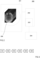
- FIG. 2 schematically illustrates an MRI system 200 according to the invention.
- said MRI system 200 comprises different coils 201 and respective coil controllers configured for generating magnetic fields and RF pulses in order to acquire an MRI signal from a biological object 206.
- Said MRI signal is transmitted by a receiver coil controller to a processing unit 202 comprising typically a memory 203 and connected to a display 204 for displaying images reconstructed from the received MRI signal.
- the MRI system 200 according to the invention is configured for carrying out the following method described in connection with Figures 3 to 5 .
- the MRI system 200 performs, at step 302, one or several T2-prepared inversion pulse series characterized each by an echo time, i.e. inter-pulse duration, TE p_ j, wherein said inter-pulse durations are different within a same scan and/or for each scan.
- An example of a T2-prepared inversion pulse sequence is provided by Fig. 4 showing one repetition time TR 414 of said sequence.
- the T2-prepared inversion module 41 (or pulse series) comprises notably a first pulse that is a tip-down RF pulse 411, e.g.
- a scan comprises multiple TR's to acquire an image.
- the present invention can be implemented as multiple scans each with a different echo time preparation TE p_ j or with one single scan that comprises different echo time preparations TE p_ j . In the preferred embodiment shown in Fig. 4-5 , the case of multiple scans is taken as illustration.
- the MRI system 200 launches, at step 303, an acquisition of an MRI recovery signal generated by at least a part of the biological object 206.
- each inversion time defines the time interval between the end of the T2-prepared inversion module 41 and the start of the corresponding readout RF excitation pulse sequence, i.e. readout block.
- the latter is for instance a segmented 3D MRI pulse sequence (e.g., FLASH [10]) employing an accelerated k-space sampling pattern [11].
- a center-out radial k-space ordering is used for encoding the prepared T2 contrast at the center of k-space.
- the slice-select gradient GSS, the in-plane phase-encoding gradient GPE and the readout (frequency-encoding) gradient GRO are controlled according to the specific type of readout block that is used, e.g. FLASH.
- Scan C_3 and C_4 uses longer echo times TE p , i.e. with TE p _2 ⁇ TE p _3 ⁇ TE p _4, shortest possible first inversion time, e.g.
- TI_2,3 and TI_2,4 are strictly greater than any of the inversion times TI_2,1 and TI_2,2, which are also strictly greater than any of the inversion times TI_1,1, TI_1,2, TI_1,3, and TI_1,4.
- the MRI system for instance its processing unit 202, is configured for reconstructing, from each received MRI signal S_i,j, an image I_i,j of the biological object part under investigation.
- each scan C_1,...,C_4 shown in Fig. 4 provides two 3D images, respectively one image at the first inversion time TI 1 and another image at the second inversion time TI 2 , resulting in overall eight images with different T 1 and T 2 weighting.
- Each image might be reconstructed using a compressed sensing algorithm [12].
- fast reconstruction methods or algorithm may also be suited for individual image reconstruction (e.g., parallel imaging, AI based, machine learning- or deep learning-based implementation, etc).
- an additional, fast B1+ map might be acquired by the MRI system according to the invention.
- the MRI system creates a voxel-wise signal from the intensity values that are provided by the different reconstructed images for a same voxel. Preferentially, said intensity values are concatenated to obtain said voxel-wise signal.
- the MRI system is configured for collecting, in each reconstructed image, the intensity value that is associated to the voxel that represents the same position within the imaged part of said biological object (i.e. for each voxel of a reconstructed image, the intensity value associated to the concerned voxel in said reconstructed image and the intensity value associated to the same voxel in all other reconstructed images are collected and associated to said voxel, i.e.
- a position within the imaged part This enables to construct or create, for each voxel, said voxel wise signal 51 as shown in Fig. 5 .
- the latter associates to each couple of time values (TE p _j,TI_i,j) 52, i.e. to each image, the intensity value 53 that has been obtained for the considered voxel in that image, i.e. for that couple of time values.
- the MRI system might automatically concatenate the intensity values 53 to obtain said voxel-wise signal 51.
- the MRI system preferentially its processing unit, or another processing unit not part of the MRI system, e.g. a stand-alone computer, is configured for fitting a physical model to the concatenated intensity values 53 to obtain at least one quantitative map.
- the MRI system might be configured for performing a numerical simulation of each scan C_j, more precisely, of each of the voxel-wise acquired signals. This might be performed before step 301, i.e. before starting the scanning process, or during the scanning process.
- Said numerical simulation is configured for generating, for each of said voxels, a set of simulated voxel-wise signals, associating, to each of said simulated voxel-wise signals, a value for one or several qMRI parameters, e.g. the corresponding value for T1, T2, B1+ for the considered voxel.
- Said set of simulated voxel-wise signals might populate a "dictionary" that can be used for imaging said biological part.
- different algorithms or physics-based models for estimating the qMRI parameters and simulating the acquired voxel-wise signals might be used, like EPG or conventional Bloch equations simulation.
- the MRI system preferentially its processing unit or said another processing unit, might be configured for performing a reconstruction, for at least one of said qMRI parameters, of a quantitative map representing said part of the biological object.
- the processing unit is configured for matching, for each voxel of the quantitative map, the created voxel-wise signal defined for that voxel and all simulated voxel-wise signals generated for that voxel, and assigning to the considered voxel in said quantitative map the value of said at least one qMRI parameter for which the best match has been obtained.
- the obtained quantitative MRI map might then be displayed on the display 204.
- said fast B1+ map might be used for selecting the simulated voxel-wise signals which are associated to B1+ values that match the acquired B1+ value for the considered voxel.
- "matching" means that the difference between the intensity values of the acquired voxel wise signal or acquired parameter (e.g. B1+) and the intensity values of the simulated voxel wise signal or simulated parameter (e.g. B1+) is smaller than a predefined value.
- different known techniques might be used for finding the best match between the simulated voxel-wise signals and the acquired one, for instance by using dot-product, RMSE, etc.
- the invention preferentially comprises at least 2, but up to N scans with different TE p and at least two but up to M_j readout blocks for each scan C_j, with different TIs, where M_j, N, TE p 's, and TIs are optimized to trade off accuracy of target T1 and T2 ranges with acquisition time.
- T1 and T2 maps might be simultaneously estimated/reconstructed from the voxel-wise "dictionary fitting" using the resulting magnitude images and optionally the B1+ map.
- a model-based approach which employs a physics model within the reconstruction, can be used to obtain quantitative maps directly from the acquired k-space.
- the present invention proposes a combination of a T2-prepared inversion module (or pulse sequence), notably the use of a tip-down/refocusing/tip-down pulse series, with a segmented readout sequence that includes multiple readout blocks following the magnetization preparation, i.e. said T2-prepared inversion pulse module.
- a T2-prepared inversion module or pulse sequence
- segmented readout sequence that includes multiple readout blocks following the magnetization preparation, i.e. said T2-prepared inversion pulse module.
- these images can be used as input to an algorithm that construct said voxel-wise signal for each voxel and compares the latter to simulated voxel-wise signals which are each associated to qMRI parameters like T1 or T2 in order to construct a quantitative map of said qMRI parameter(s) from the best matching. This enables notably to construct simultaneously a T1 and T2 quantitative map.
- the advantage of the present invention is that it makes possible to include both T1 and T2 relaxation parameters in the signal model, minimizing therefore measurement bias from relaxation mechanisms different than the one being probed.
- the advantage of the invention consists of using a simple signal model and a conventional acquisition technology (e.g., Cartesian k-space sampling, magnetization preparation, FLASH readout sequences) that is well supported by current scanner hardware, readily available for clinical use and, more specifically, well suited for high isotropic resolution imaging with large volumetric coverage.
- the proposed method further provides a lower sensitivity to B1+ inhomogeneity than the above-mentioned known in the art techniques, because of the low flip-angle readout out blocks, and a lower SAR compared to other T2 mapping methods like MESE based methods.
- different radio-frequency pulses for the T2-prepared inversion pulse sequence can be used, as long as said T2-prepared pulse sequence performs a T2-weighted inverted longitudinal magnetization before the readout blocks. Therefore, different adiabatic pulses like AFP, BIR4, etc., might be used for the tip-down or the refocusing in the T2-prepared inversion pulse sequence.
- T2-prepared inversion scans could also be combined with conventional T2-prepared scans that employ tip-down/refocusing/tip-up pulse series using short or long inter-pulse duration TE p .
- T2 different qMRI parameters, other than or in addition to T1, T2 can be probed by modifying the T2-prepared inversion pulse sequence and then subsequently estimated in the reconstruction, like relaxation times T1 ⁇ , T2p, magnetization transfer, diffusion, B1+, perfusion, fat and/or water fraction, etc.
- T2' relaxation time could be estimated with the proposed invention by using a modified T2-preparation where the timings of the refocusing pulses are changed and made asymmetrical with respect to the middle of the tip-down inter-pulse duration (i.e.
- the proposed method uses a variable-density Cartesian trajectory based on the spiral phyllotaxis pattern [13] and undersampled in phase- and slice-encoding dimensions.
- k-space sampling strategies like hybrid Cartesian-radial trajectories like stack-of-stars, "kooshball” 3D radial, 2D spiral, 3D variable density "cones” spirals, etc.
- different k-space ordering than the radial-like previously described can be used.
- the method according to the invention might use different acquisition strategies, like 2D, 3D slab-selective, 3D non-selective, and different sequence types for the readout blocks of the acquisition, like FLASH, bSSFP, etc.
- different metrics for dictionary fitting than a cross-product between absolute quantities can be used, like calculating a minimum root mean square error or an absolute difference.
- this invention proposes a qMRI method that simultaneously estimates multiple tissue MR parameters, including but not limited to T1 and T2 relaxation times, using at least two read-out blocks (e.g., FLASH or bSSFP type) after a T2-prepared inversion coupled with a physics-based numerical model/simulation for the reconstruction of quantitative maps.
- at least two read-out blocks e.g., FLASH or bSSFP type
Landscapes
- Physics & Mathematics (AREA)
- Health & Medical Sciences (AREA)
- High Energy & Nuclear Physics (AREA)
- Nuclear Medicine, Radiotherapy & Molecular Imaging (AREA)
- Condensed Matter Physics & Semiconductors (AREA)
- General Physics & Mathematics (AREA)
- Radiology & Medical Imaging (AREA)
- General Health & Medical Sciences (AREA)
- Engineering & Computer Science (AREA)
- Life Sciences & Earth Sciences (AREA)
- Signal Processing (AREA)
- Heart & Thoracic Surgery (AREA)
- Biophysics (AREA)
- Pathology (AREA)
- Biomedical Technology (AREA)
- Medical Informatics (AREA)
- Molecular Biology (AREA)
- Surgery (AREA)
- Animal Behavior & Ethology (AREA)
- Public Health (AREA)
- Veterinary Medicine (AREA)
- Neurology (AREA)
- Magnetic Resonance Imaging Apparatus (AREA)
Abstract
-performing (301), by the MRI system (200), N scans C_1,...,C_N, wherein each scan C_j, with j = 1, ...,N, comprises performing (302) one or several T2-prepared inversion pulse series, each followed by M_j readout blocks, wherein each magnetization preparation RF pulse series is a T2-prepared inversion pulse series (41) comprising multiple pulses (412) and characterized by an echo time, i.e. inter-pulse duration, TEp_j, configured for varying in order to obtain different T2 weightings, and an acquisition (303), by the MRI system (200) and during each readout block of an MRI recovery signal generated by at least a part of said biological object (206) , wherein for each readout block R_i,j, an MRI signal S_i,j is acquired by the MRI system at a different inversion time TI_i,j, with i=1,...,M_j, and M_j ≥ 2;
-reconstructing (304), for and from each MRI signal S_i,j, an image I_i,j of said part
-creating (305) a voxel-wise signal (51) by concatenating intensity values (53) obtained for a same voxel for the reconstructed images;
-fitting (306) a physical model to the concatenated intensity values (53) to obtain at least one qMRI map of one of said qMRI parameters.
Description
- The present invention falls within the field of magnetic resonance imaging (MRI) systems and methods. In particular, the present invention relates to a method and system for magnetic resonance imaging in which a simultaneous mapping of quantitative MRI parameters is carried out using a T2 prepared inversion magnetization preparation, and to a device for carrying out said method.
- Quantitative MRI (qMRI) plays an important role in the study of tissue- and organ-specific pathologies and has been widely adopted to support diagnosis, monitor therapy and interventions in many clinical applications. The main goal of qMRI techniques is to estimate tissue-specific parameters with minimal experimental bias. The estimation of an "absolute" MR tissue property has high interest because it may allow to detect pathological tissue as well as it could be used to follow-up pathological conditions for a single patient, compare patient groups, or compare single patient outcomes to normative values. Additionally, the measure of tissue properties is sought to be independent of the scanner hardware being used.
- Conventional qMRI methods use analytical solutions of spin evolutions to estimate tissue properties (e.g., T1 and T2 relaxation parameters in MRI). These techniques typically implement a series of inversion- or saturation-recovery measurements to estimate the longitudinal (spin-lattice) relaxation time, T1, and spin-echo measurements to estimate the transverse (spin-spin) relaxation time, T2. Although such measurements can provide excellent results and are often used as ground-truth, they require long acquisition times (TA) that are impractical for use in routine clinical examinations. Therefore, alternative methods have been introduced to determine T1 and T2 more rapidly. However, high isotropic spatial resolution and large volume coverage are still limited by long TA and/or signal-to-noise-ratio. Additionally, most of these methods are tailored to estimate a single MR parameter at a time and, in turn, their results are often biased by physical mechanisms that are not accounted for in the model.
- Over the last two decades, research has focused on qMRI techniques to simultaneously estimate T1 and T2 for increased accuracy and reduced experimental bias and acquisition time. In particular, a first method, DESPOT1/2 by Deoni et al. [1], uses variable flip angles to drive longitudinal and transversal magnetization to steady state with a spoiled gradient echo sequence to estimate T1 and subsequently with a steady-state free precession sequence for T2. While DESPOT1/2 is faster than conventional methods and offers high signal-to-noise ratio, its analytical solution may still suffer from experimental bias. A second method, called MR fingerprinting (MRF), had an important impact in the MRI community (
Ma et al. [2], US patent 8 723 518 B2 ). MRF introduced a paradigm shift from steady-state sequences to transient states achieved by continuously changing sequence parameters and, therefore, from analytical solutions to physics-based numerical models of those unique signal evolutions. By doing so, MRF deliberately entangles relaxation parameters evolution with unique experimental conditions and uses dictionary fitting to estimate tissue properties. The many degrees of freedom of MRF enable fast and simultaneous estimation of tissue properties. However, accuracy of such estimates may be limited by experimental factors mainly related to the nonconventional fast sequences used for the acquisition. - Another technique relevant for the present invention is the magnetization-prepared rapid gradient echo (MPRAGE) technique [3]. In this context, two methods for estimating T1 and T2 independently are of particular relevance:
- the first method is the "magnetization-prepared 2 rapid gradient echoes" (MP2RAGE) [4], which uses an inversion pulse to prepare the magnetization in each repetition time (TR), followed by the acquisition of two three-dimensional identical FLASH blocks at different inversion times (TI) (see
Figure 1A ). Two images can be reconstructed from one MP2RAGE scan: the short-TI (TI1) blocks result in a T1-weighted and the long-TI (TI2) blocks result in a proton-density-weighted image. A T1 map can be generated by using a combination of these two inversion images and a look-up table (pre-generated with Bloch equation simulations of the specific acquisition scheme) that assigns a T1 value to all possible intensities of the combined image. The MP2RAGE method is generally well suited for high, isotropic resolution T1 mapping of the entire brain as it uses non-selective excitation; - the second method is a T2-prepared rapid gradient echo sequence, called T2PRAGE hereafter. It uses a similar 3D segmented FLASH sequence but with a T2-preparation module [5] (see also
US20060253015A1 ) and only one FLASH readout block during the repetition time (instead of two blocks, seeFigure 1B ). T2 preparation (T2p) was first introduced by Brittain et al. [6] for imaging the coronary arteries and, generally, consists of a tip-down, refocusing, and tip-up pulses. First, the longitudinal magnetization is tipped on the transverse plane by a 90° pulse, then an echo time (TEp) follows, allowing transversal magnetization to relax (i.e., dephase). During this period, a series of 180° refocusing pulses is used to create a coherent transversal magnetization (echo) at the end of TEp, when the magnetization is tipped back up onto the longitudinal axis with a -90° pulse. Thus, T2 relaxation effects are imprinted into the longitudinal magnetization before imaging. In other words, after this procedure, the available longitudinal magnetization is scaled according to the T2 relaxation occurred during TEp. The FLASH readout block typically implements a center-out k-space trajectory ordering to encode the T2-prepared contrast in the first readouts close to the k-space center. The resulting image has a T2 weighting depending on TEp. A T2 map (i.e., a spatial representation of the T2 tissue property) can be obtained with this method by acquiring at least two images with different TEp and applying a voxel-wise fit of the mono-exponential signal equation:
- It is an objective of the present invention to find a system and method capable of simultaneously mapping MRI parameters such as T1, T2, and other tissue- or system-specific parameters like proton density or field inhomogeneity that overcome the above-mentioned disadvantages (i.e. notably limitations in accuracy, acquisition time, and experimental bias) and are suitable for clinical applications.
- Said objective is achieved according to the present invention by a system and method for simultaneous mapping of qMRI parameters using a T2 prepared inversion according to the object of the independent claims. Dependent claims present further advantages of the invention.
- The present invention proposes notably a qMRI method for mapping one or several qMRI parameters of a biological object with an MRI system, capable of simultaneously mapping several of said qMRI parameters, the method comprising the following steps:
- performing, by the MRI system, N scans C_1,...,C_N, with N ≥ 1, wherein each scan C_j, with j = 1,...,N, comprises:
- performing one or several magnetization preparation radio frequency (hereafter "RF") pulse series, each followed by M_j readout blocks (i.e. the scan C_j comprises, after each magnetization preparation RF pulse series, a number M_j of readout blocks, wherein said number M_j for scan C_j might be different from the number of readout blocks used for another of said scans. Optionally, for all scan, a same number of readout blocks follows each magnetization preparation RF pulse series), wherein two successive magnetization preparation RF pulse series are separated by a repetition time interval TR_j (i.e. two different scans might use each a different repetition time interval depending on the number of readout blocks after each magnetization preparation RF pulse series, all repetition time intervals between two successive magnetization preparation RF pulse series of a same scan being the same), wherein each magnetization preparation RF pulse series is a T2-prepared inversion pulse series comprising multiple pulses. Preferentially, it comprises the following series of successive RF pulses: a tip-down pulse, followed by, optionally, a pair of refocusing pulses, and ending with a tip-down pulse. Said series of successive pulses is notably configured for creating a T2 contrast on the transverse plane during the magnetization preparation and restoring longitudinal magnetization on the negative (ending tip-down) z-axis in order to generate T1 recovery entangled with T2 prepared contrast. Each magnetization preparation RF pulse series according to the invention is characterized by an echo time, TEp_j, i.e. first to last inter-pulse duration, wherein the MRI system is configured for varying said echo time TEp_j, i.e. the duration of the latter, notably within a same scan (i.e. the echo time TEp_j takes different values for each of the magnetization preparation RF pulse series of a same scan) and/or for each scan (i.e. the echo time TEp_j takes an identical value for all magnetization preparation RF pulse series of a same scan, but said identical value is different for each scan), for obtaining different T2 weightings. In other words, the MRI system is preferentially configured for varying said echo time TEp_j within said same scan, notably if N=1, so that each magnetization preparation RF pulse series of said same scan is characterized by a different echo time TEp_j and/or for varying said echo time TEp_j between different scans, so that the echo time TEp_j characterizing the magnetization preparation RF pulse series of a scan is different from the echo time TEp_j characterizing the magnetization preparation RF pulse series of the other scans, notably of all other scans. Preferentially, if N>1, each scan is characterized by a unique echo time TEp_j characterizing (i.e. being the same for) all magnetization preparation RF pulse series of the considered scan, that is at the same time different from the echo time TEp_j characterizing all other scans (i.e. the echo time TEp_j is unique within each scan, but is different for each scan). The notation "TEp_j" refers to an inter-pulse duration used for the scan C_j. As mentioned above, for a same scan, the magnetization preparation RF pulse series of said same scan might be characterized each by an echo time TEp_j whose value is different from the value of the echo time TEp_j of all other magnetization preparation RF pulse series of said same scan. The T2-prepared inversion pulse series is notably configured for inverting the longitudinal magnetization and for creating a T2-weighted recovery signal by generating translational relaxation before longitudinal inversion so that an acquired MRI recovery signal comprises both T1 and T2 weighting components. Preferentially, the T2-prepared inversion pulse series is an adiabatic T2-prepared inversion pulse series comprising two tip-down RF pulses temporally framing two refocusing RF pulses. In particular, the adiabatic T2-prepared inversion pulse series comprises the following series of temporally successive pulses: a first pulse that is a rectangular tip-down RF pulse, followed successively by a second pulse, a third pulse, and finally a fourth pulse, wherein the second and third pulses are both hyperbolic-secant-refocusing adiabatic RF pulses, and the fourth pulse is also a rectangular tip-down RF pulse. Preferentially, the first and fourth pulses are substantially identical, and the second and third pulses are also substantially identical. Of course, other adiabatic or non-adiabatic pulses can be used instead of said hyperbolic secant pulse previously mentioned as well as other adiabatic or non-adiabatic pulses may be used for tip-down instead of rectangular pulses. Preferentially, the inter-pulse duration TEp_j between the first pulse and the fourth pulse (i.e. the echo time of the T2-prepared inversion pulse series) is different for each scan C_j or even each repetition time interval TR_j in order to obtain different T2 weightings. Preferentially, the duration between the two refocusing pulses, e.g. between the second and third pulse, is equal to TEp/2. Preferentially, the duration between the first and second pulse is equal to TEp/4. The above-mentioned durations are notably measured from one pulse center (i.e. middle of pulse) to another pulse center (i.e. middle of pulse), wherein each pulse center is defined with respect to the width of the considered pulse;
- an acquisition, by the MRI system and during each readout block, of said MRI recovery signal generated by at least a part of said biological object, wherein for each readout block R_i,j, an MRI signal S_i,j is acquired by the MRI system at a different inversion time TI_i,j, with i=1,...,M_j, and M_j ≥ 2;
- reconstructing, for and from each MRI signal S_i,j, an image I_i,j of said part;
- creating a voxel-wise signal by concatenating intensity values of a same voxel of the reconstructed images. In other words, when considering the different reconstructed images I_i,j, a same voxel, representing thus a same position within the imaged biological part throughout the reconstructed images, will be associated to different intensity values in function of the different inversion times TI_i,j and inter-pulse durations TEp_j, one intensity value for each reconstructed images. The present invention proposes thus to collect, for the same voxel, the intensity value provided by each of the reconstructed images, the same voxel having thus different intensity values in function of the different parameter couples (TI_i,j;TEp_j). The voxel-wise signal can then be obtained by plotting for each voxel the intensity value of said voxel obtained in function of each couple (TI_i,j;TEp_j) with i=1,...,M_j and j=1,...,N, and ordering for instance said intensity values according to predefined criterion, e.g. from the first acquired intensity value to the last acquired intensity value. For instance, after completion of the N scans C_1,...,C_N, the voxel-wise signal is created by concatenating M_jxN intensity values of the same voxel of said reconstructed images of the N successive scans. Alternatively, a single scan (N=1) can be performed by the MRI system by interleaving a combination of L different inter-pulse durations TEp_j and M_j inversion times TI_i,1 resulting in multiple T1 and T2 sensitizations within said single scan, the latter producing therefore as many images as there are TI_i,1, i.e. M_j images associated with TEp_j, times the number of different TEp, i.e. L. In such a case, the voxel-wise signal is created by concatenating the M_jxL intensity values of the same voxel of the reconstructed images as explained before;
- fitting a physical model to the concatenated intensity values to obtain at least one qMRI map of one of said qMRI parameters. For instance, the system according to the invention can be configured for performing a numerical simulation of each scan C_j, wherein said numerical simulation is configured for generating, for each voxel, a set of simulated voxel-wise signals and, for providing, for each simulated voxel-wise signal, a value for one or several qMRI parameters, e.g. T1, T2, B1+, etc. Each simulated voxel-wise signal provides an intensity value for a concerned voxel in function of different values of (TI_i,j;TEp_j). Said set of simulated voxel-wise signals might be defined as a dictionary that will be used for quantitative map reconstruction using "dictionary fitting" as explained below, wherein for each simulated voxel-wise signal, a "look-up table" provides the corresponding values for said one or several qMRI parameters. Preferentially, a physics-based model is used for creating the simulated voxel-wise signal, wherein said physics-based model preferentially uses extended-phase-graph (EPG), or Bloch-Equations, or analytical solutions [9]. Then the system according to the invention can be configured for reconstructing, for at least one of said qMRI parameter, a quantitative map representing said imaged biological part by matching, for each voxel of said map, the created voxel-wise signal of the corresponding voxel in the reconstructed images and all simulated voxel-wise signals generated for said voxel, and assigning to the considered voxel in said quantitative map the value of said at least one qMRI parameter for which the best match has been obtained.
- In other words, the invention proposes thus a qMRI method using a novel magnetization prepared rapid gradient echo approach coupled preferentially with a dictionary matching method for quantitative parameter maps reconstruction. Contrary to the first method described above, i.e. said MP2RAGE sequence which uses a simple inversion for its magnetization preparation module, the present invention proposes to use a modified T2-prepared inversion module (T2pi) to invert the longitudinal magnetization while encoding T2 contrast in the subsequent T1 recovery. Contrary to said second method, i.e. said T2PRAGE sequence, the present invention proposes to use two or more readouts, and not only one.
- The present invention concerns also an MRI system or apparatus configured for simultaneous mapping of one or several qMRI parameters of a biological object by carrying out the steps of the previously described method.
- Said MRI system comprises for instance:
- an axial magnetic field coil and an axial magnetic field coil controller for controlling an axial magnetic field B0 generated by said axial magnetic field coil;
- a gradient coil and a gradient coil controller configured for controlling a magnetic field gradient G generated by said gradient coil;
- a RF coil and a RF coil controller configured for controlling a RF magnetic field B1 produced by the RF coil;
- a receiver coil, which can be the same as the RF coil, configured for detecting changes in a magnetization of a biological object to be imaged, and for communicating said changes to a receiver coil controller, which can be the same as the RF coil controller, the latter outputting an MRI signal to a processing unit comprising a processor, the processing unit being configured for processing the outputted MRI signal in order to reconstruct images of said biological object;
- a display for displaying the reconstructed images; characterized in that the processing unit is configured for automatically carrying out the previously described method.
- The foregoing has broadly outlined the features and technical advantages of the present disclosure so that those skilled in the art may better understand the detailed description that follows.
- Additional features and advantages of the disclosure will be described hereinafter that form the object of the claims. Those skilled in the art will appreciate that they may readily use the concept and the specific embodiment disclosed as a basis for modifying or designing other structures for carrying out the same purposes of the present disclosure.
- For a more complete understanding of the present disclosure, and the advantages thereof, reference is now made to the following descriptions taken in conjunction with the accompanying drawings, wherein like numbers designate like objects, and in which:
- Figure 1
- shows a schematic illustration of (A) an MP2RAGE pulse sequence and (B) a T2PRAGE pulse sequence according to prior art techniques;
- Figure 2
- is a schematic illustration of an MRI system according to the invention;
- Figure 3
- illustrates a flowchart of a method for qMRI mapping according to the invention;
- Figure 4
- schematically shows an adiabatic T2-prepared inversion pulse series according to the invention;
- Figure 5
- schematic illustration of a creation of a voxel-wise signal according to the invention;
-
Figure 1 schematically shows known in the art pulse sequences, which are an MP2RAGE pulse sequence (A) and a T2PRAGE pulse sequence (B) which have been described respectively with the so-called first method and second method. These pulse sequences are known in the art sequences and do not need further description here. -
Figure 2 schematically illustrates anMRI system 200 according to the invention. As known in the art, saidMRI system 200 comprisesdifferent coils 201 and respective coil controllers configured for generating magnetic fields and RF pulses in order to acquire an MRI signal from abiological object 206. Said MRI signal is transmitted by a receiver coil controller to aprocessing unit 202 comprising typically amemory 203 and connected to adisplay 204 for displaying images reconstructed from the received MRI signal. Contrary to prior art MRI systems, theMRI system 200 according to the invention is configured for carrying out the following method described in connection withFigures 3 to 5 . - At
step 301, theMRI system 200 performs one or several scans C_j, with j = 1, ...,N, of thebiological object 206. For each scan, theMRI system 200 performs, atstep 302, one or several T2-prepared inversion pulse series characterized each by an echo time, i.e. inter-pulse duration, TEp_j, wherein said inter-pulse durations are different within a same scan and/or for each scan. An example of a T2-prepared inversion pulse sequence is provided byFig. 4 showing onerepetition time TR 414 of said sequence. The T2-prepared inversion module 41 (or pulse series) comprises notably a first pulse that is a tip-downRF pulse 411, e.g. a rectangular tip-down RF pulse, followed by twosuccessive refocusing pulses 412, e.g. hyperbolic-secant adiabatic refocusing pulses, and ended with a fourth pulse that is also a tip-downRF pulse 413, preferentially a rectangular one. The inter-pulse duration TEp_j is measured from the middle of the first pulse width until the middle of the fourth pulse width. A scan comprises multiple TR's to acquire an image. As explained previously, the present invention can be implemented as multiple scans each with a different echo time preparation TEp_j or with one single scan that comprises different echo time preparations TEp_j . In the preferred embodiment shown inFig. 4-5 , the case of multiple scans is taken as illustration. - After performing said T2-
prepared inversion module 41, theMRI system 200 launches, atstep 303, an acquisition of an MRI recovery signal generated by at least a part of thebiological object 206. For this purpose, it is configured for generating, for said scan C_j and at different inversion times TI_i,j, with i=1,...,M_j with M_j ≥ 2, and before starting a next scan,M_j readout prepared inversion module 41 and the start of the corresponding readout RF excitation pulse sequence, i.e. readout block. The latter is for instance a segmented 3D MRI pulse sequence (e.g., FLASH [10]) employing an accelerated k-space sampling pattern [11]. A non-limiting illustration of an acquisition of said MRI recovery signal is shown inFig. 4 , wherein two readout blocks, i.e. M_j=2, are acquired in each repetition time interval TR at different inversion times TI_1,j and TI_2,j after the T2-preparedinversion pulse sequence 41. For each of said readout blocks, a center-out radial k-space ordering is used for encoding the prepared T2 contrast at the center of k-space. As known in the art, the slice-select gradient GSS, the in-plane phase-encoding gradient GPE and the readout (frequency-encoding) gradient GRO are controlled according to the specific type of readout block that is used, e.g. FLASH. -
Figure 5 illustrates a case where four scans C_j (i.e. N=4) were temporally successively performed, preferentially with the pulse sequence shown inFig. 4 , i.e. with M_j=M=2 readout blocks 421, 422 for j=1,...,N, i.e. according to a first inversion time TI1 and a second inversion time TI2. Each scan C_j, with j=1,...,4 combines thus different TEp's and TI's to probe a wide range of T2 and T1 contrasts. In particular, scan C_1 and C_2 use short echo times TEp, with TEp_1<TEp_2 with shortest possible inversion times TI_1,1 and TI_1,2 and medium long second inversion times TI_2,1 and TI_2,2, i.e. TI_2,1 > TI_1,1 and TI_2,2 > TI_1,2, with for instance TI_1,1 = TI_1,2 and TI_2,1 = TI_2,2. Scan C_3 and C_4 uses longer echo times TEp, i.e. with TEp_2 < TEp_3 < TEp_4, shortest possible first inversion time, e.g. TI_1,1 = TI_1,3 = TI_1,4 and a longer second inversion time, i.e. TI_2,3 > TI_2,2 and TI_2,4 > TI_2,2, or TI_2,3 > TI_2,1 and TI_2,4 > TI_2,1, with preferentially TI_2,3 = TI_2,4. In particular, TI_2,3 and TI_2,4 are strictly greater than any of the inversion times TI_2,1 and TI_2,2, which are also strictly greater than any of the inversion times TI_1,1, TI_1,2, TI_1,3, and TI_1,4. - At
step 304, the MRI system, for instance itsprocessing unit 202, is configured for reconstructing, from each received MRI signal S_i,j, an image I_i,j of the biological object part under investigation. For instance, each scan C_1,...,C_4 shown inFig. 4 provides two 3D images, respectively one image at the first inversion time TI1 and another image at the second inversion time TI2, resulting in overall eight images with different T1 and T2 weighting. Each image might be reconstructed using a compressed sensing algorithm [12]. Of course, other known in the art fast reconstruction methods or algorithm may also be suited for individual image reconstruction (e.g., parallel imaging, AI based, machine learning- or deep learning-based implementation, etc). - Preferentially, to account for biases due to B1 transmit field inhomogeneities, an additional, fast B1+ map might be acquired by the MRI system according to the invention.
- At
step 305, the MRI system creates a voxel-wise signal from the intensity values that are provided by the different reconstructed images for a same voxel. Preferentially, said intensity values are concatenated to obtain said voxel-wise signal. In other words, the MRI system is configured for collecting, in each reconstructed image, the intensity value that is associated to the voxel that represents the same position within the imaged part of said biological object (i.e. for each voxel of a reconstructed image, the intensity value associated to the concerned voxel in said reconstructed image and the intensity value associated to the same voxel in all other reconstructed images are collected and associated to said voxel, i.e. to a position within the imaged part). This enables to construct or create, for each voxel, said voxelwise signal 51 as shown inFig. 5 . The latter associates to each couple of time values (TEp_j,TI_i,j) 52, i.e. to each image, theintensity value 53 that has been obtained for the considered voxel in that image, i.e. for that couple of time values. Preferentially, the MRI system might automatically concatenate the intensity values 53 to obtain saidvoxel-wise signal 51. - At
step 306, the MRI system, preferentially its processing unit, or another processing unit not part of the MRI system, e.g. a stand-alone computer, is configured for fitting a physical model to the concatenated intensity values 53 to obtain at least one quantitative map. For instance, the MRI system might be configured for performing a numerical simulation of each scan C_j, more precisely, of each of the voxel-wise acquired signals. This might be performed beforestep 301, i.e. before starting the scanning process, or during the scanning process. Said numerical simulation is configured for generating, for each of said voxels, a set of simulated voxel-wise signals, associating, to each of said simulated voxel-wise signals, a value for one or several qMRI parameters, e.g. the corresponding value for T1, T2, B1+ for the considered voxel. Said set of simulated voxel-wise signals might populate a "dictionary" that can be used for imaging said biological part. In particular, different algorithms or physics-based models for estimating the qMRI parameters and simulating the acquired voxel-wise signals might be used, like EPG or conventional Bloch equations simulation. - Then, the MRI system, preferentially its processing unit or said another processing unit, might be configured for performing a reconstruction, for at least one of said qMRI parameters, of a quantitative map representing said part of the biological object. For generating said quantitative map, the processing unit is configured for matching, for each voxel of the quantitative map, the created voxel-wise signal defined for that voxel and all simulated voxel-wise signals generated for that voxel, and assigning to the considered voxel in said quantitative map the value of said at least one qMRI parameter for which the best match has been obtained. The obtained quantitative MRI map might then be displayed on the
display 204. - Preferentially, said fast B1+ map might be used for selecting the simulated voxel-wise signals which are associated to B1+ values that match the acquired B1+ value for the considered voxel. In particular, "matching" means that the difference between the intensity values of the acquired voxel wise signal or acquired parameter (e.g. B1+) and the intensity values of the simulated voxel wise signal or simulated parameter (e.g. B1+) is smaller than a predefined value. It has to be understood that different known techniques might be used for finding the best match between the simulated voxel-wise signals and the acquired one, for instance by using dot-product, RMSE, etc.
- In general, the invention preferentially comprises at least 2, but up to N scans with different TEp and at least two but up to M_j readout blocks for each scan C_j, with different TIs, where M_j, N, TEp's, and TIs are optimized to trade off accuracy of target T1 and T2 ranges with acquisition time. Thanks to the present invention, T1 and T2 maps might be simultaneously estimated/reconstructed from the voxel-wise "dictionary fitting" using the resulting magnitude images and optionally the B1+ map. In alternative to dictionary fitting, a model-based approach, which employs a physics model within the reconstruction, can be used to obtain quantitative maps directly from the acquired k-space.
- To summarize, the present invention proposes a combination of a T2-prepared inversion module (or pulse sequence), notably the use of a tip-down/refocusing/tip-down pulse series, with a segmented readout sequence that includes multiple readout blocks following the magnetization preparation, i.e. said T2-prepared inversion pulse module. Using arbitrary combinations of T2 preparation (TEp times) and inversion times result in images whose contrast depend on both T1 and T2. Finally, these images can be used as input to an algorithm that construct said voxel-wise signal for each voxel and compares the latter to simulated voxel-wise signals which are each associated to qMRI parameters like T1 or T2 in order to construct a quantitative map of said qMRI parameter(s) from the best matching. This enables notably to construct simultaneously a T1 and T2 quantitative map.
- Compared to T1 or T2 quantification techniques like MP2RAGE or T2-prepared rapid gradient echo sequences that estimate one relaxation parameter at the time, the advantage of the present invention is that it makes possible to include both T1 and T2 relaxation parameters in the signal model, minimizing therefore measurement bias from relaxation mechanisms different than the one being probed. Compared to other simultaneous T1/T2 quantification techniques like DESPOT1/2 or MRF, the advantage of the invention consists of using a simple signal model and a conventional acquisition technology (e.g., Cartesian k-space sampling, magnetization preparation, FLASH readout sequences) that is well supported by current scanner hardware, readily available for clinical use and, more specifically, well suited for high isotropic resolution imaging with large volumetric coverage.
- Advantageously, the proposed method further provides a lower sensitivity to B1+ inhomogeneity than the above-mentioned known in the art techniques, because of the low flip-angle readout out blocks, and a lower SAR compared to other T2 mapping methods like MESE based methods.
- Without departing from the general concept of the present invention, different radio-frequency pulses for the T2-prepared inversion pulse sequence can be used, as long as said T2-prepared pulse sequence performs a T2-weighted inverted longitudinal magnetization before the readout blocks. Therefore, different adiabatic pulses like AFP, BIR4, etc., might be used for the tip-down or the refocusing in the T2-prepared inversion pulse sequence. In general, T2-prepared inversion scans could also be combined with conventional T2-prepared scans that employ tip-down/refocusing/tip-up pulse series using short or long inter-pulse duration TEp.
- Also, different qMRI parameters, other than or in addition to T1, T2, can be probed by modifying the T2-prepared inversion pulse sequence and then subsequently estimated in the reconstruction, like relaxation times T1ρ, T2p, magnetization transfer, diffusion, B1+, perfusion, fat and/or water fraction, etc. In particular, T2' relaxation time could be estimated with the proposed invention by using a modified T2-preparation where the timings of the refocusing pulses are changed and made asymmetrical with respect to the middle of the tip-down inter-pulse duration (i.e. resulting in an uncomplete refocusing of the transverse magnetization), for instance for two refocusing pulses, by setting their timings at TEp/12 and TEp/4 (uncomplete refocusing) instead of TEp/4 and 3*TEp/4 (refocused)..
- Similarly, while the described method proposes to an additional B1+ map to mitigate bias from transmit field inhomogeneity, other maps might be used to take other effects into account if necessary, like B1-, B0 frequency offset, diffusion, etc.
- Preferentially, for the k-space sampling, the proposed method uses a variable-density Cartesian trajectory based on the spiral phyllotaxis pattern [13] and undersampled in phase- and slice-encoding dimensions. Of course, other k-space sampling strategies might be used, like hybrid Cartesian-radial trajectories like stack-of-stars, "kooshball" 3D radial, 2D spiral, 3D variable density "cones" spirals, etc. In particular, different k-space ordering than the radial-like previously described can be used.
- Advantageously, the method according to the invention might use different acquisition strategies, like 2D, 3D slab-selective, 3D non-selective, and different sequence types for the readout blocks of the acquisition, like FLASH, bSSFP, etc.
- Preferentially, different metrics for dictionary fitting than a cross-product between absolute quantities can be used, like calculating a minimum root mean square error or an absolute difference.
- Finally, while the method described a preferred embodiment based on a dictionary fitting procedure, other techniques for matching experimental data with simulated data, e.g. with a physics-based model, can be used to estimate the relaxation parameters (e.g., the physics-based model can be embedded in the reconstruction of the input images to output directly quantitative maps).
- To conclude, this invention proposes a qMRI method that simultaneously estimates multiple tissue MR parameters, including but not limited to T1 and T2 relaxation times, using at least two read-out blocks (e.g., FLASH or bSSFP type) after a T2-prepared inversion coupled with a physics-based numerical model/simulation for the reconstruction of quantitative maps.
-
- MRI
- magnetic resonance imaging
- MR
- magnetic resonance
- qMRI
- quantitative magnetic resonance imaging
- TA
- acquisition time
- MRF
- magnetic resonance fingerprinting
- TI
- inversion time
- TEp
- echo time
- RF
- radio frequency
- TR
- repetition time
-
- [1] Deoni SC, Rutt BK, Peters TM. Rapid combined T1 and T2 mapping using gradient recalled acquisition in the steady state. Magn Reson Med 2003;49(3):515-526.
- [2] Ma D, Gulani V, Seiberlich N, Liu K, Sunshine JL, Duerk JL, Griswold MA. Magnetic resonance fingerprinting. Nature 2013;495(7440):187-192.
- [3] Mugler JP, 3rd, Brookeman JR. Three-dimensional magnetization-prepared rapid gradient-echo imaging (3D MP RAGE). Magn Reson Med 1990;15(1):152-157
- [4] Marques JP, Kober T, Krueger G, van der Zwaag W, Van de Moortele PF, Gruetter R. MP2RAGE, a self bias-field corrected sequence for improved segmentation and T1-mapping at high field. Neuroimage 2010;49(2):1271-1281.
- [5] Nezafat R, Stuber M, Ouwerkerk R, Gharib AM, Desai M, Pettigrew RI. B1 insensitive T2 preparation for improved coronary magnetic resonance angiography at 3T. Magn Reson Med 2006;In Press.
- [6] Brittain JH, Hu BS, Wright GA, Meyer CH, Macovski A, Nishimura DG. Coronary angiography with magnetization-prepared T2 contrast. Magn Reson Med 1995;33(5):689-696.
- [7] Giri S, Chung YC, Merchant A, Mihai G, Rajagopalan S, Raman SV, Simonetti OP. T2 quantification for improved detection of myocardial edema. J Cardiovasc Magn Reson 2009;11:56.
- [8] van Heeswijk RB, Feliciano H, Bongard C, Bonanno G, Coppo S, Lauriers N, Locca D, Schwitter J, Stuber M. Free-breathing 3 T magnetic resonance T2-mapping of the heart. JACC Cardiovasc Imaging 2012;5(12):1231-1239.
- [9] Cloos MA, Knoll F, Zhao T, Block KT, Bruno M, Wiggins GC, Sodickson DK. Multiparametric imaging with heterogeneous radiofrequency fields. Nat Commun 2016;7:12445.
- [10] Frahm J, Haase A, Matthaei D. Rapid NMR imaging of dynamic processes using the FLASH technique. Magn Reson Med 1986;3(2):321-327.
- [11] Forman C, Piccini D, Grimm R, Hutter J, Hornegger J, Zenge MO. High-resolution 3D whole-heart coronary MRA: a study on the combination of data acquisition in multiple breath-holds and 1D residual respiratory motion compensation. MAGMA 2014.
- [12] Wetzl J, Forman C, Wintersperger BJ, D'Errico L, Schmidt M, Mailhe B, Maier A, Stalder AF. High-resolution dynamic CE-MRA of the thorax enabled by iterative TWIST reconstruction. Magn Reson Med 2017;77(2):833-840.
- [13] Forman C, Piccini D, Grimm R, Hutter J, Hornegger J, Zenge MO. High-resolution 3D whole-heart coronary MRA: a study on the combination of data acquisition in multiple breath-holds and 1D residual respiratory motion compensation. MAGMA 2014.
Claims (13)
- Quantitative Magnetic Resonance Imaging, hereafter qMRI, method for mapping one or several qMRI parameters of a biological object (206) with an MRI system (200), the method comprising the following steps:- performing (301), by the MRI system (200), N scans C_1,...,C_N, wherein each scan C_j, with j = 1,...,N, comprises:- performing (302) one or several magnetization preparation radio frequency (hereafter "RF") pulse series, each followed by M_j readout blocks, wherein two successive magnetization preparation RF pulse series are separated by a repetition time interval TR_j (414), wherein each magnetization preparation RF pulse series is a T2-prepared inversion pulse series (41) comprising multiple pulses (412) and characterized by an echo time, i.e. inter-pulse duration, TEp_j, wherein said inter-pulse duration is configured for varying in order to obtain different T2 weightings;- an acquisition (303), by the MRI system (200) and during each readout block, of an MRI recovery signal generated by at least a part of said biological object (206), wherein for each readout block R_i,j, an MRI signal S_i,j is acquired by the MRI system at a different inversion time TI_i,j, with i=1,...,M_j, and M_j ≥ 2;- reconstructing (304), for and from each MRI signal S_i,j, an image I_i,j of said part;- creating (305) a voxel-wise signal (51) by concatenating intensity values (53) obtained for a same voxel for the reconstructed images;- fitting (306) a physical model to the concatenated intensity values (53) to obtain at least one qMRI map of one of said qMRI parameters.
- The qMRI method according to claim 1, wherein the echo time TEp_j takes different values for each of the magnetization preparation RF pulse series of a same scan, or an identical value for all magnetization preparation RF pulse series of a same scan, said identical value being different for each scan.
- The qMRI method according to claim 1 or 2, wherein said fitting is a dictionary fitting that comprises:- performing a numerical simulation of each scan C_j, wherein said numerical simulation is configured for generating, for each voxel, a set of simulated voxel-wise signals and, for providing, for each simulated voxel-wise signal, a value for one or several qMRI parameters;- reconstructing, for at least one of said qMRI parameters, a quantitative map representing said imaged biological part by matching, for each voxel of said quantitative map, the created voxel-wise signal of the corresponding voxel in the reconstructed images and all simulated voxel-wise signals generated for said voxel, and assigning to the considered voxel in said quantitative map the value of said at least one qMRI parameter for which the best match has been obtained.
- The qMRI method according to claim 3, characterized in that said physics-based model is used for creating the simulated voxel-wise signal.
- The qMRI method according to claim 3 or 4, comprising acquiring an additional map for selecting the set of simulated voxel-wise signals to be matched with the acquired voxel-wise signal (51).
- The qMRI method according to claim 5, wherein said additional map is one of the following maps:- a B1+ map;- a B1- map;- a B0 frequency offset map;- a diffusion map.
- The qMRI method according to one of the claims 1 to 6, wherein the T2-prepared inversion pulse series (41) is adiabatic or non-adiabatic.
- The qMRI method according to claim 7, wherein the T2-prepared inversion pulse series (41) is an adiabatic T2-prepared inversion pulse sequence comprising two tip-down RF pulses (411, 413) temporally framing two refocusing adiabatic RF pulses (412), wherein the time interval between the middle of the first tip-down RF pulse and the middle of the last tip-down RF pulse is said inter-pulse duration TEp_j .
- The qMRI method according to claim 8, wherein the adiabatic T2-prepared inversion pulse series (41) comprises the following series of temporally successive pulses: a first pulse that is a rectangular tip-down RF pulse, followed successively by a second pulse, a third pulse, and finally a fourth pulse, wherein the second and third pulses are both hyperbolic-secant-refocusing adiabatic RF pulses, and the fourth pulse is a rectangular tip-down RF pulse.
- The qMRI method according to one of the claims 1 to 9, wherein the voxel-wise signal (51) is obtained by plotting for each voxel the intensity value of said voxel obtained in function of each couple (TI_i,j;TEp_j).
- The qMRI method according to one of the claims 1 to 10, wherein said qMRI parameters include:- T1 relaxation time; and/or- T2 relaxation time; and/or- T2* and/or T2' relaxation time; and/or- B1+ RF field; and/or- proton density; and/or- T1ρ and/or T2p relaxation time; and/or- a magnetization transfer parameter; and/or- a diffusion parameter; and/or- a perfusion parameter; and/or- a fat and/or water fraction parameter.
- The qMRI method according to one of the claims 1 to 11, wherein the physical model uses extended-phase-graph, or Bloch-Equations, or analytical solutions.
- MRI system (200) configured for carrying out the qMRI method according to one of the claims 1 to 12.
Priority Applications (3)
| Application Number | Priority Date | Filing Date | Title |
|---|---|---|---|
| EP22168303.0A EP4261558B1 (en) | 2022-04-14 | 2022-04-14 | A method and system for simultaneous mapping of quantitative mri parameters using a t2 prepared inversion |
| CN202310386627.4A CN116908759A (en) | 2022-04-14 | 2023-04-12 | Method and system for simultaneous calibration of quantitative MRI parameters using inversion of T2 preparation |
| US18/300,604 US12336802B2 (en) | 2022-04-14 | 2023-04-14 | Method and system for simultaneous mapping of quantitative MRI parameters using a T2 prepared inversion |
Applications Claiming Priority (1)
| Application Number | Priority Date | Filing Date | Title |
|---|---|---|---|
| EP22168303.0A EP4261558B1 (en) | 2022-04-14 | 2022-04-14 | A method and system for simultaneous mapping of quantitative mri parameters using a t2 prepared inversion |
Publications (3)
| Publication Number | Publication Date |
|---|---|
| EP4261558A1 true EP4261558A1 (en) | 2023-10-18 |
| EP4261558B1 EP4261558B1 (en) | 2024-10-30 |
| EP4261558C0 EP4261558C0 (en) | 2024-10-30 |
Family
ID=81328362
Family Applications (1)
| Application Number | Title | Priority Date | Filing Date |
|---|---|---|---|
| EP22168303.0A Active EP4261558B1 (en) | 2022-04-14 | 2022-04-14 | A method and system for simultaneous mapping of quantitative mri parameters using a t2 prepared inversion |
Country Status (3)
| Country | Link |
|---|---|
| US (1) | US12336802B2 (en) |
| EP (1) | EP4261558B1 (en) |
| CN (1) | CN116908759A (en) |
Families Citing this family (3)
| Publication number | Priority date | Publication date | Assignee | Title |
|---|---|---|---|---|
| US12578407B2 (en) | 2021-04-15 | 2026-03-17 | The Regents Of The University Of California | Ultra-fast arterial spin labeling with narrow-band velocity-selective (NB-VS) labeling |
| US12607694B2 (en) * | 2023-08-17 | 2026-04-21 | The Regents Of The University Of California | Suppression of background tissue signals in velocity selective arterial spin labeling (VSASL) |
| CN118135096B (en) * | 2024-01-23 | 2025-04-08 | 中国科学院精密测量科学与技术创新研究院 | Ultra-high field T based on magnetic resonance fingerprint1,T2And T1ρQuantitative measurement method |
Citations (3)
| Publication number | Priority date | Publication date | Assignee | Title |
|---|---|---|---|---|
| US20060253015A1 (en) | 2005-04-25 | 2006-11-09 | The Goverment of the United State of America as represented by the Secretary of the | Adiabatic T2 preparation sequence for magnetic resonance imaging with reduced B1 sensitivity |
| US8723518B2 (en) | 2011-03-18 | 2014-05-13 | Nicole SEIBERLICH | Nuclear magnetic resonance (NMR) fingerprinting |
| US10761171B2 (en) * | 2015-06-22 | 2020-09-01 | Case Western Reserve University | Systems and methods for free-breathing three-dimensional magnetic resonance fingerprinting |
Family Cites Families (1)
| Publication number | Priority date | Publication date | Assignee | Title |
|---|---|---|---|---|
| US12181554B2 (en) * | 2021-12-20 | 2024-12-31 | Beth Israel Deaconess Medical Center, Inc. | System and method for quantitative parameter mapping using magnetic resonance images |
-
2022
- 2022-04-14 EP EP22168303.0A patent/EP4261558B1/en active Active
-
2023
- 2023-04-12 CN CN202310386627.4A patent/CN116908759A/en active Pending
- 2023-04-14 US US18/300,604 patent/US12336802B2/en active Active
Patent Citations (3)
| Publication number | Priority date | Publication date | Assignee | Title |
|---|---|---|---|---|
| US20060253015A1 (en) | 2005-04-25 | 2006-11-09 | The Goverment of the United State of America as represented by the Secretary of the | Adiabatic T2 preparation sequence for magnetic resonance imaging with reduced B1 sensitivity |
| US8723518B2 (en) | 2011-03-18 | 2014-05-13 | Nicole SEIBERLICH | Nuclear magnetic resonance (NMR) fingerprinting |
| US10761171B2 (en) * | 2015-06-22 | 2020-09-01 | Case Western Reserve University | Systems and methods for free-breathing three-dimensional magnetic resonance fingerprinting |
Non-Patent Citations (15)
| Title |
|---|
| BRITTAIN JHHU BSWRIGHT GAMEYER CHMACOVSKI ANISHIMURA DG: "Coronary angiography with magnetization-prepared T2 contrast", MAGN RESON MED, vol. 33, no. 5, 1995, pages 689 - 696, XP000620372 |
| CAAN, M.W.A.: "MP2RAGEME: T1, T2* and QSM mapping in one sequence at 7 Tesla", PROCEEDINGS OF THE INTERNATIONAL SOCIETY FOR MAGNETIC RESONANCE IN MEDICINE, JOINT ANNUAL MEETING ISMRM-ESMRMB, no. 34, 1 June 2018 (2018-06-01), Paris, France, XP040699243 * |
| CLOOS MAKNOLL FZHAO TBLOCK KTBRUNO MWIGGINS GCSODICKSON DK: "Multiparametric imaging with heterogeneous radiofrequency fields", NAT COMMUN, vol. 7, 2016, pages 12445 |
| FORMAN CPICCINI DGRIMM RHUTTER JHORNEGGER JZENGE MO: "High-resolution 3D whole-heart coronary MRA: a study on the combination of data acquisition in multiple breath-holds and 1D residual respiratory motion compensation", MAGMA, 2014 |
| FRAHM JHAASE AMATTHAEI D: "Rapid NMR imaging of dynamic processes using the FLASH technique", MAGN RESON MED, vol. 3, no. 2, 1986, pages 321 - 327 |
| GABRIELE BONANNO ET AL: "High-resolution T2 maps of the whole brain at 7 Tesla: a proof of concept study using adiabatic T2-prepared FLASH and compressed sensing", PROCEEDINGS OF THE 2021 ISMRM & SMRT ANNUAL MEETING & EXHIBITION, 15-20 MAY 2021, ISMRM, 2030 ADDISON STREET, 7TH FLOOR, BERKELEY, CA 94704 USA, no. 3047, 30 April 2021 (2021-04-30), XP040725066 * |
| GIRI SCHUNG YCMERCHANT AMIHAI GRAJAGOPALAN SRAMAN SVSIMONETTI OP: "T2 quantification for improved detection of myocardial edema", J CARDIOVASC MAGN RESON, vol. 11, 2009, pages 56, XP021068359 |
| HEULE R.: "Simultaneous Mapping of Longitudinal and Transverse Relaxation Times", PROCEEDINGS OF THE INTERNATIONAL SOCIETY FOR MAGNETIC RESONANCE IN MEDICINE, no. E920, 24 July 2020 (2020-07-24), XP040718969 * |
| JI SOOYEON ET AL: "Quad-Contrast Imaging: Simultaneous Acquisition of Four Contrast-Weighted Images (PD-Weighted, T2-Weighted, PD-FLAIR and T2-FLAIR Images) With Synthetic T1-Weighted Image, T1- and T2-Maps", IEEE TRANSACTIONS ON MEDICAL IMAGING, IEEE, USA, vol. 40, no. 12, 30 June 2021 (2021-06-30), pages 3617 - 3626, XP011890417, ISSN: 0278-0062, [retrieved on 20211129], DOI: 10.1109/TMI.2021.3093617 * |
| MA DGULANI VSEIBERLICH NLIU KSUNSHINE JLDUERK JLGRISWOLD MA: "Magnetic resonance fingerprinting", NATURE, vol. 495, no. 7440, 2013, pages 187 - 192 |
| MARQUES JPKOBER TKRUEGER GVAN DER ZWAAG WVAN DE MOORTELE PFGRUETTER R: "MP2RAGE, a self bias-field corrected sequence for improved segmentation and Tl-mapping at high field", NEUROIMAGE, vol. 49, no. 2, 2010, pages 1271 - 1281, XP026796256 |
| MUGLER JPBROOKEMAN JR: "Three-dimensional magnetization-prepared rapid gradient-echo imaging (3D MP RAGE", MAGN RESON MED, vol. 15, no. 1, 1990, pages 152 - 157, XP000161116 |
| NEZAFAT RSTUBER MOUWERKERK RGHARIB AMDESAI MPETTIGREW RI: "Bl insensitive T2 preparation for improved coronary magnetic resonance angiography at 3T", MAGN RESON MED, 2006 |
| VAN HEESWIJK RBFELICIANO HBONGARD CBONANNO GCOPPO SLAURIERS NLOCCA DSCHWITTER JSTUBER M: "Free-breathing 3 T magnetic resonance T2-mapping of the heart", JACC CARDIOVASC IMAGING, vol. 5, no. 12, 2012, pages 1231 - 1239 |
| WETZL JFORMAN CWINTERSPERGER BJD'ERRICO LSCHMIDT MMAILHE BMAIER ASTALDER AF: "High-resolution dynamic CE-MRA of the thorax enabled by iterative TWIST reconstruction", MAGN RESON MED, vol. 77, no. 2, 2017, pages 833 - 840 |
Also Published As
| Publication number | Publication date |
|---|---|
| EP4261558B1 (en) | 2024-10-30 |
| US20230329576A1 (en) | 2023-10-19 |
| US12336802B2 (en) | 2025-06-24 |
| CN116908759A (en) | 2023-10-20 |
| EP4261558C0 (en) | 2024-10-30 |
Similar Documents
| Publication | Publication Date | Title |
|---|---|---|
| Buonincontri et al. | MR fingerprinting with simultaneous B1 estimation | |
| US12336802B2 (en) | Method and system for simultaneous mapping of quantitative MRI parameters using a T2 prepared inversion | |
| US9625547B2 (en) | Magnetic resonance imaging method for the quantification of the T1 and/or T2 relaxation times in a sample | |
| RU2605516C2 (en) | Magnetic resonance (mr) | |
| EP2699926B1 (en) | Spatially encoded phase-contrast mri | |
| EP2615470A1 (en) | MR imaging with B1 mapping | |
| Talagala et al. | Introduction to magnetic resonance imaging | |
| US10302729B2 (en) | Method and magnetic resonance apparatus for speed-compensated diffusion-based diffusion imaging | |
| US10247798B2 (en) | Simultaneous multi-slice MRI measurement | |
| Martinez | Introduction to MRI physics | |
| US20110025327A1 (en) | Method for radiofrequency mapping in magnetic resonance imaging | |
| JPWO2005000116A1 (en) | Magnetic resonance imaging system | |
| JP2796530B2 (en) | Magnetic resonance equipment | |
| Balaban et al. | Basic principles of cardiovascular magnetic resonance | |
| CN109983358A (en) | PROPELLER MR imaging | |
| EP2511696A1 (en) | MRI of chemical species having different resonance frequencies using an ultra-short echo time sequence | |
| JP2005537896A (en) | Spectroscopic imaging method, apparatus with means for performing the method, and use of the method in material property analysis | |
| EP4261556A1 (en) | A method and system for t1 mapping for tissue characterized by short-t2 relaxation in mri | |
| Börnert et al. | Single-shot-double-echo EPI | |
| Doran et al. | Rapid repetition of the “burst” sequence: the role of diffusion and consequences for imaging | |
| EP3385742A1 (en) | Method and apparatus for identifying at least one material comprised in a voxel | |
| US11333733B2 (en) | Method and apparatus for recording a magnetic resonance data record | |
| Hutter et al. | Pulse Sequences Combining Advanced Diffusion Encoding and Image Read-out | |
| US20250110195A1 (en) | Recording Diffusion-Weighted Measurement Data of an Examination Object Using a Magnetic Resonance System | |
| Althaus et al. | Fast 3D echo planar SSFP-based 1H spectroscopic imaging: demonstration on the rat brain in vivo |
Legal Events
| Date | Code | Title | Description |
|---|---|---|---|
| PUAI | Public reference made under article 153(3) epc to a published international application that has entered the european phase |
Free format text: ORIGINAL CODE: 0009012 |
|
| STAA | Information on the status of an ep patent application or granted ep patent |
Free format text: STATUS: THE APPLICATION HAS BEEN PUBLISHED |
|
| AK | Designated contracting states |
Kind code of ref document: A1 Designated state(s): AL AT BE BG CH CY CZ DE DK EE ES FI FR GB GR HR HU IE IS IT LI LT LU LV MC MK MT NL NO PL PT RO RS SE SI SK SM TR |
|
| RAP1 | Party data changed (applicant data changed or rights of an application transferred) |
Owner name: STICHTING RADBOUD UNIVERSITEIT Owner name: SIEMENS HEALTHINEERS AG |
|
| STAA | Information on the status of an ep patent application or granted ep patent |
Free format text: STATUS: REQUEST FOR EXAMINATION WAS MADE |
|
| 17P | Request for examination filed |
Effective date: 20240415 |
|
| RBV | Designated contracting states (corrected) |
Designated state(s): AL AT BE BG CH CY CZ DE DK EE ES FI FR GB GR HR HU IE IS IT LI LT LU LV MC MK MT NL NO PL PT RO RS SE SI SK SM TR |
|
| GRAP | Despatch of communication of intention to grant a patent |
Free format text: ORIGINAL CODE: EPIDOSNIGR1 |
|
| STAA | Information on the status of an ep patent application or granted ep patent |
Free format text: STATUS: GRANT OF PATENT IS INTENDED |
|
| RIC1 | Information provided on ipc code assigned before grant |
Ipc: G01R 33/563 20060101ALN20240621BHEP Ipc: G01R 33/561 20060101ALN20240621BHEP Ipc: G01R 33/48 20060101ALN20240621BHEP Ipc: G01R 33/28 20060101ALN20240621BHEP Ipc: G01R 33/24 20060101ALN20240621BHEP Ipc: G01R 33/56 20060101ALI20240621BHEP Ipc: G01R 33/50 20060101AFI20240621BHEP |
|
| INTG | Intention to grant announced |
Effective date: 20240719 |
|
| GRAS | Grant fee paid |
Free format text: ORIGINAL CODE: EPIDOSNIGR3 |
|
| GRAA | (expected) grant |
Free format text: ORIGINAL CODE: 0009210 |
|
| STAA | Information on the status of an ep patent application or granted ep patent |
Free format text: STATUS: THE PATENT HAS BEEN GRANTED |
|
| AK | Designated contracting states |
Kind code of ref document: B1 Designated state(s): AL AT BE BG CH CY CZ DE DK EE ES FI FR GB GR HR HU IE IS IT LI LT LU LV MC MK MT NL NO PL PT RO RS SE SI SK SM TR |
|
| REG | Reference to a national code |
Ref country code: GB Ref legal event code: FG4D |
|
| REG | Reference to a national code |
Ref country code: CH Ref legal event code: EP |
|
| REG | Reference to a national code |
Ref country code: DE Ref legal event code: R096 Ref document number: 602022007152 Country of ref document: DE |
|
| REG | Reference to a national code |
Ref country code: IE Ref legal event code: FG4D |
|
| U01 | Request for unitary effect filed |
Effective date: 20241030 |
|
| U07 | Unitary effect registered |
Designated state(s): AT BE BG DE DK EE FI FR IT LT LU LV MT NL PT RO SE SI Effective date: 20241106 |
|
| PG25 | Lapsed in a contracting state [announced via postgrant information from national office to epo] |
Ref country code: HR Free format text: LAPSE BECAUSE OF FAILURE TO SUBMIT A TRANSLATION OF THE DESCRIPTION OR TO PAY THE FEE WITHIN THE PRESCRIBED TIME-LIMIT Effective date: 20241030 Ref country code: IS Free format text: LAPSE BECAUSE OF FAILURE TO SUBMIT A TRANSLATION OF THE DESCRIPTION OR TO PAY THE FEE WITHIN THE PRESCRIBED TIME-LIMIT Effective date: 20250228 |
|
| PG25 | Lapsed in a contracting state [announced via postgrant information from national office to epo] |
Ref country code: ES Free format text: LAPSE BECAUSE OF FAILURE TO SUBMIT A TRANSLATION OF THE DESCRIPTION OR TO PAY THE FEE WITHIN THE PRESCRIBED TIME-LIMIT Effective date: 20241030 |
|
| PG25 | Lapsed in a contracting state [announced via postgrant information from national office to epo] |
Ref country code: NO Free format text: LAPSE BECAUSE OF FAILURE TO SUBMIT A TRANSLATION OF THE DESCRIPTION OR TO PAY THE FEE WITHIN THE PRESCRIBED TIME-LIMIT Effective date: 20250130 |
|
| PG25 | Lapsed in a contracting state [announced via postgrant information from national office to epo] |
Ref country code: GR Free format text: LAPSE BECAUSE OF FAILURE TO SUBMIT A TRANSLATION OF THE DESCRIPTION OR TO PAY THE FEE WITHIN THE PRESCRIBED TIME-LIMIT Effective date: 20250131 |
|
| PG25 | Lapsed in a contracting state [announced via postgrant information from national office to epo] |
Ref country code: PL Free format text: LAPSE BECAUSE OF FAILURE TO SUBMIT A TRANSLATION OF THE DESCRIPTION OR TO PAY THE FEE WITHIN THE PRESCRIBED TIME-LIMIT Effective date: 20241030 |
|
| PG25 | Lapsed in a contracting state [announced via postgrant information from national office to epo] |
Ref country code: RS Free format text: LAPSE BECAUSE OF FAILURE TO SUBMIT A TRANSLATION OF THE DESCRIPTION OR TO PAY THE FEE WITHIN THE PRESCRIBED TIME-LIMIT Effective date: 20250130 |
|
| U20 | Renewal fee for the european patent with unitary effect paid |
Year of fee payment: 4 Effective date: 20250417 |
|
| PG25 | Lapsed in a contracting state [announced via postgrant information from national office to epo] |
Ref country code: SM Free format text: LAPSE BECAUSE OF FAILURE TO SUBMIT A TRANSLATION OF THE DESCRIPTION OR TO PAY THE FEE WITHIN THE PRESCRIBED TIME-LIMIT Effective date: 20241030 |
|
| PG25 | Lapsed in a contracting state [announced via postgrant information from national office to epo] |
Ref country code: SK Free format text: LAPSE BECAUSE OF FAILURE TO SUBMIT A TRANSLATION OF THE DESCRIPTION OR TO PAY THE FEE WITHIN THE PRESCRIBED TIME-LIMIT Effective date: 20241030 |
|
| PG25 | Lapsed in a contracting state [announced via postgrant information from national office to epo] |
Ref country code: CZ Free format text: LAPSE BECAUSE OF FAILURE TO SUBMIT A TRANSLATION OF THE DESCRIPTION OR TO PAY THE FEE WITHIN THE PRESCRIBED TIME-LIMIT Effective date: 20241030 |
|
| PLBE | No opposition filed within time limit |
Free format text: ORIGINAL CODE: 0009261 |
|
| STAA | Information on the status of an ep patent application or granted ep patent |
Free format text: STATUS: NO OPPOSITION FILED WITHIN TIME LIMIT |
|
| 26N | No opposition filed |
Effective date: 20250731 |
|
| REG | Reference to a national code |
Ref country code: CH Ref legal event code: H13 Free format text: ST27 STATUS EVENT CODE: U-0-0-H10-H13 (AS PROVIDED BY THE NATIONAL OFFICE) Effective date: 20251125 |
|
| PG25 | Lapsed in a contracting state [announced via postgrant information from national office to epo] |
Ref country code: MC Free format text: LAPSE BECAUSE OF FAILURE TO SUBMIT A TRANSLATION OF THE DESCRIPTION OR TO PAY THE FEE WITHIN THE PRESCRIBED TIME-LIMIT Effective date: 20241030 |
|
| PG25 | Lapsed in a contracting state [announced via postgrant information from national office to epo] |
Ref country code: CH Free format text: LAPSE BECAUSE OF NON-PAYMENT OF DUE FEES Effective date: 20250430 |
|
| PG25 | Lapsed in a contracting state [announced via postgrant information from national office to epo] |
Ref country code: IE Free format text: LAPSE BECAUSE OF NON-PAYMENT OF DUE FEES Effective date: 20250414 |