EP4261449A1 - Multilayer hose - Google Patents
Multilayer hose Download PDFInfo
- Publication number
- EP4261449A1 EP4261449A1 EP21903010.3A EP21903010A EP4261449A1 EP 4261449 A1 EP4261449 A1 EP 4261449A1 EP 21903010 A EP21903010 A EP 21903010A EP 4261449 A1 EP4261449 A1 EP 4261449A1
- Authority
- EP
- European Patent Office
- Prior art keywords
- reinforcing
- hose
- reinforcing layer
- wire
- laminated
- Prior art date
- Legal status (The legal status is an assumption and is not a legal conclusion. Google has not performed a legal analysis and makes no representation as to the accuracy of the status listed.)
- Granted
Links
Images
Classifications
-
- F—MECHANICAL ENGINEERING; LIGHTING; HEATING; WEAPONS; BLASTING
- F16—ENGINEERING ELEMENTS AND UNITS; GENERAL MEASURES FOR PRODUCING AND MAINTAINING EFFECTIVE FUNCTIONING OF MACHINES OR INSTALLATIONS; THERMAL INSULATION IN GENERAL
- F16L—PIPES; JOINTS OR FITTINGS FOR PIPES; SUPPORTS FOR PIPES, CABLES OR PROTECTIVE TUBING; MEANS FOR THERMAL INSULATION IN GENERAL
- F16L11/00—Hoses, i.e. flexible pipes
- F16L11/04—Hoses, i.e. flexible pipes made of rubber or flexible plastics
- F16L11/08—Hoses, i.e. flexible pipes made of rubber or flexible plastics with reinforcements embedded in the wall
- F16L11/081—Hoses, i.e. flexible pipes made of rubber or flexible plastics with reinforcements embedded in the wall comprising one or more layers of a helically wound cord or wire
- F16L11/083—Hoses, i.e. flexible pipes made of rubber or flexible plastics with reinforcements embedded in the wall comprising one or more layers of a helically wound cord or wire three or more layers
-
- B—PERFORMING OPERATIONS; TRANSPORTING
- B32—LAYERED PRODUCTS
- B32B—LAYERED PRODUCTS, i.e. PRODUCTS BUILT-UP OF STRATA OF FLAT OR NON-FLAT, e.g. CELLULAR OR HONEYCOMB, FORM
- B32B1/00—Layered products having a non-planar shape
- B32B1/08—Tubular products
-
- B—PERFORMING OPERATIONS; TRANSPORTING
- B32—LAYERED PRODUCTS
- B32B—LAYERED PRODUCTS, i.e. PRODUCTS BUILT-UP OF STRATA OF FLAT OR NON-FLAT, e.g. CELLULAR OR HONEYCOMB, FORM
- B32B25/00—Layered products comprising a layer of natural or synthetic rubber
- B32B25/04—Layered products comprising a layer of natural or synthetic rubber comprising rubber as the main or only constituent of a layer, which is next to another layer of the same or of a different material
-
- B—PERFORMING OPERATIONS; TRANSPORTING
- B32—LAYERED PRODUCTS
- B32B—LAYERED PRODUCTS, i.e. PRODUCTS BUILT-UP OF STRATA OF FLAT OR NON-FLAT, e.g. CELLULAR OR HONEYCOMB, FORM
- B32B2260/00—Layered product comprising an impregnated, embedded, or bonded layer wherein the layer comprises an impregnation, embedding, or binder material
-
- B—PERFORMING OPERATIONS; TRANSPORTING
- B32—LAYERED PRODUCTS
- B32B—LAYERED PRODUCTS, i.e. PRODUCTS BUILT-UP OF STRATA OF FLAT OR NON-FLAT, e.g. CELLULAR OR HONEYCOMB, FORM
- B32B2597/00—Tubular articles, e.g. hoses, pipes
Definitions
- This disclosure relates to a laminated hose.
- a laminated hose includes, for example, a high-pressure hose with a reinforcing layer formed by spirally wound reinforcing wires (see, for example, PTL 1 and PTL 2).
- the high-pressure hose includes a plurality of reinforcing layers laminated on the inner tube rubber layer.
- Such high-pressure hose must be densely wound with the reinforcing wires in each of the reinforcing layers to ensure pressure-resistant performance and durability performance.
- the durability performance of the laminated hose includes what is called oscillating durability performance.
- the oscillating durability performance refers to the durability performance when internal pressure is applied to the laminated hose while repeatedly bending the hose.
- the oscillating durability performance may be rather reduced if the flexibility of the laminated hose is decreased by the increased density of the reinforcing wires.
- the purpose of this disclosure is to provide a laminated hose that can achieve both pressure-resistant performance and oscillating durability performance.
- the laminated hose according to this disclosure is a laminated hose comprising a hose body and a plurality of reinforcing layers laminated on the outer circumferential side of the hose body, and each of the plurality of reinforcing layers includes a reinforcing wire, wherein a wire density of the reinforcing layer in all of the plurality of reinforcing layers is 90% or more and less than 96%. According to the laminated hose of this disclosure, it is possible to achieve both pressure-resistant performance and oscillating durability performance.
- the laminated hose according to this disclosure is a laminated hose comprising a hose body and a plurality of reinforcing layers laminated on the outer circumferential side of the hose body, and each of the plurality of reinforcing layers includes a reinforcing wire, wherein a wire density of the reinforcing layer in all of the plurality of reinforcing layers is 90% or more and less than 95%. According to the laminated hose of this disclosure, it is possible to achieve both pressure-resistant performance and oscillating durability performance.
- the wire density of the reinforcing layer in each of the plurality of reinforcing layers decreases from the innermost reinforcing layer closest to the hose body to the outermost reinforcing layer farthest from the hose body. In this case, both pressure-resistant performance and oscillating durability performance can be effectively achieved.
- a winding angle of the reinforcing wire in each of the plurality of reinforcing layers is 40° or more and 70° or less. In this case, 50° or more and 60° or less is particularly preferrable.
- the wire density of the reinforcing layer in each of the plurality of reinforcing layers does not exceed 100 % when the laminated hose is bent at a bending radius determined by the specifications of the laminated hose. In this case, oscillating durability performance can be further improved.
- the laminated hose is a wire spiral hose including the reinforcing wire wound in a spiral shape.
- the laminated hose can be manufactured simply.
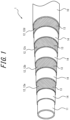
- Figure 1 is a partial perspective view schematically illustrating the internal structure of the laminated hose according to the first embodiment of the present disclosure.
- the laminated hose 1 comprises a hose body 11 and a plurality of reinforcing layers 12 laminated on the outer circumferential side of the hose body 11, and each of the plurality of reinforcing layers 12 includes a reinforcing wire 13.
- the laminated hose 1 consists of a plurality of cylindrical layers stacked concentrically.
- the laminated hose 1 functions as a flow path for distributing fluids and can also be used, for example, as a hydraulic hose.
- the laminated hose 1 is used as a high-pressure hose for distributing hydraulic oil from a pump in a device that is operated using hydraulic pressure.
- the sign 11 refers to the hose body, as described above.
- the hose body 11 is an inner layer arranged on the innermost side in the cylindrical layers that configure the laminated hose 1.
- the hose body 11 is an inner rubber layer containing rubber, i.e., a rubber member.
- the inside of the hose body 11 is filled with high-pressure hydraulic oil, i.e., liquid.
- the hydraulic fluid can, for example, transmit supply pressure from a hydraulic pump to a device, e.g., construction equipment, that operates using the pressure of the hydraulic fluid and operate the device.
- the sign 12 refers to the reinforcing layers 12.
- the reinforcing layers 12 are intermediate layers between the inner and outer layers of the laminated hose 1, among the cylindrical layers that configure the laminated hose 1.
- the reinforcing layers 12 include reinforcing wires 13.
- the reinforcing wires 13 consists of steel wire, i.e., wire rope, wound in a spiral /helical shape.
- the pressure-resistant performance of the laminated hose 1 is enhanced by the reinforcing layers 12.
- the laminated hose 1 is provided with a plurality of reinforcing layers 12 to further enhance its pressure-resistant performance. This allows the laminated hose 1 to handle high pressures, for example, of 80 MPa or higher.
- the laminated hose 1 comprises four reinforcing layers 12. As illustrated in Figure 1 , the winding direction of the reinforcing wire 13 in each of the four reinforcing layers 12 is opposite each other to the winding direction of the reinforcing wire 13 in the adjacent reinforcing layer 12 in the hose thickness direction, i.e., hose radial direction. This allows the laminated hose 1 to handle high pressures of, for example, 112 MPa to 168 MPa.
- the four reinforcing layers 12 are respectively a first reinforcing layer 12a, a second reinforcing layer 12b, a third reinforcing layer 12c, and a fourth reinforcing layer 12d.
- the first reinforcing layer 12a is the innermost reinforcing layer closest to the hose body 11.
- the second reinforcing layer 12b is an intermediate reinforcing layer farther from the hose body 11 than the first reinforcing layer 12a.
- the third reinforcing layer 12c is an intermediate reinforcing layer farther from the hose body 11 than the second reinforcing layer 12b.
- the fourth reinforcing layer 12d is the outermost reinforcing layer farther from the hose body 11 than the third reinforcing layer 12c.
- the fourth reinforcing layer 12d is the furthest reinforcing layer from the hose body 11.
- the sign 10 refers to the outer sheath layer.
- the outer sheath layer 10 is the outer layer arranged on the outermost side in the cylindrical layers that configure the laminated hose 1.
- the outer sheath layer 10 is a rubber layer containing rubber, i.e., rubber member.
- the outer sheath layer 10 is integrally formed with the hose body 11 via reinforcing layers 12 and intermediate rubber layers 13.
- the laminated hose 1 may also comprise six reinforcing layers 12.
- the laminated hose 1 can handle high pressures of, for example, 112 MPa to 168 MPa.
- those six reinforcing layers 12 are respectively a first reinforcing layer 12a, a second reinforcing layer 12b, a third reinforcing layer 12c, a fourth reinforcing layer 12d, a fifth reinforcing layer 12e omitted in the figures, and a sixth reinforcing layer 12f omitted in the figures.
- the first reinforcing layer 12a is the innermost reinforcing layer closest to the hose body 11.
- the second reinforcing layer 12b is an intermediate reinforcing layer farther from the hose body 11 than the first reinforcing layer 12a.
- the third reinforcing layer 12c is an intermediate reinforcing layer farther from the hose body 11 than the second reinforcing layer 12b.
- the fourth reinforcing layer 12d is an intermediate reinforcing layer farther from the hose body 11 than the third reinforcing layer 12c.
- the fifth reinforcing layer 12e is an intermediate reinforcing layer farther from the hose body 11 than the fourth reinforcing layer 12d.
- the sixth reinforcing layer 12f is the outermost reinforcing layer farther from the hose body 11 than the fifth reinforcing layer 12e. In this embodiment, the sixth reinforcing layer 12f is the furthest reinforcing layer from the hose body 11.
- the sign 14 refers to the intermediate rubber layers.
- the intermediate rubber layers 14, similarly to the reinforcing layers 12, are intermediate layers between the inner and outer layers of the laminated hose 1, among the cylindrical layers that configure the laminated hose 1.
- the intermediate rubber layers 14 are rubber member containing rubber.
- the intermediate rubber layers 14 include four intermediate rubber layers 14. The four intermediate rubber layers 14 are respectively disposed between the hose body 11 and the first reinforcing layer 12a, between the first reinforcing layer 12a and the second reinforcing layer 12b, between the second reinforcing layer 12b and the third reinforcing layer 12c, and between the third reinforcing layer 12c and the fourth reinforcing layer 12d.
- the laminated hose 1 provided with the plurality of reinforcing layers 12 which are stacked increasing the wire density ⁇ of the reinforcing layers 12 can ensure the pressure-resistant performance of the laminated hose 1, however may also reduce the oscillating durability performance thereof.
- the wire density ⁇ of each of the reinforcing layers 12 is increased to a certain density, which facilitates even alignment of the reinforcing wires 13 during manufacturing. Thereby, the quality of the laminated hose 1 becomes uniform.
- the wire density of the reinforcing layer in all of the plurality of reinforcing layers 12 in the laminated hose 1 is 90% or more and less than 95%, oscillating durability performance can be improved while maintaining the wire density ⁇ to ensure pressure-resistant performance. Therefore, according to the laminated hose 1, oscillating durability performance can be improved while ensuring pressure-resistant performance. This allows laminated hose 1 to achieve both pressure-resistant performance and oscillating durability performance. Further, the laminated hose 1 with the above wire density ⁇ also facilitates even alignment of the reinforcing wires 13 during manufacturing. Thereby, the quality of the laminated hose 1 becomes uniform.
- the wire density ⁇ of the reinforcing layer 12 is the ratio (%) of the area Sw of the reinforcing wires 13 per unit area S12 of the reinforcing layer 12.
- the unit area S12 of the reinforcing layer 12 can be expressed as any area of the reinforcing layer 12 when the laminated hose 1 is viewed in a plane. Alternatively, the unit area S12 of the reinforcing layer 12 can be expressed as any area of the reinforcing layer 12 when the reinforcing layer 12 is expanded.
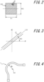
- Figure 2 schematically illustrates a part of the reinforcing layer 12 of the laminated hose 1.
- Figure 2 illustrates a plan view of the reinforcing layer 12, but a development view of the reinforcing layer 12 has a similar composition.
- the unit area S12 may be determined by the product (Ls * D12) of a certain length Ls along the extending direction d1 of the laminated hose 1 and the diameter D12 of the reinforcing layer 12 when the laminated hose 1 is extended in a straight line.
- the method for calculating the unit area S12 of the reinforcing layer 12 is not limited to this specific example.
- the wire density ⁇ of the reinforcing layer 12 may be calculated using four parameters: (1) the winding diameter Dw of the reinforcing wires 13, (2) the wire size (diameter) D13 of the reinforcing wire 13, (3) the number of reinforcing wires N13, and (4) the winding angle A13 of the reinforcing wires 13.
- ⁇ dK / ⁇ ⁇ WOD ⁇ d ⁇ cos ⁇ ⁇ 100 %
- p wire density
- d wire diameter (mm)
- K number of strikes (pcs)
- WOD braided outer diameter (mm)
- ⁇ braid angle
- the wire density 13 of the reinforcing layer 12 in each of the plurality of reinforcing layers 12 decreases from the innermost reinforcing layer 12a closest to the hose body 11 to the outermost reinforcing layer 12d farthest from the hose body 11.
- pressure-resistant performance can be effectively enhanced by increasing the wire density ⁇ inside the laminated hose 1, which is easily subjected to pressure.
- flexibility can be effectively enhanced. Therefore, according to the laminated hose 1, both pressure-resistant performance and oscillating durability performance can be effectively achieved.
- the wire density ⁇ of each of the four reinforcing layers 12 is set to decrease from the first reinforcing layer 12a to the fourth reinforcing layer 12d.
- the wire density ⁇ 1 of the first reinforcing layer 12a is the highest wire density, among the four reinforcing layers 12.
- the wire density ⁇ 2 of the second reinforcing layer 12b is lower than the wire density ⁇ 1 of the first reinforcing layer 12a.
- the wire density ⁇ 3 of the third reinforcing layer 12c is lower than the wire density ⁇ 2 of the second reinforcing layer 12b.
- the wire density ⁇ 4 of the fourth reinforcing layer 12d is lower than the wire density ⁇ 3 of the third reinforcing layer 12c. Therefore, in this embodiment, the wire density ⁇ 4 of the fourth reinforcing layer 12d is the lowest among the four reinforcing layers 12.
- the winding angle A of the reinforcing wires 13 in each of the plurality of reinforcing layer 12 is between 40° and 70°. In this case, between 50° and 60° is particularly suitable.
- Figure 3 schematically illustrates the wound state of the reinforcing wire 13 taking, as an example, a portion of the reinforcing wire 13 included in the reinforcing layer 12 in Figure 2 .
- the laminated hose 1 all of the reinforcing layers 12 from the first reinforcing layer 12a to the fourth reinforcing layer 12d are set so that the winding angle A13 of the reinforcing wires 13 is 50 degrees or more and 60 degrees or less.
- a specific example of the winding angle A13 of the reinforcing wire 13 is, as illustrated in Figure 3 , the acute side angle that the centerline L13 of the reinforcing wire 13 makes with respect to the extending direction d1 of the laminated hose 1.
- the winding angle A13 of the reinforcing wire 13 is not limited to this example.
- the winding angle A13 of the reinforcing wire 13 may be, for example, an obtuse side angle made with respect to the extending direction d1 of the laminated hose 1.
- the winding angle A13 of the reinforcing wire 13 may also be an obtuse or acute angle made with respect to the direction d2 (the radial direction of the laminated hose 1) that is perpendicular to the extending direction d1 of the laminated hose 1, in the plan view of the laminated hose 1.
- the wire density ⁇ of the reinforcing layer 12 in each of the plurality of reinforcing layers 12 does not exceed 100 % when the laminated hose 1 is bent at a bending radius determined by the specifications of the laminated hose 1.
- the reinforcing wires 13 in the reinforcing layer 12 are less likely to interfere with each other when the laminated hose 1 is bent. Therefore, according to the laminated hose 1, oscillating durability performance can be further improved.
- Figure 4 schematically illustrates the bending state of the laminated hose 1 when the laminated hose 1 is bent with a bending radius Rb.
- the wire bending density pb is the wire density ⁇ of the relevant reinforcing layer 12 when the laminated hose 1 is bent at the bending radius Rb determined by the specifications of the laminated hose 1.
- the wire density ⁇ of the reinforcing layer 12 is the wire density ⁇ of the reinforcing layer 12 when the laminated hose 1 is bent and viewed from the inner circumference in the radial direction of bending to the outer circumference.
- the bending radius Rb also called the allowable bending radius, is the limit of bending radius at which the hose can withstand the use as a laminated hose.
- the bending radius Rb is the radius of curvature generated at the innermost circumference in the bending radius direction of the laminated hose 1 when the laminated hose 1 is bent.
- the specifications of the laminated hose 1 include, for example, standards that are individually required each time the laminated hose is used, or standards that are predetermined by each hose manufacturer.
- the laminated hose 1 is set so that the wire bending density pb of the reinforcing layer 12 in each of the four reinforcing layers 12 does not exceed 100 % when the laminated hose 1 is bent at a bending radius Rb determined by the specifications of the laminated hose 1.
- each of the four reinforcing layers 12 is configured so that all of the wire bending densities pb of the four reinforcing layers 12 are substantially 100%.
- the error is "-0.3” against 100%, more suitably “-0.2” against 100%. That is, in the laminated hose 1, the wire bending density pb of all four reinforcing layers 12, when the laminated hose 1 is bent at a bending radius Rb, is between 99.5% and 100%, suitably between 99.7% and 100%, more suitably between 99.8% and 100%.
- the laminated hose 1 is a wire spiral hose with the reinforcing wires 13 wound in a spiral shape.
- the reinforcing wire 13 in the reinforcing layer 12 can be arranged by wrapping them in a spiral shape.
- the laminated hose 1 can be manufactured simply.
- the laminated hose 1 is a wire spiral hose.
- the reinforcing layer 12 is a spiral wire layer including at least one reinforcing wire 13 wound in a spiral shape.
- the winding direction of the reinforcing wires 13 in the reinforcing layers 12 is opposite each other to the winding direction of the reinforcing wires 13 in the adjacent reinforcing layers 12.
- Example 1 Comparative Example 1 Hose bore size [mm] 25 25 Wire density ⁇ 1 [%] 93.4 96.2 Wire density ⁇ 2 [%] 92.7 97.6 Wire density ⁇ 3 [%] 92.1 98.2 Wire density ⁇ 4 [%] 91.7 96.8 Wire bending density ⁇ b1 [%] 99.9 102.9 Wire bending density ⁇ b2 [%] 99.8 105.1 Wire bending density ⁇ b3 [%] 99.8 106.4 Wire bending density ⁇ b4 [%] 99.9 105.5 Calculated breakdown pressure [MPa] 159.0 169.0 Oscillating impulse counts [ten thousand times] 66.2 18.0
- Example 1 is a laminated hose with four reinforcing layers 12. Comparative Example 1 is a laminated hose with four reinforcing layers.
- the hose bore size is the inner diameter, i.e., diameter of inside, of the hose body 11.
- the unit is mm.
- the wire densities ⁇ 1 to ⁇ 4 are, respectively, the wire density ⁇ of the first reinforcing layer 12a, the wire density ⁇ of the second reinforcing layer 12b, the wire density ⁇ of the third reinforcing layer 12c, and the wire density ⁇ of the fourth reinforcing layer 12d.
- the wire bending densities ⁇ b1 to pb4 are, respectively, the wire bending density pb of the first reinforcing layer 12a, the wire bending density pb of the second reinforcing layer 12b, the wire bending density pb of the third reinforcing layer 12c, and the wire bending density pb of the fourth reinforcing layer 12d.
- the wire density ⁇ and the wire bending density pb are percentages (%).
- the calculated breakdown pressure is the limit pressure at which the laminated hose 1 will break down when a high-pressure liquid is pumped through it.
- the unit is MPa.
- the calculated breakdown pressure is an indicator for evaluating the pressure-resistant performance of the laminated hose 1. The higher the calculated breakdown pressure, the better the pressure-resistant performance.
- the calculated breakdown pressures in Example 1 are all 80 MPa or higher.
- the oscillating impulse counts is the number of times the laminated hose 1 is bent with a bending radius Rb.
- the unit is ten thousand times.
- the oscillating impulse counts is an indicator for evaluating the oscillating durability performance of the laminated hose 1. The higher the oscillating impulse counts, the better the oscillating durability performance.
- the bending radius Rb of Example 1 is 140 mm.
- the bending radius Rb of Comparative Example 1 is 620 mm.
- the oscillating impulse counts in Example 1 is 600,000 or more.
- Example 1 the wire density ⁇ of the reinforcing layer 12, in all four reinforcing layers 12, is 90% or more and less than 96%. Similarly, in Example 1, the wire density ⁇ of the reinforcing layer 12, in all four reinforcing layers 12, is 90% or more and less than 95%.
- Example 1 has improved oscillating durability performance while ensuring pressure-resistant performance. Therefore, it is clear from Table 1 that Example 1 is able to achieve both pressure-resistant performance and oscillating durability performance.
- the four reinforcement layers 12 are configured such that the wire density ⁇ of the reinforcement layers 12 decreases from the first reinforcement layer 12a to the fourth reinforcement layer 12d.
- the laminated hose 1 has each reinforcing layer 12 such that all of the wire bending density ⁇ b1 of the first reinforcing layer 12a to the wire bending density pb4 of the fourth reinforcing layer 12d are substantially 100%.
- the wire bending density ⁇ of the fourth reinforcement layer 12d is substantially 100%.
Landscapes
- Engineering & Computer Science (AREA)
- General Engineering & Computer Science (AREA)
- Mechanical Engineering (AREA)
- Rigid Pipes And Flexible Pipes (AREA)
Abstract
Description
- This disclosure relates to a laminated hose.
- A laminated hose includes, for example, a high-pressure hose with a reinforcing layer formed by spirally wound reinforcing wires (see, for example,
PTL 1 and PTL 2). The high-pressure hose includes a plurality of reinforcing layers laminated on the inner tube rubber layer. Such high-pressure hose must be densely wound with the reinforcing wires in each of the reinforcing layers to ensure pressure-resistant performance and durability performance. -
- PTL 1:
2013-151994A - PTL 2:
H9-26062A - However, increasing the density of the reinforcing wires will reduce the flexibility of the laminated hose. As a result, the durability performance of the laminated hose may be rather reduced due to the increased density of the reinforcing wires. For example, the durability performance of the laminated hose includes what is called oscillating durability performance. The oscillating durability performance refers to the durability performance when internal pressure is applied to the laminated hose while repeatedly bending the hose. The oscillating durability performance may be rather reduced if the flexibility of the laminated hose is decreased by the increased density of the reinforcing wires.
- Based on this, a lower density of reinforcing wires could be considered. However, a lower density of reinforcing wires may result in lower pressure-resistant performance. In addition, when the density of the reinforcing wires was reduced, it tended to be difficult for the reinforcing wires to line up evenly during manufacturing. Therefore, there is room for improvement in terms of achieving both pressure-resistant performance and oscillating durability performance in the conventional laminated hoses by improving oscillating durability performance while ensuring pressure-resistant performance.
- The purpose of this disclosure is to provide a laminated hose that can achieve both pressure-resistant performance and oscillating durability performance.
- The laminated hose according to this disclosure is a laminated hose comprising a hose body and a plurality of reinforcing layers laminated on the outer circumferential side of the hose body, and each of the plurality of reinforcing layers includes a reinforcing wire, wherein a wire density of the reinforcing layer in all of the plurality of reinforcing layers is 90% or more and less than 96%. According to the laminated hose of this disclosure, it is possible to achieve both pressure-resistant performance and oscillating durability performance.
- The laminated hose according to this disclosure is a laminated hose comprising a hose body and a plurality of reinforcing layers laminated on the outer circumferential side of the hose body, and each of the plurality of reinforcing layers includes a reinforcing wire, wherein a wire density of the reinforcing layer in all of the plurality of reinforcing layers is 90% or more and less than 95%. According to the laminated hose of this disclosure, it is possible to achieve both pressure-resistant performance and oscillating durability performance.
- In the laminated hose according to this disclosure, it is preferable that the wire density of the reinforcing layer in each of the plurality of reinforcing layers decreases from the innermost reinforcing layer closest to the hose body to the outermost reinforcing layer farthest from the hose body. In this case, both pressure-resistant performance and oscillating durability performance can be effectively achieved.
- In the laminated hose according to this disclosure, it is preferable that a winding angle of the reinforcing wire in each of the plurality of reinforcing layers is 40° or more and 70° or less. In this case, 50° or more and 60° or less is particularly preferrable.
- In the laminated hose according to this disclosure, it is preferable that the wire density of the reinforcing layer in each of the plurality of reinforcing layers does not exceed 100 % when the laminated hose is bent at a bending radius determined by the specifications of the laminated hose. In this case, oscillating durability performance can be further improved.
- In the laminated hose according to this disclosure, it is preferable that the laminated hose is a wire spiral hose including the reinforcing wire wound in a spiral shape. In this case, the laminated hose can be manufactured simply.
- According to this disclosure, it is possible to provide a laminated hose that can achieve both pressure-resistant performance and oscillating durability performance.
- In the accompanying drawings:
-
FIG. 1 is a partial perspective view schematically illustrating the internal structure of the laminated hose according to the first embodiment of the present disclosure; -
FIG. 2 schematically illustrates a part of the reinforcing layer of the laminated hose illustrated inFigure 1 ; -
FIG. 3 schematically illustrates the wound state of the reinforcing wire taking, as an example, a portion of the reinforcing wire included in the reinforcing layer inFigure 2 ; and -
FIG. 4 schematically illustrates the bending state of the laminated hose ofFig. 1 when the laminated hose is bent with a bending radius Rb. - The laminated hoses according to various embodiments of this disclosure are described below with reference to the drawings.
-
Figure 1 is a partial perspective view schematically illustrating the internal structure of the laminated hose according to the first embodiment of the present disclosure. As illustrated inFigure 1 , the laminatedhose 1 comprises ahose body 11 and a plurality of reinforcinglayers 12 laminated on the outer circumferential side of thehose body 11, and each of the plurality of reinforcinglayers 12 includes a reinforcingwire 13. - In this embodiment, the laminated
hose 1 consists of a plurality of cylindrical layers stacked concentrically. The laminatedhose 1 functions as a flow path for distributing fluids and can also be used, for example, as a hydraulic hose. Specifically, the laminatedhose 1 is used as a high-pressure hose for distributing hydraulic oil from a pump in a device that is operated using hydraulic pressure. - The following is a more specific description of the laminated
hose 1. - In
Figure 1 , thesign 11 refers to the hose body, as described above. Thehose body 11 is an inner layer arranged on the innermost side in the cylindrical layers that configure the laminatedhose 1. In this embodiment, thehose body 11 is an inner rubber layer containing rubber, i.e., a rubber member. In this embodiment, the inside of thehose body 11 is filled with high-pressure hydraulic oil, i.e., liquid. The hydraulic fluid can, for example, transmit supply pressure from a hydraulic pump to a device, e.g., construction equipment, that operates using the pressure of the hydraulic fluid and operate the device. - The
sign 12 refers to the reinforcinglayers 12. The reinforcinglayers 12 are intermediate layers between the inner and outer layers of the laminatedhose 1, among the cylindrical layers that configure the laminatedhose 1. The reinforcinglayers 12 include reinforcingwires 13. In this embodiment, the reinforcingwires 13 consists of steel wire, i.e., wire rope, wound in a spiral /helical shape. The pressure-resistant performance of the laminatedhose 1 is enhanced by the reinforcinglayers 12. - In this embodiment, the laminated
hose 1 is provided with a plurality of reinforcinglayers 12 to further enhance its pressure-resistant performance. This allows the laminatedhose 1 to handle high pressures, for example, of 80 MPa or higher. In this embodiment, the laminatedhose 1 comprises four reinforcinglayers 12. As illustrated inFigure 1 , the winding direction of the reinforcingwire 13 in each of the four reinforcinglayers 12 is opposite each other to the winding direction of the reinforcingwire 13 in the adjacent reinforcinglayer 12 in the hose thickness direction, i.e., hose radial direction. This allows the laminatedhose 1 to handle high pressures of, for example, 112 MPa to 168 MPa. - In this embodiment, the four reinforcing
layers 12 are respectively a first reinforcing layer 12a, a second reinforcing layer 12b, a third reinforcing layer 12c, and a fourth reinforcing layer 12d. The first reinforcing layer 12a is the innermost reinforcing layer closest to thehose body 11. The second reinforcing layer 12b is an intermediate reinforcing layer farther from thehose body 11 than the first reinforcing layer 12a. The third reinforcing layer 12c is an intermediate reinforcing layer farther from thehose body 11 than the second reinforcing layer 12b. The fourth reinforcing layer 12d is the outermost reinforcing layer farther from thehose body 11 than the third reinforcing layer 12c. In this embodiment, the fourth reinforcing layer 12d is the furthest reinforcing layer from thehose body 11. - The
sign 10 refers to the outer sheath layer. Theouter sheath layer 10 is the outer layer arranged on the outermost side in the cylindrical layers that configure thelaminated hose 1. In this embodiment, theouter sheath layer 10 is a rubber layer containing rubber, i.e., rubber member. Theouter sheath layer 10 is integrally formed with thehose body 11 via reinforcinglayers 12 and intermediate rubber layers 13. - The
laminated hose 1 may also comprise six reinforcinglayers 12. In this case, thelaminated hose 1 can handle high pressures of, for example, 112 MPa to 168 MPa. - When there are six reinforcing
layers 12, those six reinforcinglayers 12 are respectively a first reinforcing layer 12a, a second reinforcing layer 12b, a third reinforcing layer 12c, a fourth reinforcing layer 12d, a fifth reinforcing layer 12e omitted in the figures, and a sixth reinforcing layer 12f omitted in the figures. The first reinforcing layer 12a is the innermost reinforcing layer closest to thehose body 11. The second reinforcing layer 12b is an intermediate reinforcing layer farther from thehose body 11 than the first reinforcing layer 12a. The third reinforcing layer 12c is an intermediate reinforcing layer farther from thehose body 11 than the second reinforcing layer 12b. The fourth reinforcing layer 12d is an intermediate reinforcing layer farther from thehose body 11 than the third reinforcing layer 12c. The fifth reinforcing layer 12e is an intermediate reinforcing layer farther from thehose body 11 than the fourth reinforcing layer 12d. The sixth reinforcing layer 12f is the outermost reinforcing layer farther from thehose body 11 than the fifth reinforcing layer 12e. In this embodiment, the sixth reinforcing layer 12f is the furthest reinforcing layer from thehose body 11. - The
sign 14 refers to the intermediate rubber layers. The intermediate rubber layers 14, similarly to the reinforcinglayers 12, are intermediate layers between the inner and outer layers of thelaminated hose 1, among the cylindrical layers that configure thelaminated hose 1. In this embodiment, the intermediate rubber layers 14 are rubber member containing rubber. In this embodiment, the intermediate rubber layers 14 include four intermediate rubber layers 14. The four intermediate rubber layers 14 are respectively disposed between thehose body 11 and the first reinforcing layer 12a, between the first reinforcing layer 12a and the second reinforcing layer 12b, between the second reinforcing layer 12b and the third reinforcing layer 12c, and between the third reinforcing layer 12c and the fourth reinforcing layer 12d. - In the
laminated hose 1 provided with the plurality of reinforcinglayers 12 which are stacked, increasing the wire density ρ of the reinforcinglayers 12 can ensure the pressure-resistant performance of thelaminated hose 1, however may also reduce the oscillating durability performance thereof. - Based on that, if the wire density of the reinforcing layer in all of the plurality of reinforcing
layers 12 in thelaminated hose 1 is 90% or more and less than 96%, oscillating durability performance can be improved while maintaining the wire density ρ to ensure pressure-resistant performance. Therefore, according to thelaminated hose 1, oscillating durability performance can be improved while ensuring pressure-resistant performance. This allowslaminated hose 1 to achieve both pressure-resistant performance and oscillating durability performance. In addition, when the density ρ was reduced in the conventional configuration, it tended to be difficult for the reinforcing wires to line up evenly during manufacturing. In contrast, in thelaminated hose 1, the wire density ρ of each of the reinforcinglayers 12 is increased to a certain density, which facilitates even alignment of the reinforcingwires 13 during manufacturing. Thereby, the quality of thelaminated hose 1 becomes uniform. - In addition, if the wire density of the reinforcing layer in all of the plurality of reinforcing
layers 12 in thelaminated hose 1 is 90% or more and less than 95%, oscillating durability performance can be improved while maintaining the wire density ρ to ensure pressure-resistant performance. Therefore, according to thelaminated hose 1, oscillating durability performance can be improved while ensuring pressure-resistant performance. This allowslaminated hose 1 to achieve both pressure-resistant performance and oscillating durability performance. Further, thelaminated hose 1 with the above wire density ρ also facilitates even alignment of the reinforcingwires 13 during manufacturing. Thereby, the quality of thelaminated hose 1 becomes uniform. - The wire density ρ of the reinforcing
layer 12 is the ratio (%) of the area Sw of the reinforcingwires 13 per unit area S12 of the reinforcinglayer 12. The unit area S12 of the reinforcinglayer 12 can be expressed as any area of the reinforcinglayer 12 when thelaminated hose 1 is viewed in a plane. Alternatively, the unit area S12 of the reinforcinglayer 12 can be expressed as any area of the reinforcinglayer 12 when the reinforcinglayer 12 is expanded. -
Figure 2 schematically illustrates a part of the reinforcinglayer 12 of thelaminated hose 1.Figure 2 illustrates a plan view of the reinforcinglayer 12, but a development view of the reinforcinglayer 12 has a similar composition. As a specific example, the unit area S12 may be determined by the product (Ls * D12) of a certain length Ls along the extending direction d1 of thelaminated hose 1 and the diameter D12 of the reinforcinglayer 12 when thelaminated hose 1 is extended in a straight line. - However, the method for calculating the unit area S12 of the reinforcing
layer 12 is not limited to this specific example. For example, the wire density ρ of the reinforcinglayer 12 may be calculated using four parameters: (1) the winding diameter Dw of the reinforcingwires 13, (2) the wire size (diameter) D13 of the reinforcingwire 13, (3) the number of reinforcing wires N13, and (4) the winding angle A13 of the reinforcingwires 13. - An exemplary formula for calculating the wire density ρ of the reinforcing
layer 12 is as follows.
- In addition, in the
laminated hose 1, it is preferable that thewire density 13 of the reinforcinglayer 12 in each of the plurality of reinforcinglayers 12 decreases from the innermost reinforcing layer 12a closest to thehose body 11 to the outermost reinforcing layer 12d farthest from thehose body 11. In this case, pressure-resistant performance can be effectively enhanced by increasing the wire density ρ inside thelaminated hose 1, which is easily subjected to pressure. On the other hand, by suppressing the increase in the wire density ρ outside thelaminated hose 1, flexibility can be effectively enhanced. Therefore, according to thelaminated hose 1, both pressure-resistant performance and oscillating durability performance can be effectively achieved. - In the
laminated hose 1, the wire density ρ of each of the four reinforcinglayers 12 is set to decrease from the first reinforcing layer 12a to the fourth reinforcing layer 12d. In thelaminated hose 1, the wire density ρ1 of the first reinforcing layer 12a is the highest wire density, among the four reinforcinglayers 12. The wire density ρ2 of the second reinforcing layer 12b is lower than the wire density ρ1 of the first reinforcing layer 12a. The wire density ρ3 of the third reinforcing layer 12c is lower than the wire density ρ2 of the second reinforcing layer 12b. The wire density ρ4 of the fourth reinforcing layer 12d is lower than the wire density ρ3 of the third reinforcing layer 12c. Therefore, in this embodiment, the wire density ρ4 of the fourth reinforcing layer 12d is the lowest among the four reinforcinglayers 12. - Further, in the
laminated hose 1, it is preferable that the winding angle A of the reinforcingwires 13 in each of the plurality of reinforcinglayer 12 is between 40° and 70°. In this case, between 50° and 60° is particularly suitable. -
Figure 3 schematically illustrates the wound state of the reinforcingwire 13 taking, as an example, a portion of the reinforcingwire 13 included in the reinforcinglayer 12 inFigure 2 . In thelaminated hose 1, all of the reinforcinglayers 12 from the first reinforcing layer 12a to the fourth reinforcing layer 12d are set so that the winding angle A13 of the reinforcingwires 13 is 50 degrees or more and 60 degrees or less. A specific example of the winding angle A13 of the reinforcingwire 13 is, as illustrated inFigure 3 , the acute side angle that the centerline L13 of the reinforcingwire 13 makes with respect to the extending direction d1 of thelaminated hose 1. However, the winding angle A13 of the reinforcingwire 13 is not limited to this example. The winding angle A13 of the reinforcingwire 13 may be, for example, an obtuse side angle made with respect to the extending direction d1 of thelaminated hose 1. The winding angle A13 of the reinforcingwire 13 may also be an obtuse or acute angle made with respect to the direction d2 (the radial direction of the laminated hose 1) that is perpendicular to the extending direction d1 of thelaminated hose 1, in the plan view of thelaminated hose 1. - Further, in the
laminated hose 1, it is preferable that the wire density ρ of the reinforcinglayer 12 in each of the plurality of reinforcinglayers 12 does not exceed 100 % when thelaminated hose 1 is bent at a bending radius determined by the specifications of thelaminated hose 1. In this case, the reinforcingwires 13 in the reinforcinglayer 12 are less likely to interfere with each other when thelaminated hose 1 is bent. Therefore, according to thelaminated hose 1, oscillating durability performance can be further improved. -
Figure 4 schematically illustrates the bending state of thelaminated hose 1 when thelaminated hose 1 is bent with a bending radius Rb. The wire bending density pb is the wire density ρ of the relevant reinforcinglayer 12 when thelaminated hose 1 is bent at the bending radius Rb determined by the specifications of thelaminated hose 1. Specifically, the wire density ρ of the reinforcinglayer 12 is the wire density ρ of the reinforcinglayer 12 when thelaminated hose 1 is bent and viewed from the inner circumference in the radial direction of bending to the outer circumference. The bending radius Rb, also called the allowable bending radius, is the limit of bending radius at which the hose can withstand the use as a laminated hose. The bending radius Rb is the radius of curvature generated at the innermost circumference in the bending radius direction of thelaminated hose 1 when thelaminated hose 1 is bent. The specifications of thelaminated hose 1 include, for example, standards that are individually required each time the laminated hose is used, or standards that are predetermined by each hose manufacturer. - The
laminated hose 1 is set so that the wire bending density pb of the reinforcinglayer 12 in each of the four reinforcinglayers 12 does not exceed 100 % when thelaminated hose 1 is bent at a bending radius Rb determined by the specifications of thelaminated hose 1. In thelaminated hose 1, each of the four reinforcinglayers 12 is configured so that all of the wire bending densities pb of the four reinforcinglayers 12 are substantially 100%. - Here, "practically 100%" means including an error of "-0.5" against 100%. Suitably, the error is "-0.3" against 100%, more suitably "-0.2" against 100%. That is, in the
laminated hose 1, the wire bending density pb of all four reinforcinglayers 12, when thelaminated hose 1 is bent at a bending radius Rb, is between 99.5% and 100%, suitably between 99.7% and 100%, more suitably between 99.8% and 100%. - Further, in the
laminated hose 1, it is preferable that thelaminated hose 1 is a wire spiral hose with the reinforcingwires 13 wound in a spiral shape. In this case, the reinforcingwire 13 in the reinforcinglayer 12 can be arranged by wrapping them in a spiral shape. Thus, thelaminated hose 1 can be manufactured simply. - The
laminated hose 1 is a wire spiral hose. In thelaminated hose 1, the reinforcinglayer 12 is a spiral wire layer including at least one reinforcingwire 13 wound in a spiral shape. In this embodiment, the winding direction of the reinforcingwires 13 in the reinforcinglayers 12 is opposite each other to the winding direction of the reinforcingwires 13 in the adjacent reinforcing layers 12. - Table 1 below shows Example 1 and Comparative Example 1.
(Table 1) Example 1 Comparative Example 1 Hose bore size [mm] 25 25 Wire density ρ1 [%] 93.4 96.2 Wire density ρ2 [%] 92.7 97.6 Wire density ρ3 [%] 92.1 98.2 Wire density ρ4 [%] 91.7 96.8 Wire bending density ρb1 [%] 99.9 102.9 Wire bending density ρb2 [%] 99.8 105.1 Wire bending density ρb3 [%] 99.8 106.4 Wire bending density ρb4 [%] 99.9 105.5 Calculated breakdown pressure [MPa] 159.0 169.0 Oscillating impulse counts [ten thousand times] 66.2 18.0 - Example 1 is a laminated hose with four reinforcing
layers 12. Comparative Example 1 is a laminated hose with four reinforcing layers. - In Table 1, the hose bore size is the inner diameter, i.e., diameter of inside, of the
hose body 11. The unit is mm. - In Table 1, the wire densities ρ1 to ρ4 are, respectively, the wire density ρ of the first reinforcing layer 12a, the wire density ρ of the second reinforcing layer 12b, the wire density ρ of the third reinforcing layer 12c, and the wire density ρ of the fourth reinforcing layer 12d.
- The wire bending densities ρb1 to pb4 are, respectively, the wire bending density pb of the first reinforcing layer 12a, the wire bending density pb of the second reinforcing layer 12b, the wire bending density pb of the third reinforcing layer 12c, and the wire bending density pb of the fourth reinforcing layer 12d. The wire density ρ and the wire bending density pb are percentages (%).
- Furthermore, in Table 1, the calculated breakdown pressure is the limit pressure at which the
laminated hose 1 will break down when a high-pressure liquid is pumped through it. The unit is MPa. The calculated breakdown pressure is an indicator for evaluating the pressure-resistant performance of thelaminated hose 1. The higher the calculated breakdown pressure, the better the pressure-resistant performance. The calculated breakdown pressures in Example 1 are all 80 MPa or higher. - In addition, the oscillating impulse counts is the number of times the
laminated hose 1 is bent with a bending radius Rb. The unit is ten thousand times. The oscillating impulse counts is an indicator for evaluating the oscillating durability performance of thelaminated hose 1. The higher the oscillating impulse counts, the better the oscillating durability performance. The bending radius Rb of Example 1 is 140 mm. The bending radius Rb of Comparative Example 1 is 620 mm. The oscillating impulse counts in Example 1 is 600,000 or more. - In Example 1, the wire density ρ of the reinforcing
layer 12, in all four reinforcinglayers 12, is 90% or more and less than 96%. Similarly, in Example 1, the wire density ρ of the reinforcinglayer 12, in all four reinforcinglayers 12, is 90% or more and less than 95%. - Referring to Table 1, it can be evaluated that Example 1 has improved oscillating durability performance while ensuring pressure-resistant performance. Therefore, it is clear from Table 1 that Example 1 is able to achieve both pressure-resistant performance and oscillating durability performance.
- Referring to Example 1, the four
reinforcement layers 12 are configured such that the wire density ρ of the reinforcement layers 12 decreases from the first reinforcement layer 12a to the fourth reinforcement layer 12d. - Referring to Example 1, the
laminated hose 1 has each reinforcinglayer 12 such that all of the wire bending density ρb1 of the first reinforcing layer 12a to the wire bending density pb4 of the fourth reinforcing layer 12d are substantially 100%. - Referring to table 1, in the Example 1, the wire bending density ρ of the fourth reinforcement layer 12d is substantially 100%.
- The above describes an exemplary embodiment of this disclosure, and various changes can be made without departing from the scope of the claims. The various configurations employed in each of the above-mentioned embodiments can be replaced with each other as appropriate.
-
- 1
- Laminated hose
- 10
- Outer layer
- 11
- Hose body
- 12
- Reinforcing layer
- 12a
- First reinforcing layer (innermost reinforcing layer)
- 12b
- Second reinforcing layer
- 12c
- Third reinforcing layer
- 12d
- Fourth reinforcing layer (outermost reinforcing layer)
- 12e
- Fifth reinforcing layer
- 12f
- Sixth reinforcing layer (outermost reinforcing layer)
- S12
- Unit area of the reinforcing
layer 12 - 13
- Reinforcing wire
- A13
- Winding angle of the reinforcing wires
- 14
- Intermediate rubber layers
- Rb
- Bending radius
- ρ
- Wire density
- pb
- Wire bending density
Claims (6)
- A laminated hose comprising a hose body and a plurality of reinforcing layers laminated on the outer circumferential side of the hose body, and each of the plurality of reinforcing layers includes a reinforcing wire, wherein
a wire density of the reinforcing layer in all of the plurality of reinforcing layers is 90% or more and less than 96%. - A laminated hose comprising a hose body and a plurality of reinforcing layers laminated on the outer circumferential side of the hose body, and each of the plurality of reinforcing layers includes a reinforcing wire, wherein
a wire density of the reinforcing layer in all of the plurality of reinforcing layers is 90% or more and less than 95%. - The laminated hose according to claim 1 or 2, wherein the wire density of the reinforcing layer in each of the plurality of reinforcing layers decreases from the innermost reinforcing layer closest to the hose body to the outermost reinforcing layer farthest from the hose body.
- The laminated hose according to any one of claims 1 to 3, wherein a winding angle of the reinforcing wire in each of the plurality of reinforcing layers is 40° or more and 70° or less.
- The laminated hose according to any one of claims 1 to 4, wherein the wire density of the reinforcing layer in each of the plurality of reinforcing layers does not exceed 100 % when the laminated hose is bent at a bending radius determined by the specifications of the laminated hose.
- The laminated hose according to any one of claims 1 to 5, wherein the laminated hose is a wire spiral hose including the reinforcing wire wound in a spiral shape.
Applications Claiming Priority (2)
| Application Number | Priority Date | Filing Date | Title |
|---|---|---|---|
| JP2020206341A JP7588504B2 (en) | 2020-12-11 | 2020-12-11 | Multilayer Hose |
| PCT/JP2021/038142 WO2022123906A1 (en) | 2020-12-11 | 2021-10-14 | Multilayer hose |
Publications (3)
| Publication Number | Publication Date |
|---|---|
| EP4261449A1 true EP4261449A1 (en) | 2023-10-18 |
| EP4261449A4 EP4261449A4 (en) | 2024-05-29 |
| EP4261449B1 EP4261449B1 (en) | 2025-12-10 |
Family
ID=81973526
Family Applications (1)
| Application Number | Title | Priority Date | Filing Date |
|---|---|---|---|
| EP21903010.3A Active EP4261449B1 (en) | 2020-12-11 | 2021-10-14 | Multilayer hose |
Country Status (5)
| Country | Link |
|---|---|
| US (1) | US12680631B2 (en) |
| EP (1) | EP4261449B1 (en) |
| JP (1) | JP7588504B2 (en) |
| CN (1) | CN116568954B (en) |
| WO (1) | WO2022123906A1 (en) |
Family Cites Families (18)
| Publication number | Priority date | Publication date | Assignee | Title |
|---|---|---|---|---|
| US301417A (en) * | 1884-07-01 | Alexandeb wilkinson | ||
| US1984475A (en) * | 1930-02-14 | 1934-12-18 | Howard W Goodall | Hose |
| US1973756A (en) * | 1933-12-27 | 1934-09-18 | Daniel B Gish | Hose |
| US3948293A (en) * | 1972-07-13 | 1976-04-06 | Goodall Rubber Company | Hose construction and utilization |
| JPS5817283A (en) * | 1981-07-24 | 1983-02-01 | 横浜ゴム株式会社 | Flexible hose reinforced by metallic wire |
| US4384595A (en) * | 1981-09-14 | 1983-05-24 | Parker-Hannifin Corporation | Hose construction |
| JPS61192988A (en) * | 1985-02-20 | 1986-08-27 | 東海ゴム工業株式会社 | High-pressure hose |
| JPH0822447B2 (en) | 1991-03-18 | 1996-03-06 | 横浜ゴム株式会社 | High pressure hose reinforcement metal wire manufacturing method and high pressure hose |
| JPH0926062A (en) * | 1995-07-12 | 1997-01-28 | Yokohama Rubber Co Ltd:The | High pressure hose |
| JPH10185018A (en) * | 1996-12-27 | 1998-07-14 | Yokohama Rubber Co Ltd:The | High pressure hose |
| JPH11141751A (en) | 1997-09-05 | 1999-05-28 | Yokohama Rubber Co Ltd:The | High pressure rubber hose |
| EP1677040B1 (en) * | 2000-06-12 | 2010-08-11 | BHP Billiton Petroleum Pty Ltd | Hose connector |
| US7748412B2 (en) * | 2008-08-05 | 2010-07-06 | Veyance Technologies Inc. | Hose having a single reinforcing layer |
| JP6049264B2 (en) | 2012-01-25 | 2016-12-21 | 株式会社ブリヂストン | High pressure hose |
| WO2015050853A1 (en) * | 2013-10-02 | 2015-04-09 | E. I. Du Pont De Nemours And Company | Multilayer reinforced hose |
| CN103697251A (en) * | 2013-12-24 | 2014-04-02 | 苏州华东橡胶工业有限公司 | Heavy hydraulic hose with four layers of steel wires |
| JP6926413B2 (en) | 2016-08-10 | 2021-08-25 | 横浜ゴム株式会社 | hose |
| JP6988159B2 (en) | 2017-05-16 | 2022-01-05 | 横浜ゴム株式会社 | High pressure hose |
-
2020
- 2020-12-11 JP JP2020206341A patent/JP7588504B2/en active Active
-
2021
- 2021-10-14 WO PCT/JP2021/038142 patent/WO2022123906A1/en not_active Ceased
- 2021-10-14 CN CN202180083081.4A patent/CN116568954B/en active Active
- 2021-10-14 US US18/255,174 patent/US12680631B2/en active Active
- 2021-10-14 EP EP21903010.3A patent/EP4261449B1/en active Active
Also Published As
| Publication number | Publication date |
|---|---|
| CN116568954A (en) | 2023-08-08 |
| JP7588504B2 (en) | 2024-11-22 |
| JP2022093185A (en) | 2022-06-23 |
| EP4261449B1 (en) | 2025-12-10 |
| WO2022123906A1 (en) | 2022-06-16 |
| US12680631B2 (en) | 2026-07-14 |
| CN116568954B (en) | 2025-09-23 |
| US20230407997A1 (en) | 2023-12-21 |
| EP4261449A4 (en) | 2024-05-29 |
Similar Documents
| Publication | Publication Date | Title |
|---|---|---|
| CN120969594A (en) | Flexible pipelines for transporting oil fluids, including diffusion barriers | |
| JPS5859832A (en) | High bursting strength flexible composite hose | |
| CN103388457A (en) | Flexible pipe body with buoyancy element and method of producing same | |
| EP4261449B1 (en) | Multilayer hose | |
| CN103930701B (en) | Stacked reinforced hose | |
| JP7542328B2 (en) | hose | |
| US20180299037A1 (en) | High-pressure hose | |
| EP3002490B1 (en) | Fluid permeable hose carcass | |
| JP7401741B2 (en) | How to set the minimum bending radius of hoses and hoses | |
| JP6720826B2 (en) | Hose for filling hydrogen | |
| WO2024234416A1 (en) | Steel cord for engineering tire | |
| US11649911B2 (en) | Spiral hose | |
| JP6623800B2 (en) | Marine hose | |
| CN100432513C (en) | Special multi-layered flexible tube and mfg. method thereof | |
| CN224033270U (en) | PVC hose with multilayer composite structure | |
| JP5107140B2 (en) | Fluid transfer hose | |
| EP4428421A1 (en) | Fluid-conveying hose | |
| JP2005299727A (en) | High pressure rubber hose | |
| JP5798805B2 (en) | High pressure hose | |
| CN117067702B (en) | High-pressure rubber hose | |
| US8910668B2 (en) | Hose for transporting fluids | |
| JPS61201982A (en) | Marine hose | |
| JP4882253B2 (en) | High pressure rubber hose | |
| JP5056609B2 (en) | Fluid transfer hose | |
| JP2014206260A (en) | High pressure hose |
Legal Events
| Date | Code | Title | Description |
|---|---|---|---|
| STAA | Information on the status of an ep patent application or granted ep patent |
Free format text: STATUS: THE INTERNATIONAL PUBLICATION HAS BEEN MADE |
|
| PUAI | Public reference made under article 153(3) epc to a published international application that has entered the european phase |
Free format text: ORIGINAL CODE: 0009012 |
|
| STAA | Information on the status of an ep patent application or granted ep patent |
Free format text: STATUS: REQUEST FOR EXAMINATION WAS MADE |
|
| 17P | Request for examination filed |
Effective date: 20230518 |
|
| AK | Designated contracting states |
Kind code of ref document: A1 Designated state(s): AL AT BE BG CH CY CZ DE DK EE ES FI FR GB GR HR HU IE IS IT LI LT LU LV MC MK MT NL NO PL PT RO RS SE SI SK SM TR |
|
| DAV | Request for validation of the european patent (deleted) | ||
| DAX | Request for extension of the european patent (deleted) | ||
| A4 | Supplementary search report drawn up and despatched |
Effective date: 20240429 |
|
| RIC1 | Information provided on ipc code assigned before grant |
Ipc: F16L 11/08 20060101AFI20240423BHEP |
|
| GRAP | Despatch of communication of intention to grant a patent |
Free format text: ORIGINAL CODE: EPIDOSNIGR1 |
|
| STAA | Information on the status of an ep patent application or granted ep patent |
Free format text: STATUS: GRANT OF PATENT IS INTENDED |
|
| INTG | Intention to grant announced |
Effective date: 20250715 |
|
| GRAS | Grant fee paid |
Free format text: ORIGINAL CODE: EPIDOSNIGR3 |
|
| GRAA | (expected) grant |
Free format text: ORIGINAL CODE: 0009210 |
|
| STAA | Information on the status of an ep patent application or granted ep patent |
Free format text: STATUS: THE PATENT HAS BEEN GRANTED |
|
| P01 | Opt-out of the competence of the unified patent court (upc) registered |
Free format text: CASE NUMBER: UPC_APP_9422_4261449/2025 Effective date: 20251009 |
|
| AK | Designated contracting states |
Kind code of ref document: B1 Designated state(s): AL AT BE BG CH CY CZ DE DK EE ES FI FR GB GR HR HU IE IS IT LI LT LU LV MC MK MT NL NO PL PT RO RS SE SI SK SM TR |
|
| REG | Reference to a national code |
Ref country code: CH Ref legal event code: F10 Free format text: ST27 STATUS EVENT CODE: U-0-0-F10-F00 (AS PROVIDED BY THE NATIONAL OFFICE) Effective date: 20251210 Ref country code: GB Ref legal event code: FG4D |
|
| REG | Reference to a national code |
Ref country code: DE Ref legal event code: R096 Ref document number: 602021044355 Country of ref document: DE |
|
| REG | Reference to a national code |
Ref country code: IE Ref legal event code: FG4D |
|
| PG25 | Lapsed in a contracting state [announced via postgrant information from national office to epo] |
Ref country code: ES Free format text: LAPSE BECAUSE OF FAILURE TO SUBMIT A TRANSLATION OF THE DESCRIPTION OR TO PAY THE FEE WITHIN THE PRESCRIBED TIME-LIMIT Effective date: 20251210 |
|
| REG | Reference to a national code |
Ref country code: LT Ref legal event code: MG9D |
|
| PG25 | Lapsed in a contracting state [announced via postgrant information from national office to epo] |
Ref country code: NO Free format text: LAPSE BECAUSE OF FAILURE TO SUBMIT A TRANSLATION OF THE DESCRIPTION OR TO PAY THE FEE WITHIN THE PRESCRIBED TIME-LIMIT Effective date: 20260310 |
|
| PG25 | Lapsed in a contracting state [announced via postgrant information from national office to epo] |
Ref country code: HR Free format text: LAPSE BECAUSE OF FAILURE TO SUBMIT A TRANSLATION OF THE DESCRIPTION OR TO PAY THE FEE WITHIN THE PRESCRIBED TIME-LIMIT Effective date: 20251210 Ref country code: FI Free format text: LAPSE BECAUSE OF FAILURE TO SUBMIT A TRANSLATION OF THE DESCRIPTION OR TO PAY THE FEE WITHIN THE PRESCRIBED TIME-LIMIT Effective date: 20251210 |
|
| REG | Reference to a national code |
Ref country code: NL Ref legal event code: MP Effective date: 20251210 |
|
| PG25 | Lapsed in a contracting state [announced via postgrant information from national office to epo] |
Ref country code: RS Free format text: LAPSE BECAUSE OF FAILURE TO SUBMIT A TRANSLATION OF THE DESCRIPTION OR TO PAY THE FEE WITHIN THE PRESCRIBED TIME-LIMIT Effective date: 20260310 |
|
| PG25 | Lapsed in a contracting state [announced via postgrant information from national office to epo] |
Ref country code: LV Free format text: LAPSE BECAUSE OF FAILURE TO SUBMIT A TRANSLATION OF THE DESCRIPTION OR TO PAY THE FEE WITHIN THE PRESCRIBED TIME-LIMIT Effective date: 20251210 |
|
| PG25 | Lapsed in a contracting state [announced via postgrant information from national office to epo] |
Ref country code: BG Free format text: LAPSE BECAUSE OF FAILURE TO SUBMIT A TRANSLATION OF THE DESCRIPTION OR TO PAY THE FEE WITHIN THE PRESCRIBED TIME-LIMIT Effective date: 20251210 |
|
| REG | Reference to a national code |
Ref country code: AT Ref legal event code: MK05 Ref document number: 1866446 Country of ref document: AT Kind code of ref document: T Effective date: 20251210 |
|
| PG25 | Lapsed in a contracting state [announced via postgrant information from national office to epo] |
Ref country code: NL Free format text: LAPSE BECAUSE OF FAILURE TO SUBMIT A TRANSLATION OF THE DESCRIPTION OR TO PAY THE FEE WITHIN THE PRESCRIBED TIME-LIMIT Effective date: 20251210 |
|
| PG25 | Lapsed in a contracting state [announced via postgrant information from national office to epo] |
Ref country code: LT Free format text: LAPSE BECAUSE OF FAILURE TO SUBMIT A TRANSLATION OF THE DESCRIPTION OR TO PAY THE FEE WITHIN THE PRESCRIBED TIME-LIMIT Effective date: 20251210 |
|
| PG25 | Lapsed in a contracting state [announced via postgrant information from national office to epo] |
Ref country code: SM Free format text: LAPSE BECAUSE OF FAILURE TO SUBMIT A TRANSLATION OF THE DESCRIPTION OR TO PAY THE FEE WITHIN THE PRESCRIBED TIME-LIMIT Effective date: 20251210 |
|
| PG25 | Lapsed in a contracting state [announced via postgrant information from national office to epo] |
Ref country code: PL Free format text: LAPSE BECAUSE OF FAILURE TO SUBMIT A TRANSLATION OF THE DESCRIPTION OR TO PAY THE FEE WITHIN THE PRESCRIBED TIME-LIMIT Effective date: 20251210 |
|
| PG25 | Lapsed in a contracting state [announced via postgrant information from national office to epo] |
Ref country code: AT Free format text: LAPSE BECAUSE OF FAILURE TO SUBMIT A TRANSLATION OF THE DESCRIPTION OR TO PAY THE FEE WITHIN THE PRESCRIBED TIME-LIMIT Effective date: 20251210 |
|
| PG25 | Lapsed in a contracting state [announced via postgrant information from national office to epo] |
Ref country code: EE Free format text: LAPSE BECAUSE OF FAILURE TO SUBMIT A TRANSLATION OF THE DESCRIPTION OR TO PAY THE FEE WITHIN THE PRESCRIBED TIME-LIMIT Effective date: 20251210 |
|
| PG25 | Lapsed in a contracting state [announced via postgrant information from national office to epo] |
Ref country code: PT Free format text: LAPSE BECAUSE OF FAILURE TO SUBMIT A TRANSLATION OF THE DESCRIPTION OR TO PAY THE FEE WITHIN THE PRESCRIBED TIME-LIMIT Effective date: 20260410 Ref country code: IS Free format text: LAPSE BECAUSE OF FAILURE TO SUBMIT A TRANSLATION OF THE DESCRIPTION OR TO PAY THE FEE WITHIN THE PRESCRIBED TIME-LIMIT Effective date: 20260410 |
|
| PG25 | Lapsed in a contracting state [announced via postgrant information from national office to epo] |
Ref country code: CZ Free format text: LAPSE BECAUSE OF FAILURE TO SUBMIT A TRANSLATION OF THE DESCRIPTION OR TO PAY THE FEE WITHIN THE PRESCRIBED TIME-LIMIT Effective date: 20251210 |
|
| PG25 | Lapsed in a contracting state [announced via postgrant information from national office to epo] |
Ref country code: SK Free format text: LAPSE BECAUSE OF FAILURE TO SUBMIT A TRANSLATION OF THE DESCRIPTION OR TO PAY THE FEE WITHIN THE PRESCRIBED TIME-LIMIT Effective date: 20251210 |
|
| PG25 | Lapsed in a contracting state [announced via postgrant information from national office to epo] |
Ref country code: SE Free format text: LAPSE BECAUSE OF FAILURE TO SUBMIT A TRANSLATION OF THE DESCRIPTION OR TO PAY THE FEE WITHIN THE PRESCRIBED TIME-LIMIT Effective date: 20251210 |