EP4261421A1 - Marked threaded fastener manufacture and fastener - Google Patents
Marked threaded fastener manufacture and fastener Download PDFInfo
- Publication number
- EP4261421A1 EP4261421A1 EP22167761.0A EP22167761A EP4261421A1 EP 4261421 A1 EP4261421 A1 EP 4261421A1 EP 22167761 A EP22167761 A EP 22167761A EP 4261421 A1 EP4261421 A1 EP 4261421A1
- Authority
- EP
- European Patent Office
- Prior art keywords
- marking
- threaded fastener
- marking surface
- roughening
- fastener
- Prior art date
- Legal status (The legal status is an assumption and is not a legal conclusion. Google has not performed a legal analysis and makes no representation as to the accuracy of the status listed.)
- Withdrawn
Links
Images

Classifications
-
- F—MECHANICAL ENGINEERING; LIGHTING; HEATING; WEAPONS; BLASTING
- F16—ENGINEERING ELEMENTS AND UNITS; GENERAL MEASURES FOR PRODUCING AND MAINTAINING EFFECTIVE FUNCTIONING OF MACHINES OR INSTALLATIONS; THERMAL INSULATION IN GENERAL
- F16B—DEVICES FOR FASTENING OR SECURING CONSTRUCTIONAL ELEMENTS OR MACHINE PARTS TOGETHER, e.g. NAILS, BOLTS, CIRCLIPS, CLAMPS, CLIPS OR WEDGES; JOINTS OR JOINTING
- F16B37/00—Nuts or like thread-engaging members
-
- B—PERFORMING OPERATIONS; TRANSPORTING
- B24—GRINDING; POLISHING
- B24C—ABRASIVE OR RELATED BLASTING WITH PARTICULATE MATERIAL
- B24C1/00—Methods for use of abrasive blasting for producing particular effects; Use of auxiliary equipment in connection with such methods
- B24C1/08—Methods for use of abrasive blasting for producing particular effects; Use of auxiliary equipment in connection with such methods for polishing surfaces, e.g. smoothing a surface by making use of liquid-borne abrasives
-
- G—PHYSICS
- G06—COMPUTING OR CALCULATING; COUNTING
- G06K—GRAPHICAL DATA READING; PRESENTATION OF DATA; RECORD CARRIERS; HANDLING RECORD CARRIERS
- G06K19/00—Record carriers for use with machines and with at least a part designed to carry digital markings
- G06K19/06—Record carriers for use with machines and with at least a part designed to carry digital markings characterised by the kind of the digital marking, e.g. shape, nature, code
- G06K19/06009—Record carriers for use with machines and with at least a part designed to carry digital markings characterised by the kind of the digital marking, e.g. shape, nature, code with optically detectable marking
- G06K19/06037—Record carriers for use with machines and with at least a part designed to carry digital markings characterised by the kind of the digital marking, e.g. shape, nature, code with optically detectable marking multi-dimensional coding
-
- F—MECHANICAL ENGINEERING; LIGHTING; HEATING; WEAPONS; BLASTING
- F16—ENGINEERING ELEMENTS AND UNITS; GENERAL MEASURES FOR PRODUCING AND MAINTAINING EFFECTIVE FUNCTIONING OF MACHINES OR INSTALLATIONS; THERMAL INSULATION IN GENERAL
- F16B—DEVICES FOR FASTENING OR SECURING CONSTRUCTIONAL ELEMENTS OR MACHINE PARTS TOGETHER, e.g. NAILS, BOLTS, CIRCLIPS, CLAMPS, CLIPS OR WEDGES; JOINTS OR JOINTING
- F16B2200/00—Constructional details of connections not covered for in other groups of this subclass
- F16B2200/95—Constructional details of connections not covered for in other groups of this subclass with markings, colours, indicators or the like
Definitions
- the invention relates to a method for manufacturing a marked threaded fastener and to a threaded fastener.
- EP1171716 B1 describes threaded nuts having 2D barcodes located thereon.
- the invention proposes a method for manufacturing a marked threaded fastener comprising,
- the threaded fastener is explicitly roughened before the code is applied by printing.
- Increased surface roughness resulting from the roughening step might increasing adhesion of the subsequently applied marking.
- said increased surface roughness might entail increased dullness, which in term might improve readability of the marking.
- the roughening step can include roughening the entire surface of the threaded fastener or just parts of said surface.
- the marking typically extends only over a part of the at least one marking surface, but it might also extend over the entirety of the at least one marking surface.
- the marking is typically limited to the at least one marking surface, but in other embodiments, the marking might also extend beyond the at least one marking surface, into other surface areas of the threaded fastener.
- the marking surface is the surface on which the marking is intended to be placed.
- the marking surface is a spanner flat, that is a usually generally flat surface intended to be engaged by a spanner or a wrench for imparting torque onto the threaded fastener.
- the threaded fastener has six spanner flats so as to form a hex drive.
- the threaded fastener could for example be a screw.
- the threaded fastener is a nut having a threaded bore therein. The nut can be placed on the shaft of an expansion anchor.
- the roughening step can include mechanical roughening, which includes abrasion.
- chemical roughening e. g. etching
- the roughening can include applying a material layer, in particular an anti-corrosion material layer, preferably a dull zinc layer, which provides increased roughness as compared to the originally provided marking surface.
- a dull zinc layer can provide both roughening and corrosion protection.
- the roughening step is a sandblasting step, in which the marking surface is roughened by sandblasting.
- Sandblasting includes propelling a stream of abrasive material against the marking surface. This may provide for particularly efficient roughening.
- the method might be particularly suitable for steel fasteners, more preferably stainless-steel fasteners.
- the method further comprises, following the roughening step, a coating step, in which the roughened marking surface is coated with at least one coating layer or with at least one overcoat layer, wherein the marking step follows the coating step.
- a coating step in which the roughened marking surface is coated with at least one coating layer or with at least one overcoat layer, wherein the marking step follows the coating step.
- the coating step can include coating the entire surface of the threaded fastener or just parts of said surface.
- the at least one coating layer or at least one overcoat layer is preferably a lubricant layer and/or water-based or solvent-based. Additional coatings can be applied, in addition to the at least one coating layer or at least one overcoat layer. In particular, in the marking step, the marking is applied to the at least one marking surface on top of the at least one coating layer.
- the marking step could imply applying the marking by laser-marking.
- the marking step is a printing step, in which the marking is printed on the at least one marking surface, in particular over the at least one coating layer. Applying the marking by printing, in particular ink jet printing, might allow for particularly high throughput.
- the marking is preferably a barcode, in particular a 2D barcode, for example a QR code or a DMC code.
- Figure 1 shows the step sequence of a first embodiment of a method for manufacturing a marked threaded fastener.
- the method illustrated in figure 1 is particularly suitable for stainless steel fasteners.
- the sequence starts with a providing step 11, in which a threaded fastener 1 having at least one marking surface 2 is provided.
- the threaded fastener 1 is, by way of example a nut having an internally threaded bore therein. Alternatively, it could also be a screw having an external thread structure.
- the threaded fastener 1 consists, as already mentioned, of stainless steel.
- the at least one marking surface 2 is a spanner flat.
- the provided threaded fastener 1 comprises a total of six spanner flats.
- the providing step 11 is followed by a roughening step 12, in which at least the marking surface 2 is roughened, preferably mechanically roughened. Alternatively or additionally, chemical roughening of at least the marking surface 2 could be envisaged in the roughening step 12.
- the roughening step 12 is a sandblasting step, in which at least the marking surface 2 is roughened by means of sandblasting. Roughening implies increasing surface roughness, in particular for increasing adhesion of a coating layer 3 or a marking 4, on the marking surface 2.
- the marking surface 2 is roughened to have a gloss ranging from 5 gloss units to 50 gloss units, inclusive, in the roughening step 12.
- a coating step 13 is provided, in which the roughened marking surface 2 is coated with at least one coating layer 3, for example a friction-decreasing or friction-increasing coating layer.
- the least one coating layer 3 is applied to the entire surface of the threaded fastener 1.
- the coating step 13 is followed by a marking step 14, in which a marking 4, preferably a barcode, in particular a 2D barcode such as a DMC code or a QR code, is applied to the at least one marking surface 2.
- the marking 4 is applied over the at least one coating layer 3 in the coating step 13, which means that the coating layer 3 is sandwiched between the marking 4 and the marking surface 2.
- the marking step 14 is a printing step, in which the marking 4 is printed, preferably ink jet printed, on the at least one marking surface 2.
- Figure 2 shows the step sequence of a second embodiment of a method for manufacturing a marked threaded fastener.
- the method illustrated in figure 2 is particularly suitable for carbon steel fasteners.
- the sequence starts with a providing step 21, in which a threaded fastener 1 having at least one marking surface 2 is provided.
- the threaded fastener 1 is, by way of example a nut having an internally threaded bore therein. Alternatively, it could also be a screw having an external thread structure.
- the threaded fastener 1 provided consists, as already mentioned, of carbon steel.
- the at least one marking surface 2 is a is a spanner flat.
- the provided threaded fastener 1 comprises a total of six spanner flats.
- the providing step 21 is followed by a roughening step 22, in particular a chemical roughening step, in which at least the marking surface 2, preferably the entire surface of the threaded fastener 1, is covered with an anti-corrosion material layer 7, preferably by means of dull zinc plating.
- the anti-corrosion layer 7 is preferably a dull zinc layer.
- the anti-corrosion layer 7 provides the marking surface 2 with a gloss ranging from 5 gloss units to 50 gloss units, inclusive.
- a coating step 23 is provided, in which the dull zinc plated marking surface 2 is overcoated with at least one overcoat layer 8, for example a friction-decreasing or friction-increasing overcoat layer.
- the least one overcoat layer 8 is applied to the entire surface of the threaded fastener 1.
- the coating step 23 is followed by a marking step 24, in which a marking 4, preferably a barcode, in particular a 2D barcode such as a DMC code or a QR code, is applied to the at least one marking surface 2.
- the marking 4 is applied over the anti-corrosion layer 7 and over the at least one overcoat layer 8 in the coating step 13, which means that the coating layer 3 and the at least one overcoat layer 8 are sandwiched between the marking 4 and the marking surface 2.
- the marking step 14 is a printing step, in which the marking 4 is printed, preferably ink jet printed, on the at least one marking surface 2.
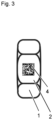
- Figure 3 shows a marked threaded fastener 1 that may be obtained by the method shown in figure 1 or by the method shown in figure 2 .
- the marked threaded fastener 1 is provided with a marking 4 applied to a marking surface 2, wherein the marking surface 2 has a gloss ranging from 5 gloss units to 50 gloss units, inclusive (in particular adjacent to the marking 4).
- y y ⁇ R
Landscapes
- Engineering & Computer Science (AREA)
- General Engineering & Computer Science (AREA)
- Mechanical Engineering (AREA)
- Physics & Mathematics (AREA)
- General Physics & Mathematics (AREA)
- Theoretical Computer Science (AREA)
- Details Of Spanners, Wrenches, And Screw Drivers And Accessories (AREA)
- Other Surface Treatments For Metallic Materials (AREA)
- Slide Fasteners, Snap Fasteners, And Hook Fasteners (AREA)
- Application Of Or Painting With Fluid Materials (AREA)
Abstract
Method for manufacturing a marked threaded fastener (1) comprising,- a providing step, in which a threaded fastener (1) having at least one marking surface (2) is provided,- following the providing step, a roughening step, in which the marking surface (2) is roughened, and- following the roughening step, a marking step, in which a marking (4) is applied to the at least one marking surface (2). Also described is a threaded fastener (1), having a marking surface (2), on top of which at least one coating layer (3) is provided, on top of which at least one marking (4) is provided, wherein the marking surface (2) has gloss ranging from 5 gloss units to 50 gloss units, inclusive.
Description
- The invention relates to a method for manufacturing a marked threaded fastener and to a threaded fastener.
-
EP1171716 B1 describes threaded nuts having 2D barcodes located thereon. - Applying barcodes to threaded fasteners, such as nuts, can pose technical challenges, in particular when the fasteners are steel fasteners, such as carbon steel fasteners or stainless-steel fasteners, provided with a hydrophobic functional coating, such as a friction-modifying coating and/or a corrosion protective coating.
- Laser-marking might damage surfaces, thereby promoting corrosion.
- Throughput of laser-marking might be limited, which might be disadvantageous in view of mass production.
- Ink printing might imply adhesion issues when printing on functional top coatings, resulting in the code marking being not environmentally robust enough for certain applications, in particular outdoor applications
- Markings on bright surfaces might be difficult to read out.
- It is an object to provide a method for manufacturing a fastener attending these and/or other technical challenges, and/or to provide a durable and machine scannable marking solution, in particular for carbon steel or stainless fasteners, in particular suitable for mass production.
- The object is solved by a method according to
claim 1 and by a fastener according to claim 9. Dependent claims describe preferred embodiments of the method. - The invention proposes a method for manufacturing a marked threaded fastener comprising,
- a providing step, in which a threaded fastener having at least one marking surface is provided,
- following the providing step, a roughening step, in which the marking surface is roughened, in particular mechanically roughened, and
- following the roughening step, a marking step, in which a marking is applied to the at least one marking surface, in particular over the at least one coating layer.
- The invention moreover proposes a threaded fastener, preferably manufactured by the method described here, having a marking surface, on top of which at least one coating layer or overcoat layer is provided, on top of which at least one marking is provided, wherein the marking surface has gloss ranging from 5 gloss units (GU) to 50 gloss units (GU), inclusive. Accordingly, the gloss is >= 5 GU and <=50 GU.
- Accordingly, the threaded fastener is explicitly roughened before the code is applied by printing. Increased surface roughness resulting from the roughening step might increasing adhesion of the subsequently applied marking. Additionally or alternatively, said increased surface roughness might entail increased dullness, which in term might improve readability of the marking.
- The roughening step can include roughening the entire surface of the threaded fastener or just parts of said surface. The marking typically extends only over a part of the at least one marking surface, but it might also extend over the entirety of the at least one marking surface. The marking is typically limited to the at least one marking surface, but in other embodiments, the marking might also extend beyond the at least one marking surface, into other surface areas of the threaded fastener.
- The marking surface is the surface on which the marking is intended to be placed. Preferably, the marking surface is a spanner flat, that is a usually generally flat surface intended to be engaged by a spanner or a wrench for imparting torque onto the threaded fastener. Preferably, the threaded fastener has six spanner flats so as to form a hex drive.
- The threaded fastener could for example be a screw. Preferentially, the threaded fastener is a nut having a threaded bore therein. The nut can be placed on the shaft of an expansion anchor.
- In particular, the roughening step can include mechanical roughening, which includes abrasion. Alternatively, chemical roughening, e. g. etching, can be envisaged. In yet another embodiment, the roughening can include applying a material layer, in particular an anti-corrosion material layer, preferably a dull zinc layer, which provides increased roughness as compared to the originally provided marking surface. A dull zinc layer can provide both roughening and corrosion protection.
- It is particularly preferred that the roughening step is a sandblasting step, in which the marking surface is roughened by sandblasting. Sandblasting includes propelling a stream of abrasive material against the marking surface. This may provide for particularly efficient roughening.
- The method might be particularly suitable for steel fasteners, more preferably stainless-steel fasteners.
- It is advantageous that in the roughening step, the marking surface is roughened to have a gloss ranging from 5 gloss units to 50 gloss units, inclusive (i.e. the gloss is >= 5 GU and <=50 GU). This can provide particularly good readability and/or adhesion of overlayers.
- Preferably, the method further comprises, following the roughening step, a coating step, in which the roughened marking surface is coated with at least one coating layer or with at least one overcoat layer, wherein the marking step follows the coating step. This can further improve performance and/or durability. The coating step can include coating the entire surface of the threaded fastener or just parts of said surface.
- The at least one coating layer or at least one overcoat layer is preferably a lubricant layer and/or water-based or solvent-based. Additional coatings can be applied, in addition to the at least one coating layer or at least one overcoat layer. In particular, in the marking step, the marking is applied to the at least one marking surface on top of the at least one coating layer.
- The marking step could imply applying the marking by laser-marking. However, it is particularly preferred that the marking step is a printing step, in which the marking is printed on the at least one marking surface, in particular over the at least one coating layer. Applying the marking by printing, in particular ink jet printing, might allow for particularly high throughput.
- The marking is preferably a barcode, in particular a 2D barcode, for example a QR code or a DMC code.
- Features described here in connection with the fastener can also applied to the method, and vice versa.
- The invention is explained in greater detail below with reference to preferred exemplary embodiments, which are depicted schematically in the accompanying drawings. Individual features of the exemplary embodiments presented below can be implemented either individually or in any combination within the scope of the present invention.
-
Figure 1 shows the step sequence of a first embodiment of a method for manufacturing a marked threaded fastener. The method illustrated infigure 1 is particularly suitable for stainless steel fasteners. The sequence starts with a providingstep 11, in which a threadedfastener 1 having at least one markingsurface 2 is provided. In the shown embodiment, the threadedfastener 1 is, by way of example a nut having an internally threaded bore therein. Alternatively, it could also be a screw having an external thread structure. Preferably, the threadedfastener 1 consists, as already mentioned, of stainless steel. The at least one markingsurface 2 is a spanner flat. By way of example, the provided threadedfastener 1 comprises a total of six spanner flats. - The providing
step 11 is followed by aroughening step 12, in which at least the markingsurface 2 is roughened, preferably mechanically roughened. Alternatively or additionally, chemical roughening of at least the markingsurface 2 could be envisaged in theroughening step 12. In particular, theroughening step 12 is a sandblasting step, in which at least the markingsurface 2 is roughened by means of sandblasting. Roughening implies increasing surface roughness, in particular for increasing adhesion of a coating layer 3 or a marking 4, on the markingsurface 2. In particular, the markingsurface 2 is roughened to have a gloss ranging from 5 gloss units to 50 gloss units, inclusive, in the rougheningstep 12. - Following the roughening
step 12, acoating step 13 is provided, in which the roughened markingsurface 2 is coated with at least one coating layer 3, for example a friction-decreasing or friction-increasing coating layer. Advantageously, the least one coating layer 3 is applied to the entire surface of the threadedfastener 1. - The
coating step 13 is followed by a markingstep 14, in which amarking 4, preferably a barcode, in particular a 2D barcode such as a DMC code or a QR code, is applied to the at least one markingsurface 2. The marking 4 is applied over the at least one coating layer 3 in thecoating step 13, which means that the coating layer 3 is sandwiched between the marking 4 and the markingsurface 2. In particular, the markingstep 14 is a printing step, in which themarking 4 is printed, preferably ink jet printed, on the at least one markingsurface 2. -
Figure 2 shows the step sequence of a second embodiment of a method for manufacturing a marked threaded fastener. The method illustrated infigure 2 is particularly suitable for carbon steel fasteners. The sequence starts with a providingstep 21, in which a threadedfastener 1 having at least one markingsurface 2 is provided. In the shown embodiment, the threadedfastener 1 is, by way of example a nut having an internally threaded bore therein. Alternatively, it could also be a screw having an external thread structure. Preferably, the threadedfastener 1 provided consists, as already mentioned, of carbon steel. The at least one markingsurface 2 is a is a spanner flat. By way of example, the provided threadedfastener 1 comprises a total of six spanner flats. - The providing
step 21 is followed by a rougheningstep 22, in particular a chemical roughening step, in which at least the markingsurface 2, preferably the entire surface of the threadedfastener 1, is covered with an anti-corrosion material layer 7, preferably by means of dull zinc plating. Thus, the anti-corrosion layer 7 is preferably a dull zinc layer. In particular, the anti-corrosion layer 7 provides the markingsurface 2 with a gloss ranging from 5 gloss units to 50 gloss units, inclusive. - Following the
roughening 22, acoating step 23 is provided, in which the dull zinc plated markingsurface 2 is overcoated with at least one overcoat layer 8, for example a friction-decreasing or friction-increasing overcoat layer. Advantageously, the least one overcoat layer 8 is applied to the entire surface of the threadedfastener 1. - The
coating step 23 is followed by a markingstep 24, in which amarking 4, preferably a barcode, in particular a 2D barcode such as a DMC code or a QR code, is applied to the at least one markingsurface 2. The marking 4 is applied over the anti-corrosion layer 7 and over the at least one overcoat layer 8 in thecoating step 13, which means that the coating layer 3 and the at least one overcoat layer 8 are sandwiched between the marking 4 and the markingsurface 2. In particular, the markingstep 14 is a printing step, in which themarking 4 is printed, preferably ink jet printed, on the at least one markingsurface 2. -
Figure 3 shows a marked threadedfastener 1 that may be obtained by the method shown infigure 1 or by the method shown infigure 2 . The marked threadedfastener 1 is provided with a marking 4 applied to a markingsurface 2, wherein the markingsurface 2 has a gloss ranging from 5 gloss units to 50 gloss units, inclusive (in particular adjacent to the marking 4). - The marking 4 can be sized as follows:
For the marking area x, that is the surface area of themarking 4, the following relation can apply:
fastener 1 in mm. - For the aspect ratio y of the
marking 4, which is the ratio of its longer side to its shorter size,

Claims (10)
- Method for manufacturing a marked threaded fastener (1) comprising,- a providing step (11; 21), in which a threaded fastener (1) having at least one marking surface (2) is provided,- following the providing step (11), a roughening step (12; 22), in which the marking surface (2) is roughened, and- following the roughening step (12; 22), a marking step (14; 24), in which a marking (4) is applied to the at least one marking surface (2).
- Method according to claim 1,
characterized in that
the marking surface (2) is a spanner flat. - Method according to any of the preceding claims,
characterized in that
the threaded fastener (1) is a nut having a threaded bore therein. - Method according to any of the preceding claims,
characterized in that
the roughening step (12) is a sandblasting step, in which the marking surface (2) is roughened by sandblasting. - Method according to any of the preceding claims,
characterized in that
the threaded fastener (1) is a stainless-steel fastener. - Method according to any of the preceding claims,
characterized in that
in the roughening step (12; 22), the marking surface (2) is roughened to have a gloss ranging from 5 gloss units to 50 gloss units, inclusive. - Method according to any of the preceding claims,
characterized in that
the method further comprises, following the roughening step (12; 22), a coating step (13; 23), in which the roughened marking surface (2) is coated with at least one coating layer (3) or at least one overcoat layer (8), wherein the marking step (14; 24) follows the coating step (13; 23). - Method according to any of the preceding claims,
characterized in that
the marking step (14; 24) is a printing step, in which the marking (4) is printed on the at least one marking surface (2). - Method according to any of the preceding claims,
characterized in that
the marking (4) is a barcode. - Threaded fastener (1), preferably manufactured by a method according to any of the preceding claims, having a marking surface (2), on top of which at least one coating layer (3) or overcoat layer (8) is provided, on top of which at least one marking (4) is provided, wherein the marking surface (2) has gloss ranging from 5 gloss units to 50 gloss units, inclusive.
Priority Applications (6)
| Application Number | Priority Date | Filing Date | Title |
|---|---|---|---|
| EP22167761.0A EP4261421A1 (en) | 2022-04-12 | 2022-04-12 | Marked threaded fastener manufacture and fastener |
| TW112105020A TW202342892A (en) | 2022-04-12 | 2023-02-13 | Marked threaded fastener manufacture and fastener |
| CN202380023971.5A CN118696175A (en) | 2022-04-12 | 2023-03-28 | Marked threaded fasteners manufacturing and fasteners |
| US18/856,003 US20250188980A1 (en) | 2022-04-12 | 2023-03-28 | Marked Threaded Fastener Manufacture and Fastener |
| EP23713929.0A EP4508339B1 (en) | 2022-04-12 | 2023-03-28 | Marked threaded fastener manufacture and fastener |
| PCT/EP2023/057952 WO2023198443A1 (en) | 2022-04-12 | 2023-03-28 | Marked threaded fastener manufacture and fastener |
Applications Claiming Priority (1)
| Application Number | Priority Date | Filing Date | Title |
|---|---|---|---|
| EP22167761.0A EP4261421A1 (en) | 2022-04-12 | 2022-04-12 | Marked threaded fastener manufacture and fastener |
Publications (1)
| Publication Number | Publication Date |
|---|---|
| EP4261421A1 true EP4261421A1 (en) | 2023-10-18 |
Family
ID=81850725
Family Applications (2)
| Application Number | Title | Priority Date | Filing Date |
|---|---|---|---|
| EP22167761.0A Withdrawn EP4261421A1 (en) | 2022-04-12 | 2022-04-12 | Marked threaded fastener manufacture and fastener |
| EP23713929.0A Active EP4508339B1 (en) | 2022-04-12 | 2023-03-28 | Marked threaded fastener manufacture and fastener |
Family Applications After (1)
| Application Number | Title | Priority Date | Filing Date |
|---|---|---|---|
| EP23713929.0A Active EP4508339B1 (en) | 2022-04-12 | 2023-03-28 | Marked threaded fastener manufacture and fastener |
Country Status (5)
| Country | Link |
|---|---|
| US (1) | US20250188980A1 (en) |
| EP (2) | EP4261421A1 (en) |
| CN (1) | CN118696175A (en) |
| TW (1) | TW202342892A (en) |
| WO (1) | WO2023198443A1 (en) |
Citations (4)
| Publication number | Priority date | Publication date | Assignee | Title |
|---|---|---|---|---|
| EP1171716B1 (en) | 1999-04-16 | 2003-11-19 | Schrauben Betzer GmbH & Co. Kg | Fixing means with machine readable information memory |
| US20070152046A1 (en) * | 2006-01-04 | 2007-07-05 | Chih-Ching Hsieh | Searchable or detectable tool or fastening member or the like |
| CN107655610A (en) * | 2017-08-23 | 2018-02-02 | 中车青岛四方机车车辆股份有限公司 | A kind of intelligent bolt, intelligent bolt calibration system and monitoring system |
| DE102021106817A1 (en) * | 2020-06-18 | 2021-12-23 | Fischerwerke Gmbh & Co. Kg | Screw element |
-
2022
- 2022-04-12 EP EP22167761.0A patent/EP4261421A1/en not_active Withdrawn
-
2023
- 2023-02-13 TW TW112105020A patent/TW202342892A/en unknown
- 2023-03-28 CN CN202380023971.5A patent/CN118696175A/en active Pending
- 2023-03-28 WO PCT/EP2023/057952 patent/WO2023198443A1/en not_active Ceased
- 2023-03-28 EP EP23713929.0A patent/EP4508339B1/en active Active
- 2023-03-28 US US18/856,003 patent/US20250188980A1/en active Pending
Patent Citations (4)
| Publication number | Priority date | Publication date | Assignee | Title |
|---|---|---|---|---|
| EP1171716B1 (en) | 1999-04-16 | 2003-11-19 | Schrauben Betzer GmbH & Co. Kg | Fixing means with machine readable information memory |
| US20070152046A1 (en) * | 2006-01-04 | 2007-07-05 | Chih-Ching Hsieh | Searchable or detectable tool or fastening member or the like |
| CN107655610A (en) * | 2017-08-23 | 2018-02-02 | 中车青岛四方机车车辆股份有限公司 | A kind of intelligent bolt, intelligent bolt calibration system and monitoring system |
| DE102021106817A1 (en) * | 2020-06-18 | 2021-12-23 | Fischerwerke Gmbh & Co. Kg | Screw element |
Also Published As
| Publication number | Publication date |
|---|---|
| TW202342892A (en) | 2023-11-01 |
| EP4508339B1 (en) | 2026-05-06 |
| EP4508339A1 (en) | 2025-02-19 |
| CN118696175A (en) | 2024-09-24 |
| WO2023198443A1 (en) | 2023-10-19 |
| US20250188980A1 (en) | 2025-06-12 |
Similar Documents
| Publication | Publication Date | Title |
|---|---|---|
| EP3676501B1 (en) | Connecting system for friction-increasing connection of components, process for fixing a connecting system to a component and use of a connecting system | |
| US7467556B2 (en) | Thread forming fasteners for ultrasonic load measurement and control | |
| US20120301740A1 (en) | Electro-optical or electromechanical structural element or sliding element | |
| EP4508339B1 (en) | Marked threaded fastener manufacture and fastener | |
| CN104204558A (en) | Self-drilling screw and use thereof | |
| EP3191260B1 (en) | Tapered lobular driver and fastener | |
| US20150000479A1 (en) | Tapered lobular driver and fastener | |
| US20190093700A1 (en) | Rivetless fastener and installation tool | |
| Brezinová et al. | Abrasive Blast Cleaning and Its Application | |
| KR20140123094A (en) | Surface | |
| US20080248214A1 (en) | Method of forming an oxide coating with dimples on its surface | |
| SE513219C2 (en) | Wear surface and process for making the same | |
| US20060210802A1 (en) | Plate material and manufacturing method thereof | |
| EP3453899A1 (en) | Threaded fastener and assembly tool | |
| Momber et al. | The Performance of AA6082 Aluminum in Simulated Marine Environments after Blast-Cleaning with Recycled Glass Grit | |
| CN2586547Y (en) | Duromer coated roller | |
| US20260117813A1 (en) | Securing thin materials with quick fastening assemblies | |
| CN108817842B (en) | Method for repairing anti-side-rolling torsion bar shaft after galvanic corrosion | |
| US8322280B2 (en) | Device for applying information onto a surface of an aircraft | |
| Connelly | Failures of Mechanical Fasteners | |
| EP2828885B1 (en) | Pressure transfer plate for pressure transfer of a bonding pressure | |
| CN108488182A (en) | A kind of coiled hair cross Self Drilling Screws and its preparation process improving degree of being completely embedded | |
| JP2004268111A (en) | Method for removing foreign matter on tension roll of temper rolling mill | |
| CN108180206A (en) | A kind of hexagonal washer STAINLESS STEEL SELF DRILLING SCREWS and its preparation process | |
| CN108180205A (en) | A kind of coiled hair cross STAINLESS STEEL SELF DRILLING SCREWS and its preparation process |
Legal Events
| Date | Code | Title | Description |
|---|---|---|---|
| PUAI | Public reference made under article 153(3) epc to a published international application that has entered the european phase |
Free format text: ORIGINAL CODE: 0009012 |
|
| STAA | Information on the status of an ep patent application or granted ep patent |
Free format text: STATUS: THE APPLICATION HAS BEEN PUBLISHED |
|
| AK | Designated contracting states |
Kind code of ref document: A1 Designated state(s): AL AT BE BG CH CY CZ DE DK EE ES FI FR GB GR HR HU IE IS IT LI LT LU LV MC MK MT NL NO PL PT RO RS SE SI SK SM TR |
|
| STAA | Information on the status of an ep patent application or granted ep patent |
Free format text: STATUS: THE APPLICATION IS DEEMED TO BE WITHDRAWN |
|
| 18D | Application deemed to be withdrawn |
Effective date: 20240419 |