EP4261420A1 - Hydraulic work machine - Google Patents
Hydraulic work machine Download PDFInfo
- Publication number
- EP4261420A1 EP4261420A1 EP21924862.2A EP21924862A EP4261420A1 EP 4261420 A1 EP4261420 A1 EP 4261420A1 EP 21924862 A EP21924862 A EP 21924862A EP 4261420 A1 EP4261420 A1 EP 4261420A1
- Authority
- EP
- European Patent Office
- Prior art keywords
- control
- output
- input
- manipulation
- parameter
- Prior art date
- Legal status (The legal status is an assumption and is not a legal conclusion. Google has not performed a legal analysis and makes no representation as to the accuracy of the status listed.)
- Pending
Links
Images


Classifications
-
- E—FIXED CONSTRUCTIONS
- E02—HYDRAULIC ENGINEERING; FOUNDATIONS; SOIL SHIFTING
- E02F—DREDGING; SOIL-SHIFTING
- E02F9/00—Component parts of dredgers or soil-shifting machines, not restricted to one of the kinds covered by groups E02F3/00 - E02F7/00
- E02F9/20—Drives; Control devices
- E02F9/22—Hydraulic or pneumatic drives
- E02F9/2221—Control of flow rate; Load sensing arrangements
- E02F9/2225—Control of flow rate; Load sensing arrangements using pressure-compensating valves
- E02F9/2228—Control of flow rate; Load sensing arrangements using pressure-compensating valves including an electronic controller
-
- E—FIXED CONSTRUCTIONS
- E02—HYDRAULIC ENGINEERING; FOUNDATIONS; SOIL SHIFTING
- E02F—DREDGING; SOIL-SHIFTING
- E02F9/00—Component parts of dredgers or soil-shifting machines, not restricted to one of the kinds covered by groups E02F3/00 - E02F7/00
- E02F9/20—Drives; Control devices
- E02F9/22—Hydraulic or pneumatic drives
- E02F9/2221—Control of flow rate; Load sensing arrangements
-
- E—FIXED CONSTRUCTIONS
- E02—HYDRAULIC ENGINEERING; FOUNDATIONS; SOIL SHIFTING
- E02F—DREDGING; SOIL-SHIFTING
- E02F9/00—Component parts of dredgers or soil-shifting machines, not restricted to one of the kinds covered by groups E02F3/00 - E02F7/00
- E02F9/20—Drives; Control devices
- E02F9/22—Hydraulic or pneumatic drives
- E02F9/2221—Control of flow rate; Load sensing arrangements
- E02F9/2232—Control of flow rate; Load sensing arrangements using one or more variable displacement pumps
- E02F9/2235—Control of flow rate; Load sensing arrangements using one or more variable displacement pumps including an electronic controller
-
- E—FIXED CONSTRUCTIONS
- E02—HYDRAULIC ENGINEERING; FOUNDATIONS; SOIL SHIFTING
- E02F—DREDGING; SOIL-SHIFTING
- E02F9/00—Component parts of dredgers or soil-shifting machines, not restricted to one of the kinds covered by groups E02F3/00 - E02F7/00
- E02F9/20—Drives; Control devices
- E02F9/22—Hydraulic or pneumatic drives
- E02F9/2278—Hydraulic circuits
- E02F9/2285—Pilot-operated systems
-
- E—FIXED CONSTRUCTIONS
- E02—HYDRAULIC ENGINEERING; FOUNDATIONS; SOIL SHIFTING
- E02F—DREDGING; SOIL-SHIFTING
- E02F9/00—Component parts of dredgers or soil-shifting machines, not restricted to one of the kinds covered by groups E02F3/00 - E02F7/00
- E02F9/20—Drives; Control devices
- E02F9/22—Hydraulic or pneumatic drives
- E02F9/2278—Hydraulic circuits
- E02F9/2296—Systems with a variable displacement pump
-
- F—MECHANICAL ENGINEERING; LIGHTING; HEATING; WEAPONS; BLASTING
- F15—FLUID-PRESSURE ACTUATORS; HYDRAULICS OR PNEUMATICS IN GENERAL
- F15B—SYSTEMS ACTING BY MEANS OF FLUIDS IN GENERAL; FLUID-PRESSURE ACTUATORS, e.g. SERVOMOTORS; DETAILS OF FLUID-PRESSURE SYSTEMS, NOT OTHERWISE PROVIDED FOR
- F15B21/00—Common features of fluid actuator systems; Fluid-pressure actuator systems or details thereof, not covered by any other group of this subclass
- F15B21/08—Servomotor systems incorporating electrically operated control means
- F15B21/087—Control strategy, e.g. with block diagram
-
- F—MECHANICAL ENGINEERING; LIGHTING; HEATING; WEAPONS; BLASTING
- F15—FLUID-PRESSURE ACTUATORS; HYDRAULICS OR PNEUMATICS IN GENERAL
- F15B—SYSTEMS ACTING BY MEANS OF FLUIDS IN GENERAL; FLUID-PRESSURE ACTUATORS, e.g. SERVOMOTORS; DETAILS OF FLUID-PRESSURE SYSTEMS, NOT OTHERWISE PROVIDED FOR
- F15B2211/00—Circuits for servomotor systems
- F15B2211/20—Fluid pressure source, e.g. accumulator or variable axial piston pump
- F15B2211/205—Systems with pumps
- F15B2211/2053—Type of pump
- F15B2211/20546—Type of pump variable capacity
-
- F—MECHANICAL ENGINEERING; LIGHTING; HEATING; WEAPONS; BLASTING
- F15—FLUID-PRESSURE ACTUATORS; HYDRAULICS OR PNEUMATICS IN GENERAL
- F15B—SYSTEMS ACTING BY MEANS OF FLUIDS IN GENERAL; FLUID-PRESSURE ACTUATORS, e.g. SERVOMOTORS; DETAILS OF FLUID-PRESSURE SYSTEMS, NOT OTHERWISE PROVIDED FOR
- F15B2211/00—Circuits for servomotor systems
- F15B2211/30—Directional control
- F15B2211/305—Directional control characterised by the type of valves
- F15B2211/30525—Directional control valves, e.g. 4/3-directional control valve
-
- F—MECHANICAL ENGINEERING; LIGHTING; HEATING; WEAPONS; BLASTING
- F15—FLUID-PRESSURE ACTUATORS; HYDRAULICS OR PNEUMATICS IN GENERAL
- F15B—SYSTEMS ACTING BY MEANS OF FLUIDS IN GENERAL; FLUID-PRESSURE ACTUATORS, e.g. SERVOMOTORS; DETAILS OF FLUID-PRESSURE SYSTEMS, NOT OTHERWISE PROVIDED FOR
- F15B2211/00—Circuits for servomotor systems
- F15B2211/30—Directional control
- F15B2211/31—Directional control characterised by the positions of the valve element
- F15B2211/3144—Directional control characterised by the positions of the valve element the positions being continuously variable, e.g. as realised by proportional valves
-
- F—MECHANICAL ENGINEERING; LIGHTING; HEATING; WEAPONS; BLASTING
- F15—FLUID-PRESSURE ACTUATORS; HYDRAULICS OR PNEUMATICS IN GENERAL
- F15B—SYSTEMS ACTING BY MEANS OF FLUIDS IN GENERAL; FLUID-PRESSURE ACTUATORS, e.g. SERVOMOTORS; DETAILS OF FLUID-PRESSURE SYSTEMS, NOT OTHERWISE PROVIDED FOR
- F15B2211/00—Circuits for servomotor systems
- F15B2211/30—Directional control
- F15B2211/32—Directional control characterised by the type of actuation
- F15B2211/327—Directional control characterised by the type of actuation electrically or electronically
-
- F—MECHANICAL ENGINEERING; LIGHTING; HEATING; WEAPONS; BLASTING
- F15—FLUID-PRESSURE ACTUATORS; HYDRAULICS OR PNEUMATICS IN GENERAL
- F15B—SYSTEMS ACTING BY MEANS OF FLUIDS IN GENERAL; FLUID-PRESSURE ACTUATORS, e.g. SERVOMOTORS; DETAILS OF FLUID-PRESSURE SYSTEMS, NOT OTHERWISE PROVIDED FOR
- F15B2211/00—Circuits for servomotor systems
- F15B2211/30—Directional control
- F15B2211/35—Directional control combined with flow control
- F15B2211/351—Flow control by regulating means in feed line, i.e. meter-in control
-
- F—MECHANICAL ENGINEERING; LIGHTING; HEATING; WEAPONS; BLASTING
- F15—FLUID-PRESSURE ACTUATORS; HYDRAULICS OR PNEUMATICS IN GENERAL
- F15B—SYSTEMS ACTING BY MEANS OF FLUIDS IN GENERAL; FLUID-PRESSURE ACTUATORS, e.g. SERVOMOTORS; DETAILS OF FLUID-PRESSURE SYSTEMS, NOT OTHERWISE PROVIDED FOR
- F15B2211/00—Circuits for servomotor systems
- F15B2211/30—Directional control
- F15B2211/35—Directional control combined with flow control
- F15B2211/353—Flow control by regulating means in return line, i.e. meter-out control
-
- F—MECHANICAL ENGINEERING; LIGHTING; HEATING; WEAPONS; BLASTING
- F15—FLUID-PRESSURE ACTUATORS; HYDRAULICS OR PNEUMATICS IN GENERAL
- F15B—SYSTEMS ACTING BY MEANS OF FLUIDS IN GENERAL; FLUID-PRESSURE ACTUATORS, e.g. SERVOMOTORS; DETAILS OF FLUID-PRESSURE SYSTEMS, NOT OTHERWISE PROVIDED FOR
- F15B2211/00—Circuits for servomotor systems
- F15B2211/60—Circuit components or control therefor
- F15B2211/63—Electronic controllers
- F15B2211/6303—Electronic controllers using input signals
- F15B2211/632—Electronic controllers using input signals representing a flow rate
- F15B2211/6326—Electronic controllers using input signals representing a flow rate the flow rate being an output member flow rate
-
- F—MECHANICAL ENGINEERING; LIGHTING; HEATING; WEAPONS; BLASTING
- F15—FLUID-PRESSURE ACTUATORS; HYDRAULICS OR PNEUMATICS IN GENERAL
- F15B—SYSTEMS ACTING BY MEANS OF FLUIDS IN GENERAL; FLUID-PRESSURE ACTUATORS, e.g. SERVOMOTORS; DETAILS OF FLUID-PRESSURE SYSTEMS, NOT OTHERWISE PROVIDED FOR
- F15B2211/00—Circuits for servomotor systems
- F15B2211/60—Circuit components or control therefor
- F15B2211/63—Electronic controllers
- F15B2211/6303—Electronic controllers using input signals
- F15B2211/6336—Electronic controllers using input signals representing a state of the output member, e.g. position, speed or acceleration
-
- F—MECHANICAL ENGINEERING; LIGHTING; HEATING; WEAPONS; BLASTING
- F15—FLUID-PRESSURE ACTUATORS; HYDRAULICS OR PNEUMATICS IN GENERAL
- F15B—SYSTEMS ACTING BY MEANS OF FLUIDS IN GENERAL; FLUID-PRESSURE ACTUATORS, e.g. SERVOMOTORS; DETAILS OF FLUID-PRESSURE SYSTEMS, NOT OTHERWISE PROVIDED FOR
- F15B2211/00—Circuits for servomotor systems
- F15B2211/60—Circuit components or control therefor
- F15B2211/63—Electronic controllers
- F15B2211/6303—Electronic controllers using input signals
- F15B2211/6346—Electronic controllers using input signals representing a state of input means, e.g. joystick position
-
- F—MECHANICAL ENGINEERING; LIGHTING; HEATING; WEAPONS; BLASTING
- F15—FLUID-PRESSURE ACTUATORS; HYDRAULICS OR PNEUMATICS IN GENERAL
- F15B—SYSTEMS ACTING BY MEANS OF FLUIDS IN GENERAL; FLUID-PRESSURE ACTUATORS, e.g. SERVOMOTORS; DETAILS OF FLUID-PRESSURE SYSTEMS, NOT OTHERWISE PROVIDED FOR
- F15B2211/00—Circuits for servomotor systems
- F15B2211/60—Circuit components or control therefor
- F15B2211/665—Methods of control using electronic components
-
- F—MECHANICAL ENGINEERING; LIGHTING; HEATING; WEAPONS; BLASTING
- F15—FLUID-PRESSURE ACTUATORS; HYDRAULICS OR PNEUMATICS IN GENERAL
- F15B—SYSTEMS ACTING BY MEANS OF FLUIDS IN GENERAL; FLUID-PRESSURE ACTUATORS, e.g. SERVOMOTORS; DETAILS OF FLUID-PRESSURE SYSTEMS, NOT OTHERWISE PROVIDED FOR
- F15B2211/00—Circuits for servomotor systems
- F15B2211/60—Circuit components or control therefor
- F15B2211/665—Methods of control using electronic components
- F15B2211/6652—Control of the pressure source, e.g. control of the swash plate angle
-
- F—MECHANICAL ENGINEERING; LIGHTING; HEATING; WEAPONS; BLASTING
- F15—FLUID-PRESSURE ACTUATORS; HYDRAULICS OR PNEUMATICS IN GENERAL
- F15B—SYSTEMS ACTING BY MEANS OF FLUIDS IN GENERAL; FLUID-PRESSURE ACTUATORS, e.g. SERVOMOTORS; DETAILS OF FLUID-PRESSURE SYSTEMS, NOT OTHERWISE PROVIDED FOR
- F15B2211/00—Circuits for servomotor systems
- F15B2211/60—Circuit components or control therefor
- F15B2211/665—Methods of control using electronic components
- F15B2211/6654—Flow rate control
-
- F—MECHANICAL ENGINEERING; LIGHTING; HEATING; WEAPONS; BLASTING
- F15—FLUID-PRESSURE ACTUATORS; HYDRAULICS OR PNEUMATICS IN GENERAL
- F15B—SYSTEMS ACTING BY MEANS OF FLUIDS IN GENERAL; FLUID-PRESSURE ACTUATORS, e.g. SERVOMOTORS; DETAILS OF FLUID-PRESSURE SYSTEMS, NOT OTHERWISE PROVIDED FOR
- F15B2211/00—Circuits for servomotor systems
- F15B2211/60—Circuit components or control therefor
- F15B2211/665—Methods of control using electronic components
- F15B2211/6658—Control using different modes, e.g. four-quadrant-operation, working mode and transportation mode
-
- F—MECHANICAL ENGINEERING; LIGHTING; HEATING; WEAPONS; BLASTING
- F15—FLUID-PRESSURE ACTUATORS; HYDRAULICS OR PNEUMATICS IN GENERAL
- F15B—SYSTEMS ACTING BY MEANS OF FLUIDS IN GENERAL; FLUID-PRESSURE ACTUATORS, e.g. SERVOMOTORS; DETAILS OF FLUID-PRESSURE SYSTEMS, NOT OTHERWISE PROVIDED FOR
- F15B2211/00—Circuits for servomotor systems
- F15B2211/70—Output members, e.g. hydraulic motors or cylinders or control therefor
- F15B2211/75—Control of speed of the output member
-
- F—MECHANICAL ENGINEERING; LIGHTING; HEATING; WEAPONS; BLASTING
- F15—FLUID-PRESSURE ACTUATORS; HYDRAULICS OR PNEUMATICS IN GENERAL
- F15B—SYSTEMS ACTING BY MEANS OF FLUIDS IN GENERAL; FLUID-PRESSURE ACTUATORS, e.g. SERVOMOTORS; DETAILS OF FLUID-PRESSURE SYSTEMS, NOT OTHERWISE PROVIDED FOR
- F15B2211/00—Circuits for servomotor systems
- F15B2211/70—Output members, e.g. hydraulic motors or cylinders or control therefor
- F15B2211/76—Control of force or torque of the output member
- F15B2211/761—Control of a negative load, i.e. of a load generating hydraulic energy
-
- F—MECHANICAL ENGINEERING; LIGHTING; HEATING; WEAPONS; BLASTING
- F15—FLUID-PRESSURE ACTUATORS; HYDRAULICS OR PNEUMATICS IN GENERAL
- F15B—SYSTEMS ACTING BY MEANS OF FLUIDS IN GENERAL; FLUID-PRESSURE ACTUATORS, e.g. SERVOMOTORS; DETAILS OF FLUID-PRESSURE SYSTEMS, NOT OTHERWISE PROVIDED FOR
- F15B2211/00—Circuits for servomotor systems
- F15B2211/80—Other types of control related to particular problems or conditions
- F15B2211/87—Detection of failures
-
- F—MECHANICAL ENGINEERING; LIGHTING; HEATING; WEAPONS; BLASTING
- F15—FLUID-PRESSURE ACTUATORS; HYDRAULICS OR PNEUMATICS IN GENERAL
- F15B—SYSTEMS ACTING BY MEANS OF FLUIDS IN GENERAL; FLUID-PRESSURE ACTUATORS, e.g. SERVOMOTORS; DETAILS OF FLUID-PRESSURE SYSTEMS, NOT OTHERWISE PROVIDED FOR
- F15B2211/00—Circuits for servomotor systems
- F15B2211/80—Other types of control related to particular problems or conditions
- F15B2211/875—Control measures for coping with failures
Definitions
- the present invention relates to a hydraulic working machine including a control device that controls a controlled object.
- An improvement in the operability of a manipulation by an operator in a hydraulic working machine, such as a hydraulic excavator, leads to an improvement in a work efficiency on a worksite.
- Patent Literature 1 discloses a hydraulic actuator control device including an electric current controller.
- the hydraulic actuator control device supplies, to a solenoid proportional flow rate control valve, an electric current larger than a target electric current corresponding to a manipulation amount of a manipulation lever for only a predetermined short time period at a start of a driving manipulation from a neutral position with an aim of improving the operability by reducing response delay in activating the hydraulic actuator from a suspension state.
- Patent Literature 2 discloses a construction machine including a controller that outputs a command current for driving a solenoid proportional valve in response to a manipulation signal from a manipulation device.
- the controller has a correction function to correct the command current in such a manner that the command current is higher than a target current corresponding to a manipulation amount of a manipulation device for a preset predetermined time at a time of starting to manipulate the manipulation device from a neutral position thereof with an aim of ensuring an initial response that varies in accordance with a type of hydraulic actuator.
- Patent Literature 3 discloses a hydraulic working machine including a control device to improve initial responsiveness of a hydraulic actuator while ensuring energy saving performance.
- the control device modifies a pump target flow rate by adding a predetermined modification flow rate, which is larger than a pump minimum flow rate of a first hydraulic pump, to a pump target flow rate for a period to a lapse of a predetermined modification time after a manipulation of a first manipulation lever from a neutral position thereof.
- Patent Literature 4 discloses a construction machine including a controller for keeping a specific relationship regardless of a change in a reach, the specific relationship being a relationship between a boom manipulation amount and a rising or lowering amount of an attachment leading end in a rising or lowering operation of the attachment leading end to rise or to be lowered.
- the controller modifies, in accordance with the reach, a pump flow rate determined by a boom raising manipulation amount, specifically, the controller decreases the pump flow rate when the reach is long and increases the pump flow rate when the reach is short.
- a secondary pressure of a proportional valve provided on a boom lowering pilot line is modified in accordance with the reach to thereby reduce an opening degree of a control valve when the reach is long and increase the opening degree when the reach is short.
- input and output characteristics of a controlled object including: a proportional valve that receives an input of an instruction from a control device; and an actuator that causes a movable part, such as a boom, to operate may largely fluctuate due to, for example, replacement of a leading end attachment, an aging deterioration of a component of a working machine, or other factor.
- the controller or control device disclosed in each of Patent Literatures 1 to 4 does not consider such a fluctuation in the input and output characteristics of the controlled object.
- a control output being an output of the actuator thus fails to be suited to a manipulation amount in a case of a large fluctuation in the input and output characteristics of the controlled object.
- a controlled object to be targeted in a power running operation like a boom rising operation differs from a controlled object to be targeted in a non-power running operation like a boom lowering operation.
- a rate of the aging deterioration varies depending on each component constituting the corresponding controlled object.
- each of the power running operation and the non-power running operation of the movable part is required to approximate to an ideal operation suited to the manipulation amount even in a case of a large fluctuation in the input and output characteristics of the controlled object.
- the present invention has been achieved to solve the aforementioned drawbacks with an aim of providing a hydraulic working machine that allows each of a power running operation and a non-power running operation to approximate to an ideal operation suited to a manipulation amount even in a case of a large fluctuation in input and output characteristics of a controlled object.
- a hydraulic working machine includes: a support body; a movable part that is shiftable relative to the support body; a hydraulic pump that discharges hydraulic fluid; an actuator that receives a supply of the hydraulic fluid to cause the movable part to operate; a control valve that is located between the hydraulic pump and the actuator, and opens and closes to change a flow rate of the hydraulic fluid to be supplied to the actuator; a manipulation device that receives a manipulation for an operation of the movable part; an operation determinator that determines whether the operation of the movable part performed in response to the manipulation received by the manipulation device is a power running operation of the movable part to operate against a load acting on the movable part or a non-power running operation of the movable part to operate in a direction of the load acting on the movable part; a pump control device that regulates a discharge rate of the hydraulic pump; a valve control device that regulates an opening degree of the control valve; and an output detector that detects a control output being an output
- the pump control device has: a pump instruction calculator that calculates, by using a manipulation amount of the manipulation and at least one pump control parameter, a control instruction of causing a controlled object including the hydraulic pump and the actuator to operate, and inputs the calculated control instruction to the controlled object; a pump control ideal output calculator that calculates an ideal output of the actuator, the ideal output being associated with the manipulation amount of the manipulation; and a pump control parameter adjuster that adjusts the at least one pump control parameter to reduce a difference between the control output and the ideal output when the operation of the movable part is the power running operation.
- the valve control device has: a valve instruction calculator that calculates, by using the manipulation amount of the manipulation and at least one valve control parameter, a control instruction of causing a controlled object including the control valve and the actuator to operate, and inputs the calculated control instruction to the controlled object; a valve control ideal output calculator that calculates an ideal output of the actuator, the ideal output being associated with the manipulation amount of the manipulation; and a valve control parameter adjuster that adjusts the at least one valve control parameter to reduce a difference between the control output and the ideal output when the operation of the movable part is the non-power running operation.
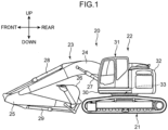
- Fig. 1 is a side view of a hydraulic excavator 20 which is an example of a hydraulic working machine according to an embodiment.
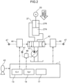
- Fig. 2 is a diagram showing an example of a hydraulic circuit and a control unit included in the hydraulic excavator 20.
- the hydraulic excavator 20 includes: a lower traveling body 21 of a self-running type; an upper slewing body 22 slewably supported on the lower traveling body 21; a working device 23; a plurality of hydraulic actuators; a plurality of hydraulic pumps; a pilot pump 47; a plurality of control valves; a plurality of manipulation devices; a plurality of proportional valves; an output detector 12 (see Fig. 3 ); and a control unit 1.
- the upper slewing body 22 includes an upper frame 30 slewably supported on the lower traveling body 21, a cabin 31 supported on the upper frame 30, and a counterweight 32 disposed in the rear of the cabin 31.
- the lower traveling body 21 and the upper slewing body 22 serve as an example of a support body.
- the working device 23 includes a boom 24 tiltably supported on the upper frame 30, an arm 25 rotatably supported on a distal end of the boom 24, and a bucket 26 rotatably supported on a distal end of the arm 25.
- the boom 24 serves as an example of the movable part.
- the hydraulic actuators include a boom cylinder 27, an arm cylinder 28, a bucket cylinder 29, and a slewing motor 33.
- Each of the hydraulic pumps is a hydraulic pump for supplying hydraulic fluid to at least one of the hydraulic actuators.
- the hydraulic pumps include a hydraulic pump 41 of a variable displacement type shown in Fig. 2 .
- the pilot pump 47 is a hydraulic pump for supplying a pilot pressure to each of the control valves.
- Each of the hydraulic pumps and the pilot pump 47 is driven by an unillustrated engine.
- Fig. 2 representatively shows a circuit of causing the boom cylinder 27 to operate without illustrations of circuits of respectively causing the arm cylinder 28, the bucket cylinder 29, and the slewing motor 33 to operate.
- Each of the circuits of respectively causing the arm cylinder 28, the bucket cylinder 29, and the slewing motor 33 to operate has the same structure as the circuit of causing the boom cylinder 27 shown in Fig. 2 to operate.
- the boom cylinder 27 is a hydraulic cylinder that receives a supply of the hydraulic fluid from the hydraulic pump 41 shown in Fig. 2 to cause the boom 24 to perform a rising or lowering operation.
- the boom cylinder 27 includes a cylinder tube having a proximal end rotatably attached to the upper frame 30 of the upper slewing body 22, and the boom cylinder 27 includes a piston rod having a distal end rotatably attached to the boom 24.
- the boom cylinder 27 has a rod chamber 27R and a head chamber 27H.
- the arm cylinder 28 is a hydraulic cylinder that receives a supply of the hydraulic fluid from any one of the hydraulic pumps to cause the arm 25 to rotate.
- the bucket cylinder 29 is a hydraulic cylinder that receives a supply of the hydraulic fluid from any one of the hydraulic pumps to cause the bucket 26 to rotate.
- the slewing motor 33 is a hydraulic motor that receives a supply of the hydraulic fluid from any one of the hydraulic pumps to cause the upper frame 30 of the upper slewing body 22 to slew to the lower traveling body 21.
- the control valves include a boom control valve 42 shown in Fig. 2 , an unillustrated arm control valve, an unillustrated bucket control valve, and an unillustrated slewing control valve.
- Each of the control valves has a spool and a pair of pilot ports for receiving the pilot pressure from the pilot pump 47.
- the boom control valve 42 is located between the hydraulic pump 41 and the boom cylinder 27, and opens and closes to change a direction and a flow rate of the hydraulic fluid to be supplied to the boom cylinder 27.
- the arm control valve is located between any one of the hydraulic pumps and the arm cylinder 28, and opens and closes to change a direction and a flow rate of the hydraulic fluid to be supplied to the arm cylinder 28.
- the bucket control valve is located between any one of the hydraulic pumps and the bucket cylinder 29, and opens and closes to change a direction and a flow rate of the hydraulic fluid to be supplied to the bucket cylinder 29.
- the slewing control valve is located between any one of the hydraulic pumps and the slewing motor 33, and opens and closes to change a direction and a flow rate of the hydraulic fluid to be supplied to the slewing motor 33.
- the manipulation devices include a boom manipulation device 43 (see Fig 2 ) that receives a manipulation for an operation of the boom 24, an unillustrated arm manipulation device that receives a manipulation for an operation of the arm 25, an unillustrated bucket manipulation device that receives a manipulation for an operation of the bucket 26, and an unillustrated slewing manipulation device for a slewing operation of the upper slewing body 22 to the lower traveling body 21.
- Each of the manipulation devices has a manipulation lever for allowing an operator to give a manipulation thereto.
- Each of the manipulation devices represents an electric lever device that outputs an instruction signal (electric signal) corresponding to a manipulation received by the manipulation lever and a manipulation amount thereof. The output instruction signal is input to the control unit 1.
- the boom manipulation device 43 is configured to receive a boom raising manipulation for causing the boom 24 to perform a boom rising operation and a boom lowering manipulation for causing the boom 24 to perform a boom lowering operation.
- the boom rising operation is an operation of the boom 24 that the distal end of the boom 24 rises away from the ground
- the boom lowering operation is an operation of the boom 24 that the distal end of the boom 24 approaches the ground.
- the boom rising operation requires a regulation of a discharge rate of the hydraulic pump 41 to shift the working device 23 in a direction opposite to a direction of the gravity as shown in Fig. 2 .
- the boom rising operation serves as an example of a power running operation of the boom 24 to operate against a load acting on the working device 23 including the boom 24.
- the boom lowering operation requires a regulation of an opening degree of the boom control valve 42 to shift the working device 23 in the direction of the gravity acting on the working device 23 at a desired operation speed.
- the boom lowering operation serves as an example of a non-power running operation of the boom 24 to operate in a direction of the load acting on the working device 23 including the boom 24.
- the boom raising manipulation serves as an example of an power running manipulation
- the boom lowering manipulation serves as an example of a non-power running manipulation (regenerative manipulation).
- the boom manipulation device 43 When the boom manipulation device 43 receives the boom raising manipulation, the boom manipulation device inputs, to the control unit 1, a boom raising instruction signal corresponding to the boom raising manipulation and a manipulation amount thereof.
- the boom manipulation device 43 receives the boom lowering manipulation, the boom manipulation device inputs, to the control unit 1, a boom lowering instruction signal corresponding to the boom lowering manipulation and a manipulation amount thereof.
- the basic configuration and function of each of the arm manipulation device, the bucket manipulation device, and the slewing manipulation device are the same as those of the boom manipulation device 43, and thus detailed description therefor is omitted.
- Each of the proportional valves reduces a pressure of the hydraulic fluid from the pilot pump 47 and outputs the hydraulic fluid having the reduced pressure in response to a control instruction input from the control unit 1.
- Each of the proportional valves is formed of, for example, a solenoid proportional valve.
- the proportional valves include a pair of boom proportional valves 44, 45, a pair of arm proportional valves (not shown), a pair of bucket proportional valves (not shown), and a pair of slewing proportional valves (not shown), and a pump proportional valve 46.
- each of the two boom proportional valves 44, 45 reduces a pressure of the hydraulic fluid from the pilot pump 47 in response to a control instruction (instruction electric current) input from the control unit 1, and outputs a pilot pressure responsive to the control instruction to the boom control valve 42.
- the pair of boom proportional valves 44, 45 is provided on a pair of pilot lines connecting the pilot pump 47 and the pair of pilot ports of the boom control valve 42 to each other.
- a control instruction is input from the control unit 1 to the boom proportional valve 44.
- the boom proportional valve 44 generates a pilot pressure responsive to the control instruction, and the generated pilot pressure is supplied to one of the pilot ports of the boom control valve 42, i.e., the left port of the boom control valve 42 in Fig. 2 .
- the spool of the boom control valve 42 shifts in a shift amount (which is a shift amount from a neutral position) corresponding to the supplied pilot pressure.
- the boom control valve 42 has an opening degree (opening amount) regulated to correspond to the shift amount so as to permit the hydraulic fluid discharged from the hydraulic pump 41 to be supplied to the rod chamber 27R of the boom cylinder 27 at a flow rate corresponding to the shift amount, and permit the hydraulic fluid to be discharged from the head chamber 27H and return to the tank.
- a control instruction is input from the control unit 1 to the boom proportional valve 45.
- the control unit 1 outputs, as the control instruction, an instructive value in accordance with a manipulation amount of the boom raising manipulation.
- the boom proportional valve 45 generates a pilot pressure responsive to the control instruction, and the generated pilot pressure is supplied to the other of the pilot ports of the boom control valve 42, i.e., the right port of the boom control valve 42 in Fig. 2 .
- the spool of the boom control valve 42 shifts in a shift amount (which is a shift amount from a neutral position) corresponding to the supplied pilot pressure.
- the boom control valve 42 has an opening degree (opening amount) regulated to correspond to the shift amount so as to permit the hydraulic fluid discharged from the hydraulic pump 41 to be supplied to the head chamber 27H of the boom cylinder 27 at a flow rate corresponding to the shift amount, and permit the hydraulic fluid to be discharged from the rod chamber 27R and return to the tank.
- Each of the two arm proportional valves reduces a pressure of the hydraulic fluid from the pilot pump 47 in response to a control instruction input from the control unit 1, and outputs a pilot pressure responsive to the control instruction to the arm control valve.
- Each of the two bucket proportional valves reduces a pressure of the hydraulic fluid from the pilot pump 47 in response to a control instruction input from the control unit 1, and outputs a pilot pressure responsive to the control instruction to the bucket control valve.
- Each of the two slewing proportional valves reduces a pressure of the hydraulic fluid from the pilot pump 47 in response to a control instruction input from the control unit 1, and outputs a pilot pressure responsive to the control instruction to the slewing control valve.
- the basic configuration and function of the proportional valves are the same as those of the boom proportional valves 44, 45, and thus detailed description therefor is omitted.
- the pump proportional valve 46 reduces a pressure of the hydraulic fluid from a specific hydraulic pump, e.g., the pilot pump 47, in response to a control instruction (instruction electric current) output from the control unit 1, and outputs an operation pressure responsive to the control instruction to the hydraulic pump 41.
- the pump proportional valve 46 is provided on a pump line connecting the pilot pump 47 and the hydraulic pump 41 to each other.
- a capacity (tilt angle) of the hydraulic pump 41 is adjusted to a capacity (tilt angle) corresponding to the operation pressure. In this manner, the discharge rate of the hydraulic pump 41 is regulated.
- the control unit 1 includes a pump control device 14 that regulates a discharge rate of the hydraulic pump 41, a valve control device 13 that regulates an opening degree of the boom control valve 42, and an operation determinator 17 that determines an operation of the boom 24.
- Fig. 3 is a block diagram showing an example of a control device included in the control unit 1.
- the control device shown in Fig. 3 represents a configuration of each of the pump control device 14 and the valve control device 13.
- the output detector 12 shown in Fig. 3 detects a control output y(k) being an output of the boom cylinder 27.
- the control output y(k) of the boom cylinder 27 may include, for example, an operation speed of the boom cylinder 27 or a physical quantity corresponding to the operation speed of the boom cylinder 27.
- the physical quantity corresponding to the operation speed may be, for example, a flow rate of the hydraulic fluid being supplied to the boom cylinder 27, may be a flow rate of the hydraulic fluid being discharged from the boom cylinder 27, or may be an operation speed of the boom 24 in a rising or lowering operation of the boom 24.
- the output detector 12 may include a speed sensor for detecting the operation speed of the boom cylinder 27, a flow rate sensor for detecting the flow rate of the hydraulic fluid being supplied to the boom cylinder 27 or the flow rate of the hydraulic fluid being discharged from the boom cylinder 27, or a speed sensor for detecting the operation speed of the boom 24 in the rising or lowering operation of the boom 24.
- the operation determinator 17 shown in Fig. 2 determines whether an operation of the boom 24 performed in response to a manipulation received by the boom manipulation device 43 is the boom rising operation or the boom lowering operation.
- the boom raising instruction signal is input to the control unit 1 and the operation determinator 17 determines that the operation of the boom 24 is the boom rising operation (power running operation).
- the boom lowering instruction signal is input to the control unit 1 and the operation determinator 17 determines that the operation of the boom 24 is the boom lowering operation (non-power running operation).
- each of the pump control device 14 and the valve control device 13 controls a controlled object 100 that outputs a control output y(k) in response to an actual input u p (k) serving as a control instruction.
- the controlled object 100 to be controlled by the pump control device 14 includes the pump proportional valve 46, the pump 41, and the boom cylinder 27, and the controlled object 100 to be controlled by the valve control device 13 includes the boom proportional valve 44, the boom control valve 42, and the boom cylinder 27.
- the sign "k" enclosed in parentheses indicates a time.
- FIG. 3 shows the configuration of the valve control device 13 as well as the configuration of the pump control device 14.
- the pump control device 14 and valve control device 13 basically have the same configuration except for specific values, such as their parameters to be described later.
- each of the pump control device 14 and the valve control device 13 has a target setter 2, a subtractor 3, a controller 4, a static compensator 5, a dynamic compensator 6, a subtractor 7 which serves as an example of the synthesizer, a parameter adjuster 9, a subtractor 8, an ideal output calculator 10, and a memory 11.
- the target setter 2, the subtractor 3, the controller 4, the static compensator 5, the dynamic compensator 6, the subtractor 7, the subtractor 8, the parameter adjuster 9, and the ideal output calculator 10 includes a processor, e.g., a CPU or an ASIC.
- the static compensator 5, the dynamic compensator 6, and the subtractor 7 serve as an example of a control input compensator.
- the target setter 2, the subtractor 3, the controller 4, the static compensator 5, the dynamic compensator 6, and the subtractor 7 serve as an example of an instruction calculator.
- the instruction calculator of the pump control device 14 serves as an example of a pump instruction calculator
- the instruction calculator of the valve control device 13 serves as an example of a valve instruction calculator.
- the parameter adjuster 9 of the pump control device 14 serves as an example of a pump control parameter adjuster
- the parameter adjuster 9 of the valve control device 13 serves as an example of a valve control parameter adjuster.
- the ideal output calculator 10 of the pump control device 14 serves as an example of a pump control ideal output calculator
- the ideal output calculator 10 of the valve control device 13 serves as an example of a valve control ideal output calculator.
- the target setter 2 sets a target output r(k) in accordance with the manipulation amount of the manipulation received by the boom manipulation device 43, the target output r(k) serving as a target of the control output y(k). Specifically, the target setter 2 in the pump control device 14 sets a target output r(k) in accordance with a manipulation amount of a boom raising manipulation on the basis of, for example, a preset map showing a relationship between the manipulation amount of the boom raising manipulation and the target output r(k).
- the target setter 2 in the valve control device 13 sets a target output r(k) in accordance with a manipulation amount of a boom lowering manipulation on the basis of, for example, a preset map showing a relationship between the manipulation amount of the boom lowering manipulation and the target output r(k).
- the subtractor 3 calculates an error e(k) by subtracting the control output y(k) from the target output r(k).
- the controller 4 calculates, on the basis of the control output y(k), a control input u c (k) to eliminate the error e(k).
- the controller 4 corresponds to an upstream controller.
- Each of the pump control device 14 and the valve control device 13 has a multi-staged control structure to activate a downstream control loop 50 that directly controls the controlled object 100 in accordance with an instruction from the controller 4 being the upstream controller.
- the control loop 50 will be described in detail later.
- the controller 4 may be configured to calculate a control input u c (k) to eliminate the error e(k) under, for example, a PID control. Examples of a formula to be used for the PID control include Equation (17) which will be described later.
- the controller 4 may calculate the control input u c (k) by using one of various feedback controls including a P control, a PD control, and a PI control in place of the PID control, or a feedforward control.
- the static compensator 5 calculates a static compensatory input for compensating a fluctuation in static characteristics of the controlled object 100 by multiplying the control input u c (k) by a static gain f 0 (which is an example of a static parameter).
- the static characteristics mean time independent characteristics of the controlled object 100.
- the static characteristics correspond to, for example, a scale available to the control output y(k).
- the static gain f 0 is a gain for compensating the fluctuation in the static characteristics. For instance, the actual input u p (k) excessively reduces as a dynamic compensatory input calculated by the dynamic compensator 6 excessively increases, and thus, a value of the control output y(k) decreases more largely than an estimated scale. To avoid this situation, the static compensator 5 multiplies the control input u c (k) by the static gain f 0 .
- the dynamic compensator 6 calculates, on the basis of a dynamic gain (which is an example of a dynamic parameter) and the control output y(k), a dynamic compensatory input for compensating a fluctuation in dynamic characteristics of the controlled object 100.
- the dynamic characteristics mean time dependent characteristics of the controlled object 100, e.g., rise characteristics and damping characteristics of the controlled object 100.
- the dynamic gain is a gain for compensating the fluctuation in the dynamic characteristics.
- the dynamic gain includes, for example, a proportional gain K p and a derivative gain K D .
- the dynamic compensator 6 calculates the dynamic compensatory input with, for example, an arithmetic expression of "K p ⁇ y(k) + K D ⁇ y(k)".
- the sign " ⁇ y(k)" denotes a differential of y(k).
- the static gain f 0 is initially set and the dynamic gain (proportional gain K p and derivative gain K D ) is initially set in each of the pump control device 14 and the valve control device 13, individually.
- the static gain f 0 initially set in the pump control device 14 may differ from the static gain f 0 initially set in the valve control device 13, and the dynamic gain initially set in the pump control device 14 may differ from the dynamic gain initially set in the valve control device 13.
- Each of the static gain f 0 and the dynamic gain set in the pump control device 14 serves as an example of a pump control parameter.
- Each of the static gain f 0 and the dynamic gain set in the valve control device 13 serves as an example of a valve control parameter.
- the subtractor 7 calculates an actual input u p (K) as a control instruction by subtracting the dynamic compensatory input from the static compensatory input, and inputs the actual input u p (k) to the controlled object 100. In this way, the control input u c (k) is adjusted to compensate the dynamic characteristics and the static characteristics of the controlled object 100.
- the subtractor 7 in the pump control device 14 inputs the calculated actual input u p (k) to the pump proportional valve 46 of the controlled object 100 (see Fig. 2 ).
- the subtractor 7 in the valve control device 13 inputs the calculated actual input u p (k) to the boom proportional valve 44 of the controlled object 100 (see Fig. 2 ).
- the actual input u p (k) is expressed by, for example, the following equation.
- u p k f 0 ⁇ u c k ⁇ K p ⁇ y k ⁇ K D ⁇ ⁇ y k
- the static compensator 5, the dynamic compensator 6, the subtractor 7, and the controlled object 100 constitute the control loop 50.
- the control loop 50 represents a downstream control loop that directly controls the controlled object 100.
- the control loop 50 outputs a control output y(k) in response to the control input u c (k).
- the ideal output calculator 10 calculates an ideal output y r (k) corresponding to the control input u c (k) by using an input and output model G m (z -1 ) which is a transfer function indicating an ideal input and output relationship between the control input u c (k) and the control output y(k).
- the ideal input and output relationship represents a relationship between the control input u c (k) and the control output y(k) at the time of designing the controller 4.
- the relationship between the control input u c (k) and the control output y(k) is referred to as input and output characteristics of the control loop 50.
- the ideal output calculator 10 can calculate an ideal output y r (k) in accordance with the initial input and output characteristics of the control loop 50, even when the input and output characteristics of the controlled object 100 change from the initial characteristics, and the input and output characteristics of the control loop 50 change from the initial input and output characteristics.
- the input and output model G m (z -1 ) is expressed by, for example, Equations (19), (20), (21) to be described later.
- the subtractor 8 calculates a difference A by subtracting the ideal output y r (k) from the control output y(k), and inputs the difference A to the parameter adjuster 9.
- the parameter adjuster 9 adjusts each of the static gain f 0 and the dynamic gain (K p , K D ) to minimize the difference A input from the subtractor 8.
- the parameter adjuster 9 may calculate the static gain f 0 and the dynamic gain (K p , K D ) by, for example, iterative least square technique.
- the static gain f 0 and the dynamic gain (K p , K D ) are adjusted in synchronization with a sampling time of each of the control devices 13, 14.
- the static gain f 0 and the dynamic gain (K p , K D ) are adjustable online.
- One adoptable way using the iterative least square technique is to minimize an evaluation function J shown in Equation (9), which will be described later, by using Equations (10) to (16).
- the memory 11 includes, for example, a RAM or a flush memory.
- the memory 11 stores the control output y(k) and the ideal output y r (k).
- the memory 11 may store control outputs y(k) and ideal outputs y r (k) calculated in a period from a time k to a couple of previous sample points.
- FIG. 4 is a flowchart showing an example of the process by each of the control devices 13, 14.
- the boom manipulation device 43 When the boom manipulation device 43 receives a boom raising manipulation, the boom manipulation device inputs, to the control unit 1, a boom raising instruction signal corresponding to the boom raising manipulation and a manipulation amount thereof.
- the target setter 2 in the pump control device 14 sets, on the basis of the preset map, a target output r(k) in accordance with the manipulation amount of the boom raising manipulation.
- the boom manipulation device 43 receives a boom lowering manipulation
- the boom manipulation device inputs, to the control unit 1, a boom lowering instruction signal corresponding to the boom lowering manipulation and a manipulation amount thereof.
- the target setter 2 in the valve control device 13 sets, on the basis of the preset map, a target output r(k) in accordance with the manipulation amount of the boom lowering manipulation.
- step S1 the subtractor 3 calculates an error e(k) by subtracting the control output y(k) from the target output r(k).
- step S2 the controller 4 calculates a control input u c (k) by inputting the error e(k) and the control output y(k) to Equation (17).
- step S3 the ideal output calculator 10 calculates an ideal output y r (k) by multiplying the control input u c (k) by an input and output model G m (z -1 ) expressed by Equation (19).
- step S4 the detector 12 detects a control output y(k) which is output from the control loop 50 in response to the control input u c (k).
- step S5 the subtractor 8 calculates a difference A by subtracting the ideal output y r (k) from the control output y(k) detected by the detector 12.
- step S6 the parameter adjuster 9 calculates a static gain f 0 and a dynamic gain (K p , K D ) by using the iterative least square technique to minimize the difference A.
- step S6 the process returns to step S1. In this way, the static gain f 0 and the dynamic gain (K p , K D ) are adjusted one after another.
- the ideal output y r (k) corresponding to the control input u c (k) is calculated by using the input and output model G m (z -1 ) indicating ideal input and output characteristics of the control input u c (k) and the control output y(k), and the static gain f 0 belonging to the static compensator 5 and the dynamic gain (K p , K D ) belonging to the dynamic compensator 6 is adjusted to minimize the difference A between the ideal output y r (k) and the control output y(k).
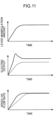
- the upper graph in Fig. 5 exemplifies a relationship between a time and a manipulation amount (lever manipulation amount) of a boom manipulation received by the boom manipulation device 43.
- the middle graph in Fig. 5 exemplifies a relationship between a time and an electric output which is output from the subtractor 7 when the boom manipulation device 43 receives the boom manipulation (boom raising manipulation or boom lowering manipulation) as shown in the upper graph.
- the electric output which is output from the subtractor 7 represents an actual input u p (k) serving as a control instruction input from the subtractor 7 to the pump proportional valve 46 or the boom proportional valve 44 in the controlled object 100.
- the middle graph shows an effect of compensating a fluctuation in static characteristics and compensating a fluctuation in dynamic characteristics by the static compensator 5, the dynamic compensator 6, and the subtractor 7.
- the solid line denotes an example of a relationship between a time and an electric output in no performance of the compensation for the fluctuation in the static characteristics and of the compensation for the fluctuation in the dynamic characteristics.
- the dashed line denotes an example of a relationship between a time and an electric output in performance of the compensation for the fluctuation in the static characteristics and of the compensation for the fluctuation in the dynamic characteristics in the hydraulic excavator 20 according to the embodiment.
- a rise of the electric output (the actual input u p (k)) is modified through the compensation for the fluctuation in the dynamic characteristics.
- overshooting of the rise is suppressed and a desirable rise slope is obtainable as denoted by the dashed line.
- the performance of the compensation for the fluctuation in the static characteristics leads to modification of steady-state characteristics of the electric output (actual input u p (k)). In this manner, a desired steady-state value is obtained as denoted by the dashed line.
- the lower graph in Fig. 5 exemplifies a relationship between a time and a control output which the boom cylinder 27 in the controlled object 100 outputs.
- the control output of the boom cylinder 27 may include an operation speed of the boom cylinder 27 or a physical quantity corresponding to the operation speed of the boom cylinder 27 as described above.
- the physical quantity may be a flow rate of the hydraulic fluid being supplied to the boom cylinder 27, a flow rate of the hydraulic fluid being discharged from the boom cylinder 27, or another physical quantity.
- the lower graph shows an effect of adjustment of each of the static parameter and the dynamic parameter by the parameter adjuster 9.
- the solid line denotes an example of a relationship between a time and a control output in no performance of the adjustment of the static parameter and the dynamic parameter by the parameter adjuster 9.
- the dashed line denotes an example of a relationship between a time and a control output in performance of the adjustment of the static parameter and the dynamic parameter by the parameter adjuster 9 in the hydraulic excavator 20 according to the embodiment.
- the parameter adjuster 9 adjusts each of the static parameter and the dynamic parameter in the hydraulic excavator 20 according to the embodiment.
- the input and output characteristics of the control input u c (k) and the control output y(k) are maintained to ideal input and output characteristics at the time of designing the controller 4.
- the controlled object 100 is appropriately controllable by using the controller 4 in the initial design.
- Fig. 6 is a block diagram showing a feedback system constituting the control loop 50.
- the feedback system is expressed by the following formula.
- Formula 1 u p k f 0 k u c k ⁇ K P k y k ⁇ K D k ⁇ y k
- the signs "u p (k)”, “y(k)”, “u c (k)”, and “P” respectively denote an actual input, a control output, a control input, and a controlled object.
- the signs "f 0 (k)”, “K p (k)”, “K D (k)” respectively denote parameters.
- the parameter adjuster 9 tunes the parameters f 0 (k), K p (k), K D (k) online by using the iterative least square technique.
- the iterative least square technique has a merit of a low calculation cost.
- the parameter adjuster 9 calculates a parameter of each of the static compensator 5 and the dynamic compensator 6 from operational data (including the actual input u p (k) and the control output y(k)).
- Equation (1) is changed as follows.
- Equation (3) parameters " ⁇ 1 (k)”, “ ⁇ 2 (k)”, “ ⁇ 3 (k)” are expressed by Equation (4).
- a response obtainable in inputting of the control input u c (k) to the input and output model G m (z -1 ) indicating an ideal transfer function of the control loop 50 is defined as an ideal output y r (k, ⁇ (k)).
- the ideal output y r (k, ⁇ (k)) is expressed by Equation (5).
- An evaluation function J is defined as follows.
- the sign "N” denotes the number of data
- the parameter ⁇ (k) is adjusted in such a manner that the control output y(k) follows the ideal output y r (k) by minimizing the evaluation function J.
- Use of the optimized parameter allows input and output characteristics of the control loop 50 including the static compensator 5, the dynamic compensator 6, and the controlled object 100 to agree with input and output characteristics of the input and output model G m (z -1 ).
- An initial value ⁇ (0) of an error covariance matrix ⁇ (k) and an initial value 8(0) of an estimative value ⁇ (k) are defined by the following formula.
- the sign " ⁇ ” is a certain real number satisfying " ⁇ > 0".
- the sign "I” denotes an identity matrix of 3 ⁇ 3.
- the sign " ⁇ i (0)” denotes a certain real number.
- the real number ⁇ i (0) is defined as not “0” under the condition that the gain f 0 is not "0".
- Fig. 3 shows each of the pump control device 14 and the valve control device 13.
- the control loop 50 represents a downstream control loop formed of a control system including the static compensator 5 and the dynamic compensator 6 in combination.
- the controller 4 represents an upstream control loop.
- the controller 4 is formed of a PID (proportional-integral-derivative) control system having a fixed control parameter.
- the parameter of each of the static compensator 5 and the dynamic compensator 6 is adjusted so that the input and output characteristics of the control loop 50 agree with the input and output characteristics of the input and output model G m (z -1 ).
- the downstream control loop 50 has input and output characteristics equivalent to those of the input and output model G m (z -1 ).
- the upstream controller 4 can be designed on the basis of the ideal input and output model G m (z -1 ).
- the controller 4 in the embodiment is formed of a PID control system expressed by Equation (17).
- the ideal input and output model G m (z -1 ) of the control loop 50 is designed as follows.
- G m z ⁇ 1 z ⁇ 1 P 1 P z ⁇ 1
- the denominator "P(z -1 )" is expressed by the following formula.
- the coefficients "pi”, "p 2 " are expressed by the following formula.
- the sign "T s " denotes a sampling time
- the signs " ⁇ ", “ ⁇ ” respectively denote dynamic parameters, such as rise characteristics and damping characteristics, of the controlled object 100.
- a designer appropriately sets the dynamic parameters on the basis of the input and output characteristics of the controlled object 100.
- Fig. 7 is a diagram showing another example of a hydraulic circuit and a control unit 1 included in the hydraulic excavator 20.
- the hydraulic excavator 20 further includes a mode input receiver 61.
- the mode input receiver 61 receives an input to change a control mode in the hydraulic excavator 20 between a first mode and a second mode which are preset.
- the input is made by a work-related person, such as an operator, a work manager, and other related person.
- the mode input receiver 61 may include, for example, a switch provided inside the cabin 31.
- the first mode is a mode in which the parameter adjuster 9 adjusts a parameter
- the second mode is a mode in which the parameter adjuster 9 withholds the adjustment of the parameter.
- compensation for a fluctuation in static characteristics and compensation for a fluctuation in dynamic characteristics may be performed, or the compensation for each fluctuation may be withheld.
- the parameter adjuster 9 in each of the pump control device 14 and the valve control device 13 withholds a control of adjusting a static parameter and a dynamic parameter when the control mode is in the second mode.
- the parameter adjuster 9 in each of the pump control device 14 and the valve control device 13 executes the control of adjusting the static parameter and the dynamic parameter when the control mode is changed from the second mode to the first mode in response to an input received by the mode input receiver 61 from the work-related person.
- This modification achieves a control reflecting a will of an operator. Specifically, for instance, a skilled operator can maneuver a hydraulic working machine by effectively using the skill thereof without relying on an automatic control by the hydraulic working machine, and an unskilled operator having fewer experiences can improve work efficiency by relying on the automatic control by the hydraulic working machine.
- Fig. 8 is a diagram showing still another example of a hydraulic circuit and a control unit 1 included in the hydraulic excavator 20.
- the control unit 1 further includes a determinator 16.
- the determinator 16 may include a replacement determinator that determines replacement of at least one component of the working device 23 with another component.
- the determinator 16 may include a deterioration determinator that determines a deterioration of the hydraulic excavator 20.
- the replacement determinator determines, on the basis of a predetermined determination criterion, whether one component of the working device 23 has been replaced with another component.
- the deterioration determinator determines, on the basis of a predetermined determination criterion, a deterioration of the hydraulic excavator 20.
- detailed example cases of replacement of at least one component of the working device 23 with another component include a case where a leading end attachment of the working device 23 is replaced with another leading end attachment having a different weight of the same kind, and a case where the leading end attachment of the working device 23 is replaced with another leading end attachment of a different kind.
- Examples of the kind of leading end attachment include a grapple, a crusher (demolisher), a breaker, a fork, and other leading end attachments in addition to the bucket 26.
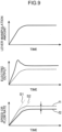
- the upper graph in Fig. 9 exemplifies a relationship between a time and a manipulation amount (lever manipulation amount) of a boom manipulation received by the boom manipulation device 43.
- the middle graph in Fig. 9 exemplifies a relationship between a time and an electric output which is output from the subtractor 7 when the boom manipulation device 43 receives the boom manipulation (boom raising manipulation or boom lowering manipulation) as shown in the upper graph.
- the upper graph and the middle graph in Fig. 9 are the same as the upper graph and the middle graph in Fig. 5 , and thus description therefor is omitted.
- the lower graph in Fig. 9 exemplifies a relationship between a time and a control output which the boom cylinder 27 in the controlled object 100 outputs.
- the solid line denotes an example of a relationship between a time and a control output in no performance of the adjustment of the static parameter and the dynamic parameter by the parameter adjuster 9.
- the dashed line denotes an example of a relationship between a time and a control output in performance of the adjustment of the static parameter and the dynamic parameter by the parameter adjuster 9 in the hydraulic excavator 20 according to the embodiment.
- a slope s2 of a rise of the control output denoted by the solid line in the lower graph in Fig. 9 and a steady-state value f2 of the control output largely fluctuate respectively from a slope s1 of a rise of an ideal control output and a steady-state value f1 of the ideal control output at the time of designating the controller 4.
- the determination criterion may include, for example, a criterion that the slope s2 of the rise of the control output deviates from the slope s1 of the rise of the ideal control output by a preset threshold "se" or larger.
- the determination criterion may include, for example, a criterion that the steady-state value f2 of the control output deviates from the steady-state value f1 of the ideal control output by a preset threshold "fe” or larger.
- the determinator 16 can calculate, on the basis of the control output input from the output detector 12 to the control unit 1, the slope of the rise of the control output and the steady-state value of the control output.
- the parameter adjuster 9 of the pump control device 14 withholds the control of adjusting a static parameter and a dynamic parameter, when the determinator 16 (the replacement determinator) determines that at least one component of the working device 23 has not been replaced with another component, or when the determinator 16 (the deterioration determinator) determines that the hydraulic excavator 20 has not deteriorated.
- the parameter adjuster 9 of the pump control device 14 executes the control of adjusting the static parameter and the dynamic parameter, when the determinator 16 (the replacement determinator) determines that the at least one component of the working device 23 has been replaced with another component, or when the determinator 16 (deterioration determinator) determines that the hydraulic excavator 20 has deteriorated.
- the parameter adjuster 9 of the valve control device 13 withholds the control of adjusting a static parameter and a dynamic parameter, when the determinator 16 (the replacement determinator) determines that at least one component of the working device 23 has not been replaced with another component, or when the determinator 16 (deterioration determinator) determines that the hydraulic excavator 20 has not deteriorated.
- the parameter adjuster 9 of the valve control device 13 executes the control of adjusting the static parameter and the dynamic parameter, when the determinator 16 (the replacement determinator) determines that the at least one component of the working device 23 has been replaced with another component, or when the determinator 16 (deterioration determinator) determines that the hydraulic excavator 20 has deteriorated.
- the parameter adjuster 9 adjusts a static parameter and a dynamic parameter. In this manner, even when the input and output characteristics of the controlled object 100 largely fluctuate due to replacement of a component or due to a deterioration of the hydraulic excavator 20, the input and output characteristics of the control input u c (k) and the control output y(k) are maintained to ideal input and output characteristics at the time of designing the controller 4. Hence, even when the input and output characteristics of the controlled object 100 largely fluctuate, the controlled object 100 is appropriately controllable by using the controller 4 in the initial design.
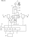
- Fig. 10 is a diagram showing still another example of a hydraulic circuit and a control unit 1 included in the hydraulic excavator 20.
- the hydraulic excavator 20 further includes a characteristics input receiver 62.
- the characteristics input receiver 62 receives an input to change a setting of input and output characteristics of a control input u c (k) and a control output y(k).
- a slope of a rise of a control output is changeable to a slope preferable to an operator.
- a work-related person, such as the operator gives an input to change input characteristics, e.g., a desired slope of a rise, to the characteristics input receiver 62.
- the characteristics input receiver 62 outputs, to the control unit 1, a signal corresponding to the input.
- the control unit 1 changes, on the basis of the signal corresponding to the input, the setting of the input and output characteristics of the control input u c (k) and the control output y(k). Specifically, the control unit 1 changes, for example, the setting of the input and output model G m (z -1 ) in response to an input by the work-related person. In this manner, response characteristics (input and output characteristics), such as the slope of the rise of the control output, are changed to have a slope preferable to the operator.
- a controlled object 100 to be controlled by a pump control device may include a pump proportional valve, a pump, and an arm cylinder
- a controlled object 100 to be controlled by a valve control device may include an arm proportional valve, an arm control valve, and the arm cylinder.
- the controlled object 100 to be controlled by the pump control device may include a pump proportional valve, a pump, and a bucket cylinder
- the controlled object 100 to be controlled by the valve control device may include a bucket proportional valve, a bucket control valve, and the bucket cylinder.
- the controlled object 100 to be controlled by the pump control device may include a pump proportional valve, a pump, and a slewing motor
- the controlled object 100 to be controlled by the valve control device may include a slewing proportional valve, a slewing control valve, and the slewing motor.
- each of the instruction calculator of the pump control device 14 and the instruction calculator of the valve control device 13 has the target setter 2, the subtractor 3, the controller 4, the static compensator 5, the dynamic compensator 6, and the subtractor 7.
- an instruction calculator of a pump control device is configured to calculate a control instruction of causing a controlled object including a hydraulic pump and an actuator to operate by using a manipulation amount of a manipulation and at least one pump control parameter, and to input the control instruction to the controlled object, therefore, the instruction calculator of a pump control device is not limited to the configuration of the embodiment.
- an instruction calculator of a valve control device is configured to calculate a control instruction of causing a controlled object including a control valve and an actuator to operate by using the manipulation amount of the manipulation and at least one valve control parameter, and to input the control instruction to the controlled object, therefore, the instruction calculator of a valve control device is not limited to the configuration of the embodiment.
- the parameter adjuster 9 may adjust a static gain f 0 and a dynamic gain (K p , K D ) by using a database-driven control way.
- the database-driven control way includes calculating a parameter suitable for a current state of a controlled object on the basis of a parameter having been calculated in past and stored in a database.
- each of the control devices 13, 14 further includes a database that stores a static gain f 0 and a dynamic gain (K p , K D ) having been calculated in past.
- the parameter adjuster 9 acquires, from the memory 11, a request point indicating the current state of the controlled object 100.
- the request point includes, for example, control outputs y(k) and ideal outputs y r (k) in a period from a certain sample to a couple of previous samples.
- the parameter adjuster 9 calculates a distance between the request point and each of parameter sets stored in the database, and extracts k-parameter sets in short distance order.
- the parameter set includes, for example, a set of a static gain f 0 , a proportional gain K p , and a derivative gain K D .
- the parameter adjuster 9 obtains a weight coefficient for each of the extracted k-parameter sets such that a value of the weight coefficient is larger as the distance is shorter.
- the parameter adjuster 9 averages the k-parameter sets by using the obtained weight coefficient, calculates a final parameter set, and defines the final parameter set as the static gain f 0 and the dynamic gain (K p , K D ).
- An arithmetic expression for use in calculating a dynamic compensatory input by the dynamic compensator 6 may include a product of a quadratic derivative term of the control output y(k) and a quadratic derivative gain.
- the hydraulic working machine may be a working machine of a hybrid type using an engine and an electric motor in combination.
- the working machine of the hybrid type includes, for example, a generator motor and an electric power storage device.
- the generator motor charges power based on electricity generated with a drive force of an engine to the electric power storage device, and causes the working machine to execute a power running operation by using the power stored in the electric power storage device to assist the engine.
- the present invention provides a hydraulic working machine that allows each of a power running operation and a non-power running operation to approximate to an ideal operation suited to a manipulation amount even in a case of a large fluctuation in input and output characteristics of a controlled object.
- a hydraulic working machine includes: a support body; a movable part that is shiftable relative to the support body; a hydraulic pump that discharges hydraulic fluid; an actuator that receives a supply of the hydraulic fluid to cause the movable part to operate; a control valve that is located between the hydraulic pump and the actuator, and opens and closes to change a flow rate of the hydraulic fluid to be supplied to the actuator; a manipulation device that receives a manipulation for an operation of the movable part; an operation determinator that determines whether the operation of the movable part performed in response to the manipulation received by the manipulation device is a power running operation of the movable part to operate against a load acting on the movable part or a non-power running operation of the movable part to operate in a direction of the load acting on the movable part; a pump control device that regulates a discharge rate of the hydraulic pump; a valve control device that regulates an opening degree of the control valve; and an output detector that detects a control output being an output
- the pump control device has: a pump instruction calculator that calculates, by using a manipulation amount of the manipulation and at least one pump control parameter, a control instruction of causing a controlled object including the hydraulic pump and the actuator to operate, and inputs the calculated control instruction to the controlled object; a pump control ideal output calculator that calculates an ideal output of the actuator, the ideal output being associated with the manipulation amount of the manipulation; and a pump control parameter adjuster that adjusts the at least one pump control parameter to reduce a difference between the control output and the ideal output when the operation of the movable part is the power running operation.
- the valve control device has: a valve instruction calculator that calculates, by using the manipulation amount of the manipulation and at least one valve control parameter, a control instruction of causing a controlled object including the control valve and the actuator to operate, and inputs the calculated control instruction to the controlled object; a valve control ideal output calculator that calculates an ideal output of the actuator, the ideal output being associated with the manipulation amount of the manipulation; and a valve control parameter adjuster that adjusts the at least one valve control parameter to reduce a difference between the control output and the ideal output when the operation of the movable part is the non-power running operation.
- a pump control parameter for calculating a control instruction to a controlled object in a power running operation is adjusted to reduce a difference between a control output and an ideal output
- a valve control parameter for calculating a control instruction to a controlled object in a non-power running operation is adjusted to reduce a difference between a control output and an ideal output.
- the movable part includes a boom tiltably supported on the support body
- the power running operation includes a boom rising operation being an operation of the boom that a distal end of the boom rises away from ground
- the non-power running operation includes a boom lowering operation being an operation of the boom that the distal end of the boom approaches the ground
- the operation determinator determines that the operation of the movable part is the power running operation when the manipulation device receives a boom raising manipulation being a manipulation for causing the boom to perform the boom rising operation
- determines that the operation of the movable part is the non-power running operation when the manipulation device receives a boom lowering manipulation being a manipulation for causing the boom to perform the boom lowering operation.
- This configuration achieves, by adjusting each of the pump control parameter and the valve control parameter, more appropriate adjustment of the drive force for the boom rising operation against the own weight of the working device including the boom and a more appropriate regulation of the flow rate of the hydraulic fluid for the boom lowering operation in a direction of the own weight of the working device including the boom .
- control output of the actuator includes an operation speed of the actuator or a physical quantity corresponding to the operation speed
- output detector includes a sensor for detecting the operation speed or the physical quantity. This configuration enables the output detector of the hydraulic working machine to detect, as a reference control output for adjusting a parameter, the operation speed of the actuator or a physical quantity corresponding to the operation speed.
- the hydraulic working machine may further include a mode input receiver that receives an input to change a control mode in the hydraulic working machine between a first mode and a second mode which are preset.
- the pump control parameter adjuster may execute a control of adjusting the at least one pump control parameter when the control mode is in the first mode, and withhold the control of adjusting the at least one pump control parameter when the control mode is in the second mode.
- the valve control parameter adjuster may execute a control of adjusting the at least one valve control parameter when the control mode is in the first mode, and withhold the control of adjusting the at least one valve control parameter when the control mode is in the second mode.
- a work-related person such as an operator or a work manager, can cause the pump control device and the valve control device to execute the control of adjusting a corresponding parameter at an appropriate time when the work-related person determines necessity of the adjustment.
- This configuration achieves a control reflecting a will of the operator.
- the hydraulic working machine preferably further includes: a working device including the movable part; and a replacement determinator that determines whether at least one component of the working device has been replaced with another component.
- the pump control parameter adjuster preferably executes the control of adjusting the at least one pump control parameter when the replacement determinator determines that the at least one component of the working device has been replaced with the another component.
- the valve control parameter adjuster preferably executes the control of adjusting the at least one valve control parameter when the replacement determinator determines that the at least one component of the working device has been replaced with the another component. In this configuration, when the replacement determinator determines that a part of the components or all the components of the working device has been replaced, each of the pump control device and the valve control device adjusts the corresponding control parameter. This configuration enables an automatic control of adjusting the control parameter in high demand for the adjustment of the control parameter while suppressing a load of a computation control.
- the hydraulic working machine preferably further includes a deterioration determinator that determines, on the basis of a predetermined determination criterion, a deterioration of the hydraulic working machine. It is further preferable that the pump control parameter adjuster executes the control of adjusting the at least one pump control parameter when the deterioration determinator determines that the hydraulic working machine has deteriorated, and the valve control parameter adjuster executes the control of adjusting the at least one valve control parameter when the deterioration determinator determines that the hydraulic working machine has deteriorated. In this configuration, when the deterioration determinator determines that the hydraulic working machine has deteriorated, each of the pump control device and the valve control device adjusts the corresponding control parameter. This configuration enables an automatic control of adjusting the control parameter in high demand for the adjustment of the control parameter while suppressing a load of a computation control.
- the pump instruction calculator may calculate a control instruction of causing a controlled object including the hydraulic pump and the actuator to operate by using a manipulation amount of the manipulation and at least one pump control parameter.
- a specific configuration is not particularly limited, but it is preferable to include, for example, the configuration described below.
- the pump instruction calculator further has: a target setter that sets a target output in accordance with the manipulation amount of the manipulation, the target output serving as a target of the control output; and a control input calculator that calculates a control input to eliminate an error between the target output and the control output, and the pump control device further has a control input compensator that calculates the control instruction by modifying the control input so as to compensate a fluctuation in characteristics of the controlled object on the basis of at least one of the control input and the control output, and on the basis of the at least one pump control parameter, and inputs the calculated control instruction to the controlled object.
- This configuration allows a power running operation to more accurately approximate to an ideal operation suited to a manipulation amount even in a case of a large fluctuation in input and output characteristics of the controlled object.
- the at least one pump control parameter includes a static parameter and a dynamic parameter
- the control input compensator of the pump control device includes: a static compensator that calculates, on the basis of the static parameter and the control input, a static compensatory input of compensating a fluctuation in static characteristics of the controlled object; a dynamic compensator that calculates, on the basis of the dynamic parameter and the control output, a dynamic compensatory input of compensating a fluctuation in dynamic characteristics of the controlled object; and a synthesizer that calculates the control instruction by synthesizing the static compensatory input and the dynamic compensatory input, and inputs the calculated control instruction to the controlled object.
- control input is modified by the dynamic compensatory input calculated on the basis of the dynamic parameter and the control output, and thus, a fluctuation in the dynamic characteristics of the controlled object, such as rise characteristics and damping characteristics, can be compensated.
- control input is modified by the static compensatory input calculated on the basis of the control input and the static parameter, and thus, a fluctuation in the static characteristics of the controlled object, such as a fluctuation in a scale of the control input accompanied by synthetization with the dynamic compensatory input, can be compensated.
- the pump control ideal output calculator preferably calculates the ideal output corresponding to the control input by using an input and output model defining an ideal input and output relationship between the control input and the control output.
- This configuration adjusts the static parameter and the dynamic parameter by using the ideal output and the control output each calculated during the operation of the controlled object.
- the valve instruction calculator is configured to calculate a control instruction of causing a controlled object including the control valve and the actuator to operate by using the manipulation amount of the manipulation and at least one valve control parameter, therefore, a specific configuration is not particularly limited, but it is preferable to include, for example, a configuration described below.
- the valve instruction calculator preferably further has: a target setter that sets a target output in accordance with the manipulation amount of the manipulation, the target output serving as a target of the control output; and a control input calculator that calculates a control input to eliminate an error between the target output and the control output.
- the valve control device preferably further has a control input compensator that calculates the control instruction by modifying the control input so as to compensate a fluctuation in characteristics of the controlled object on the basis of at least one of the control input and the control output, and on the basis of the at least one valve control parameter, and inputs the calculated control instruction to the controlled object.
- This configuration allows a non-power running operation to more accurately approximate to an ideal operation suited to a manipulation amount even in a case of a large fluctuation in input and output characteristics of the controlled object.
- the at least one valve control parameter includes a static parameter and a dynamic parameter
- the control input compensator of the valve control device further includes: a static compensator that calculates, on the basis of the static parameter and the control input, a static compensatory input of compensating a fluctuation in static characteristics of the controlled object; a dynamic compensator that calculates, on the basis of the dynamic parameter and the control output, a dynamic compensatory input of compensating a fluctuation in dynamic characteristics of the controlled object; and a synthesizer that calculates the control instruction by synthesizing the static compensatory input and the dynamic compensatory input, and inputs the calculated control instruction to the controlled object.
- control input is modified by the dynamic compensatory input calculated on the basis of the dynamic parameter and the control output, and thus, a fluctuation in the dynamic characteristics of the controlled object, such as rise characteristics and damping characteristics, can be compensated.
- control input is modified by the static compensatory input calculated on the basis of the control input and the static parameter, and thus, a fluctuation in the static characteristics of the controlled object, such as a fluctuation in a scale of the control input accompanied by synthetization with the dynamic compensatory input, can be compensated.
- the valve control ideal output calculator preferably calculates the ideal output corresponding to the control input by using an input and output model defining an ideal input and output relationship between the control input and the control output.
- This configuration adjusts the static parameter and the dynamic parameter by using the ideal output and the control output each calculated during the operation of the controlled object.
- the hydraulic working machine preferably further includes a characteristics input receiver that receives an input to change a setting of input and output characteristics of the control input and the control output.
- a characteristics input receiver that receives an input to change a setting of input and output characteristics of the control input and the control output.
Landscapes
- Engineering & Computer Science (AREA)
- General Engineering & Computer Science (AREA)
- Mining & Mineral Resources (AREA)
- Civil Engineering (AREA)
- Structural Engineering (AREA)
- Physics & Mathematics (AREA)
- Fluid Mechanics (AREA)
- Chemical & Material Sciences (AREA)
- Analytical Chemistry (AREA)
- Mechanical Engineering (AREA)
- Operation Control Of Excavators (AREA)
- Fluid-Pressure Circuits (AREA)
Abstract
Description
- The present invention relates to a hydraulic working machine including a control device that controls a controlled object.
- An improvement in the operability of a manipulation by an operator in a hydraulic working machine, such as a hydraulic excavator, leads to an improvement in a work efficiency on a worksite.
- For instance,
Patent Literature 1 discloses a hydraulic actuator control device including an electric current controller. The hydraulic actuator control device supplies, to a solenoid proportional flow rate control valve, an electric current larger than a target electric current corresponding to a manipulation amount of a manipulation lever for only a predetermined short time period at a start of a driving manipulation from a neutral position with an aim of improving the operability by reducing response delay in activating the hydraulic actuator from a suspension state. -
Patent Literature 2 discloses a construction machine including a controller that outputs a command current for driving a solenoid proportional valve in response to a manipulation signal from a manipulation device. The controller has a correction function to correct the command current in such a manner that the command current is higher than a target current corresponding to a manipulation amount of a manipulation device for a preset predetermined time at a time of starting to manipulate the manipulation device from a neutral position thereof with an aim of ensuring an initial response that varies in accordance with a type of hydraulic actuator. -
Patent Literature 3 discloses a hydraulic working machine including a control device to improve initial responsiveness of a hydraulic actuator while ensuring energy saving performance. The control device modifies a pump target flow rate by adding a predetermined modification flow rate, which is larger than a pump minimum flow rate of a first hydraulic pump, to a pump target flow rate for a period to a lapse of a predetermined modification time after a manipulation of a first manipulation lever from a neutral position thereof. -
Patent Literature 4 discloses a construction machine including a controller for keeping a specific relationship regardless of a change in a reach, the specific relationship being a relationship between a boom manipulation amount and a rising or lowering amount of an attachment leading end in a rising or lowering operation of the attachment leading end to rise or to be lowered. In a boom raising manipulation in a loading direction, the controller modifies, in accordance with the reach, a pump flow rate determined by a boom raising manipulation amount, specifically, the controller decreases the pump flow rate when the reach is long and increases the pump flow rate when the reach is short. By contrast, in the boom lowering operation in which the own weight of the attachment acts, a secondary pressure of a proportional valve provided on a boom lowering pilot line is modified in accordance with the reach to thereby reduce an opening degree of a control valve when the reach is long and increase the opening degree when the reach is short. - Meanwhile, input and output characteristics of a controlled object including: a proportional valve that receives an input of an instruction from a control device; and an actuator that causes a movable part, such as a boom, to operate may largely fluctuate due to, for example, replacement of a leading end attachment, an aging deterioration of a component of a working machine, or other factor. In this regard, the controller or control device disclosed in each of
Patent Literatures 1 to 4 does not consider such a fluctuation in the input and output characteristics of the controlled object. A control output being an output of the actuator thus fails to be suited to a manipulation amount in a case of a large fluctuation in the input and output characteristics of the controlled object. Further, a controlled object to be targeted in a power running operation like a boom rising operation differs from a controlled object to be targeted in a non-power running operation like a boom lowering operation. A rate of the aging deterioration varies depending on each component constituting the corresponding controlled object. Under the circumstances, each of the power running operation and the non-power running operation of the movable part is required to approximate to an ideal operation suited to the manipulation amount even in a case of a large fluctuation in the input and output characteristics of the controlled object. -
- Patent Literature 1:
Japanese Unexamined Patent Publication No HEI 5-195546 - Patent Literature 2:
Japanese Unexamined Patent Publication No. 2017-110774 - Patent Literature 3:
Japanese Unexamined Patent Publication No. 2019-44933 - Patent Literature 4:
Japanese Unexamined Patent Publication No. 2012-225084 - The present invention has been achieved to solve the aforementioned drawbacks with an aim of providing a hydraulic working machine that allows each of a power running operation and a non-power running operation to approximate to an ideal operation suited to a manipulation amount even in a case of a large fluctuation in input and output characteristics of a controlled object.
- A hydraulic working machine according to one aspect of the present invention includes: a support body; a movable part that is shiftable relative to the support body; a hydraulic pump that discharges hydraulic fluid; an actuator that receives a supply of the hydraulic fluid to cause the movable part to operate; a control valve that is located between the hydraulic pump and the actuator, and opens and closes to change a flow rate of the hydraulic fluid to be supplied to the actuator; a manipulation device that receives a manipulation for an operation of the movable part; an operation determinator that determines whether the operation of the movable part performed in response to the manipulation received by the manipulation device is a power running operation of the movable part to operate against a load acting on the movable part or a non-power running operation of the movable part to operate in a direction of the load acting on the movable part; a pump control device that regulates a discharge rate of the hydraulic pump; a valve control device that regulates an opening degree of the control valve; and an output detector that detects a control output being an output of the actuator. The pump control device has: a pump instruction calculator that calculates, by using a manipulation amount of the manipulation and at least one pump control parameter, a control instruction of causing a controlled object including the hydraulic pump and the actuator to operate, and inputs the calculated control instruction to the controlled object; a pump control ideal output calculator that calculates an ideal output of the actuator, the ideal output being associated with the manipulation amount of the manipulation; and a pump control parameter adjuster that adjusts the at least one pump control parameter to reduce a difference between the control output and the ideal output when the operation of the movable part is the power running operation. The valve control device has: a valve instruction calculator that calculates, by using the manipulation amount of the manipulation and at least one valve control parameter, a control instruction of causing a controlled object including the control valve and the actuator to operate, and inputs the calculated control instruction to the controlled object; a valve control ideal output calculator that calculates an ideal output of the actuator, the ideal output being associated with the manipulation amount of the manipulation; and a valve control parameter adjuster that adjusts the at least one valve control parameter to reduce a difference between the control output and the ideal output when the operation of the movable part is the non-power running operation.
-
-
Fig. 1 is a side view of an example of a hydraulic working machine according to an embodiment of the present invention. -
Fig. 2 is a diagram showing an example of a hydraulic circuit and a control unit included in the hydraulic working machine. -
Fig. 3 is a block diagram showing an example of a control device included in the control unit. -
Fig. 4 is a flowchart showing an example of a process by the control device. -
Fig. 5 includes graphs respectively showing an example of a relationship between a time and a manipulation amount of a manipulation received by a manipulation device included in the hydraulic working machine, an example of a relationship between a time and an electric output, and an example of a relationship between a time and a control output. -
Fig. 6 is a block diagram showing a feedback system constituting a control loop. -
Fig. 7 is a diagram showing another example of a hydraulic circuit and a control unit in the hydraulic working machine. -
Fig. 8 is a diagram showing still another example of a hydraulic circuit and a control unit in the hydraulic working machine. -
Fig. 9 includes graphs respectively showing another example of a relationship between a time and a manipulation amount of a manipulation received by a manipulation device included in the hydraulic working machine, another example of a relationship between a time and an electric output, and another example of a relationship between a time and a control output. -
Fig. 10 is a diagram showing still another example of a hydraulic circuit and a control unit in the hydraulic working machine. -
Fig. 11 includes graphs respectively showing still another example of a relationship between a time and a manipulation amount of a manipulation received by a manipulation device included in the hydraulic working machine, still another example of a relationship between a time and an electric output, and still another example of a relationship between a time and a control output. - Hereinafter, an embodiment of the present invention will be described with reference to the accompanying drawings.
Fig. 1 is a side view of ahydraulic excavator 20 which is an example of a hydraulic working machine according to an embodiment.Fig. 2 is a diagram showing an example of a hydraulic circuit and a control unit included in thehydraulic excavator 20. - As shown in
Fig. 1 andFig. 2 , thehydraulic excavator 20 includes: a lowertraveling body 21 of a self-running type; anupper slewing body 22 slewably supported on the lower travelingbody 21; aworking device 23; a plurality of hydraulic actuators; a plurality of hydraulic pumps; apilot pump 47; a plurality of control valves; a plurality of manipulation devices; a plurality of proportional valves; an output detector 12 (seeFig. 3 ); and acontrol unit 1. - The
upper slewing body 22 includes anupper frame 30 slewably supported on thelower traveling body 21, acabin 31 supported on theupper frame 30, and acounterweight 32 disposed in the rear of thecabin 31. The lowertraveling body 21 and theupper slewing body 22 serve as an example of a support body. - The
working device 23 includes aboom 24 tiltably supported on theupper frame 30, anarm 25 rotatably supported on a distal end of theboom 24, and abucket 26 rotatably supported on a distal end of thearm 25. Theboom 24 serves as an example of the movable part. - The hydraulic actuators include a
boom cylinder 27, anarm cylinder 28, abucket cylinder 29, and aslewing motor 33. - Each of the hydraulic pumps is a hydraulic pump for supplying hydraulic fluid to at least one of the hydraulic actuators. The hydraulic pumps include a
hydraulic pump 41 of a variable displacement type shown inFig. 2 . Thepilot pump 47 is a hydraulic pump for supplying a pilot pressure to each of the control valves. Each of the hydraulic pumps and thepilot pump 47 is driven by an unillustrated engine. -
Fig. 2 representatively shows a circuit of causing theboom cylinder 27 to operate without illustrations of circuits of respectively causing thearm cylinder 28, thebucket cylinder 29, and theslewing motor 33 to operate. Each of the circuits of respectively causing thearm cylinder 28, thebucket cylinder 29, and theslewing motor 33 to operate has the same structure as the circuit of causing theboom cylinder 27 shown inFig. 2 to operate. - The
boom cylinder 27 is a hydraulic cylinder that receives a supply of the hydraulic fluid from thehydraulic pump 41 shown inFig. 2 to cause theboom 24 to perform a rising or lowering operation. As illustrated inFig. 1 , theboom cylinder 27 includes a cylinder tube having a proximal end rotatably attached to theupper frame 30 of theupper slewing body 22, and theboom cylinder 27 includes a piston rod having a distal end rotatably attached to theboom 24. As shown inFig. 2 , theboom cylinder 27 has arod chamber 27R and ahead chamber 27H. - The
arm cylinder 28 is a hydraulic cylinder that receives a supply of the hydraulic fluid from any one of the hydraulic pumps to cause thearm 25 to rotate. Thebucket cylinder 29 is a hydraulic cylinder that receives a supply of the hydraulic fluid from any one of the hydraulic pumps to cause thebucket 26 to rotate. Theslewing motor 33 is a hydraulic motor that receives a supply of the hydraulic fluid from any one of the hydraulic pumps to cause theupper frame 30 of theupper slewing body 22 to slew to thelower traveling body 21. - The control valves include a
boom control valve 42 shown inFig. 2 , an unillustrated arm control valve, an unillustrated bucket control valve, and an unillustrated slewing control valve. Each of the control valves has a spool and a pair of pilot ports for receiving the pilot pressure from thepilot pump 47. - The
boom control valve 42 is located between thehydraulic pump 41 and theboom cylinder 27, and opens and closes to change a direction and a flow rate of the hydraulic fluid to be supplied to theboom cylinder 27. The arm control valve is located between any one of the hydraulic pumps and thearm cylinder 28, and opens and closes to change a direction and a flow rate of the hydraulic fluid to be supplied to thearm cylinder 28. The bucket control valve is located between any one of the hydraulic pumps and thebucket cylinder 29, and opens and closes to change a direction and a flow rate of the hydraulic fluid to be supplied to thebucket cylinder 29. The slewing control valve is located between any one of the hydraulic pumps and the slewingmotor 33, and opens and closes to change a direction and a flow rate of the hydraulic fluid to be supplied to the slewingmotor 33. - The manipulation devices include a boom manipulation device 43 (see
Fig 2 ) that receives a manipulation for an operation of theboom 24, an unillustrated arm manipulation device that receives a manipulation for an operation of thearm 25, an unillustrated bucket manipulation device that receives a manipulation for an operation of thebucket 26, and an unillustrated slewing manipulation device for a slewing operation of theupper slewing body 22 to the lower travelingbody 21. Each of the manipulation devices has a manipulation lever for allowing an operator to give a manipulation thereto. Each of the manipulation devices represents an electric lever device that outputs an instruction signal (electric signal) corresponding to a manipulation received by the manipulation lever and a manipulation amount thereof. The output instruction signal is input to thecontrol unit 1. - Specifically, the
boom manipulation device 43 is configured to receive a boom raising manipulation for causing theboom 24 to perform a boom rising operation and a boom lowering manipulation for causing theboom 24 to perform a boom lowering operation. The boom rising operation is an operation of theboom 24 that the distal end of theboom 24 rises away from the ground, and the boom lowering operation is an operation of theboom 24 that the distal end of theboom 24 approaches the ground. The boom rising operation requires a regulation of a discharge rate of thehydraulic pump 41 to shift the workingdevice 23 in a direction opposite to a direction of the gravity as shown inFig. 2 . The boom rising operation serves as an example of a power running operation of theboom 24 to operate against a load acting on the workingdevice 23 including theboom 24. The boom lowering operation requires a regulation of an opening degree of theboom control valve 42 to shift the workingdevice 23 in the direction of the gravity acting on the workingdevice 23 at a desired operation speed. The boom lowering operation serves as an example of a non-power running operation of theboom 24 to operate in a direction of the load acting on the workingdevice 23 including theboom 24. The boom raising manipulation serves as an example of an power running manipulation, and the boom lowering manipulation serves as an example of a non-power running manipulation (regenerative manipulation). - When the
boom manipulation device 43 receives the boom raising manipulation, the boom manipulation device inputs, to thecontrol unit 1, a boom raising instruction signal corresponding to the boom raising manipulation and a manipulation amount thereof. When theboom manipulation device 43 receives the boom lowering manipulation, the boom manipulation device inputs, to thecontrol unit 1, a boom lowering instruction signal corresponding to the boom lowering manipulation and a manipulation amount thereof. The basic configuration and function of each of the arm manipulation device, the bucket manipulation device, and the slewing manipulation device are the same as those of theboom manipulation device 43, and thus detailed description therefor is omitted. - Each of the proportional valves reduces a pressure of the hydraulic fluid from the
pilot pump 47 and outputs the hydraulic fluid having the reduced pressure in response to a control instruction input from thecontrol unit 1. Each of the proportional valves is formed of, for example, a solenoid proportional valve. The proportional valves include a pair of boomproportional valves proportional valve 46. - Specifically, each of the two boom
proportional valves pilot pump 47 in response to a control instruction (instruction electric current) input from thecontrol unit 1, and outputs a pilot pressure responsive to the control instruction to theboom control valve 42. The pair of boomproportional valves pilot pump 47 and the pair of pilot ports of theboom control valve 42 to each other. - When the
boom manipulation device 43 receives the boom lowering manipulation, a control instruction is input from thecontrol unit 1 to the boomproportional valve 44. The boomproportional valve 44 generates a pilot pressure responsive to the control instruction, and the generated pilot pressure is supplied to one of the pilot ports of theboom control valve 42, i.e., the left port of theboom control valve 42 inFig. 2 . The spool of theboom control valve 42 shifts in a shift amount (which is a shift amount from a neutral position) corresponding to the supplied pilot pressure. In this manner, theboom control valve 42 has an opening degree (opening amount) regulated to correspond to the shift amount so as to permit the hydraulic fluid discharged from thehydraulic pump 41 to be supplied to therod chamber 27R of theboom cylinder 27 at a flow rate corresponding to the shift amount, and permit the hydraulic fluid to be discharged from thehead chamber 27H and return to the tank. - When the
boom manipulation device 43 receives the boom raising manipulation, a control instruction is input from thecontrol unit 1 to the boomproportional valve 45. Thecontrol unit 1 outputs, as the control instruction, an instructive value in accordance with a manipulation amount of the boom raising manipulation. The boomproportional valve 45 generates a pilot pressure responsive to the control instruction, and the generated pilot pressure is supplied to the other of the pilot ports of theboom control valve 42, i.e., the right port of theboom control valve 42 inFig. 2 . The spool of theboom control valve 42 shifts in a shift amount (which is a shift amount from a neutral position) corresponding to the supplied pilot pressure. In this manner, theboom control valve 42 has an opening degree (opening amount) regulated to correspond to the shift amount so as to permit the hydraulic fluid discharged from thehydraulic pump 41 to be supplied to thehead chamber 27H of theboom cylinder 27 at a flow rate corresponding to the shift amount, and permit the hydraulic fluid to be discharged from therod chamber 27R and return to the tank. - Each of the two arm proportional valves reduces a pressure of the hydraulic fluid from the
pilot pump 47 in response to a control instruction input from thecontrol unit 1, and outputs a pilot pressure responsive to the control instruction to the arm control valve. Each of the two bucket proportional valves reduces a pressure of the hydraulic fluid from thepilot pump 47 in response to a control instruction input from thecontrol unit 1, and outputs a pilot pressure responsive to the control instruction to the bucket control valve. Each of the two slewing proportional valves reduces a pressure of the hydraulic fluid from thepilot pump 47 in response to a control instruction input from thecontrol unit 1, and outputs a pilot pressure responsive to the control instruction to the slewing control valve. The basic configuration and function of the proportional valves are the same as those of the boomproportional valves - The pump
proportional valve 46 reduces a pressure of the hydraulic fluid from a specific hydraulic pump, e.g., thepilot pump 47, in response to a control instruction (instruction electric current) output from thecontrol unit 1, and outputs an operation pressure responsive to the control instruction to thehydraulic pump 41. The pumpproportional valve 46 is provided on a pump line connecting thepilot pump 47 and thehydraulic pump 41 to each other. When the operation pressure is input to thehydraulic pump 41, a capacity (tilt angle) of thehydraulic pump 41 is adjusted to a capacity (tilt angle) corresponding to the operation pressure. In this manner, the discharge rate of thehydraulic pump 41 is regulated. - The
control unit 1 includes apump control device 14 that regulates a discharge rate of thehydraulic pump 41, avalve control device 13 that regulates an opening degree of theboom control valve 42, and anoperation determinator 17 that determines an operation of theboom 24. -
Fig. 3 is a block diagram showing an example of a control device included in thecontrol unit 1. The control device shown inFig. 3 represents a configuration of each of thepump control device 14 and thevalve control device 13. - The
output detector 12 shown inFig. 3 detects a control output y(k) being an output of theboom cylinder 27. The control output y(k) of theboom cylinder 27 may include, for example, an operation speed of theboom cylinder 27 or a physical quantity corresponding to the operation speed of theboom cylinder 27. The physical quantity corresponding to the operation speed may be, for example, a flow rate of the hydraulic fluid being supplied to theboom cylinder 27, may be a flow rate of the hydraulic fluid being discharged from theboom cylinder 27, or may be an operation speed of theboom 24 in a rising or lowering operation of theboom 24. In this respect, theoutput detector 12 may include a speed sensor for detecting the operation speed of theboom cylinder 27, a flow rate sensor for detecting the flow rate of the hydraulic fluid being supplied to theboom cylinder 27 or the flow rate of the hydraulic fluid being discharged from theboom cylinder 27, or a speed sensor for detecting the operation speed of theboom 24 in the rising or lowering operation of theboom 24. - The operation determinator 17 shown in
Fig. 2 determines whether an operation of theboom 24 performed in response to a manipulation received by theboom manipulation device 43 is the boom rising operation or the boom lowering operation. When theboom manipulation device 43 receives a boom raising manipulation, the boom raising instruction signal is input to thecontrol unit 1 and theoperation determinator 17 determines that the operation of theboom 24 is the boom rising operation (power running operation). When theboom manipulation device 43 receives a boom lowering manipulation, the boom lowering instruction signal is input to thecontrol unit 1 and theoperation determinator 17 determines that the operation of theboom 24 is the boom lowering operation (non-power running operation). - As shown in
Fig. 3 , each of thepump control device 14 and thevalve control device 13 controls a controlledobject 100 that outputs a control output y(k) in response to an actual input up(k) serving as a control instruction. In the embodiment, the controlledobject 100 to be controlled by thepump control device 14 includes the pumpproportional valve 46, thepump 41, and theboom cylinder 27, and the controlledobject 100 to be controlled by thevalve control device 13 includes the boomproportional valve 44, theboom control valve 42, and theboom cylinder 27. The sign "k" enclosed in parentheses indicates a time. - The block diagram in
Fig. 3 shows the configuration of thevalve control device 13 as well as the configuration of thepump control device 14. In the embodiment, thepump control device 14 andvalve control device 13 basically have the same configuration except for specific values, such as their parameters to be described later. - As shown in
Fig. 3 , each of thepump control device 14 and thevalve control device 13 has atarget setter 2, asubtractor 3, acontroller 4, astatic compensator 5, adynamic compensator 6, asubtractor 7 which serves as an example of the synthesizer, aparameter adjuster 9, a subtractor 8, anideal output calculator 10, and a memory 11. Thetarget setter 2, thesubtractor 3, thecontroller 4, thestatic compensator 5, thedynamic compensator 6, thesubtractor 7, the subtractor 8, theparameter adjuster 9, and theideal output calculator 10 includes a processor, e.g., a CPU or an ASIC. Thestatic compensator 5, thedynamic compensator 6, and thesubtractor 7 serve as an example of a control input compensator. Thetarget setter 2, thesubtractor 3, thecontroller 4, thestatic compensator 5, thedynamic compensator 6, and thesubtractor 7 serve as an example of an instruction calculator. The instruction calculator of thepump control device 14 serves as an example of a pump instruction calculator, and the instruction calculator of thevalve control device 13 serves as an example of a valve instruction calculator. Theparameter adjuster 9 of thepump control device 14 serves as an example of a pump control parameter adjuster, and theparameter adjuster 9 of thevalve control device 13 serves as an example of a valve control parameter adjuster. Theideal output calculator 10 of thepump control device 14 serves as an example of a pump control ideal output calculator, and theideal output calculator 10 of thevalve control device 13 serves as an example of a valve control ideal output calculator. - The
target setter 2 sets a target output r(k) in accordance with the manipulation amount of the manipulation received by theboom manipulation device 43, the target output r(k) serving as a target of the control output y(k). Specifically, thetarget setter 2 in thepump control device 14 sets a target output r(k) in accordance with a manipulation amount of a boom raising manipulation on the basis of, for example, a preset map showing a relationship between the manipulation amount of the boom raising manipulation and the target output r(k). Thetarget setter 2 in thevalve control device 13 sets a target output r(k) in accordance with a manipulation amount of a boom lowering manipulation on the basis of, for example, a preset map showing a relationship between the manipulation amount of the boom lowering manipulation and the target output r(k). - The
subtractor 3 calculates an error e(k) by subtracting the control output y(k) from the target output r(k). - The controller 4 (control input calculator) calculates, on the basis of the control output y(k), a control input uc(k) to eliminate the error e(k). The
controller 4 corresponds to an upstream controller. Each of thepump control device 14 and thevalve control device 13 has a multi-staged control structure to activate adownstream control loop 50 that directly controls the controlledobject 100 in accordance with an instruction from thecontroller 4 being the upstream controller. Thecontrol loop 50 will be described in detail later. - The
controller 4 may be configured to calculate a control input uc(k) to eliminate the error e(k) under, for example, a PID control. Examples of a formula to be used for the PID control include Equation (17) which will be described later. Thecontroller 4 may calculate the control input uc(k) by using one of various feedback controls including a P control, a PD control, and a PI control in place of the PID control, or a feedforward control. - The
static compensator 5 calculates a static compensatory input for compensating a fluctuation in static characteristics of the controlledobject 100 by multiplying the control input uc(k) by a static gain f0 (which is an example of a static parameter). The static characteristics mean time independent characteristics of the controlledobject 100. The static characteristics correspond to, for example, a scale available to the control output y(k). The static gain f0 is a gain for compensating the fluctuation in the static characteristics. For instance, the actual input up(k) excessively reduces as a dynamic compensatory input calculated by thedynamic compensator 6 excessively increases, and thus, a value of the control output y(k) decreases more largely than an estimated scale. To avoid this situation, thestatic compensator 5 multiplies the control input uc(k) by the static gain f0. - The
dynamic compensator 6 calculates, on the basis of a dynamic gain (which is an example of a dynamic parameter) and the control output y(k), a dynamic compensatory input for compensating a fluctuation in dynamic characteristics of the controlledobject 100. The dynamic characteristics mean time dependent characteristics of the controlledobject 100, e.g., rise characteristics and damping characteristics of the controlledobject 100. The dynamic gain is a gain for compensating the fluctuation in the dynamic characteristics. The dynamic gain includes, for example, a proportional gain Kp and a derivative gain KD. Thedynamic compensator 6 calculates the dynamic compensatory input with, for example, an arithmetic expression of "Kp·y(k) + KD·Δy(k)". Here, the sign "Δy(k)" denotes a differential of y(k). - The static gain f0 is initially set and the dynamic gain (proportional gain Kp and derivative gain KD) is initially set in each of the
pump control device 14 and thevalve control device 13, individually. Thus, the static gain f0 initially set in thepump control device 14 may differ from the static gain f0 initially set in thevalve control device 13, and the dynamic gain initially set in thepump control device 14 may differ from the dynamic gain initially set in thevalve control device 13. Each of the static gain f0 and the dynamic gain set in thepump control device 14 serves as an example of a pump control parameter. Each of the static gain f0 and the dynamic gain set in thevalve control device 13 serves as an example of a valve control parameter. - The
subtractor 7 calculates an actual input up(K) as a control instruction by subtracting the dynamic compensatory input from the static compensatory input, and inputs the actual input up(k) to the controlledobject 100. In this way, the control input uc(k) is adjusted to compensate the dynamic characteristics and the static characteristics of the controlledobject 100. Specifically, thesubtractor 7 in thepump control device 14 inputs the calculated actual input up(k) to the pumpproportional valve 46 of the controlled object 100 (seeFig. 2 ). Thesubtractor 7 in thevalve control device 13 inputs the calculated actual input up(k) to the boomproportional valve 44 of the controlled object 100 (seeFig. 2 ). The actual input up(k) is expressed by, for example, the following equation.
static compensator 5, thedynamic compensator 6, thesubtractor 7, and the controlledobject 100 constitute thecontrol loop 50. Thecontrol loop 50 represents a downstream control loop that directly controls the controlledobject 100. Thecontrol loop 50 outputs a control output y(k) in response to the control input uc(k). - The
ideal output calculator 10 calculates an ideal output yr(k) corresponding to the control input uc(k) by using an input and output model Gm(z-1) which is a transfer function indicating an ideal input and output relationship between the control input uc(k) and the control output y(k). The ideal input and output relationship represents a relationship between the control input uc(k) and the control output y(k) at the time of designing thecontroller 4. Hereinafter, the relationship between the control input uc(k) and the control output y(k) is referred to as input and output characteristics of thecontrol loop 50. For instance, in a case where thecontroller 4 is designed on the basis of initial input and output characteristics of thecontrol loop 50 including the initial controlledobject 100, an input and output model has initial input and output characteristics of thecontrol loop 50. Therefore, theideal output calculator 10 can calculate an ideal output yr(k) in accordance with the initial input and output characteristics of thecontrol loop 50, even when the input and output characteristics of the controlledobject 100 change from the initial characteristics, and the input and output characteristics of thecontrol loop 50 change from the initial input and output characteristics. The input and output model Gm(z-1) is expressed by, for example, Equations (19), (20), (21) to be described later. - The subtractor 8 calculates a difference A by subtracting the ideal output yr(k) from the control output y(k), and inputs the difference A to the
parameter adjuster 9. - The
parameter adjuster 9 adjusts each of the static gain f0 and the dynamic gain (Kp, KD) to minimize the difference A input from the subtractor 8. Theparameter adjuster 9 may calculate the static gain f0 and the dynamic gain (Kp, KD) by, for example, iterative least square technique. In this case, the static gain f0 and the dynamic gain (Kp, KD) are adjusted in synchronization with a sampling time of each of thecontrol devices - The memory 11 includes, for example, a RAM or a flush memory. The memory 11 stores the control output y(k) and the ideal output yr(k). The memory 11 may store control outputs y(k) and ideal outputs yr(k) calculated in a period from a time k to a couple of previous sample points.
- Next, a process by each of the
control devices Fig. 4 is a flowchart showing an example of the process by each of thecontrol devices - When the
boom manipulation device 43 receives a boom raising manipulation, the boom manipulation device inputs, to thecontrol unit 1, a boom raising instruction signal corresponding to the boom raising manipulation and a manipulation amount thereof. In step S0, thetarget setter 2 in thepump control device 14 sets, on the basis of the preset map, a target output r(k) in accordance with the manipulation amount of the boom raising manipulation. Similarly, when theboom manipulation device 43 receives a boom lowering manipulation, the boom manipulation device inputs, to thecontrol unit 1, a boom lowering instruction signal corresponding to the boom lowering manipulation and a manipulation amount thereof. In step S0, thetarget setter 2 in thevalve control device 13 sets, on the basis of the preset map, a target output r(k) in accordance with the manipulation amount of the boom lowering manipulation. - In step S1, the
subtractor 3 calculates an error e(k) by subtracting the control output y(k) from the target output r(k). - In step S2, the
controller 4 calculates a control input uc(k) by inputting the error e(k) and the control output y(k) to Equation (17). - In step S3, the
ideal output calculator 10 calculates an ideal output yr(k) by multiplying the control input uc(k) by an input and output model Gm(z-1) expressed by Equation (19). - In step S4, the
detector 12 detects a control output y(k) which is output from thecontrol loop 50 in response to the control input uc(k). - In step S5, the subtractor 8 calculates a difference A by subtracting the ideal output yr(k) from the control output y(k) detected by the
detector 12. - In step S6, the
parameter adjuster 9 calculates a static gain f0 and a dynamic gain (Kp, KD) by using the iterative least square technique to minimize the difference A. When step S6 is finished, the process returns to step S1. In this way, the static gain f0 and the dynamic gain (Kp, KD) are adjusted one after another. - As described heretofore, in the
hydraulic excavator 20, the ideal output yr(k) corresponding to the control input uc(k) is calculated by using the input and output model Gm(z-1) indicating ideal input and output characteristics of the control input uc(k) and the control output y(k), and the static gain f0 belonging to thestatic compensator 5 and the dynamic gain (Kp, KD) belonging to thedynamic compensator 6 is adjusted to minimize the difference A between the ideal output yr(k) and the control output y(k). In this manner, even when the input and output characteristics of the controlledobject 100 largely fluctuate, the input and output characteristics of the control input uc(k) and the control output y(k) are maintained to ideal input and output characteristics at the time of designing thecontroller 4. Hence, even when the input and output characteristics of the controlledobject 100 largely fluctuate, the controlledobject 100 is appropriately controllable by using thecontroller 4 in the initial design. This consequently achieves simplification of the design of thecontroller 4 and facilitates development of thehydraulic excavator 20. - The upper graph in
Fig. 5 exemplifies a relationship between a time and a manipulation amount (lever manipulation amount) of a boom manipulation received by theboom manipulation device 43. The middle graph inFig. 5 exemplifies a relationship between a time and an electric output which is output from thesubtractor 7 when theboom manipulation device 43 receives the boom manipulation (boom raising manipulation or boom lowering manipulation) as shown in the upper graph. The electric output which is output from thesubtractor 7 represents an actual input up(k) serving as a control instruction input from thesubtractor 7 to the pumpproportional valve 46 or the boomproportional valve 44 in the controlledobject 100. The middle graph shows an effect of compensating a fluctuation in static characteristics and compensating a fluctuation in dynamic characteristics by thestatic compensator 5, thedynamic compensator 6, and thesubtractor 7. In the middle graph, the solid line denotes an example of a relationship between a time and an electric output in no performance of the compensation for the fluctuation in the static characteristics and of the compensation for the fluctuation in the dynamic characteristics. In the middle graph, the dashed line denotes an example of a relationship between a time and an electric output in performance of the compensation for the fluctuation in the static characteristics and of the compensation for the fluctuation in the dynamic characteristics in thehydraulic excavator 20 according to the embodiment. - As shown in the middle graph in
Fig. 5 , in thehydraulic excavator 20 according to the embodiment, a rise of the electric output (the actual input up(k)) is modified through the compensation for the fluctuation in the dynamic characteristics. In this manner, overshooting of the rise is suppressed and a desirable rise slope is obtainable as denoted by the dashed line. In thehydraulic excavator 20 according to the embodiment, the performance of the compensation for the fluctuation in the static characteristics leads to modification of steady-state characteristics of the electric output (actual input up(k)). In this manner, a desired steady-state value is obtained as denoted by the dashed line. - The lower graph in
Fig. 5 exemplifies a relationship between a time and a control output which theboom cylinder 27 in the controlledobject 100 outputs. The control output of theboom cylinder 27 may include an operation speed of theboom cylinder 27 or a physical quantity corresponding to the operation speed of theboom cylinder 27 as described above. Specifically, the physical quantity may be a flow rate of the hydraulic fluid being supplied to theboom cylinder 27, a flow rate of the hydraulic fluid being discharged from theboom cylinder 27, or another physical quantity. The lower graph shows an effect of adjustment of each of the static parameter and the dynamic parameter by theparameter adjuster 9. In the lower graph, the solid line denotes an example of a relationship between a time and a control output in no performance of the adjustment of the static parameter and the dynamic parameter by theparameter adjuster 9. In the lower graph, the dashed line denotes an example of a relationship between a time and a control output in performance of the adjustment of the static parameter and the dynamic parameter by theparameter adjuster 9 in thehydraulic excavator 20 according to the embodiment. - As shown in the lower graph in
Fig. 5 , theparameter adjuster 9 adjusts each of the static parameter and the dynamic parameter in thehydraulic excavator 20 according to the embodiment. In this manner, even when the input and output characteristics of the controlledobject 100 largely fluctuate, the input and output characteristics of the control input uc(k) and the control output y(k) are maintained to ideal input and output characteristics at the time of designing thecontroller 4. Hence, even when the input and output characteristics of the controlledobject 100 largely fluctuate, the controlledobject 100 is appropriately controllable by using thecontroller 4 in the initial design. - Next, an example of the design of the
control loop 50 will be described in detail.Fig. 6 is a block diagram showing a feedback system constituting thecontrol loop 50. The feedback system is expressed by the following formula.
Formula 1
- Here, the signs "up(k)", "y(k)", "uc(k)", and "P" respectively denote an actual input, a control output, a control input, and a controlled object. Further, the sign "Δ" denotes a difference operator, and a backward operator z-1 is used to express " Δ = 1 - z-1". The signs "f0(k)", "Kp(k)", "KD(k)" respectively denote parameters. The
parameter adjuster 9 tunes the parameters f0(k), Kp(k), KD(k) online by using the iterative least square technique. The iterative least square technique has a merit of a low calculation cost. Theparameter adjuster 9 calculates a parameter of each of thestatic compensator 5 and thedynamic compensator 6 from operational data (including the actual input up(k) and the control output y(k)). - Subsequently, a way of adjusting each parameter on the basis of the operational data will be described. Assuming that the equation "f0(k) = 0" is not satisfied, Equation (1) is changed as follows.
Formula 2

- In this regard, in Equation (3), parameters "θ1(k)", "θ2(k)", "θ3(k)" are expressed by Equation (4).
- Moreover, a response obtainable in inputting of the control input uc(k) to the input and output model Gm(z-1) indicating an ideal transfer function of the
control loop 50 is defined as an ideal output yr(k, θ(k)). In this case, the ideal output yr(k, θ(k)) is expressed by Equation (5).
Formula 3
- The following Formula is obtainable from the relation between Equation (3) and Equation (5).
Formula 4


- An evaluation function J is defined as follows.
Formula 5
- In this regard, the sign "N" denotes the number of data, and the parameter θ(k) is adjusted in such a manner that the control output y(k) follows the ideal output yr(k) by minimizing the evaluation function J. Use of the optimized parameter allows input and output characteristics of the
control loop 50 including thestatic compensator 5, thedynamic compensator 6, and the controlledobject 100 to agree with input and output characteristics of the input and output model Gm(z-1). - Next, the iterative least square technique shown below is adopted to minimize the square sum in Equation (9).
Formula 6


- The sign "ω" denotes a forgetting factor. The signs "θ(k)" and "ψ(k)" are expressed by the following formula.
Formula 7

- An initial value Γ(0) of an error covariance matrix Γ(k) and an initial value 8(0) of an estimative value θ(k) are defined by the following formula.
Formula 8

- The sign "α" is a certain real number satisfying "α > 0". The sign "I" denotes an identity matrix of 3 × 3. The sign "θi(0)" denotes a certain real number. The real number θi(0) is defined as not "0" under the condition that the gain f0 is not "0".
- Next, an example of a configuration of each of the
pump control device 14 and thevalve control device 13 in the embodiment will be described in detail. As mentioned above,Fig. 3 shows each of thepump control device 14 and thevalve control device 13. - The
control loop 50 represents a downstream control loop formed of a control system including thestatic compensator 5 and thedynamic compensator 6 in combination. Thecontroller 4 represents an upstream control loop. Thecontroller 4 is formed of a PID (proportional-integral-derivative) control system having a fixed control parameter. - In the configuration in
Fig. 3 , the parameter of each of thestatic compensator 5 and thedynamic compensator 6 is adjusted so that the input and output characteristics of thecontrol loop 50 agree with the input and output characteristics of the input and output model Gm(z-1). In this manner, thedownstream control loop 50 has input and output characteristics equivalent to those of the input and output model Gm(z-1). As a result, theupstream controller 4 can be designed on the basis of the ideal input and output model Gm(z-1). - The
controller 4 in the embodiment is formed of a PID control system expressed by Equation (17).
Formula 9

- The sign "kc" denotes a proportional gain, the sign "TI" denotes an integral time [s], and the sign "TD" denotes a derivative time [s].
- Subsequently, a simulation applying each of the
pump control device 14 and thevalve control device 13 in the embodiment to a hydraulic motor control system will be described. - In the embodiment, the ideal input and output model Gm(z-1) of the
control loop 50 is designed as follows.
Formula 10
- The denominator "P(z-1)" is expressed by the following formula. The coefficients "pi", "p2" are expressed by the following formula.
Formula 11

- The sign "Ts" denotes a sampling time, the signs "σ", "δ" respectively denote dynamic parameters, such as rise characteristics and damping characteristics, of the controlled
object 100. A designer appropriately sets the dynamic parameters on the basis of the input and output characteristics of the controlledobject 100. - Although the
hydraulic excavator 20 serving as an example of the hydraulic working machine according to the embodiment of the present invention is described heretofore, the present invention is not limited to the embodiment, and can include modifications, for example, described below. -
Fig. 7 is a diagram showing another example of a hydraulic circuit and acontrol unit 1 included in thehydraulic excavator 20. In the modification shown inFig. 7 , thehydraulic excavator 20 further includes amode input receiver 61. Themode input receiver 61 receives an input to change a control mode in thehydraulic excavator 20 between a first mode and a second mode which are preset. The input is made by a work-related person, such as an operator, a work manager, and other related person. Themode input receiver 61 may include, for example, a switch provided inside thecabin 31. - The first mode is a mode in which the
parameter adjuster 9 adjusts a parameter, and the second mode is a mode in which theparameter adjuster 9 withholds the adjustment of the parameter. In the second mode, compensation for a fluctuation in static characteristics and compensation for a fluctuation in dynamic characteristics may be performed, or the compensation for each fluctuation may be withheld. - The
parameter adjuster 9 in each of thepump control device 14 and thevalve control device 13 withholds a control of adjusting a static parameter and a dynamic parameter when the control mode is in the second mode. By contrast, theparameter adjuster 9 in each of thepump control device 14 and thevalve control device 13 executes the control of adjusting the static parameter and the dynamic parameter when the control mode is changed from the second mode to the first mode in response to an input received by themode input receiver 61 from the work-related person. - This modification achieves a control reflecting a will of an operator. Specifically, for instance, a skilled operator can maneuver a hydraulic working machine by effectively using the skill thereof without relying on an automatic control by the hydraulic working machine, and an unskilled operator having fewer experiences can improve work efficiency by relying on the automatic control by the hydraulic working machine.
-
Fig. 8 is a diagram showing still another example of a hydraulic circuit and acontrol unit 1 included in thehydraulic excavator 20. In the modification shown inFig. 8 , thecontrol unit 1 further includes adeterminator 16. Thedeterminator 16 may include a replacement determinator that determines replacement of at least one component of the workingdevice 23 with another component. Thedeterminator 16 may include a deterioration determinator that determines a deterioration of thehydraulic excavator 20. The replacement determinator determines, on the basis of a predetermined determination criterion, whether one component of the workingdevice 23 has been replaced with another component. The deterioration determinator determines, on the basis of a predetermined determination criterion, a deterioration of thehydraulic excavator 20. - Specifically, detailed example cases of replacement of at least one component of the working
device 23 with another component include a case where a leading end attachment of the workingdevice 23 is replaced with another leading end attachment having a different weight of the same kind, and a case where the leading end attachment of the workingdevice 23 is replaced with another leading end attachment of a different kind. Examples of the kind of leading end attachment include a grapple, a crusher (demolisher), a breaker, a fork, and other leading end attachments in addition to thebucket 26. - The upper graph in
Fig. 9 exemplifies a relationship between a time and a manipulation amount (lever manipulation amount) of a boom manipulation received by theboom manipulation device 43. The middle graph inFig. 9 exemplifies a relationship between a time and an electric output which is output from thesubtractor 7 when theboom manipulation device 43 receives the boom manipulation (boom raising manipulation or boom lowering manipulation) as shown in the upper graph. The upper graph and the middle graph inFig. 9 are the same as the upper graph and the middle graph inFig. 5 , and thus description therefor is omitted. - The lower graph in
Fig. 9 exemplifies a relationship between a time and a control output which theboom cylinder 27 in the controlledobject 100 outputs. In the lower graph inFig. 9 , the solid line denotes an example of a relationship between a time and a control output in no performance of the adjustment of the static parameter and the dynamic parameter by theparameter adjuster 9. In the lower graph inFig. 9 , the dashed line denotes an example of a relationship between a time and a control output in performance of the adjustment of the static parameter and the dynamic parameter by theparameter adjuster 9 in thehydraulic excavator 20 according to the embodiment. - When input and output characteristics of the controlled
object 100 largely fluctuate due to replacement of at least one component of the workingdevice 23 with another component, a slope s2 of a rise of the control output denoted by the solid line in the lower graph inFig. 9 and a steady-state value f2 of the control output largely fluctuate respectively from a slope s1 of a rise of an ideal control output and a steady-state value f1 of the ideal control output at the time of designating thecontroller 4. - When the input and output characteristics of the controlled
object 100 largely fluctuate due to a deterioration of thehydraulic excavator 20, the slope s2 of the rise of the control output denoted by the solid line in the lower graph inFig. 9 and the steady-state value f2 of the control output largely fluctuate respectively from the slope s1 of the rise of the ideal control output and the steady-state value f1 of the ideal control output at the time of designating thecontroller 4. - In this modification, the determination criterion may include, for example, a criterion that the slope s2 of the rise of the control output deviates from the slope s1 of the rise of the ideal control output by a preset threshold "se" or larger. Alternatively, the determination criterion may include, for example, a criterion that the steady-state value f2 of the control output deviates from the steady-state value f1 of the ideal control output by a preset threshold "fe" or larger. The
determinator 16 can calculate, on the basis of the control output input from theoutput detector 12 to thecontrol unit 1, the slope of the rise of the control output and the steady-state value of the control output. - The
parameter adjuster 9 of thepump control device 14 withholds the control of adjusting a static parameter and a dynamic parameter, when the determinator 16 (the replacement determinator) determines that at least one component of the workingdevice 23 has not been replaced with another component, or when the determinator 16 (the deterioration determinator) determines that thehydraulic excavator 20 has not deteriorated. By contrast, theparameter adjuster 9 of thepump control device 14 executes the control of adjusting the static parameter and the dynamic parameter, when the determinator 16 (the replacement determinator) determines that the at least one component of the workingdevice 23 has been replaced with another component, or when the determinator 16 (deterioration determinator) determines that thehydraulic excavator 20 has deteriorated. - Similarly, the
parameter adjuster 9 of thevalve control device 13 withholds the control of adjusting a static parameter and a dynamic parameter, when the determinator 16 (the replacement determinator) determines that at least one component of the workingdevice 23 has not been replaced with another component, or when the determinator 16 (deterioration determinator) determines that thehydraulic excavator 20 has not deteriorated. By contrast, theparameter adjuster 9 of thevalve control device 13 executes the control of adjusting the static parameter and the dynamic parameter, when the determinator 16 (the replacement determinator) determines that the at least one component of the workingdevice 23 has been replaced with another component, or when the determinator 16 (deterioration determinator) determines that thehydraulic excavator 20 has deteriorated. - In the modification shown in
Fig. 8 , theparameter adjuster 9 adjusts a static parameter and a dynamic parameter. In this manner, even when the input and output characteristics of the controlledobject 100 largely fluctuate due to replacement of a component or due to a deterioration of thehydraulic excavator 20, the input and output characteristics of the control input uc(k) and the control output y(k) are maintained to ideal input and output characteristics at the time of designing thecontroller 4. Hence, even when the input and output characteristics of the controlledobject 100 largely fluctuate, the controlledobject 100 is appropriately controllable by using thecontroller 4 in the initial design. -
Fig. 10 is a diagram showing still another example of a hydraulic circuit and acontrol unit 1 included in thehydraulic excavator 20. In the modification shown inFig. 10 , thehydraulic excavator 20 further includes acharacteristics input receiver 62. Thecharacteristics input receiver 62 receives an input to change a setting of input and output characteristics of a control input uc(k) and a control output y(k). In this modification, for instance, as shown in the lower graph inFig. 11 , a slope of a rise of a control output is changeable to a slope preferable to an operator. A work-related person, such as the operator, gives an input to change input characteristics, e.g., a desired slope of a rise, to thecharacteristics input receiver 62. Thecharacteristics input receiver 62 outputs, to thecontrol unit 1, a signal corresponding to the input. Thecontrol unit 1 changes, on the basis of the signal corresponding to the input, the setting of the input and output characteristics of the control input uc(k) and the control output y(k). Specifically, thecontrol unit 1 changes, for example, the setting of the input and output model Gm (z-1) in response to an input by the work-related person. In this manner, response characteristics (input and output characteristics), such as the slope of the rise of the control output, are changed to have a slope preferable to the operator. - A controlled
object 100 to be controlled by a pump control device may include a pump proportional valve, a pump, and an arm cylinder, and a controlledobject 100 to be controlled by a valve control device may include an arm proportional valve, an arm control valve, and the arm cylinder. Alternatively, the controlledobject 100 to be controlled by the pump control device may include a pump proportional valve, a pump, and a bucket cylinder, and the controlledobject 100 to be controlled by the valve control device may include a bucket proportional valve, a bucket control valve, and the bucket cylinder. Alternatively, the controlledobject 100 to be controlled by the pump control device may include a pump proportional valve, a pump, and a slewing motor, and the controlledobject 100 to be controlled by the valve control device may include a slewing proportional valve, a slewing control valve, and the slewing motor. - In the embodiment, each of the instruction calculator of the
pump control device 14 and the instruction calculator of thevalve control device 13 has thetarget setter 2, thesubtractor 3, thecontroller 4, thestatic compensator 5, thedynamic compensator 6, and thesubtractor 7. However, it is sufficient that an instruction calculator of a pump control device is configured to calculate a control instruction of causing a controlled object including a hydraulic pump and an actuator to operate by using a manipulation amount of a manipulation and at least one pump control parameter, and to input the control instruction to the controlled object, therefore, the instruction calculator of a pump control device is not limited to the configuration of the embodiment. It is sufficient that an instruction calculator of a valve control device is configured to calculate a control instruction of causing a controlled object including a control valve and an actuator to operate by using the manipulation amount of the manipulation and at least one valve control parameter, and to input the control instruction to the controlled object, therefore, the instruction calculator of a valve control device is not limited to the configuration of the embodiment. - The
parameter adjuster 9 may adjust a static gain f0 and a dynamic gain (Kp, KD) by using a database-driven control way. The database-driven control way includes calculating a parameter suitable for a current state of a controlled object on the basis of a parameter having been calculated in past and stored in a database. - In the case of adopting this way, each of the
control devices parameter adjuster 9 acquires, from the memory 11, a request point indicating the current state of the controlledobject 100. The request point includes, for example, control outputs y(k) and ideal outputs yr(k) in a period from a certain sample to a couple of previous samples. Theparameter adjuster 9 calculates a distance between the request point and each of parameter sets stored in the database, and extracts k-parameter sets in short distance order. The parameter set includes, for example, a set of a static gain f0, a proportional gain Kp, and a derivative gain KD. Theparameter adjuster 9 obtains a weight coefficient for each of the extracted k-parameter sets such that a value of the weight coefficient is larger as the distance is shorter. Theparameter adjuster 9 averages the k-parameter sets by using the obtained weight coefficient, calculates a final parameter set, and defines the final parameter set as the static gain f0 and the dynamic gain (Kp, KD). - An arithmetic expression for use in calculating a dynamic compensatory input by the
dynamic compensator 6 may include a product of a quadratic derivative term of the control output y(k) and a quadratic derivative gain. Besides, the arithmetic expression may include a value obtained by adding the product of the i-th derivative term of the control output y(k) and the i-th derivative gain from i = 1 to i = n, where the sign "n" denotes a positive integer. - The hydraulic working machine may be a working machine of a hybrid type using an engine and an electric motor in combination. The working machine of the hybrid type includes, for example, a generator motor and an electric power storage device. The generator motor charges power based on electricity generated with a drive force of an engine to the electric power storage device, and causes the working machine to execute a power running operation by using the power stored in the electric power storage device to assist the engine.
- As described heretofore, the present invention provides a hydraulic working machine that allows each of a power running operation and a non-power running operation to approximate to an ideal operation suited to a manipulation amount even in a case of a large fluctuation in input and output characteristics of a controlled object.
- A hydraulic working machine according to one aspect of the present invention includes: a support body; a movable part that is shiftable relative to the support body; a hydraulic pump that discharges hydraulic fluid; an actuator that receives a supply of the hydraulic fluid to cause the movable part to operate; a control valve that is located between the hydraulic pump and the actuator, and opens and closes to change a flow rate of the hydraulic fluid to be supplied to the actuator; a manipulation device that receives a manipulation for an operation of the movable part; an operation determinator that determines whether the operation of the movable part performed in response to the manipulation received by the manipulation device is a power running operation of the movable part to operate against a load acting on the movable part or a non-power running operation of the movable part to operate in a direction of the load acting on the movable part; a pump control device that regulates a discharge rate of the hydraulic pump; a valve control device that regulates an opening degree of the control valve; and an output detector that detects a control output being an output of the actuator. The pump control device has: a pump instruction calculator that calculates, by using a manipulation amount of the manipulation and at least one pump control parameter, a control instruction of causing a controlled object including the hydraulic pump and the actuator to operate, and inputs the calculated control instruction to the controlled object; a pump control ideal output calculator that calculates an ideal output of the actuator, the ideal output being associated with the manipulation amount of the manipulation; and a pump control parameter adjuster that adjusts the at least one pump control parameter to reduce a difference between the control output and the ideal output when the operation of the movable part is the power running operation. The valve control device has: a valve instruction calculator that calculates, by using the manipulation amount of the manipulation and at least one valve control parameter, a control instruction of causing a controlled object including the control valve and the actuator to operate, and inputs the calculated control instruction to the controlled object; a valve control ideal output calculator that calculates an ideal output of the actuator, the ideal output being associated with the manipulation amount of the manipulation; and a valve control parameter adjuster that adjusts the at least one valve control parameter to reduce a difference between the control output and the ideal output when the operation of the movable part is the non-power running operation.
- In the hydraulic working machine, a pump control parameter for calculating a control instruction to a controlled object in a power running operation is adjusted to reduce a difference between a control output and an ideal output, and a valve control parameter for calculating a control instruction to a controlled object in a non-power running operation is adjusted to reduce a difference between a control output and an ideal output. The hydraulic working machine consequently allows each of the power running operation and the non-power running operation to approximate to a corresponding ideal operation suited to a manipulation amount even in a case of a large fluctuation in input and output characteristics of each controlled object, despite a requirement of a positive drive force by a hydraulic pump for the power running operation and a requirement of a flow rate regulation by a control valve for the non-power running operation.
- In the hydraulic working machine, it is preferable that the movable part includes a boom tiltably supported on the support body, the power running operation includes a boom rising operation being an operation of the boom that a distal end of the boom rises away from ground, and the non-power running operation includes a boom lowering operation being an operation of the boom that the distal end of the boom approaches the ground, and it is preferable that the operation determinator determines that the operation of the movable part is the power running operation when the manipulation device receives a boom raising manipulation being a manipulation for causing the boom to perform the boom rising operation, and determines that the operation of the movable part is the non-power running operation when the manipulation device receives a boom lowering manipulation being a manipulation for causing the boom to perform the boom lowering operation. This configuration achieves, by adjusting each of the pump control parameter and the valve control parameter, more appropriate adjustment of the drive force for the boom rising operation against the own weight of the working device including the boom and a more appropriate regulation of the flow rate of the hydraulic fluid for the boom lowering operation in a direction of the own weight of the working device including the boom .
- In the hydraulic working machine, it is preferable that the control output of the actuator includes an operation speed of the actuator or a physical quantity corresponding to the operation speed, and that the output detector includes a sensor for detecting the operation speed or the physical quantity. This configuration enables the output detector of the hydraulic working machine to detect, as a reference control output for adjusting a parameter, the operation speed of the actuator or a physical quantity corresponding to the operation speed.
- The hydraulic working machine may further include a mode input receiver that receives an input to change a control mode in the hydraulic working machine between a first mode and a second mode which are preset. The pump control parameter adjuster may execute a control of adjusting the at least one pump control parameter when the control mode is in the first mode, and withhold the control of adjusting the at least one pump control parameter when the control mode is in the second mode. The valve control parameter adjuster may execute a control of adjusting the at least one valve control parameter when the control mode is in the first mode, and withhold the control of adjusting the at least one valve control parameter when the control mode is in the second mode. In this configuration, a work-related person, such as an operator or a work manager, can cause the pump control device and the valve control device to execute the control of adjusting a corresponding parameter at an appropriate time when the work-related person determines necessity of the adjustment. This configuration achieves a control reflecting a will of the operator.
- The hydraulic working machine preferably further includes: a working device including the movable part; and a replacement determinator that determines whether at least one component of the working device has been replaced with another component. The pump control parameter adjuster preferably executes the control of adjusting the at least one pump control parameter when the replacement determinator determines that the at least one component of the working device has been replaced with the another component. The valve control parameter adjuster preferably executes the control of adjusting the at least one valve control parameter when the replacement determinator determines that the at least one component of the working device has been replaced with the another component. In this configuration, when the replacement determinator determines that a part of the components or all the components of the working device has been replaced, each of the pump control device and the valve control device adjusts the corresponding control parameter. This configuration enables an automatic control of adjusting the control parameter in high demand for the adjustment of the control parameter while suppressing a load of a computation control.
- The hydraulic working machine preferably further includes a deterioration determinator that determines, on the basis of a predetermined determination criterion, a deterioration of the hydraulic working machine. It is further preferable that the pump control parameter adjuster executes the control of adjusting the at least one pump control parameter when the deterioration determinator determines that the hydraulic working machine has deteriorated, and the valve control parameter adjuster executes the control of adjusting the at least one valve control parameter when the deterioration determinator determines that the hydraulic working machine has deteriorated. In this configuration, when the deterioration determinator determines that the hydraulic working machine has deteriorated, each of the pump control device and the valve control device adjusts the corresponding control parameter. This configuration enables an automatic control of adjusting the control parameter in high demand for the adjustment of the control parameter while suppressing a load of a computation control.
- In the hydraulic working machine, the pump instruction calculator may calculate a control instruction of causing a controlled object including the hydraulic pump and the actuator to operate by using a manipulation amount of the manipulation and at least one pump control parameter. A specific configuration is not particularly limited, but it is preferable to include, for example, the configuration described below. Specifically, it is preferable that the pump instruction calculator further has: a target setter that sets a target output in accordance with the manipulation amount of the manipulation, the target output serving as a target of the control output; and a control input calculator that calculates a control input to eliminate an error between the target output and the control output, and the pump control device further has a control input compensator that calculates the control instruction by modifying the control input so as to compensate a fluctuation in characteristics of the controlled object on the basis of at least one of the control input and the control output, and on the basis of the at least one pump control parameter, and inputs the calculated control instruction to the controlled object. This configuration allows a power running operation to more accurately approximate to an ideal operation suited to a manipulation amount even in a case of a large fluctuation in input and output characteristics of the controlled object.
- In the hydraulic working machine, it is preferable that the at least one pump control parameter includes a static parameter and a dynamic parameter, and the control input compensator of the pump control device includes: a static compensator that calculates, on the basis of the static parameter and the control input, a static compensatory input of compensating a fluctuation in static characteristics of the controlled object; a dynamic compensator that calculates, on the basis of the dynamic parameter and the control output, a dynamic compensatory input of compensating a fluctuation in dynamic characteristics of the controlled object; and a synthesizer that calculates the control instruction by synthesizing the static compensatory input and the dynamic compensatory input, and inputs the calculated control instruction to the controlled object. In this configuration, the control input is modified by the dynamic compensatory input calculated on the basis of the dynamic parameter and the control output, and thus, a fluctuation in the dynamic characteristics of the controlled object, such as rise characteristics and damping characteristics, can be compensated. In addition, the control input is modified by the static compensatory input calculated on the basis of the control input and the static parameter, and thus, a fluctuation in the static characteristics of the controlled object, such as a fluctuation in a scale of the control input accompanied by synthetization with the dynamic compensatory input, can be compensated.
- In the hydraulic working machine, the pump control ideal output calculator preferably calculates the ideal output corresponding to the control input by using an input and output model defining an ideal input and output relationship between the control input and the control output. This configuration adjusts the static parameter and the dynamic parameter by using the ideal output and the control output each calculated during the operation of the controlled object. Thus, an online adjustment of adjusting the static parameter and the dynamic parameter is attainable during the operation of the device including the controlled object without stopping the operation.
- In the hydraulic working machine, it is sufficient that the valve instruction calculator is configured to calculate a control instruction of causing a controlled object including the control valve and the actuator to operate by using the manipulation amount of the manipulation and at least one valve control parameter, therefore, a specific configuration is not particularly limited, but it is preferable to include, for example, a configuration described below. Specifically, the valve instruction calculator preferably further has: a target setter that sets a target output in accordance with the manipulation amount of the manipulation, the target output serving as a target of the control output; and a control input calculator that calculates a control input to eliminate an error between the target output and the control output. The valve control device preferably further has a control input compensator that calculates the control instruction by modifying the control input so as to compensate a fluctuation in characteristics of the controlled object on the basis of at least one of the control input and the control output, and on the basis of the at least one valve control parameter, and inputs the calculated control instruction to the controlled object. This configuration allows a non-power running operation to more accurately approximate to an ideal operation suited to a manipulation amount even in a case of a large fluctuation in input and output characteristics of the controlled object.
- In the hydraulic working machine, it is preferable that the at least one valve control parameter includes a static parameter and a dynamic parameter, and that the control input compensator of the valve control device further includes: a static compensator that calculates, on the basis of the static parameter and the control input, a static compensatory input of compensating a fluctuation in static characteristics of the controlled object; a dynamic compensator that calculates, on the basis of the dynamic parameter and the control output, a dynamic compensatory input of compensating a fluctuation in dynamic characteristics of the controlled object; and a synthesizer that calculates the control instruction by synthesizing the static compensatory input and the dynamic compensatory input, and inputs the calculated control instruction to the controlled object. In this configuration, the control input is modified by the dynamic compensatory input calculated on the basis of the dynamic parameter and the control output, and thus, a fluctuation in the dynamic characteristics of the controlled object, such as rise characteristics and damping characteristics, can be compensated. In addition, the control input is modified by the static compensatory input calculated on the basis of the control input and the static parameter, and thus, a fluctuation in the static characteristics of the controlled object, such as a fluctuation in a scale of the control input accompanied by synthetization with the dynamic compensatory input, can be compensated.
- In the hydraulic working machine, the valve control ideal output calculator preferably calculates the ideal output corresponding to the control input by using an input and output model defining an ideal input and output relationship between the control input and the control output. This configuration adjusts the static parameter and the dynamic parameter by using the ideal output and the control output each calculated during the operation of the controlled object. Thus, an online adjustment of adjusting the static parameter and the dynamic parameter is attainable during the operation of the device including the controlled object without stopping the operation.
- The hydraulic working machine preferably further includes a characteristics input receiver that receives an input to change a setting of input and output characteristics of the control input and the control output. This configuration enables setting of input and output characteristics of a control input and a control output in the control device through inputting of characteristics preferable to an operator.
Claims (13)
- A hydraulic working machine comprising:a support body;a movable part that is shiftable relative to the support body;a hydraulic pump that discharges hydraulic fluid;an actuator that receives a supply of the hydraulic fluid to cause the movable part to operate;a control valve that is located between the hydraulic pump and the actuator, and opens and closes to change a flow rate of the hydraulic fluid to be supplied to the actuator;a manipulation device that receives a manipulation for an operation of the movable part;an operation determinator that determines whether the operation of the movable part performed in response to the manipulation received by the manipulation device is a power running operation of the movable part to operate against a load acting on the movable part or a non-power running operation of the movable part to operate in a direction of the load acting on the movable part;a pump control device that regulates a discharge rate of the hydraulic pump;a valve control device that regulates an opening degree of the control valve; andan output detector that detects a control output being an output of the actuator, whereinthe pump control device has:a pump instruction calculator that calculates, by using a manipulation amount of the manipulation and at least one pump control parameter, a control instruction of causing a controlled object including the hydraulic pump and the actuator to operate, and inputs the calculated control instruction to the controlled object;a pump control ideal output calculator that calculates an ideal output of the actuator, the ideal output being associated with the manipulation amount of the manipulation; anda pump control parameter adjuster that adjusts the at least one pump control parameter to reduce a difference between the control output and the ideal output when the operation of the movable part is the power running operation, andthe valve control device has:a valve instruction calculator that calculates, by using the manipulation amount of the manipulation and at least one valve control parameter, a control instruction of causing a controlled object including the control valve and the actuator to operate, and inputs the calculated control instruction to the controlled object;a valve control ideal output calculator that calculates an ideal output of the actuator, the ideal output being associated with the manipulation amount of the manipulation; anda valve control parameter adjuster that adjusts the at least one valve control parameter to reduce a difference between the control output and the ideal output when the operation of the movable part is the non-power running operation.
- The hydraulic working machine according to claim 1, wherein the movable part includes a boom tiltably supported on the support body,the power running operation includes a boom rising operation being an operation of the boom that a distal end of the boom rises away from ground, and the non-power running operation includes a boom lowering operation being an operation of the boom that the distal end of the boom approaches the ground, andthe operation determinator determines the operation of the movable part as the power running operation when the manipulation device receives a boom raising manipulation being a manipulation for causing the boom to perform the boom rising operation, and determines the operation of the movable part as the non-power running operation when the manipulation device receives a boom lowering manipulation being a manipulation for causing the boom to perform the boom lowering operation.
- The hydraulic working machine according to claim 1 or 2, wherein the control output of the actuator includes an operation speed of the actuator or a physical quantity corresponding to the operation speed, and
the output detector includes a sensor for detecting the operation speed or the physical quantity. - The hydraulic working machine according to any one of claims 1 to 3, further comprising a mode input receiver that receives an input to change a control mode in the hydraulic working machine between a first mode and a second mode which are preset, whereinthe pump control parameter adjuster executes a control of adjusting the at least one pump control parameter when the control mode is in the first mode, and withholds the control of adjusting the at least one pump control parameter when the control mode is in the second mode, andthe valve control parameter adjuster executes a control of adjusting the at least one valve control parameter when the control mode is in the first mode, and withholds the control of adjusting the at least one valve control parameter when the control mode is in the second mode.
- The hydraulic working machine according to any one of claims 1 to 4, further comprising:a working device including the movable part; anda replacement determinator that determines whether at least one component of the working device has been replaced with another component, whereinthe pump control parameter adjuster executes the control of adjusting the at least one pump control parameter when the replacement determinator determines that the at least one component of the working device has been replaced with the another component, andthe valve control parameter adjuster executes the control of adjusting the at least one valve control parameter when the replacement determinator determines that the at least one component of the working device has been replaced with the another component.
- The hydraulic working machine according to any one of claims 1 to 5, further comprising a deterioration determinator that determines, on the basis of a predetermined determination criterion, a deterioration of the hydraulic working machine, whereinthe pump control parameter adjuster executes the control of adjusting the at least one pump control parameter when the deterioration determinator determines that the hydraulic working machine has deteriorated, andthe valve control parameter adjuster executes the control of adjusting the at least one valve control parameter when the deterioration determinator determines that the hydraulic working machine has deteriorated.
- The hydraulic working machine according to any one of claims 1 to 6, wherein the pump instruction calculator further has:a target setter that sets a target output in accordance with the manipulation amount of the manipulation, the target output serving as a target of the control output; anda control input calculator that calculates a control input to eliminate an error between the target output and the control output, andthe pump control device further has a control input compensator that calculates the control instruction by modifying the control input so as to compensate a fluctuation in characteristics of the controlled object on the basis of at least one of the control input and the control output, and on the basis of the at least one pump control parameter, and inputs the calculated control instruction to the controlled object.
- The hydraulic working machine according to claim 7, wherein the at least one pump control parameter includes a static parameter and a dynamic parameter, and
the control input compensator of the pump control device includes:a static compensator that calculates, on the basis of the static parameter and the control input, a static compensatory input of compensating a fluctuation in static characteristics of the controlled object;a dynamic compensator that calculates, on the basis of the dynamic parameter and the control output, a dynamic compensatory input of compensating a fluctuation in dynamic characteristics of the controlled object; anda synthesizer that calculates the control instruction by synthesizing the static compensatory input and the dynamic compensatory input, and inputs the calculated control instruction to the controlled object. - The hydraulic working machine according to claim 7 or 8, wherein the pump control ideal output calculator calculates the ideal output corresponding to the control input by using an input and output model defining an ideal input and output relationship between the control input and the control output.
- The hydraulic working machine according to any one of claims 1 to 9, wherein the valve instruction calculator has:a target setter that sets a target output in accordance with the manipulation amount of the manipulation, the target output serving as a target of the control output; anda control input calculator that calculates a control input to eliminate an error between the target output and the control output, andthe valve control device further has a control input compensator that calculates the control instruction by modifying the control input so as to compensate a fluctuation in characteristics of the controlled object on the basis of at least one of the control input and the control output, and on the basis of the at least one valve control parameter, and inputs the calculated control instruction to the controlled object.
- The hydraulic working machine according to claim 10, wherein the at least one valve control parameter includes a static parameter and a dynamic parameter, and
the control input compensator of the valve control device includes:a static compensator that calculates, on the basis of the static parameter and the control input, a static compensatory input of compensating a fluctuation in static characteristics of the controlled object;a dynamic compensator that calculates, on the basis of the dynamic parameter and the control output, a dynamic compensatory input of compensating a fluctuation in dynamic characteristics of the controlled object; anda synthesizer that calculates the control instruction by synthesizing the static compensatory input and the dynamic compensatory input, and inputs the calculated control instruction to the controlled object. - The hydraulic working machine according to claim 10 or 11, wherein the valve control ideal output calculator calculates the ideal output corresponding to the control input by using an input and output model defining an ideal input and output relationship between the control input and the control output.
- The hydraulic working machine according to claim 9 or 12, further comprising a characteristics input receiver that receives an input to change a setting of input and output characteristics of the control input and the control output.
Applications Claiming Priority (2)
| Application Number | Priority Date | Filing Date | Title |
|---|---|---|---|
| JP2021016500A JP7599347B2 (en) | 2021-02-04 | 2021-02-04 | Hydraulic work machines |
| PCT/JP2021/047443 WO2022168477A1 (en) | 2021-02-04 | 2021-12-21 | Hydraulic work machine |
Publications (2)
| Publication Number | Publication Date |
|---|---|
| EP4261420A1 true EP4261420A1 (en) | 2023-10-18 |
| EP4261420A4 EP4261420A4 (en) | 2024-08-07 |
Family
ID=82742123
Family Applications (1)
| Application Number | Title | Priority Date | Filing Date |
|---|---|---|---|
| EP21924862.2A Pending EP4261420A4 (en) | 2021-02-04 | 2021-12-21 | HYDRAULIC WORKING MACHINE |
Country Status (5)
| Country | Link |
|---|---|
| US (1) | US12173476B2 (en) |
| EP (1) | EP4261420A4 (en) |
| JP (1) | JP7599347B2 (en) |
| CN (1) | CN116829841A (en) |
| WO (1) | WO2022168477A1 (en) |
Cited By (1)
| Publication number | Priority date | Publication date | Assignee | Title |
|---|---|---|---|---|
| CN117627104A (en) * | 2023-11-08 | 2024-03-01 | 三一重机有限公司 | Control method and device of hydraulic excavator and hydraulic excavator |
Families Citing this family (1)
| Publication number | Priority date | Publication date | Assignee | Title |
|---|---|---|---|---|
| CN119878636B (en) * | 2025-03-10 | 2025-11-25 | 山东省科学院激光研究所 | Adaptive Model Predictive Pressure Control Method and System for Pump-Controlled Electro-hydraulic Actuators |
Family Cites Families (18)
| Publication number | Priority date | Publication date | Assignee | Title |
|---|---|---|---|---|
| JP2695335B2 (en) | 1992-01-20 | 1997-12-24 | 株式会社クボタ | Hydraulic actuator control device for earth moving machine |
| KR19990087335A (en) | 1996-02-28 | 1999-12-27 | 안자끼 사토루 | Control device of hydraulic drive machine |
| JP3723270B2 (en) * | 1996-02-29 | 2005-12-07 | 株式会社小松製作所 | Control device for hydraulic drive machine |
| JPH11311203A (en) * | 1998-04-24 | 1999-11-09 | Yutani Heavy Ind Ltd | Method and device for controlling hydraulic circuit |
| JP5296570B2 (en) * | 2009-02-16 | 2013-09-25 | 株式会社神戸製鋼所 | Hydraulic control device for work machine and work machine equipped with the same |
| JP2012225084A (en) | 2011-04-21 | 2012-11-15 | Kobelco Contstruction Machinery Ltd | Construction machine |
| JP5928065B2 (en) * | 2012-03-27 | 2016-06-01 | コベルコ建機株式会社 | Control device and construction machine equipped with the same |
| JP6147564B2 (en) | 2013-05-14 | 2017-06-14 | 住友重機械工業株式会社 | Hydraulic system for construction machinery |
| US9394922B2 (en) | 2013-08-29 | 2016-07-19 | Caterpillar Global Mining Llc | Hydraulic control circuit with regeneration valve |
| JP2015197185A (en) * | 2014-04-02 | 2015-11-09 | 日立建機株式会社 | Hydraulic control device or work machine |
| JP6149819B2 (en) * | 2014-07-30 | 2017-06-21 | コベルコ建機株式会社 | Swivel control device for construction machinery |
| JP6456277B2 (en) | 2015-12-18 | 2019-01-23 | 日立建機株式会社 | Construction machinery |
| JP6580618B2 (en) | 2017-03-21 | 2019-09-25 | 日立建機株式会社 | Construction machinery |
| JP6734240B2 (en) | 2017-09-06 | 2020-08-05 | 日立建機株式会社 | Hydraulic working machine |
| WO2020101004A1 (en) * | 2018-11-14 | 2020-05-22 | 住友重機械工業株式会社 | Shovel and device for controlling shovel |
| JP7190933B2 (en) | 2019-02-15 | 2022-12-16 | 日立建機株式会社 | construction machinery |
| CN113677853B (en) * | 2019-03-29 | 2023-09-22 | 住友建机株式会社 | Excavator |
| JP7670442B2 (en) * | 2019-07-31 | 2025-04-30 | 住友重機械工業株式会社 | Excavator |
-
2021
- 2021-02-04 JP JP2021016500A patent/JP7599347B2/en active Active
- 2021-12-21 EP EP21924862.2A patent/EP4261420A4/en active Pending
- 2021-12-21 US US18/262,645 patent/US12173476B2/en active Active
- 2021-12-21 CN CN202180092383.8A patent/CN116829841A/en active Pending
- 2021-12-21 WO PCT/JP2021/047443 patent/WO2022168477A1/en not_active Ceased
Cited By (1)
| Publication number | Priority date | Publication date | Assignee | Title |
|---|---|---|---|---|
| CN117627104A (en) * | 2023-11-08 | 2024-03-01 | 三一重机有限公司 | Control method and device of hydraulic excavator and hydraulic excavator |
Also Published As
| Publication number | Publication date |
|---|---|
| EP4261420A4 (en) | 2024-08-07 |
| CN116829841A (en) | 2023-09-29 |
| US20240110364A1 (en) | 2024-04-04 |
| JP7599347B2 (en) | 2024-12-13 |
| JP2022119410A (en) | 2022-08-17 |
| WO2022168477A1 (en) | 2022-08-11 |
| US12173476B2 (en) | 2024-12-24 |
Similar Documents
| Publication | Publication Date | Title |
|---|---|---|
| US8522543B2 (en) | Hydraulic control system utilizing feed-forward control | |
| US12173476B2 (en) | Hydraulic work machine | |
| JP7610023B2 (en) | Work Machine | |
| EP3926177A1 (en) | Construction machine | |
| CN106574559A (en) | Shovel | |
| EP3611388A1 (en) | Control device for hydraulic machine | |
| AU2018255024A1 (en) | Control device for hydraulic machine | |
| JPH11311203A (en) | Method and device for controlling hydraulic circuit | |
| JP2008224038A (en) | Control device for hydraulic drive machine | |
| EP3492664B1 (en) | Construction machine | |
| JP3730336B2 (en) | Hydraulic actuator speed control device | |
| EP4194621A1 (en) | Work machine | |
| JP2020133726A (en) | Hydraulic control circuit for work machine | |
| US20140032057A1 (en) | Feedforward control system | |
| US12584295B2 (en) | Work machine | |
| JP2008224039A (en) | Control device for hydraulic drive machine | |
| US12276087B2 (en) | Work machine | |
| US20220002975A1 (en) | Excavator | |
| JP2020076234A (en) | Construction machine | |
| JP2010203339A (en) | Method and device of controlling inclination, construction machine, and program for controlling inclination | |
| JPH09242708A (en) | Speed control device of hydraulic actuator | |
| EP3608548B1 (en) | Construction machine | |
| JP7691952B2 (en) | Work Machine | |
| WO2025069949A1 (en) | Work machine | |
| EP4549747A1 (en) | Work machine |
Legal Events
| Date | Code | Title | Description |
|---|---|---|---|
| STAA | Information on the status of an ep patent application or granted ep patent |
Free format text: STATUS: THE INTERNATIONAL PUBLICATION HAS BEEN MADE |
|
| PUAI | Public reference made under article 153(3) epc to a published international application that has entered the european phase |
Free format text: ORIGINAL CODE: 0009012 |
|
| STAA | Information on the status of an ep patent application or granted ep patent |
Free format text: STATUS: REQUEST FOR EXAMINATION WAS MADE |
|
| 17P | Request for examination filed |
Effective date: 20230714 |
|
| AK | Designated contracting states |
Kind code of ref document: A1 Designated state(s): AL AT BE BG CH CY CZ DE DK EE ES FI FR GB GR HR HU IE IS IT LI LT LU LV MC MK MT NL NO PL PT RO RS SE SI SK SM TR |
|
| DAV | Request for validation of the european patent (deleted) | ||
| DAX | Request for extension of the european patent (deleted) | ||
| A4 | Supplementary search report drawn up and despatched |
Effective date: 20240708 |
|
| RIC1 | Information provided on ipc code assigned before grant |
Ipc: F15B 11/08 20060101ALI20240702BHEP Ipc: F15B 11/042 20060101ALI20240702BHEP Ipc: F15B 11/04 20060101ALI20240702BHEP Ipc: F15B 11/02 20060101ALI20240702BHEP Ipc: E02F 9/22 20060101ALI20240702BHEP Ipc: E02F 9/20 20060101ALI20240702BHEP Ipc: F15B 11/028 20060101AFI20240702BHEP |