EP4261404A1 - Wind turbine frame with flexible coupling - Google Patents
Wind turbine frame with flexible coupling Download PDFInfo
- Publication number
- EP4261404A1 EP4261404A1 EP22382350.1A EP22382350A EP4261404A1 EP 4261404 A1 EP4261404 A1 EP 4261404A1 EP 22382350 A EP22382350 A EP 22382350A EP 4261404 A1 EP4261404 A1 EP 4261404A1
- Authority
- EP
- European Patent Office
- Prior art keywords
- wind turbine
- secondary structure
- primary frame
- frame
- rotor
- Prior art date
- Legal status (The legal status is an assumption and is not a legal conclusion. Google has not performed a legal analysis and makes no representation as to the accuracy of the status listed.)
- Granted
Links
Images


Classifications
-
- F—MECHANICAL ENGINEERING; LIGHTING; HEATING; WEAPONS; BLASTING
- F03—MACHINES OR ENGINES FOR LIQUIDS; WIND, SPRING, OR WEIGHT MOTORS; PRODUCING MECHANICAL POWER OR A REACTIVE PROPULSIVE THRUST, NOT OTHERWISE PROVIDED FOR
- F03D—WIND MOTORS
- F03D1/00—Wind motors with rotation axis substantially parallel to the air flow entering the rotor
- F03D1/06—Rotors
- F03D1/065—Rotors characterised by their construction elements
-
- F—MECHANICAL ENGINEERING; LIGHTING; HEATING; WEAPONS; BLASTING
- F03—MACHINES OR ENGINES FOR LIQUIDS; WIND, SPRING, OR WEIGHT MOTORS; PRODUCING MECHANICAL POWER OR A REACTIVE PROPULSIVE THRUST, NOT OTHERWISE PROVIDED FOR
- F03D—WIND MOTORS
- F03D80/00—Details, components or accessories not provided for in groups F03D1/00 - F03D17/00
- F03D80/80—Arrangement of components within nacelles or towers
-
- F—MECHANICAL ENGINEERING; LIGHTING; HEATING; WEAPONS; BLASTING
- F03—MACHINES OR ENGINES FOR LIQUIDS; WIND, SPRING, OR WEIGHT MOTORS; PRODUCING MECHANICAL POWER OR A REACTIVE PROPULSIVE THRUST, NOT OTHERWISE PROVIDED FOR
- F03D—WIND MOTORS
- F03D13/00—Assembly, mounting or commissioning of wind motors; Arrangements specially adapted for transporting wind motor components
- F03D13/20—Arrangements for mounting or supporting wind motors; Masts or towers for wind motors
-
- F—MECHANICAL ENGINEERING; LIGHTING; HEATING; WEAPONS; BLASTING
- F03—MACHINES OR ENGINES FOR LIQUIDS; WIND, SPRING, OR WEIGHT MOTORS; PRODUCING MECHANICAL POWER OR A REACTIVE PROPULSIVE THRUST, NOT OTHERWISE PROVIDED FOR
- F03D—WIND MOTORS
- F03D1/00—Wind motors with rotation axis substantially parallel to the air flow entering the rotor
- F03D1/101—Nacelles
- F03D1/141—Supporting structures, i.e. load carrying structures
-
- F—MECHANICAL ENGINEERING; LIGHTING; HEATING; WEAPONS; BLASTING
- F03—MACHINES OR ENGINES FOR LIQUIDS; WIND, SPRING, OR WEIGHT MOTORS; PRODUCING MECHANICAL POWER OR A REACTIVE PROPULSIVE THRUST, NOT OTHERWISE PROVIDED FOR
- F03D—WIND MOTORS
- F03D13/00—Assembly, mounting or commissioning of wind motors; Arrangements specially adapted for transporting wind motor components
- F03D13/10—Assembly of wind motors; Arrangements for erecting wind motors
-
- F—MECHANICAL ENGINEERING; LIGHTING; HEATING; WEAPONS; BLASTING
- F16—ENGINEERING ELEMENTS AND UNITS; GENERAL MEASURES FOR PRODUCING AND MAINTAINING EFFECTIVE FUNCTIONING OF MACHINES OR INSTALLATIONS; THERMAL INSULATION IN GENERAL
- F16F—SPRINGS; SHOCK-ABSORBERS; MEANS FOR DAMPING VIBRATION
- F16F15/00—Suppression of vibrations in systems; Means or arrangements for avoiding or reducing out-of-balance forces, e.g. due to motion
- F16F15/02—Suppression of vibrations of non-rotating, e.g. reciprocating systems; Suppression of vibrations of rotating systems by use of members not moving with the rotating systems
- F16F15/04—Suppression of vibrations of non-rotating, e.g. reciprocating systems; Suppression of vibrations of rotating systems by use of members not moving with the rotating systems using elastic means
- F16F15/08—Suppression of vibrations of non-rotating, e.g. reciprocating systems; Suppression of vibrations of rotating systems by use of members not moving with the rotating systems using elastic means with rubber springs ; with springs made of rubber and metal
-
- F—MECHANICAL ENGINEERING; LIGHTING; HEATING; WEAPONS; BLASTING
- F05—INDEXING SCHEMES RELATING TO ENGINES OR PUMPS IN VARIOUS SUBCLASSES OF CLASSES F01-F04
- F05B—INDEXING SCHEME RELATING TO WIND, SPRING, WEIGHT, INERTIA OR LIKE MOTORS, TO MACHINES OR ENGINES FOR LIQUIDS COVERED BY SUBCLASSES F03B, F03D AND F03G
- F05B2240/00—Components
- F05B2240/10—Stators
- F05B2240/14—Casings, housings, nacelles, gondels or the like, protecting or supporting assemblies there within
-
- F—MECHANICAL ENGINEERING; LIGHTING; HEATING; WEAPONS; BLASTING
- F16—ENGINEERING ELEMENTS AND UNITS; GENERAL MEASURES FOR PRODUCING AND MAINTAINING EFFECTIVE FUNCTIONING OF MACHINES OR INSTALLATIONS; THERMAL INSULATION IN GENERAL
- F16F—SPRINGS; SHOCK-ABSORBERS; MEANS FOR DAMPING VIBRATION
- F16F2224/00—Materials; Material properties
- F16F2224/02—Materials; Material properties solids
- F16F2224/025—Elastomers
-
- Y—GENERAL TAGGING OF NEW TECHNOLOGICAL DEVELOPMENTS; GENERAL TAGGING OF CROSS-SECTIONAL TECHNOLOGIES SPANNING OVER SEVERAL SECTIONS OF THE IPC; TECHNICAL SUBJECTS COVERED BY FORMER USPC CROSS-REFERENCE ART COLLECTIONS [XRACs] AND DIGESTS
- Y02—TECHNOLOGIES OR APPLICATIONS FOR MITIGATION OR ADAPTATION AGAINST CLIMATE CHANGE
- Y02E—REDUCTION OF GREENHOUSE GAS [GHG] EMISSIONS, RELATED TO ENERGY GENERATION, TRANSMISSION OR DISTRIBUTION
- Y02E10/00—Energy generation through renewable energy sources
- Y02E10/70—Wind energy
- Y02E10/72—Wind turbines with rotation axis in wind direction
Definitions
- the present disclosure relates to wind turbines comprising a flexible coupling. More specifically, the present disclosure relates to wind turbines comprising flexible couplings between a primary frame and a secondary structure. The present disclosure also relates to secondary structures and methods for refurbishing a secondary structure of a wind turbine.
- Wind turbines are commonly used to supply electricity into the electrical grid.
- Wind turbines of this kind generally comprise a tower, a nacelle and a rotor.
- the rotor which typically comprises a hub and a plurality of blades, is set into rotation under the influence of the wind on the blades. This rotation is normally transmitted to a generator, either directly (“directly driven”) or through the use of a gearbox. This way, the generator produces electricity which can be supplied to the electrical grid.
- the size of the rotor diameter has increased significantly over the last years by increasing the dimensions of the wind turbine blades.
- the larger size of the blades implies higher aerodynamic loads that are transferred through the blades into the rotor, nacelle and tower.
- larger rotor blades may experience increased stresses, deformations and vibrations due to higher aerodynamical moments and others, and these are transmitted to the rotor hub and to the nacelle.
- the transmitted stresses, deformations and vibrations may lead to challenging design constraints, both in terms of extreme events and fatigue life requirements.
- the present disclosure provides examples of systems and methods that avoid or reduce premature failure of frames of the wind turbine nacelle and that overcome some of the drawbacks of existing approaches.
- a wind turbine comprising a wind turbine tower, and a nacelle including a primary frame, wherein the primary frame is connected to the tower.
- the wind turbine further comprises a secondary structure that is connected to the primary frame and one or more flexible couplings between the primary frame and the secondary structure configured to reduce transmission of deformations from the primary frame to the secondary structure.
- the one or more flexible couplings installed between the primary frame and the secondary structure of the wind turbine reduce the magnitude of the deformations transferred from the primary frame to the secondary structure, thus reducing the level of stress induced into the secondary structure.
- the primary frame may suffer asymmetric deformations due to asymmetric loads on the wind turbine rotor. These asymmetric deformations of the primary frame, if transferred to the secondary structure, could lead to significant stresses and strains in the secondary structure.
- the flexible couplings can avoid or significantly reduce those stresses.
- the secondary structure may be manufactured taking into account a narrower load envelope compared with a scenario where the flexible coupling is not provided. As a result, the secondary structure may be manufactured as a lighter frame and may have a simpler structure.
- a method of refurbishing a secondary structure of a wind turbine, that is connected to a primary frame comprises cutting a piece of a structural element of the secondary structure that is connected to the primary frame and providing a flexible coupling in a portion of the structural element in replacement of the cut piece.
- the method then further comprises coupling the secondary structure to the primary frame through the flexible coupling, wherein the flexible coupling is configured to reduce transmission of deformations of the primary frame to the secondary structure.
- the method according to this aspect allows refurbishing a secondary structure of a wind turbine in wind turbines that are already in operation. Particularly, the method allows considerably increasing the service life of nacelle frame assemblies.
- a secondary structure of a wind turbine comprises a plurality of structural elements configured to be connected to a primary frame of the wind turbine. At least one of the structural elements comprises a flexible coupling configured to reduce the transmission of horizontal deformations of the primary frame to the secondary frame. And at least another one of the structural elements comprises a flexible coupling configured to reduce the transmission of both horizontal and vertical deformations of the primary frame to the secondary structure.
- a method for reducing oscillations in a secondary structure is provided.
- the secondary structure is connected to a primary frame of a wind turbine.
- the method comprises providing one or more flexible couplings between the primary frame and the secondary structure, such that deformations of the primary frame are partially absorbed by the flexible couplings, and at least some of the oscillations of the primary frame are not transmitted to the secondary structure.
- a primary frame is to be regarded as a load carrying structure arranged in the main load path between the wind turbine rotor and wind turbine tower. I.e. the primary frame is the load carrying structure that transmits the loads to the tower, generally through a yaw bearing.
- a primary frame may also be called a central frame or a main frame.
- a secondary structure as used throughout the present disclosure may be regarded as a (load-carrying) structure that is not arranged in the main load path.
- the secondary structure may be used for accommodating or housing auxiliary systems such as auxiliary mechanical or electrical systems, and in particular the power conversion assembly or components thereof.
- a vertical direction should be understood as a direction substantially parallel to the direction of gravity
- a horizontal direction should be understood as a direction substantially parallel to ground and perpendicular to the vertical direction.
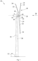
- Figure 1 is a perspective view of an example of a wind turbine 10.
- the wind turbine 10 is a horizontal-axis wind turbine.
- the wind turbine 10 may be a vertical-axis wind turbine.
- the wind turbine 10 includes a tower 15 that extends from a support system 14 on a ground 12, a nacelle 16 mounted on tower 15, and a rotor 18 that is coupled to nacelle 16.
- the rotor 18 includes a rotatable hub 20 and at least one rotor blade 22 coupled to and extending outward from the hub 20.
- the rotor 18 has three rotor blades 22.
- the rotor 18 includes more or less than three rotor blades 22.
- the tower 15 may be fabricated from tubular steel to define a cavity (not shown in figure 1 ) between a support system 14 and the nacelle 16.
- the tower 15 is any suitable type of a tower having any suitable height.
- the tower can be a hybrid tower comprising a portion made of concrete and a tubular steel portion.
- the tower can be a partial or full lattice tower.
- the rotor blades 22 are spaced about the hub 20 to facilitate rotating the rotor 18 to enable kinetic energy to be transferred from the wind into usable mechanical energy, and subsequently, electrical energy.
- the rotor blades 22 are mated to the hub 20 by coupling a blade root portion 24 to the hub 20 at a plurality of load transfer regions 26.
- the load transfer regions 26 may have a hub load transfer region and a blade load transfer region (both not shown in figure 1 ). Loads induced to the rotor blades 22 are transferred to the hub 20 via the load transfer regions 26.
- the rotor 18 As wind strikes the rotor blades 22 from a wind direction 28, the rotor 18 is rotated about a rotor axis 30. As the rotor blades 22 are rotated and subjected to centrifugal forces, the rotor blades 22 are also subjected to various forces and moments. As such, the rotor blades 22 may deflect and/or rotate from a neutral, or non-deflected, position to a deflected position.
- a pitch angle of the rotor blades 22, i.e., an angle that determines an orientation of the rotor blades 22 with respect to the wind direction, may be changed by a pitch system 32 to control the load and power generated by the wind turbine 10 by adjusting an angular position of at least one rotor blade 22 relative to wind vectors. Pitch axes 34 of rotor blades 22 are shown.
- the pitch system 32 may particularly change a pitch angle of the rotor blades 22 such that the angle of attack of (portions of) the rotor blades are reduced, which facilitates reducing a rotational speed and/or facilitates a stall of the rotor 18.
- a blade pitch of each rotor blade 22 is controlled individually by a wind turbine controller 36 or by a pitch control system 80.
- the blade pitch for all rotor blades 22 may be controlled simultaneously by said control systems.
- a yaw direction of the nacelle 16 may be rotated about a yaw axis 38 to position the rotor blades 22 with respect to wind direction 28.
- the wind turbine controller 36 is shown as being centralized within the nacelle 16, however, the wind turbine controller 36 may be a distributed system throughout the wind turbine 10, on the support system 14, within a wind farm, and/or at a remote-control center.
- the wind turbine controller 36 includes a processor 40 configured to perform the methods and/or steps described herein. Further, many of the other components described herein include a processor.
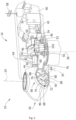
- Figure 2 is an enlarged sectional view of a portion of the wind turbine 10.
- the wind turbine 10 includes the nacelle 16 and the rotor 18 that is rotatably coupled to the nacelle 16. More specifically, the hub 20 of the rotor 18 is rotatably coupled to an electric generator 42 positioned within the nacelle 16 by the main shaft 44, a gearbox 46, a high-speed shaft 48, and a coupling 50.
- the main shaft 44 is disposed at least partially coaxial to a longitudinal axis (not shown) of the nacelle 16.
- a rotation of the main shaft 44 drives the gearbox 46 that subsequently drives the high-speed shaft 48 by translating the relatively slow rotational movement of the rotor 18 and of the main shaft 44 into a relatively fast rotational movement of the high-speed shaft 48.
- the latter is connected to the generator 42 for generating electrical energy with the help of a coupling 50.
- a transformer 90 and/or suitable electronics, switches, and/or inverters may be arranged in the nacelle 16 in order to transform electrical energy generated by the generator 42 having a voltage between 400V to 1000 V into electrical energy having medium voltage (10 - 35 KV). Said electrical energy is conducted via power cables from the nacelle 16 into the tower 15.
- the gearbox 46, generator 42 and transformer 90 may be supported by a main support structure frame of the nacelle 16, optionally embodied as a main frame 52.
- the gearbox 46 may include a gearbox housing that is connected to the main frame 52 by one or more torque arms 103.
- the nacelle 16 also includes a main forward support bearing 60 and a main aft support bearing 62.
- the generator 42 can be mounted to the main frame 52 by decoupling support means 54, in particular in order to prevent vibrations of the generator 42 to be introduced into the main frame 52 and thereby causing a noise emission source.
- the main frame 52 is configured to carry the entire load caused by the weight of the rotor 18 and components of the nacelle 16 and by the wind and rotational loads, and furthermore, to introduce these loads into the tower 15 of the wind turbine 10.
- the rotor shaft 44, generator 42, gearbox 46, high speed shaft 48, coupling 50, and any associated fastening, support, and/or securing device including, but not limited to, support 52, and forward support bearing 60 and aft support bearing 62, are sometimes referred to as a drive train 64.
- the wind turbine may be a direct drive wind turbine without gearbox 46.
- Generator 42 operate at the same rotational speed as the rotor 18 in direct drive wind turbines. They therefore generally have a much larger diameter than generators used in wind turbines having a gearbox 46 for providing a similar amount of power than a wind turbine with a gearbox.
- the nacelle 16 also may include a yaw drive mechanism 56 that may be used to rotate the nacelle 16 and thereby also the rotor 18 about the yaw axis 38 to control the perspective of the rotor blades 22 with respect to the wind direction 28.
- a yaw drive mechanism 56 may be used to rotate the nacelle 16 and thereby also the rotor 18 about the yaw axis 38 to control the perspective of the rotor blades 22 with respect to the wind direction 28.
- the nacelle 16 may also include at least one meteorological measurement system 58 which may include a wind vane and anemometer.
- the meteorological measurement system 58 can provide information to the wind turbine controller 36 that may include wind direction 28 and/or wind speed.
- the pitch system 32 is at least partially arranged as a pitch assembly 66 in the hub 20.
- the pitch assembly 66 includes one or more pitch drive systems 68 and at least one sensor 70.
- Each pitch drive system 68 is coupled to a respective rotor blade 22 (shown in figure 1 ) for modulating the pitch angle of a rotor blade 22 along the pitch axis 34. Only one of three pitch drive systems 68 is shown in figure 2 .
- the pitch assembly 66 includes at least one pitch bearing 72 coupled to hub 20 and to a respective rotor blade 22 (shown in figure 1 ) for rotating the respective rotor blade 22 about the pitch axis 34.
- Pitch drive system 68 is coupled to the wind turbine controller 36 for adjusting the pitch angle of a rotor blade 22 upon receipt of one or more signals from the wind turbine controller 36.
- the pitch assembly 66 may also include one or more pitch control systems 80 for controlling the pitch drive system 68 according to control signals from the wind turbine controller 36, in case of specific prioritized situations and/or during rotor 18 overspeed.
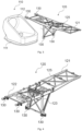
- Figure 3 schematically illustrates an exploded view of a primary frame and a secondary structure of a wind turbine provided.
- the wind turbine comprises a wind turbine tower (not shown) and a primary frame 110 connected to the tower.
- the wind turbine further comprises a secondary structure 120 that is connected to the primary frame 110 and one or more flexible couplings 130 between the primary frame 110 and the secondary structure 120 configured to reduce transmission of deformations from the primary frame to the secondary structure.
- the wind turbine comprises a rotor including a plurality of blades (not shown).
- the rotor is located at a first side of the primary frame 110.
- the secondary structure 120 is connected to the primary frame 110 at a second side of the primary frame 110. The first side is opposite to the second side.
- the first side of the primary frame 110 at which the rotor is arranged may typically be an upwind side of the primary frame 110.
- the second side of the primary frame 110 may thus be the downwind side.
- the first side of the primary frame 110 may be the downwind side
- the second side of the primary frame 110 may be the upwind side.
- the wind turbine comprises one or more flexible couplings 130 between the primary frame 110 and the secondary structure 120.
- the flexible couplings 130 are configured to reduce transmission of deformations from the primary frame 110 to the secondary structure 120.
- the flexible couplings 130 in figure 1 have been schematically illustrated as a rectangular box of broken lines for simplicity. Figures 4 to 6 and the discussion below will provide more details regarding examples of the flexible couplings 130 that may be used.
- the flexible couplings 130 may be or comprise any element that reduces the level of loads and stresses induced from the primary frame 110 to the secondary structure 120 while it withstands the loads acting on the secondary structure 120. Thus, the flexible couplings may provide a secure connection between secondary structure 120 and primary frame 110.
- the flexible couplings 130 may comprise an elastomeric material or a material substantially more flexible than the material from which the secondary structure 120 is manufactured. Additionally, the flexible couplings 130 may comprise a metal spring or a grower washer to allow certain degree of motion between the secondary structure 120 and the central frame 110. In some examples, the flexible couplings 130 may also comprise a sliding mechanism that allows relative displacement between the central frame 110 and the secondary structure 120.
- the primary frame 110 may comprise a base structure 111 including a substantially horizontal plane configured for connecting to a yaw bearing of the tower. Further, the primary frame may also comprise a front structure 112 including a substantially vertical plane configured for connecting to a rotor support structure. Additionally, the secondary structure 120 may be connected to the primary frame 110 at, or near, the base structure 111 and at, or near, the front structure 112.
- the rotor support structure connected to the vertical plane of the primary frame may be a front frame or an intermediate frame.
- the rotor support structure may also be a stator structure of a generator stator.
- the wind turbine may be a direct drive wind turbine. In other examples, the wind turbine according to this example may be a wind turbine with a gearbox.
- the secondary structure 120 may comprise a helipad region 121 configured to support all necessary parts and components to form a helipad.
- a helipad region 121 of a nacelle of a wind turbine is generally a platform on top the nacelle that may be used for supplying and removing parts of components of the wind turbine, and also an area from which personnel may be evacuated.
- a nacelle housing can encompass the frames 110, 120 or part of the frames.
- the secondary structure 120 may additionally comprise other structural components intended to receive other nacelle components.
- Figure 4 schematically illustrates a secondary structure 120 of a wind turbine according to one example.
- the secondary structure 120 comprises a plurality of structural elements 122, 123 configured to be connected to the primary frame of the wind turbine (not shown in this figure).
- At least one of the structural elements 122 e.g. substantially horizontal beams comprises a flexible coupling 130 specifically configured to reduce the transmission of horizontal deformations induced on the primary frame.
- the flexible coupling 130 may have specific flexibility in the horizontal direction to achieve such an effect, i.e. the flexible coupling between primary frame 110 and horizontal beams 122 may have more flexibility in the horizontal direction than in the vertical direction.
- At least another one of the structural elements 123 e.g. vertical struts comprises a flexible coupling 130 specifically configured to reduce the transmission of both horizontal and vertical deformations of the central frame 110 to the secondary structure 120.
- the secondary structure 120 may include a trusswork structure 125.
- the trusswork structure 125 may be designed and manufactured in a variety of ways.
- the trusswork structure 125 may comprise trusses between external beams arranged equidistantly from adjacent trusses.
- the trusses may be metal profiles or metal beams.
- the trusses may be composite or hybrid profiles or beams.
- the trusses may be connected to beams (both external and internal beams) and/or to each other by any fastening element known in the art, i.e. rivets, spot welding, line welding, and others.
- At least one of the flexible couplings 130 is configured to reduce the transmission of deformations and vibrations specifically in a single direction. In some further examples, at least one of the flexible couplings 130 is configured to reduce the transmission of deformations and vibrations in at least two directions.
- the flexible couplings 130 substantially reduce the vibrations transmitted from the central frame 110 to the secondary structure 120 in a frequency range that has a significant influence in the level of stress/damage induced into the secondary frame.
- the frequency range may be between 1Hz and 50Hz.
- Figure 5 illustrates a detailed view of a flexible coupling 130 between a central frame 110 and a secondary structure 120.
- the flexible coupling 130 comprises a first end coupled to a central frame 110, an intermediate portion including an elastomer material 132 and a second end coupled to a secondary structure 120.
- deformations in the central frame 110 may be at least partially absorbed by the elastomer material 132 and the stresses transmitted to the secondary structure 120 may be substantially reduced.
- other type of flexible couplings 130 may be employed for the same purpose, i.e. silentblocks, springs, grower washers, sliding connections and others.
- the flexible coupling 130 illustrated in figure 5 is coupled to a horizontal structural element (with reference numeral 122 in figure 4 ) and has an increased flexibility in a horizontal plane (as compared to e.g. the vertical direction). More relative displacement is allowed in the horizontal plane. Thus, lower stresses are induced into the secondary structure, specifically along the horizontal plane.
- Figure 6 illustrates a perspective view of a flexible coupling 130 standing alone. More precisely, the flexible coupling 130 in figure 6 corresponds to the example of the flexible component coupled to the vertical strut 123 in figure 4 .
- the flexible coupling 130 in figure 6 comprises a first end 135 configured to be connected to a structural element of the secondary structure 120 and a second end 136 configured to be connected to a structural element of the central frame 110. More precisely, the first end 135 may be connected to a substantially vertical structural element 123 of the secondary structure 120, whereas the second end 136 may be connected at, or near, the base structure 111 of the central frame 110 (see figure 3 and 4 ).
- the flexible coupling 130 may comprise more than one device configured for damping vibrations and mitigate the transmission of associated stresses. More specifically, the flexible coupling 130 may comprise two damping devices 133, 134, i.e. two silentblocks.
- the devices 133, 134 may be connected in parallel wherein e.g. a first device 133 allows the relative displacement in two directions, i.e. horizontally and vertically, and a second device 134 supports the weight of the secondary structure and allows the displacement in a second direction, i.e. vertical direction.
- the damping characteristics of each of the devices 133, 134 may be chosen such as to damp deformation or vibrations of different amplitudes and frequencies.
- the devices 133, 134 may be also configured to withstand different maximum loads acting on them.
- the second device 134 may be configured to withstand higher loads than the first device 133, and vice versa.
- Other arrangement of devices may be chosen to mitigate stresses and vibrations of certain amplitudes, frequencies and direction of propagation.
- damping devices may be arranged in series, i.e. a load path inevitable passes through both of the damping devices.
- parallel load paths between the primary frame and secondary structure may be provided.
- the secondary structure 120 may comprise flexible couplings 130 in all structural elements that are coupled to the central frame 110.
- the secondary structure 120 may comprise flexible couplings 130 in some of the structural elements that are coupled to the central frame 110.
- other types of connections between the central frame 110 and the secondary structure 120 may be employed, i.e. partially rotatable connections.
- Figure 7 is a flow diagram of an example of a method 700 for refurbishing a secondary structure 120 of a wind turbine 10 according to the present disclosure.
- the method 700 comprises, at block 701, cutting a piece of a structural element 123, 122 of the secondary structure 120 that is be connected to a primary frame 110. Further, the method 700 also comprises, at block 702, providing a flexible coupling 130 in a portion of the structural element 123, 122 in replacement of the cut piece.
- the method 700 may further comprise coupling the secondary structure 120 to the primary frame 110 through the flexible coupling 130.
- the flexible coupling as in other examples of the present disclosure is specifically configured to limit the transmission of deformations from the primary frame 110 to the secondary structure.
- the method 700 may also comprise supporting the structural element 123, 122 since before the cutting 701 until the moment of coupling to the primary frame, or even until after.
- supporting the structural element 123, 122 may be performed using one or more jacks, e.g. hydraulic jacks or any other suitable system. Additionally, the steps of cutting 701 a piece of a structural element 123, 122 and providing 702 a flexible coupling 130 may be performed in all structural elements configured to be connected to the central frame 110. In such a case, a flexible coupling is provided at each of connection of the primary frame to the secondary structure.
- a method for reducing oscillations in the secondary structure is provided.
- the secondary structure is connected to a primary frame of a wind turbine.
- deformations of the primary frame are partially absorbed by the flexible couplings, and at least some of the oscillations of the primary frame are not transmitted to the secondary structure.
- Examples of such a method for reducing oscillations in the secondary structure may use any of the features of the various examples of figures 3 - 6 either in isolation or in combination.
Landscapes
- Engineering & Computer Science (AREA)
- General Engineering & Computer Science (AREA)
- Chemical & Material Sciences (AREA)
- Combustion & Propulsion (AREA)
- Mechanical Engineering (AREA)
- Life Sciences & Earth Sciences (AREA)
- Sustainable Development (AREA)
- Sustainable Energy (AREA)
- Physics & Mathematics (AREA)
- Acoustics & Sound (AREA)
- Aviation & Aerospace Engineering (AREA)
- Wind Motors (AREA)
Abstract
Description
- The present disclosure relates to wind turbines comprising a flexible coupling. More specifically, the present disclosure relates to wind turbines comprising flexible couplings between a primary frame and a secondary structure. The present disclosure also relates to secondary structures and methods for refurbishing a secondary structure of a wind turbine.
- Modern wind turbines are commonly used to supply electricity into the electrical grid. Wind turbines of this kind generally comprise a tower, a nacelle and a rotor. The rotor, which typically comprises a hub and a plurality of blades, is set into rotation under the influence of the wind on the blades. This rotation is normally transmitted to a generator, either directly ("directly driven") or through the use of a gearbox. This way, the generator produces electricity which can be supplied to the electrical grid.
- In order to extract more energy from the wind, the size of the rotor diameter has increased significantly over the last years by increasing the dimensions of the wind turbine blades. The larger size of the blades implies higher aerodynamic loads that are transferred through the blades into the rotor, nacelle and tower. For example, larger rotor blades may experience increased stresses, deformations and vibrations due to higher aerodynamical moments and others, and these are transmitted to the rotor hub and to the nacelle. The transmitted stresses, deformations and vibrations may lead to challenging design constraints, both in terms of extreme events and fatigue life requirements.
- The likelihood of structural failure in wind turbine components, such as a frames of the wind turbine nacelle, is generally compensated by the manufacture of bigger, heavier and more resistant components. In the case of the nacelle frames, this approach leads to an increase in material costs, and a considerable increase in the overall weight of the nacelle. Further, the installation of bigger frames may require providing more robust tower structures so that the tower can safely withstand the nacelle and the loads acting on it. Even if bigger and heavier frames are used, they can still suffer and ultimately fail due to dynamic loads.
- The present disclosure provides examples of systems and methods that avoid or reduce premature failure of frames of the wind turbine nacelle and that overcome some of the drawbacks of existing approaches.
- In a first aspect, a wind turbine is provided. The wind turbine comprises a wind turbine tower, and a nacelle including a primary frame, wherein the primary frame is connected to the tower. The wind turbine further comprises a secondary structure that is connected to the primary frame and one or more flexible couplings between the primary frame and the secondary structure configured to reduce transmission of deformations from the primary frame to the secondary structure.
- According to this first aspect, the one or more flexible couplings installed between the primary frame and the secondary structure of the wind turbine reduce the magnitude of the deformations transferred from the primary frame to the secondary structure, thus reducing the level of stress induced into the secondary structure. The primary frame may suffer asymmetric deformations due to asymmetric loads on the wind turbine rotor. These asymmetric deformations of the primary frame, if transferred to the secondary structure, could lead to significant stresses and strains in the secondary structure. The flexible couplings can avoid or significantly reduce those stresses. Thus, the secondary structure may be manufactured taking into account a narrower load envelope compared with a scenario where the flexible coupling is not provided. As a result, the secondary structure may be manufactured as a lighter frame and may have a simpler structure.
- In another aspect, a method of refurbishing a secondary structure of a wind turbine, that is connected to a primary frame is provided. The method comprises cutting a piece of a structural element of the secondary structure that is connected to the primary frame and providing a flexible coupling in a portion of the structural element in replacement of the cut piece. The method then further comprises coupling the secondary structure to the primary frame through the flexible coupling, wherein the flexible coupling is configured to reduce transmission of deformations of the primary frame to the secondary structure.
- The method according to this aspect allows refurbishing a secondary structure of a wind turbine in wind turbines that are already in operation. Particularly, the method allows considerably increasing the service life of nacelle frame assemblies.
- In yet a further aspect, a secondary structure of a wind turbine is provided. The secondary structure comprises a plurality of structural elements configured to be connected to a primary frame of the wind turbine. At least one of the structural elements comprises a flexible coupling configured to reduce the transmission of horizontal deformations of the primary frame to the secondary frame. And at least another one of the structural elements comprises a flexible coupling configured to reduce the transmission of both horizontal and vertical deformations of the primary frame to the secondary structure.
- And in yet a further aspect, a method for reducing oscillations in a secondary structure is provided. The secondary structure is connected to a primary frame of a wind turbine. The method comprises providing one or more flexible couplings between the primary frame and the secondary structure, such that deformations of the primary frame are partially absorbed by the flexible couplings, and at least some of the oscillations of the primary frame are not transmitted to the secondary structure.
- Throughout the present disclosure, a primary frame is to be regarded as a load carrying structure arranged in the main load path between the wind turbine rotor and wind turbine tower. I.e. the primary frame is the load carrying structure that transmits the loads to the tower, generally through a yaw bearing. A primary frame may also be called a central frame or a main frame.
- A secondary structure as used throughout the present disclosure may be regarded as a (load-carrying) structure that is not arranged in the main load path. The secondary structure may be used for accommodating or housing auxiliary systems such as auxiliary mechanical or electrical systems, and in particular the power conversion assembly or components thereof.
- Throughout the present disclosure, a vertical direction should be understood as a direction substantially parallel to the direction of gravity, and a horizontal direction should be understood as a direction substantially parallel to ground and perpendicular to the vertical direction.
- Non-limiting examples of the present disclosure will be described in the following, with reference to the appended drawings, in which:
-
Figure 1 illustrates a perspective view of a wind turbine according to one example; -
Figure 2 illustrates a detailed, internal view of a nacelle of a wind turbine according to one example; -
Figure 3 schematically illustrates an exploded view of a central frame and secondary structure according to another example; -
Figure 4 schematically illustrates a perspective view of a secondary structure according to another example; -
Figure 5 is a detailed view of a flexible coupling between a central frame and a secondary structure according to one example; -
Figure 6 is a perspective view of a flexible coupling standing alone according to one example; and -
Figure 7 is a block diagram of a method for refurbishing a wind turbine according to one example. - Reference now will be made in detail to embodiments of the present disclosure, one or more examples of which are illustrated in the drawings. Each example is provided by way of explanation only, not as a limitation. In fact, it will be apparent to those skilled in the art that various modifications and variations can be made in the present disclosure. For instance, features illustrated or described as part of one embodiment can be used with another embodiment to yield a still further embodiment. Thus, it is intended that the present disclosure covers such modifications and variations as come within the scope of the appended claims and their equivalents.
-
Figure 1 is a perspective view of an example of awind turbine 10. In the example, thewind turbine 10 is a horizontal-axis wind turbine. Alternatively, thewind turbine 10 may be a vertical-axis wind turbine. In the example, thewind turbine 10 includes atower 15 that extends from asupport system 14 on aground 12, anacelle 16 mounted ontower 15, and arotor 18 that is coupled tonacelle 16. Therotor 18 includes arotatable hub 20 and at least onerotor blade 22 coupled to and extending outward from thehub 20. In the example, therotor 18 has threerotor blades 22. In an alternative embodiment, therotor 18 includes more or less than threerotor blades 22. Thetower 15 may be fabricated from tubular steel to define a cavity (not shown infigure 1 ) between asupport system 14 and thenacelle 16. In an alternative embodiment, thetower 15 is any suitable type of a tower having any suitable height. According to an alternative, the tower can be a hybrid tower comprising a portion made of concrete and a tubular steel portion. Also, the tower can be a partial or full lattice tower. - The
rotor blades 22 are spaced about thehub 20 to facilitate rotating therotor 18 to enable kinetic energy to be transferred from the wind into usable mechanical energy, and subsequently, electrical energy. Therotor blades 22 are mated to thehub 20 by coupling ablade root portion 24 to thehub 20 at a plurality ofload transfer regions 26. Theload transfer regions 26 may have a hub load transfer region and a blade load transfer region (both not shown infigure 1 ). Loads induced to therotor blades 22 are transferred to thehub 20 via theload transfer regions 26. - As wind strikes the
rotor blades 22 from awind direction 28, therotor 18 is rotated about arotor axis 30. As therotor blades 22 are rotated and subjected to centrifugal forces, therotor blades 22 are also subjected to various forces and moments. As such, therotor blades 22 may deflect and/or rotate from a neutral, or non-deflected, position to a deflected position. - Moreover, a pitch angle of the
rotor blades 22, i.e., an angle that determines an orientation of therotor blades 22 with respect to the wind direction, may be changed by apitch system 32 to control the load and power generated by thewind turbine 10 by adjusting an angular position of at least onerotor blade 22 relative to wind vectors. Pitch axes 34 ofrotor blades 22 are shown. During operation of thewind turbine 10, thepitch system 32 may particularly change a pitch angle of therotor blades 22 such that the angle of attack of (portions of) the rotor blades are reduced, which facilitates reducing a rotational speed and/or facilitates a stall of therotor 18. - In the example, a blade pitch of each
rotor blade 22 is controlled individually by awind turbine controller 36 or by apitch control system 80. Alternatively, the blade pitch for allrotor blades 22 may be controlled simultaneously by said control systems. - Further, in the example, as the
wind direction 28 changes, a yaw direction of thenacelle 16 may be rotated about ayaw axis 38 to position therotor blades 22 with respect to winddirection 28. - In the example, the
wind turbine controller 36 is shown as being centralized within thenacelle 16, however, thewind turbine controller 36 may be a distributed system throughout thewind turbine 10, on thesupport system 14, within a wind farm, and/or at a remote-control center. Thewind turbine controller 36 includes aprocessor 40 configured to perform the methods and/or steps described herein. Further, many of the other components described herein include a processor. -
Figure 2 is an enlarged sectional view of a portion of thewind turbine 10. In the example, thewind turbine 10 includes thenacelle 16 and therotor 18 that is rotatably coupled to thenacelle 16. More specifically, thehub 20 of therotor 18 is rotatably coupled to anelectric generator 42 positioned within thenacelle 16 by themain shaft 44, agearbox 46, a high-speed shaft 48, and acoupling 50. In the example, themain shaft 44 is disposed at least partially coaxial to a longitudinal axis (not shown) of thenacelle 16. A rotation of themain shaft 44 drives thegearbox 46 that subsequently drives the high-speed shaft 48 by translating the relatively slow rotational movement of therotor 18 and of themain shaft 44 into a relatively fast rotational movement of the high-speed shaft 48. The latter is connected to thegenerator 42 for generating electrical energy with the help of acoupling 50. Furthermore, atransformer 90 and/or suitable electronics, switches, and/or inverters may be arranged in thenacelle 16 in order to transform electrical energy generated by thegenerator 42 having a voltage between 400V to 1000 V into electrical energy having medium voltage (10 - 35 KV). Said electrical energy is conducted via power cables from thenacelle 16 into thetower 15. - The
gearbox 46,generator 42 andtransformer 90 may be supported by a main support structure frame of thenacelle 16, optionally embodied as amain frame 52. Thegearbox 46 may include a gearbox housing that is connected to themain frame 52 by one ormore torque arms 103. In the example, thenacelle 16 also includes a main forward support bearing 60 and a mainaft support bearing 62. Furthermore, thegenerator 42 can be mounted to themain frame 52 by decoupling support means 54, in particular in order to prevent vibrations of thegenerator 42 to be introduced into themain frame 52 and thereby causing a noise emission source. - Optionally, the
main frame 52 is configured to carry the entire load caused by the weight of therotor 18 and components of thenacelle 16 and by the wind and rotational loads, and furthermore, to introduce these loads into thetower 15 of thewind turbine 10. Therotor shaft 44,generator 42,gearbox 46,high speed shaft 48,coupling 50, and any associated fastening, support, and/or securing device including, but not limited to,support 52, and forward support bearing 60 and aft support bearing 62, are sometimes referred to as adrive train 64. - In some examples, the wind turbine may be a direct drive wind turbine without
gearbox 46.Generator 42 operate at the same rotational speed as therotor 18 in direct drive wind turbines. They therefore generally have a much larger diameter than generators used in wind turbines having agearbox 46 for providing a similar amount of power than a wind turbine with a gearbox. - The
nacelle 16 also may include ayaw drive mechanism 56 that may be used to rotate thenacelle 16 and thereby also therotor 18 about theyaw axis 38 to control the perspective of therotor blades 22 with respect to thewind direction 28. - For positioning the
nacelle 16 appropriately with respect to thewind direction 28, thenacelle 16 may also include at least onemeteorological measurement system 58 which may include a wind vane and anemometer. Themeteorological measurement system 58 can provide information to thewind turbine controller 36 that may includewind direction 28 and/or wind speed. In the example, thepitch system 32 is at least partially arranged as apitch assembly 66 in thehub 20. Thepitch assembly 66 includes one or morepitch drive systems 68 and at least onesensor 70. Eachpitch drive system 68 is coupled to a respective rotor blade 22 (shown infigure 1 ) for modulating the pitch angle of arotor blade 22 along thepitch axis 34. Only one of threepitch drive systems 68 is shown infigure 2 . - In the example, the
pitch assembly 66 includes at least one pitch bearing 72 coupled tohub 20 and to a respective rotor blade 22 (shown infigure 1 ) for rotating therespective rotor blade 22 about thepitch axis 34. -
Pitch drive system 68 is coupled to thewind turbine controller 36 for adjusting the pitch angle of arotor blade 22 upon receipt of one or more signals from thewind turbine controller 36. Thepitch assembly 66 may also include one or morepitch control systems 80 for controlling thepitch drive system 68 according to control signals from thewind turbine controller 36, in case of specific prioritized situations and/or duringrotor 18 overspeed. -
Figure 3 schematically illustrates an exploded view of a primary frame and a secondary structure of a wind turbine provided. The wind turbine comprises a wind turbine tower (not shown) and aprimary frame 110 connected to the tower. The wind turbine further comprises asecondary structure 120 that is connected to theprimary frame 110 and one or moreflexible couplings 130 between theprimary frame 110 and thesecondary structure 120 configured to reduce transmission of deformations from the primary frame to the secondary structure. - The wind turbine comprises a rotor including a plurality of blades (not shown). In this example, the rotor is located at a first side of the
primary frame 110. Thesecondary structure 120 is connected to theprimary frame 110 at a second side of theprimary frame 110. The first side is opposite to the second side. - The first side of the
primary frame 110 at which the rotor is arranged may typically be an upwind side of theprimary frame 110. The second side of theprimary frame 110 may thus be the downwind side. In other examples, the first side of theprimary frame 110 may be the downwind side, and the second side of theprimary frame 110 may be the upwind side. - The wind turbine comprises one or more
flexible couplings 130 between theprimary frame 110 and thesecondary structure 120. Theflexible couplings 130 are configured to reduce transmission of deformations from theprimary frame 110 to thesecondary structure 120. Note that theflexible couplings 130 infigure 1 have been schematically illustrated as a rectangular box of broken lines for simplicity.Figures 4 to 6 and the discussion below will provide more details regarding examples of theflexible couplings 130 that may be used. - The
flexible couplings 130 may be or comprise any element that reduces the level of loads and stresses induced from theprimary frame 110 to thesecondary structure 120 while it withstands the loads acting on thesecondary structure 120. Thus, the flexible couplings may provide a secure connection betweensecondary structure 120 andprimary frame 110. - In examples, the
flexible couplings 130 may comprise an elastomeric material or a material substantially more flexible than the material from which thesecondary structure 120 is manufactured. Additionally, theflexible couplings 130 may comprise a metal spring or a grower washer to allow certain degree of motion between thesecondary structure 120 and thecentral frame 110. In some examples, theflexible couplings 130 may also comprise a sliding mechanism that allows relative displacement between thecentral frame 110 and thesecondary structure 120. - In some examples, such as in
figure 3 , theprimary frame 110 may comprise abase structure 111 including a substantially horizontal plane configured for connecting to a yaw bearing of the tower. Further, the primary frame may also comprise afront structure 112 including a substantially vertical plane configured for connecting to a rotor support structure. Additionally, thesecondary structure 120 may be connected to theprimary frame 110 at, or near, thebase structure 111 and at, or near, thefront structure 112. - In further examples, the rotor support structure connected to the vertical plane of the primary frame may be a front frame or an intermediate frame. Depending on the arrangement of the wind turbine components, the rotor support structure may also be a stator structure of a generator stator.
- In some examples, the wind turbine may be a direct drive wind turbine. In other examples, the wind turbine according to this example may be a wind turbine with a gearbox.
- As can be seen in
figure 3 , thesecondary structure 120 may comprise ahelipad region 121 configured to support all necessary parts and components to form a helipad. Ahelipad region 121 of a nacelle of a wind turbine is generally a platform on top the nacelle that may be used for supplying and removing parts of components of the wind turbine, and also an area from which personnel may be evacuated. It will be clear that a nacelle housing can encompass theframes secondary structure 120 may additionally comprise other structural components intended to receive other nacelle components. -
Figure 4 schematically illustrates asecondary structure 120 of a wind turbine according to one example. Thesecondary structure 120 comprises a plurality ofstructural elements - At least one of the
structural elements 122, e.g. substantially horizontal beams comprises aflexible coupling 130 specifically configured to reduce the transmission of horizontal deformations induced on the primary frame. Theflexible coupling 130 may have specific flexibility in the horizontal direction to achieve such an effect, i.e. the flexible coupling betweenprimary frame 110 andhorizontal beams 122 may have more flexibility in the horizontal direction than in the vertical direction. - Further, at least another one of the
structural elements 123, e.g. vertical struts comprises aflexible coupling 130 specifically configured to reduce the transmission of both horizontal and vertical deformations of thecentral frame 110 to thesecondary structure 120. - Also illustrated in
figure 4 , thesecondary structure 120 may include atrusswork structure 125. Thetrusswork structure 125 may be designed and manufactured in a variety of ways. In some examples, thetrusswork structure 125 may comprise trusses between external beams arranged equidistantly from adjacent trusses. The trusses may be metal profiles or metal beams. In other examples, the trusses may be composite or hybrid profiles or beams. The trusses may be connected to beams (both external and internal beams) and/or to each other by any fastening element known in the art, i.e. rivets, spot welding, line welding, and others. - In the example illustrated in
figure 4 , at least one of theflexible couplings 130 may comprise a silentblock. Examples of silentblocks will be discussed in more detail in relation withfigures 5 and 6 . - In some examples, at least one of the
flexible couplings 130 is configured to reduce the transmission of deformations and vibrations specifically in a single direction. In some further examples, at least one of theflexible couplings 130 is configured to reduce the transmission of deformations and vibrations in at least two directions. - Additionally, the
flexible couplings 130 substantially reduce the vibrations transmitted from thecentral frame 110 to thesecondary structure 120 in a frequency range that has a significant influence in the level of stress/damage induced into the secondary frame. Specifically, the frequency range may be between 1Hz and 50Hz. -
Figure 5 illustrates a detailed view of aflexible coupling 130 between acentral frame 110 and asecondary structure 120. In the above case, theflexible coupling 130 comprises a first end coupled to acentral frame 110, an intermediate portion including anelastomer material 132 and a second end coupled to asecondary structure 120. Thus, deformations in thecentral frame 110 may be at least partially absorbed by theelastomer material 132 and the stresses transmitted to thesecondary structure 120 may be substantially reduced. As previously discussed, other type offlexible couplings 130 may be employed for the same purpose, i.e. silentblocks, springs, grower washers, sliding connections and others. - Silentblocks may be formed by an annular cylinder of flexible material inside a considerably rigid casing, i.e. a metallic casing. The flexible material may be connected between two ends of the casing, providing a flexible coupling between the respective ends. In some examples, the silentblocks may comprise an internal crush tube configured to protect the silentblocks from being crushed by the fastener connections that hold it in place. In further examples, the silentblocks may allow sliding at the interface between one fastener connection and the flexible material.
- The
flexible coupling 130 illustrated infigure 5 is coupled to a horizontal structural element (withreference numeral 122 infigure 4 ) and has an increased flexibility in a horizontal plane (as compared to e.g. the vertical direction). More relative displacement is allowed in the horizontal plane. Thus, lower stresses are induced into the secondary structure, specifically along the horizontal plane. -
Figure 6 illustrates a perspective view of aflexible coupling 130 standing alone. More precisely, theflexible coupling 130 infigure 6 corresponds to the example of the flexible component coupled to thevertical strut 123 infigure 4 . Theflexible coupling 130 infigure 6 comprises afirst end 135 configured to be connected to a structural element of thesecondary structure 120 and asecond end 136 configured to be connected to a structural element of thecentral frame 110. More precisely, thefirst end 135 may be connected to a substantially verticalstructural element 123 of thesecondary structure 120, whereas thesecond end 136 may be connected at, or near, thebase structure 111 of the central frame 110 (seefigure 3 and 4 ). -
Figure 6 also shows that theflexible coupling 130 may comprise more than one device configured for damping vibrations and mitigate the transmission of associated stresses. More specifically, theflexible coupling 130 may comprise two dampingdevices devices first device 133 allows the relative displacement in two directions, i.e. horizontally and vertically, and asecond device 134 supports the weight of the secondary structure and allows the displacement in a second direction, i.e. vertical direction. The damping characteristics of each of thedevices devices second device 134 may be configured to withstand higher loads than thefirst device 133, and vice versa. Other arrangement of devices may be chosen to mitigate stresses and vibrations of certain amplitudes, frequencies and direction of propagation. - In further examples, two or more of such damping devices may be arranged in series, i.e. a load path inevitable passes through both of the damping devices. In a parallel arrangement, parallel load paths between the primary frame and secondary structure may be provided.
- In some additional examples, the
secondary structure 120 may compriseflexible couplings 130 in all structural elements that are coupled to thecentral frame 110. Alternatively, thesecondary structure 120 may compriseflexible couplings 130 in some of the structural elements that are coupled to thecentral frame 110. In this case, other types of connections between thecentral frame 110 and thesecondary structure 120 may be employed, i.e. partially rotatable connections. -
Figure 7 is a flow diagram of an example of amethod 700 for refurbishing asecondary structure 120 of awind turbine 10 according to the present disclosure. Themethod 700 comprises, atblock 701, cutting a piece of astructural element secondary structure 120 that is be connected to aprimary frame 110. Further, themethod 700 also comprises, atblock 702, providing aflexible coupling 130 in a portion of thestructural element - The
method 700 may further comprise coupling thesecondary structure 120 to theprimary frame 110 through theflexible coupling 130. The flexible coupling, as in other examples of the present disclosure is specifically configured to limit the transmission of deformations from theprimary frame 110 to the secondary structure. - Further, the
method 700 may also comprise supporting thestructural element - In some examples, supporting the
structural element structural element flexible coupling 130 may be performed in all structural elements configured to be connected to thecentral frame 110. In such a case, a flexible coupling is provided at each of connection of the primary frame to the secondary structure. - Note that some of the technical features described in relation with the wind turbine, the secondary structure and the flexible couplings of the examples of
figures 3 - 6 may be included in themethod 700 for refurbishing a wind turbine, and vice versa. - With the method of refurbishing, at the same time, a method for reducing oscillations in the secondary structure is provided. The secondary structure is connected to a primary frame of a wind turbine. By providing one or more flexible couplings between the primary frame and the secondary structure, deformations of the primary frame are partially absorbed by the flexible couplings, and at least some of the oscillations of the primary frame are not transmitted to the secondary structure.
- Examples of such a method for reducing oscillations in the secondary structure may use any of the features of the various examples of
figures 3 - 6 either in isolation or in combination. - This written description uses examples to disclose the present teaching, including the preferred embodiments, and also to enable any person skilled in the art to practice it, including making and using any devices or systems and performing any incorporated methods. The patentable scope is defined by the claims, and may include other examples that occur to those skilled in the art. Such other examples are intended to be within the scope of the claims if they have structural elements that do not differ from the literal language of the claims, or if they include equivalent structural elements with insubstantial differences from the literal languages of the claims. Aspects from the various embodiments described, as well as other known equivalents for each such aspects, can be mixed and matched by one of ordinary skill in the art to construct additional embodiments and techniques in accordance with principles of this application. If reference signs related to drawings are placed in parentheses in a claim, they are solely for attempting to increase the intelligibility of the claim, and shall not be construed as limiting the scope of the claim.
Claims (15)
- A wind turbine (10) comprising:a wind turbine tower (15);a nacelle including a primary frame (110), the primary frame being connected to the tower (15);a secondary structure (120) connected to the primary frame (110); andone or more flexible couplings (130) between the primary frame (110) and the secondary structure (120) configured to reduce transmission of deformations from the primary frame (110) to the secondary structure (120).
- The wind turbine of claim 1, further comprising a rotor (18) having a plurality of blades (22) at a first side of the primary frame (110) and wherein the secondary structure (120) is arranged at a second side of the primary frame, the second side being opposite to the first side.
- The wind turbine (10) of claim 1 or 2, wherein the primary frame (110) comprises a base structure (111) including a substantially horizontal plane configured for connecting to a yaw bearing of the wind turbine tower, and a front structure (112) including a substantially vertical plane configured for connecting to a rotor support structure, and wherein the secondary structure (120) is connected to the primary frame (110) at or near the base structure (111) and at or near the front structure (112).
- The wind turbine (10) of claim 3, wherein the rotor support structure is a front frame or an intermediate frame.
- The wind turbine (10) of claim 3, wherein the rotor support structure is a stator structure of a generator.
- The wind turbine (10) of any of claims 1 - 5, wherein the secondary structure (120) is configured to accommodate power conversion components, and/or other electrical or mechanical auxiliary systems.
- The wind turbine (10) of any of claims 1 - 6, wherein the secondary structure (120) is configured to support a helipad (121).
- The wind turbine (10) of any of claims 1 - 7, wherein the secondary structure (120) includes a trusswork structure (125).
- The wind turbine (10) according to any of claims 1 - 8, wherein at least one of the flexible couplings (130) between the primary frame (110) and the secondary structure (120) comprises an elastomeric material.
- The wind turbine (10) according to claim 9, wherein at least one of the flexible couplings (130) comprises a silentblock (132, 133).
- The wind turbine (10) according to any of claims 1 - 10, wherein at least one of the flexible couplings (130) comprises a sliding mechanism that allows relative displacement between the primary frame (110) and the secondary structure (120).
- The wind turbine (10) according to any of claims 1 - 11, wherein at least one of the flexible couplings (130) reduces the transmission of deformations in at least two directions.
- A method (700) for refurbishing a secondary structure (120) of a wind turbine (10), that is connected to a primary frame (110) of the wind turbine (10), the method (700) comprising:cutting (701) a piece of a structural element (123, 124) of the secondary structure (120) that is connected to the primary frame (110); andproviding (702) a flexible coupling (130) in a portion of the structural element (123, 124) in replacement of the cut piece; andcoupling the secondary structure (120) to the primary frame (110) through the flexible coupling (130), whereinthe flexible coupling is configured to reduce transmission of deformations of the primary frame (110) to the secondary structure (120).
- The method (700) according to claim 13, wherein the method (700) comprises providing a flexible coupling at each point of connection of the primary frame (110) to the secondary structure (120).
- The method (700) according to claim 13 or 14, wherein the method (700) further comprises supporting the structural element (123, 124) from before the cutting (701) until the coupling.
Priority Applications (7)
| Application Number | Priority Date | Filing Date | Title |
|---|---|---|---|
| PL22382350.1T PL4261404T3 (en) | 2022-04-12 | 2022-04-12 | Wind turbine frame with flexible coupling |
| EP22382350.1A EP4261404B1 (en) | 2022-04-12 | 2022-04-12 | Wind turbine frame with flexible coupling |
| ES22382350T ES3034311T3 (en) | 2022-04-12 | 2022-04-12 | Wind turbine frame with flexible coupling |
| JP2023061080A JP2023156245A (en) | 2022-04-12 | 2023-04-05 | Wind turbine frame with flexible coupling |
| KR1020230045936A KR20230146463A (en) | 2022-04-12 | 2023-04-07 | Wind turbine frame with flexible coupling |
| US18/297,859 US20230323860A1 (en) | 2022-04-12 | 2023-04-10 | Wind turbine frame with flexible coupling |
| CN202310380636.2A CN116906258A (en) | 2022-04-12 | 2023-04-11 | Wind turbine frame with flexible coupling |
Applications Claiming Priority (1)
| Application Number | Priority Date | Filing Date | Title |
|---|---|---|---|
| EP22382350.1A EP4261404B1 (en) | 2022-04-12 | 2022-04-12 | Wind turbine frame with flexible coupling |
Publications (2)
| Publication Number | Publication Date |
|---|---|
| EP4261404A1 true EP4261404A1 (en) | 2023-10-18 |
| EP4261404B1 EP4261404B1 (en) | 2025-04-09 |
Family
ID=81307893
Family Applications (1)
| Application Number | Title | Priority Date | Filing Date |
|---|---|---|---|
| EP22382350.1A Active EP4261404B1 (en) | 2022-04-12 | 2022-04-12 | Wind turbine frame with flexible coupling |
Country Status (7)
| Country | Link |
|---|---|
| US (1) | US20230323860A1 (en) |
| EP (1) | EP4261404B1 (en) |
| JP (1) | JP2023156245A (en) |
| KR (1) | KR20230146463A (en) |
| CN (1) | CN116906258A (en) |
| ES (1) | ES3034311T3 (en) |
| PL (1) | PL4261404T3 (en) |
Families Citing this family (1)
| Publication number | Priority date | Publication date | Assignee | Title |
|---|---|---|---|---|
| US20250243849A1 (en) * | 2024-01-31 | 2025-07-31 | Kodair Wind Designs Limited | Wind turbine nacelle |
Citations (5)
| Publication number | Priority date | Publication date | Assignee | Title |
|---|---|---|---|---|
| DE102008046210A1 (en) * | 2008-09-08 | 2010-03-18 | Powerwind Gmbh | Support frame for generator of wind turbine, has four on four interconnected relays, and elongated carrier, where connection points are provided between sections extending into frame-level |
| WO2010069315A2 (en) * | 2008-12-16 | 2010-06-24 | Vestas Wind Systems A/S | Wind turbine nacelle |
| US20100314884A1 (en) * | 2007-12-21 | 2010-12-16 | Vestas Wind Systems A/S | Wind turbine, a method for reducing noise emission from a wind turbine tower and use of a wind turbine |
| EP2899394A1 (en) * | 2014-01-22 | 2015-07-29 | Alstom Renovables España, S.L. | Wind turbine with damping |
| EP3453867A1 (en) * | 2017-09-06 | 2019-03-13 | Siemens Gamesa Renewable Energy A/S | Wind turbine nacelle platform structure |
Family Cites Families (1)
| Publication number | Priority date | Publication date | Assignee | Title |
|---|---|---|---|---|
| EP4012173B1 (en) * | 2020-12-08 | 2025-02-26 | General Electric Renovables España S.L. | A system for a tower segment of a tower, a respective tower segment, and a wind turbine having a tower segment |
-
2022
- 2022-04-12 ES ES22382350T patent/ES3034311T3/en active Active
- 2022-04-12 PL PL22382350.1T patent/PL4261404T3/en unknown
- 2022-04-12 EP EP22382350.1A patent/EP4261404B1/en active Active
-
2023
- 2023-04-05 JP JP2023061080A patent/JP2023156245A/en active Pending
- 2023-04-07 KR KR1020230045936A patent/KR20230146463A/en active Pending
- 2023-04-10 US US18/297,859 patent/US20230323860A1/en active Pending
- 2023-04-11 CN CN202310380636.2A patent/CN116906258A/en active Pending
Patent Citations (5)
| Publication number | Priority date | Publication date | Assignee | Title |
|---|---|---|---|---|
| US20100314884A1 (en) * | 2007-12-21 | 2010-12-16 | Vestas Wind Systems A/S | Wind turbine, a method for reducing noise emission from a wind turbine tower and use of a wind turbine |
| DE102008046210A1 (en) * | 2008-09-08 | 2010-03-18 | Powerwind Gmbh | Support frame for generator of wind turbine, has four on four interconnected relays, and elongated carrier, where connection points are provided between sections extending into frame-level |
| WO2010069315A2 (en) * | 2008-12-16 | 2010-06-24 | Vestas Wind Systems A/S | Wind turbine nacelle |
| EP2899394A1 (en) * | 2014-01-22 | 2015-07-29 | Alstom Renovables España, S.L. | Wind turbine with damping |
| EP3453867A1 (en) * | 2017-09-06 | 2019-03-13 | Siemens Gamesa Renewable Energy A/S | Wind turbine nacelle platform structure |
Also Published As
| Publication number | Publication date |
|---|---|
| JP2023156245A (en) | 2023-10-24 |
| PL4261404T3 (en) | 2025-07-28 |
| ES3034311T3 (en) | 2025-08-14 |
| CN116906258A (en) | 2023-10-20 |
| KR20230146463A (en) | 2023-10-19 |
| US20230323860A1 (en) | 2023-10-12 |
| EP4261404B1 (en) | 2025-04-09 |
Similar Documents
| Publication | Publication Date | Title |
|---|---|---|
| CN101943127B (en) | Wind collecting vertical type wind power generating system | |
| KR101143784B1 (en) | Tower for a windmill and wind power generator | |
| US10830204B2 (en) | Counterweight system for balanced hub wind turbine blade installation | |
| WO2009126696A1 (en) | Wind-driven generation of power | |
| US12006910B2 (en) | Assemblies for wind turbines and methods | |
| US20230323860A1 (en) | Wind turbine frame with flexible coupling | |
| US11946444B2 (en) | Wind turbine blades, wind turbine blade assemblies and related methods | |
| US12018645B2 (en) | Device for aligning holes | |
| WO2020047112A1 (en) | Counterweight assembly for use during single blade installation of a wind turbine | |
| US20210222680A1 (en) | System and method for repairing a gearbox of a wind turbine uptower | |
| EP4012173A1 (en) | A system for a tower segment of a tower, a respective tower segment, and a wind turbine having a tower segment | |
| KR102473253B1 (en) | Rotor bearing housing, and wind power plant with rotor bearing housing | |
| US12071922B2 (en) | Wind turbine blade assembly and methods | |
| US11788510B2 (en) | Nacelle cover panel | |
| US10550826B2 (en) | External platform assembly for wind turbine repairs | |
| US12497952B2 (en) | Couplings and auxiliary components for wind turbines, and associated methods | |
| US20220128037A1 (en) | Nacelle for a wind turbine | |
| US20250003396A1 (en) | Methods for extracting transformers of a nacelle of a wind turbine | |
| US12601325B2 (en) | Current transfer elements, electrical machines and wind turbines comprising such current transfer elements | |
| WO2025247492A1 (en) | Methods, sets and blades for installation of a wind turbine blade | |
| WO2025247493A1 (en) | Methods for installing wind turbine blades |
Legal Events
| Date | Code | Title | Description |
|---|---|---|---|
| PUAI | Public reference made under article 153(3) epc to a published international application that has entered the european phase |
Free format text: ORIGINAL CODE: 0009012 |
|
| STAA | Information on the status of an ep patent application or granted ep patent |
Free format text: STATUS: THE APPLICATION HAS BEEN PUBLISHED |
|
| AK | Designated contracting states |
Kind code of ref document: A1 Designated state(s): AL AT BE BG CH CY CZ DE DK EE ES FI FR GB GR HR HU IE IS IT LI LT LU LV MC MK MT NL NO PL PT RO RS SE SI SK SM TR |
|
| STAA | Information on the status of an ep patent application or granted ep patent |
Free format text: STATUS: REQUEST FOR EXAMINATION WAS MADE |
|
| 17P | Request for examination filed |
Effective date: 20240418 |
|
| RBV | Designated contracting states (corrected) |
Designated state(s): AL AT BE BG CH CY CZ DE DK EE ES FI FR GB GR HR HU IE IS IT LI LT LU LV MC MK MT NL NO PL PT RO RS SE SI SK SM TR |
|
| GRAP | Despatch of communication of intention to grant a patent |
Free format text: ORIGINAL CODE: EPIDOSNIGR1 |
|
| STAA | Information on the status of an ep patent application or granted ep patent |
Free format text: STATUS: GRANT OF PATENT IS INTENDED |
|
| INTG | Intention to grant announced |
Effective date: 20241209 |
|
| GRAS | Grant fee paid |
Free format text: ORIGINAL CODE: EPIDOSNIGR3 |
|
| GRAA | (expected) grant |
Free format text: ORIGINAL CODE: 0009210 |
|
| STAA | Information on the status of an ep patent application or granted ep patent |
Free format text: STATUS: THE PATENT HAS BEEN GRANTED |
|
| AK | Designated contracting states |
Kind code of ref document: B1 Designated state(s): AL AT BE BG CH CY CZ DE DK EE ES FI FR GB GR HR HU IE IS IT LI LT LU LV MC MK MT NL NO PL PT RO RS SE SI SK SM TR |
|
| REG | Reference to a national code |
Ref country code: GB Ref legal event code: FG4D |
|
| REG | Reference to a national code |
Ref country code: CH Ref legal event code: EP |
|
| REG | Reference to a national code |
Ref country code: DE Ref legal event code: R096 Ref document number: 602022012877 Country of ref document: DE |
|
| REG | Reference to a national code |
Ref country code: IE Ref legal event code: FG4D |
|
| P01 | Opt-out of the competence of the unified patent court (upc) registered |
Free format text: CASE NUMBER: APP_19460/2025 Effective date: 20250423 |
|
| REG | Reference to a national code |
Ref country code: NL Ref legal event code: FP |
|
| PGFP | Annual fee paid to national office [announced via postgrant information from national office to epo] |
Ref country code: DE Payment date: 20250423 Year of fee payment: 4 |
|
| PGFP | Annual fee paid to national office [announced via postgrant information from national office to epo] |
Ref country code: ES Payment date: 20250523 Year of fee payment: 4 |
|
| PGFP | Annual fee paid to national office [announced via postgrant information from national office to epo] |
Ref country code: AT Payment date: 20250721 Year of fee payment: 4 |
|
| REG | Reference to a national code |
Ref country code: ES Ref legal event code: FG2A Ref document number: 3034311 Country of ref document: ES Kind code of ref document: T3 Effective date: 20250814 |
|
| REG | Reference to a national code |
Ref country code: AT Ref legal event code: MK05 Ref document number: 1783705 Country of ref document: AT Kind code of ref document: T Effective date: 20250409 |
|
| PG25 | Lapsed in a contracting state [announced via postgrant information from national office to epo] |
Ref country code: FI Free format text: LAPSE BECAUSE OF FAILURE TO SUBMIT A TRANSLATION OF THE DESCRIPTION OR TO PAY THE FEE WITHIN THE PRESCRIBED TIME-LIMIT Effective date: 20250409 Ref country code: PT Free format text: LAPSE BECAUSE OF FAILURE TO SUBMIT A TRANSLATION OF THE DESCRIPTION OR TO PAY THE FEE WITHIN THE PRESCRIBED TIME-LIMIT Effective date: 20250811 |
|
| REG | Reference to a national code |
Ref country code: LT Ref legal event code: MG9D |
|
| PG25 | Lapsed in a contracting state [announced via postgrant information from national office to epo] |
Ref country code: GR Free format text: LAPSE BECAUSE OF FAILURE TO SUBMIT A TRANSLATION OF THE DESCRIPTION OR TO PAY THE FEE WITHIN THE PRESCRIBED TIME-LIMIT Effective date: 20250710 Ref country code: NO Free format text: LAPSE BECAUSE OF FAILURE TO SUBMIT A TRANSLATION OF THE DESCRIPTION OR TO PAY THE FEE WITHIN THE PRESCRIBED TIME-LIMIT Effective date: 20250709 |
|
| PG25 | Lapsed in a contracting state [announced via postgrant information from national office to epo] |
Ref country code: BG Free format text: LAPSE BECAUSE OF FAILURE TO SUBMIT A TRANSLATION OF THE DESCRIPTION OR TO PAY THE FEE WITHIN THE PRESCRIBED TIME-LIMIT Effective date: 20250409 |
|
| PG25 | Lapsed in a contracting state [announced via postgrant information from national office to epo] |
Ref country code: AT Free format text: LAPSE BECAUSE OF FAILURE TO SUBMIT A TRANSLATION OF THE DESCRIPTION OR TO PAY THE FEE WITHIN THE PRESCRIBED TIME-LIMIT Effective date: 20250409 Ref country code: HR Free format text: LAPSE BECAUSE OF FAILURE TO SUBMIT A TRANSLATION OF THE DESCRIPTION OR TO PAY THE FEE WITHIN THE PRESCRIBED TIME-LIMIT Effective date: 20250409 |
|
| PG25 | Lapsed in a contracting state [announced via postgrant information from national office to epo] |
Ref country code: RS Free format text: LAPSE BECAUSE OF FAILURE TO SUBMIT A TRANSLATION OF THE DESCRIPTION OR TO PAY THE FEE WITHIN THE PRESCRIBED TIME-LIMIT Effective date: 20250709 |
|
| PG25 | Lapsed in a contracting state [announced via postgrant information from national office to epo] |
Ref country code: IS Free format text: LAPSE BECAUSE OF FAILURE TO SUBMIT A TRANSLATION OF THE DESCRIPTION OR TO PAY THE FEE WITHIN THE PRESCRIBED TIME-LIMIT Effective date: 20250809 |
|
| PG25 | Lapsed in a contracting state [announced via postgrant information from national office to epo] |
Ref country code: LV Free format text: LAPSE BECAUSE OF FAILURE TO SUBMIT A TRANSLATION OF THE DESCRIPTION OR TO PAY THE FEE WITHIN THE PRESCRIBED TIME-LIMIT Effective date: 20250409 |
|
| REG | Reference to a national code |
Ref country code: CH Ref legal event code: H13 Free format text: ST27 STATUS EVENT CODE: U-0-0-H10-H13 (AS PROVIDED BY THE NATIONAL OFFICE) Effective date: 20251125 |
|
| PG25 | Lapsed in a contracting state [announced via postgrant information from national office to epo] |
Ref country code: LU Free format text: LAPSE BECAUSE OF NON-PAYMENT OF DUE FEES Effective date: 20250412 |
|
| REG | Reference to a national code |
Ref country code: BE Ref legal event code: MM Effective date: 20250430 |
|
| REG | Reference to a national code |
Ref country code: DE Ref legal event code: R097 Ref document number: 602022012877 Country of ref document: DE |
|
| PG25 | Lapsed in a contracting state [announced via postgrant information from national office to epo] |
Ref country code: DK Free format text: LAPSE BECAUSE OF FAILURE TO SUBMIT A TRANSLATION OF THE DESCRIPTION OR TO PAY THE FEE WITHIN THE PRESCRIBED TIME-LIMIT Effective date: 20250409 Ref country code: SM Free format text: LAPSE BECAUSE OF FAILURE TO SUBMIT A TRANSLATION OF THE DESCRIPTION OR TO PAY THE FEE WITHIN THE PRESCRIBED TIME-LIMIT Effective date: 20250409 |
|
| PG25 | Lapsed in a contracting state [announced via postgrant information from national office to epo] |
Ref country code: BE Free format text: LAPSE BECAUSE OF NON-PAYMENT OF DUE FEES Effective date: 20250430 |
|
| PG25 | Lapsed in a contracting state [announced via postgrant information from national office to epo] |
Ref country code: CH Free format text: LAPSE BECAUSE OF NON-PAYMENT OF DUE FEES Effective date: 20250430 |
|
| PG25 | Lapsed in a contracting state [announced via postgrant information from national office to epo] |
Ref country code: CZ Free format text: LAPSE BECAUSE OF FAILURE TO SUBMIT A TRANSLATION OF THE DESCRIPTION OR TO PAY THE FEE WITHIN THE PRESCRIBED TIME-LIMIT Effective date: 20250409 |
|
| PG25 | Lapsed in a contracting state [announced via postgrant information from national office to epo] |
Ref country code: EE Free format text: LAPSE BECAUSE OF FAILURE TO SUBMIT A TRANSLATION OF THE DESCRIPTION OR TO PAY THE FEE WITHIN THE PRESCRIBED TIME-LIMIT Effective date: 20250409 |
|
| PG25 | Lapsed in a contracting state [announced via postgrant information from national office to epo] |
Ref country code: SK Free format text: LAPSE BECAUSE OF FAILURE TO SUBMIT A TRANSLATION OF THE DESCRIPTION OR TO PAY THE FEE WITHIN THE PRESCRIBED TIME-LIMIT Effective date: 20250409 |
|
| PG25 | Lapsed in a contracting state [announced via postgrant information from national office to epo] |
Ref country code: IT Free format text: LAPSE BECAUSE OF FAILURE TO SUBMIT A TRANSLATION OF THE DESCRIPTION OR TO PAY THE FEE WITHIN THE PRESCRIBED TIME-LIMIT Effective date: 20250409 |
|
| PG25 | Lapsed in a contracting state [announced via postgrant information from national office to epo] |
Ref country code: MC Free format text: LAPSE BECAUSE OF FAILURE TO SUBMIT A TRANSLATION OF THE DESCRIPTION OR TO PAY THE FEE WITHIN THE PRESCRIBED TIME-LIMIT Effective date: 20250409 |
|
| PLBE | No opposition filed within time limit |
Free format text: ORIGINAL CODE: 0009261 |
|
| STAA | Information on the status of an ep patent application or granted ep patent |
Free format text: STATUS: NO OPPOSITION FILED WITHIN TIME LIMIT |
|
| REG | Reference to a national code |
Ref country code: CH Ref legal event code: L10 Free format text: ST27 STATUS EVENT CODE: U-0-0-L10-L00 (AS PROVIDED BY THE NATIONAL OFFICE) Effective date: 20260218 Ref country code: CH Ref legal event code: W10 Free format text: ST27 STATUS EVENT CODE: U-0-0-W10-W00 (AS PROVIDED BY THE NATIONAL OFFICE) Effective date: 20260218 |
|
| PG25 | Lapsed in a contracting state [announced via postgrant information from national office to epo] |
Ref country code: RO Free format text: LAPSE BECAUSE OF FAILURE TO SUBMIT A TRANSLATION OF THE DESCRIPTION OR TO PAY THE FEE WITHIN THE PRESCRIBED TIME-LIMIT Effective date: 20250409 |
|
| 26N | No opposition filed |
Effective date: 20260112 |
|
| RAP4 | Party data changed (patent owner data changed or rights of a patent transferred) |
Owner name: GE VERNOVA RENOVABLES ESPANA, S.L. |
|
| PGFP | Annual fee paid to national office [announced via postgrant information from national office to epo] |
Ref country code: GB Payment date: 20260319 Year of fee payment: 5 |
|
| PGFP | Annual fee paid to national office [announced via postgrant information from national office to epo] |
Ref country code: IE Payment date: 20260320 Year of fee payment: 5 |
|
| PGFP | Annual fee paid to national office [announced via postgrant information from national office to epo] |
Ref country code: NL Payment date: 20260319 Year of fee payment: 5 |
|
| PGFP | Annual fee paid to national office [announced via postgrant information from national office to epo] |
Ref country code: FR Payment date: 20260319 Year of fee payment: 5 |
|
| PGFP | Annual fee paid to national office [announced via postgrant information from national office to epo] |
Ref country code: PL Payment date: 20260325 Year of fee payment: 5 |