EP4261387A2 - Pressurization air conditioning arrangement - Google Patents
Pressurization air conditioning arrangement Download PDFInfo
- Publication number
- EP4261387A2 EP4261387A2 EP23195485.0A EP23195485A EP4261387A2 EP 4261387 A2 EP4261387 A2 EP 4261387A2 EP 23195485 A EP23195485 A EP 23195485A EP 4261387 A2 EP4261387 A2 EP 4261387A2
- Authority
- EP
- European Patent Office
- Prior art keywords
- diffuser
- turbine
- gas flow
- shroud
- rotor
- Prior art date
- Legal status (The legal status is an assumption and is not a legal conclusion. Google has not performed a legal analysis and makes no representation as to the accuracy of the status listed.)
- Pending
Links
Images

Classifications
-
- F—MECHANICAL ENGINEERING; LIGHTING; HEATING; WEAPONS; BLASTING
- F01—MACHINES OR ENGINES IN GENERAL; ENGINE PLANTS IN GENERAL; STEAM ENGINES
- F01D—NON-POSITIVE DISPLACEMENT MACHINES OR ENGINES, e.g. STEAM TURBINES
- F01D5/00—Blades; Blade-carrying members; Heating, heat-insulating, cooling or antivibration means on the blades or the members
- F01D5/12—Blades
- F01D5/22—Blade-to-blade connections, e.g. for damping vibrations
- F01D5/225—Blade-to-blade connections, e.g. for damping vibrations by shrouding
-
- F—MECHANICAL ENGINEERING; LIGHTING; HEATING; WEAPONS; BLASTING
- F02—COMBUSTION ENGINES; HOT-GAS OR COMBUSTION-PRODUCT ENGINE PLANTS
- F02C—GAS-TURBINE PLANTS; AIR INTAKES FOR JET-PROPULSION PLANTS; CONTROLLING FUEL SUPPLY IN AIR-BREATHING JET-PROPULSION PLANTS
- F02C6/00—Plural gas-turbine plants; Combinations of gas-turbine plants with other apparatus; Adaptations of gas-turbine plants for special use
- F02C6/04—Gas-turbine plants providing heated or pressurised working fluid for other apparatus, e.g. without mechanical power output
- F02C6/06—Gas-turbine plants providing heated or pressurised working fluid for other apparatus, e.g. without mechanical power output providing compressed gas
- F02C6/08—Gas-turbine plants providing heated or pressurised working fluid for other apparatus, e.g. without mechanical power output providing compressed gas the gas being bled from the gas-turbine compressor
-
- B—PERFORMING OPERATIONS; TRANSPORTING
- B64—AIRCRAFT; AVIATION; COSMONAUTICS
- B64D—EQUIPMENT FOR FITTING IN OR TO AIRCRAFT; FLIGHT SUITS; PARACHUTES; ARRANGEMENT OR MOUNTING OF POWER PLANTS OR PROPULSION TRANSMISSIONS IN AIRCRAFT
- B64D13/00—Arrangements or adaptations of air-treatment apparatus for aircraft crew or passengers, or freight space
- B64D13/02—Arrangements or adaptations of air-treatment apparatus for aircraft crew or passengers, or freight space the air being pressurised
-
- B—PERFORMING OPERATIONS; TRANSPORTING
- B64—AIRCRAFT; AVIATION; COSMONAUTICS
- B64D—EQUIPMENT FOR FITTING IN OR TO AIRCRAFT; FLIGHT SUITS; PARACHUTES; ARRANGEMENT OR MOUNTING OF POWER PLANTS OR PROPULSION TRANSMISSIONS IN AIRCRAFT
- B64D13/00—Arrangements or adaptations of air-treatment apparatus for aircraft crew or passengers, or freight space
- B64D13/06—Arrangements or adaptations of air-treatment apparatus for aircraft crew or passengers, or freight space the air being conditioned
-
- F—MECHANICAL ENGINEERING; LIGHTING; HEATING; WEAPONS; BLASTING
- F01—MACHINES OR ENGINES IN GENERAL; ENGINE PLANTS IN GENERAL; STEAM ENGINES
- F01D—NON-POSITIVE DISPLACEMENT MACHINES OR ENGINES, e.g. STEAM TURBINES
- F01D5/00—Blades; Blade-carrying members; Heating, heat-insulating, cooling or antivibration means on the blades or the members
- F01D5/02—Blade-carrying members, e.g. rotors
- F01D5/04—Blade-carrying members, e.g. rotors for radial-flow machines or engines
- F01D5/043—Blade-carrying members, e.g. rotors for radial-flow machines or engines of the axial inlet- radial outlet, or vice versa, type
- F01D5/048—Form or construction
-
- F—MECHANICAL ENGINEERING; LIGHTING; HEATING; WEAPONS; BLASTING
- F01—MACHINES OR ENGINES IN GENERAL; ENGINE PLANTS IN GENERAL; STEAM ENGINES
- F01D—NON-POSITIVE DISPLACEMENT MACHINES OR ENGINES, e.g. STEAM TURBINES
- F01D9/00—Stators
- F01D9/02—Nozzles; Nozzle boxes; Stator blades; Guide conduits, e.g. individual nozzles
- F01D9/04—Nozzles; Nozzle boxes; Stator blades; Guide conduits, e.g. individual nozzles forming ring or sector
-
- F—MECHANICAL ENGINEERING; LIGHTING; HEATING; WEAPONS; BLASTING
- F01—MACHINES OR ENGINES IN GENERAL; ENGINE PLANTS IN GENERAL; STEAM ENGINES
- F01D—NON-POSITIVE DISPLACEMENT MACHINES OR ENGINES, e.g. STEAM TURBINES
- F01D9/00—Stators
- F01D9/02—Nozzles; Nozzle boxes; Stator blades; Guide conduits, e.g. individual nozzles
- F01D9/04—Nozzles; Nozzle boxes; Stator blades; Guide conduits, e.g. individual nozzles forming ring or sector
- F01D9/048—Nozzles; Nozzle boxes; Stator blades; Guide conduits, e.g. individual nozzles forming ring or sector for radial admission
-
- B—PERFORMING OPERATIONS; TRANSPORTING
- B64—AIRCRAFT; AVIATION; COSMONAUTICS
- B64D—EQUIPMENT FOR FITTING IN OR TO AIRCRAFT; FLIGHT SUITS; PARACHUTES; ARRANGEMENT OR MOUNTING OF POWER PLANTS OR PROPULSION TRANSMISSIONS IN AIRCRAFT
- B64D13/00—Arrangements or adaptations of air-treatment apparatus for aircraft crew or passengers, or freight space
- B64D13/06—Arrangements or adaptations of air-treatment apparatus for aircraft crew or passengers, or freight space the air being conditioned
- B64D2013/0603—Environmental Control Systems
- B64D2013/0618—Environmental Control Systems with arrangements for reducing or managing bleed air, using another air source, e.g. ram air
-
- Y—GENERAL TAGGING OF NEW TECHNOLOGICAL DEVELOPMENTS; GENERAL TAGGING OF CROSS-SECTIONAL TECHNOLOGIES SPANNING OVER SEVERAL SECTIONS OF THE IPC; TECHNICAL SUBJECTS COVERED BY FORMER USPC CROSS-REFERENCE ART COLLECTIONS [XRACs] AND DIGESTS
- Y02—TECHNOLOGIES OR APPLICATIONS FOR MITIGATION OR ADAPTATION AGAINST CLIMATE CHANGE
- Y02T—CLIMATE CHANGE MITIGATION TECHNOLOGIES RELATED TO TRANSPORTATION
- Y02T50/00—Aeronautics or air transport
- Y02T50/50—On board measures aiming to increase energy efficiency
-
- Y—GENERAL TAGGING OF NEW TECHNOLOGICAL DEVELOPMENTS; GENERAL TAGGING OF CROSS-SECTIONAL TECHNOLOGIES SPANNING OVER SEVERAL SECTIONS OF THE IPC; TECHNICAL SUBJECTS COVERED BY FORMER USPC CROSS-REFERENCE ART COLLECTIONS [XRACs] AND DIGESTS
- Y02—TECHNOLOGIES OR APPLICATIONS FOR MITIGATION OR ADAPTATION AGAINST CLIMATE CHANGE
- Y02T—CLIMATE CHANGE MITIGATION TECHNOLOGIES RELATED TO TRANSPORTATION
- Y02T50/00—Aeronautics or air transport
- Y02T50/60—Efficient propulsion technologies, e.g. for aircraft
Definitions
- the disclosure is related to a centrifugal turbines and more specifically to a diffuser for a dual passage radial turbine of an air management system, wherein the diffuser includes an exhaust shroud.
- An air management system (AMS) of an aircraft may include a pressurization air conditioning arrangement.
- the arrangement receives bleed air from a compressor of a gas turbine engine.
- the arrangement may include a turbine.
- the turbine may be a centrifugal turbine. Energy from the bleed air is removed by the turbine to drive the arrangement. From this, the AMS is able to condition the bleed air.
- the conditioned bleed air is directed to, for example, the aircraft cabin and aircraft electronics.
- a pressurization air conditioning arrangement comprising: a turbine including a housing and a rotor within the housing, wherein the rotor is a dual scroll and including an inner shroud separating a first set of rotor blades from a second set of rotor blades; a diffuser extending from an exhaust of the turbine; and an exhaust shroud within the diffuser, the exhaust shroud dividing the diffuser into an inner diffuser passage and an outer diffuser passage.
- the exhaust shroud is radially level with the inner shroud of the rotor at an exhaust of a turbine housing.
- the exhaust shroud has a conical profile.
- the system includes one or more struts extending between the diffuser and the exhaust shroud.
- each of the one or more struts has a same height in a radial direction.
- the diffuser and the exhaust shroud are formed as a unitary structure.
- the first set of rotor blades is configured to receive a first gas flow; the second set of rotor blades is configured to receive a second gas flow; the first gas flow and the second gas flow are separated in the turbine by the inner shroud of the rotor; and the first gas flow and the second gas flow are separated in the diffuser by the exhaust shroud of the diffuser.
- the exhaust shroud prevents the first gas flow from expanding into the outer diffuser passage.
- an air management system for an aircraft comprising: a pressurization air conditioning arrangement, including an input to receive one or both bleed/fresh air and provide air to a cabin the arrangement including: a turbine; a rotor within the turbine, the rotor being a dual-scroll rotor and including an inner shroud separating a first set of rotor blades from a second set of rotor blades; a diffuser extending from an exhaust of the turbine; and an exhaust shroud within the diffuser, the exhaust shroud dividing the diffuser into an inner diffuser passage and an outer diffuser passage.
- the first gas flow is bleed air from an engine and the second gas flow is ram air.
- an aircraft comprising an air management system having one or more of the above disclosed features.
- a method of directing flows through a turbine of an air management system for an aircraft comprising: directing a first gas flow to a first set of rotor blades of the turbine and a second gas flow to a second set of rotor blades of the turbine; separating the first gas flow and the second gas flow within the turbine by an inner shroud; exhausting the first gas flow into an inner diffuser passage and the second gas flow into an outer diffuser passage formed by an exhaust shroud extending through a diffuser from the inner shroud of the rotor.
- the method consists of directing the first gas flow to the first set of rotor blades of the turbine; directing the first gas flow within the turbine by an inner shroud of a rotor; exhausting the first gas flow into the inner diffuser passage.
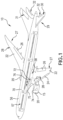
- FIG. 1 illustrates an example of a commercial aircraft (aircraft) 10 having a gas turbine engine (engine) 15, illustrated schematically.
- the engine 15 may be surrounded by (or otherwise carried in) a nacelle 20.
- the aircraft 10 includes a fuselage 56 with a cabin 57 therein (illustrated schematically).
- Two wings 22 are connected to the fuselage 56 though a wing-to-body fairing (fairing) 58.
- the two wings 22 can each include one or more slats 24 and one or more flaps 26.
- the aircraft may further include ailerons 27, spoilers 28, horizontal stabilizer trim tabs 29, horizontal stabilizer 30 and rudder 31, and vertical stabilizer 32 (the tail structure being collectively referred to as an and empennage) each of which may be typically referred to as "control surfaces" as they are movable under aircraft power systems.
- the aircraft 10 is equipped with an air management system (AMS) 70 illustrated schematically.
- the AMS 70 includes at least one Pressurization Air Conditioning arrangement 72.
- the arrangement 72 is located in the fairing 58 between the two wings 22 beneath the fuselage 56. Or course, this is not meant as limiting.
- Air supplied to an input 73, which may be an input conduit, of the arrangement 72 is bled from a compressor 74 (illustrated schematically) of the engine 15.
- the arrangement 72 may receive ram air from a ram air intake 75.
- the arrangement 72 includes a turbine 76 illustrated schematically in FIG. 1 .
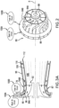
- the rotor 80 utilized in the turbine 76 is shown.
- the rotor 80 is a dual-scroll rotor.
- the rotor 80 has two sets of rotor blades generally referred to as 84.
- An inner shroud 86 separates a first set of rotor blades 84A from a second set of rotor blades 84B.
- the housing 87 and shroud 86 together form an inner turbine passage about the first set of rotor blades 84A and an outer turbine passage about the second set of rotor blades 84B.
- the rotor 80 is a unitary structure having a shaft through-hole 88 along a radial center R.
- the rotor 80 is configured to receive as working fluid bleed air 100A and fresh air 100B as discussed in greater detail with FIGS. 3A and 3B .
- FIGS. 3A and 3B show cross-sections of a turbine 76 connected to a diffuser 96 in two operational modes.
- the turbine 76 can include the rotor 80 surrounded by a turbine housing 87.
- the turbine 76, with the rotor 80 forms a centrifugal radial-inflow dual-scroll.
- the turbine housing 87 includes an exhaust 92 spanning the outputs of both sets of blades of the rotor 80.
- the exhaust 92 of the turbine 76 is shrouded by a diffuser 96.
- the diffuser 78 may be conical.
- the turbine 76 receives a first gas flow 100A bleed air from the engine 15.
- the first gas flow 100A is directed to the first set of rotor blades 84A.
- the turbine 76 also receives a second gas flow 100B from, for example, a fresh air circuit.
- the fresh air circuit may provide ram air through a ram air intake of the aircraft 10, but other sources or fresh air from outside the aircraft.
- the diffuser includes a diffuser inner diffuser passage 108 and an outer diffuser passage 112.
- the two passages are separated by an exhaust shroud 106 radially inward from an outer shell 107 of the diffuser 96.
- the exhaust shroud 106 is radially level with the inner shroud of the rotor 80 at the exhaust 92 of the turbine housing 87.
- the exhaust shroud 106 divides the diffuser 96 into the inner diffuser passage 108 and the outer diffuser passage 112.
- One or more support struts (struts) 116 may extend between the exhaust shroud 106 and the diffuser 96 as support.
- the exhaust shroud 106 may have a conical profile that increases away from the turbine 76. The increase in the conical profile may match that of the diffuser 96. Under such configuration each of the struts 116 may have a same size, for example in a radial direction, defining a height of the struts 116.
- the exhaust shroud 106 may be the same length as the diffuser 96.
- the exhaust shroud 106 may be the same material as the diffuser 96. In one embodiment the exhaust shroud 106 is manufactured as an integral part of the diffuser 96.
- the AMS 70 may operate in a plurality of modes depending on needs of the aircraft 10.
- the first mode of operation is illustrated in FIG. 3A .
- the turbine 76 may receive only the first gas flow 100A.
- the second mode of operation is illustrated in FIG. 3B .
- the turbine 76 may receive the first gas flow 100A and the second gas flow 100B.
- exhaust shroud 106 Without the exhaust shroud 106 if the diffuser 96, during the first mode of operation of the AMS 70, there is a sudden expansion of air leaving the turbine 76 at the exhaust 92 of the turbine 76. This expansion leads to operational inefficiencies, including diffuser stall.
- the exhaust shroud 106 prevents the sudden explanation at the exhaust 92 of the turbine 76.
- exhaust from the first set of rotor blades 84A is able to smoothly transition from the turbine 76 into the diffuser 96. This results in a more efficient utilization of the turbine 76 and thus a more efficient operation of the AMS 70. In turn, this results in more efficient use of bleed air from the engine 15, and therefore a more efficient use of the engine 15.
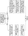
- a flowchart shows a method of directing flows through a turbine 76 of an air conditioning arrangement 72 which is part of an AMS 70 of an aircraft 10.
- the method includes determining whether the AMS 70 is operating in the first operational mode or the second operational mode.
- the first operational mode is a single flow operational mode. In the first operational mode the first gas flow 100A is directed to the turbine 76. In the second operational mode the first gas flow 100A and the second gas flow 100B are directed to the turbine 76.
- the method includes directing the first gas flow 100A to the first set of rotor blades 84A of the turbine 76. As illustrated in block 540, the method includes directing the first gas flow 100A within the turbine 76 by the inner shroud 86. As illustrated in block 550, the method includes exhausting the first gas flow 100A into the inner diffuser passage 108. As indicated the inner diffuser passage 108 is one of a plurality of diffuser passages including the inner diffuser passage and an outer diffuser passage is formed by the exhaust shroud 106 of the diffuser 96 extending from the inner shroud 86 of the turbine 76.
- the method includes directing the first gas flow 100A to the first set of rotor blades 84A and the second gas flow 100B to the second set of rotor blades 84B of the turbine 76.
- the method includes separating the first gas flow 100A and the second gas flow 100B within the turbine 76 by the inner shroud 86.
- the method includes exhausting the first gas flow 100A into the inner diffuser passage 108 and the second gas flow 100B into the outer diffuser passage 112.
Landscapes
- Engineering & Computer Science (AREA)
- Mechanical Engineering (AREA)
- General Engineering & Computer Science (AREA)
- Health & Medical Sciences (AREA)
- General Health & Medical Sciences (AREA)
- Pulmonology (AREA)
- Aviation & Aerospace Engineering (AREA)
- Chemical & Material Sciences (AREA)
- Combustion & Propulsion (AREA)
- Structures Of Non-Positive Displacement Pumps (AREA)
- Turbine Rotor Nozzle Sealing (AREA)
Abstract
Description
- The disclosure is related to a centrifugal turbines and more specifically to a diffuser for a dual passage radial turbine of an air management system, wherein the diffuser includes an exhaust shroud.
- An air management system (AMS) of an aircraft may include a pressurization air conditioning arrangement. The arrangement receives bleed air from a compressor of a gas turbine engine. The arrangement may include a turbine. The turbine may be a centrifugal turbine. Energy from the bleed air is removed by the turbine to drive the arrangement. From this, the AMS is able to condition the bleed air. The conditioned bleed air is directed to, for example, the aircraft cabin and aircraft electronics.
- Disclosed is a pressurization air conditioning arrangement, the arrangement comprising: a turbine including a housing and a rotor within the housing, wherein the rotor is a dual scroll and including an inner shroud separating a first set of rotor blades from a second set of rotor blades; a diffuser extending from an exhaust of the turbine; and an exhaust shroud within the diffuser, the exhaust shroud dividing the diffuser into an inner diffuser passage and an outer diffuser passage.
- In addition to one or more of the above disclosed aspects or as an alternate the exhaust shroud is radially level with the inner shroud of the rotor at an exhaust of a turbine housing.
- In addition to one or more of the above disclosed aspects or as an alternate the exhaust shroud has a conical profile.
- In addition to one or more of the above disclosed aspects or as an alternate the system includes one or more struts extending between the diffuser and the exhaust shroud.
- In addition to one or more of the above disclosed aspects or as an alternate each of the one or more struts has a same height in a radial direction.
- In addition to one or more of the above disclosed aspects or as an alternate the diffuser and the exhaust shroud are formed as a unitary structure.
- In addition to one or more of the above disclosed aspects or as an alternate: the first set of rotor blades is configured to receive a first gas flow; the second set of rotor blades is configured to receive a second gas flow; the first gas flow and the second gas flow are separated in the turbine by the inner shroud of the rotor; and the first gas flow and the second gas flow are separated in the diffuser by the exhaust shroud of the diffuser.
- In addition to one or more of the above disclosed aspects or as an alternate when the first set of rotor blades receives the first gas flow, the exhaust shroud prevents the first gas flow from expanding into the outer diffuser passage.
- Further disclosed is an air management system for an aircraft, comprising: a pressurization air conditioning arrangement, including an input to receive one or both bleed/fresh air and provide air to a cabin the arrangement including: a turbine; a rotor within the turbine, the rotor being a dual-scroll rotor and including an inner shroud separating a first set of rotor blades from a second set of rotor blades; a diffuser extending from an exhaust of the turbine; and an exhaust shroud within the diffuser, the exhaust shroud dividing the diffuser into an inner diffuser passage and an outer diffuser passage.
- In addition to one or more of the above disclosed aspects or as an alternate the first gas flow is bleed air from an engine and the second gas flow is ram air.
- Further disclosed is an aircraft comprising an air management system having one or more of the above disclosed features.
- Further disclosed is a method of directing flows through a turbine of an air management system for an aircraft, the method comprising: directing a first gas flow to a first set of rotor blades of the turbine and a second gas flow to a second set of rotor blades of the turbine; separating the first gas flow and the second gas flow within the turbine by an inner shroud; exhausting the first gas flow into an inner diffuser passage and the second gas flow into an outer diffuser passage formed by an exhaust shroud extending through a diffuser from the inner shroud of the rotor.
- In addition to one or more of the above disclosed aspects or as an alternate, in another mode of operation, the method consists of directing the first gas flow to the first set of rotor blades of the turbine; directing the first gas flow within the turbine by an inner shroud of a rotor; exhausting the first gas flow into the inner diffuser passage.
- The following descriptions should not be considered limiting in any way. With reference to the accompanying drawings, like elements are numbered alike:
-
FIG. 1 is a perspective view of an aircraft where the disclosed embodiments may be implemented; -
FIG. 2 is a perspective view of a rotor which can be utilized in an air management system according to disclosed embodiments; -
FIGS. 3A-3B show a turbine and diffuser configuration which can be utilized in an air management system according to disclosed embodiments; and -
FIG. 4 is a flowchart illustrating a method of directing flow utilizing an air management system according to disclosed embodiments. -
FIG. 1 illustrates an example of a commercial aircraft (aircraft) 10 having a gas turbine engine (engine) 15, illustrated schematically. Theengine 15 may be surrounded by (or otherwise carried in) anacelle 20. Theaircraft 10 includes afuselage 56 with acabin 57 therein (illustrated schematically). Twowings 22 are connected to thefuselage 56 though a wing-to-body fairing (fairing) 58. The twowings 22 can each include one ormore slats 24 and one ormore flaps 26. The aircraft may further includeailerons 27,spoilers 28, horizontalstabilizer trim tabs 29,horizontal stabilizer 30 andrudder 31, and vertical stabilizer 32 (the tail structure being collectively referred to as an and empennage) each of which may be typically referred to as "control surfaces" as they are movable under aircraft power systems. - The
aircraft 10 is equipped with an air management system (AMS) 70 illustrated schematically. The AMS 70 includes at least one PressurizationAir Conditioning arrangement 72. As illustrated, thearrangement 72 is located in thefairing 58 between the twowings 22 beneath thefuselage 56. Or course, this is not meant as limiting. Air supplied to aninput 73, which may be an input conduit, of thearrangement 72 is bled from a compressor 74 (illustrated schematically) of theengine 15. As further discussed below, thearrangement 72 may receive ram air from aram air intake 75. Thearrangement 72 includes aturbine 76 illustrated schematically inFIG. 1 . - Turning to
FIG. 2 , arotor 80 utilized in theturbine 76 is shown. Therotor 80 is a dual-scroll rotor. Therotor 80 has two sets of rotor blades generally referred to as 84. Aninner shroud 86 separates a first set ofrotor blades 84A from a second set ofrotor blades 84B. When in a housing 87 (FIG. 3A ), thehousing 87 andshroud 86 together form an inner turbine passage about the first set ofrotor blades 84A and an outer turbine passage about the second set ofrotor blades 84B. Therotor 80 is a unitary structure having a shaft through-hole 88 along a radial center R. Therotor 80 is configured to receive as working fluid bleedair 100A andfresh air 100B as discussed in greater detail withFIGS. 3A and3B . - Turning to
FIGS. 3A and3B , show cross-sections of aturbine 76 connected to adiffuser 96 in two operational modes. Theturbine 76 can include therotor 80 surrounded by aturbine housing 87. Theturbine 76, with therotor 80 forms a centrifugal radial-inflow dual-scroll. Theturbine housing 87 includes anexhaust 92 spanning the outputs of both sets of blades of therotor 80. Theexhaust 92 of theturbine 76 is shrouded by adiffuser 96. The diffuser 78 may be conical. - The
turbine 76 receives afirst gas flow 100A bleed air from theengine 15. Thefirst gas flow 100A is directed to the first set ofrotor blades 84A. Theturbine 76 also receives asecond gas flow 100B from, for example, a fresh air circuit. The fresh air circuit may provide ram air through a ram air intake of theaircraft 10, but other sources or fresh air from outside the aircraft. - The diffuser includes a diffuser
inner diffuser passage 108 and anouter diffuser passage 112. The two passages are separated by anexhaust shroud 106 radially inward from an outer shell 107 of thediffuser 96. Theexhaust shroud 106 is radially level with the inner shroud of therotor 80 at theexhaust 92 of theturbine housing 87. Theexhaust shroud 106 divides thediffuser 96 into theinner diffuser passage 108 and theouter diffuser passage 112. 106 - One or more support struts (struts) 116 may extend between the
exhaust shroud 106 and thediffuser 96 as support. Theexhaust shroud 106 may have a conical profile that increases away from theturbine 76. The increase in the conical profile may match that of thediffuser 96. Under such configuration each of thestruts 116 may have a same size, for example in a radial direction, defining a height of thestruts 116. Theexhaust shroud 106 may be the same length as thediffuser 96. Theexhaust shroud 106 may be the same material as thediffuser 96. In one embodiment theexhaust shroud 106 is manufactured as an integral part of thediffuser 96. - The
AMS 70 may operate in a plurality of modes depending on needs of theaircraft 10. The first mode of operation is illustrated inFIG. 3A . Under a first mode of operation, theturbine 76 may receive only thefirst gas flow 100A. The second mode of operation is illustrated inFIG. 3B . Under the second mode of operation, theturbine 76 may receive thefirst gas flow 100A and thesecond gas flow 100B. - Without the
exhaust shroud 106 if thediffuser 96, during the first mode of operation of theAMS 70, there is a sudden expansion of air leaving theturbine 76 at theexhaust 92 of theturbine 76. This expansion leads to operational inefficiencies, including diffuser stall. Theexhaust shroud 106 prevents the sudden explanation at theexhaust 92 of theturbine 76. As illustrated inFIG. 3B , exhaust from the first set ofrotor blades 84A is able to smoothly transition from theturbine 76 into thediffuser 96. This results in a more efficient utilization of theturbine 76 and thus a more efficient operation of theAMS 70. In turn, this results in more efficient use of bleed air from theengine 15, and therefore a more efficient use of theengine 15. - Turning to
FIG. 4 , a flowchart shows a method of directing flows through aturbine 76 of anair conditioning arrangement 72 which is part of anAMS 70 of anaircraft 10. As illustrated in block 510, the method includes determining whether theAMS 70 is operating in the first operational mode or the second operational mode. As indicated, the first operational mode is a single flow operational mode. In the first operational mode thefirst gas flow 100A is directed to theturbine 76. In the second operational mode thefirst gas flow 100A and thesecond gas flow 100B are directed to theturbine 76. - If the flow is the first operational mode (
Mode 1 at block 520) then as illustrated in block 530, the method includes directing thefirst gas flow 100A to the first set ofrotor blades 84A of theturbine 76. As illustrated in block 540, the method includes directing thefirst gas flow 100A within theturbine 76 by theinner shroud 86. As illustrated in block 550, the method includes exhausting thefirst gas flow 100A into theinner diffuser passage 108. As indicated theinner diffuser passage 108 is one of a plurality of diffuser passages including the inner diffuser passage and an outer diffuser passage is formed by theexhaust shroud 106 of thediffuser 96 extending from theinner shroud 86 of theturbine 76. - If the flow is the second operational mode (
Mode 2 at block 520) then as illustrated in block 560, the method includes directing thefirst gas flow 100A to the first set ofrotor blades 84A and thesecond gas flow 100B to the second set ofrotor blades 84B of theturbine 76. As illustrated in block 570, the method includes separating thefirst gas flow 100A and thesecond gas flow 100B within theturbine 76 by theinner shroud 86. As illustrated in block 580, the method includes exhausting thefirst gas flow 100A into theinner diffuser passage 108 and thesecond gas flow 100B into theouter diffuser passage 112. - The terminology used herein is for the purpose of describing particular embodiments only and is not intended to be limiting of the present disclosure. As used herein, the singular forms "a", "an" and "the" are intended to include the plural forms as well, unless the context clearly indicates otherwise. It will be further understood that the terms "comprises" and/or "comprising," when used in this specification, specify the presence of stated features, integers, steps, operations, elements, and/or components, but do not preclude the presence or addition of one or more other features, integers, steps, operations, element components, and/or groups thereof.
- Those of skill in the art will appreciate that various example embodiments are shown and described herein, each having certain features in the particular embodiments, but the present disclosure is not thus limited. Rather, the present disclosure can be modified to incorporate any number of variations, alterations, substitutions, combinations, sub-combinations, or equivalent arrangements not heretofore described, but which are commensurate with the scope of the present disclosure. Additionally, while various embodiments of the present disclosure have been described, it is to be understood that aspects of the present disclosure may include only some of the described embodiments. Accordingly, the present disclosure is not to be seen as limited by the foregoing description, but is only limited by the scope of the appended claims.
- The following clauses set out features of the invention which may not presently be claimed in this application, but which may form the basis for future amendment or a divisional application.
- 1. A pressurization air conditioning arrangement comprising:
- a turbine (76) including a housing and a rotor (80) within the housing (87), wherein the rotor is dual scroll and includes an inner shroud separating a first set of rotor blades from a second set of rotor blades;
- a diffuser (78) extending from an exhaust of the turbine; and
- an exhaust shroud within the diffuser, the exhaust shroud dividing the diffuser into an inner diffuser passage and an outer diffuser passage.
- 2. The arrangement of
clause 1, wherein the exhaust shroud is radially aligned with the inner shroud of the rotor at an exhaust of a turbine housing. - 3. The arrangement of
clause 2, wherein the exhaust shroud has a conical profile. - 4. The arrangement of any preceding clause, further comprising one or more struts extending between an outer shell of the diffuser and the exhaust shroud, optionally
wherein each of the one or more struts has a same radial dimension. - 5. The arrangement of any preceding clause, wherein the diffuser and the exhaust shroud are formed as a unitary structure.
- 6. The arrangement of any preceding clause, wherein:
- the first set of rotor blades is configured to receive a first gas flow;
- the second set of rotor blades is configured to receive a second gas flow;
- the first gas flow and the second gas flow are separated in the turbine by the inner shroud of the rotor; and
- the first gas flow and the second gas flow are separated in the diffuser by the exhaust shroud of the diffuser, and optionally
- wherein when the first set of rotor blades receives the first gas flow, the exhaust shroud prevents the first gas flow from expanding into the outer diffuser passage.
- 7. An air management system for an aircraft, comprising:
a pressurization air conditioning arrangement, including an input to receive one or both bleed air and fresh air and provide air to a cabin the arrangement including:- a turbine (76);
- a rotor (87) within the turbine, the rotor being a dual-scroll rotor and including an inner shroud separating a first set of rotor blades from a second set of rotor blades;
- a diffuser (78) extending from an exhaust of the turbine; and
- an exhaust shroud within the diffuser, the exhaust shroud dividing the diffuser into an inner diffuser passage and an outer diffuser passage.
- 8. The system of clause 7, wherein the exhaust shroud is radially level with the inner shroud of the rotor at a turbine housing exhaust.
- 9. The system of clause 7 or 8, wherein the exhaust shroud has a conical profile.
- 10. The system of any of clauses 7 to 9, comprising one or more struts extending between the diffuser and the exhaust shroud, and optionally
- wherein each of the one or more struts has a same height in a radial direction, optionally
- wherein the diffuser and the exhaust shroud are formed from a unitary structure.
- 11. The system of any of clauses 7 to 10, wherein:
- the first set of rotor blades is configured to receive a first gas flow;
- the second set of rotor blades is configured to receive a second gas flow;
- the first gas flow and the second gas flow are separated in the turbine by the inner shroud of the rotor; and
- the first gas flow and the second gas flow are separated in the diffuser by the exhaust shroud of the diffuser.
- 12. The system of clause 11, wherein when the first set of rotor blades receives the first gas flow, the exhaust shroud prevents the first gas flow from expanding into the outer diffuser passage, or
wherein the first gas flow is bleed air from an engine and the second gas flow is ram air. - 13. An aircraft comprising the air management system of any of clauses 7 to 12.
- 14. A method of directing flows through a turbine of an air management system for an aircraft, the method comprising:
- directing a first fluid flow to a first set of rotor blades of the turbine (76) and a second fluid flow to a second set of rotor blades of the turbine;
- separating the first fluid flow and the second fluid flow within the turbine by an inner shroud;
- exhausting the first fluid flow into an inner diffuser passage and the second fluid flow into an outer diffuser passage formed by an exhaust shroud extending through a diffuser from the inner shroud of the rotor.
- 15. The method of clause 14, wherein, in another mode of operation, the method consists of directing the first gas flow to the first set of rotor blades of the turbine;
- directing the first gas flow within the turbine by an inner shroud of a rotor;
- exhausting the first gas flow into the inner diffuser passage.
Claims (10)
- A pressurization air conditioning arrangement comprising:a turbine (76) including a housing and a rotor (80) within the housing (87), wherein the rotor is dual scroll and includes an inner shroud separating a first set of rotor blades from a second set of rotor blades;a diffuser (78) extending from an exhaust of the turbine; andan exhaust shroud within the diffuser, the exhaust shroud dividing the diffuser into an inner diffuser passage and an outer diffuser passage.
- The arrangement of claim 1, wherein the exhaust shroud is radially aligned with the inner shroud of the rotor at an exhaust of a turbine housing.
- The arrangement of claim 2, wherein the exhaust shroud has a conical profile.
- The arrangement of any preceding claim, further comprising one or more struts extending between an outer shell of the diffuser and the exhaust shroud, optionally
wherein each of the one or more struts has a same radial dimension. - The arrangement of any preceding claim, wherein the diffuser and the exhaust shroud are formed as a unitary structure.
- The arrangement of any preceding claim, wherein:the first set of rotor blades is configured to receive a first gas flow;the second set of rotor blades is configured to receive a second gas flow;the first gas flow and the second gas flow are separated in the turbine by the inner shroud of the rotor; andthe first gas flow and the second gas flow are separated in the diffuser by the exhaust shroud of the diffuser, and optionallywherein when the first set of rotor blades receives the first gas flow, the exhaust shroud prevents the first gas flow from expanding into the outer diffuser passage.
- An air management system for an aircraft, comprising:
the pressurization air conditioning arrangement of any preceding claim, the pressurization arrangement including an input to receive one or both bleed air and fresh air and provide air to a cabin - An aircraft comprising the air management system of claim 7.
- A method of directing flows through the turbine of the air management system of claim 7, the method comprising:directing a first fluid flow to a first set of rotor blades of the turbine (76) and a second fluid flow to a second set of rotor blades of the turbine;separating the first fluid flow and the second fluid flow within the turbine by an inner shroud;exhausting the first fluid flow into an inner diffuser passage and the second fluid flow into an outer diffuser passage formed by an exhaust shroud extending through a diffuser from the inner shroud of the rotor.
- The method of claim 9, wherein, in another mode of operation, the method consists of: directing the first gas flow to the first set of rotor blades of the turbine;directing the first gas flow within the turbine by an inner shroud of a rotor;exhausting the first gas flow into the inner diffuser passage.
Applications Claiming Priority (2)
| Application Number | Priority Date | Filing Date | Title |
|---|---|---|---|
| US16/562,975 US11371362B2 (en) | 2019-09-06 | 2019-09-06 | Diffuser with exhaust shroud |
| EP19211768.7A EP3789595B1 (en) | 2019-09-06 | 2019-11-27 | Pressurization air conditioning arrangement |
Related Parent Applications (1)
| Application Number | Title | Priority Date | Filing Date |
|---|---|---|---|
| EP19211768.7A Division EP3789595B1 (en) | 2019-09-06 | 2019-11-27 | Pressurization air conditioning arrangement |
Publications (2)
| Publication Number | Publication Date |
|---|---|
| EP4261387A2 true EP4261387A2 (en) | 2023-10-18 |
| EP4261387A3 EP4261387A3 (en) | 2024-01-10 |
Family
ID=68699302
Family Applications (2)
| Application Number | Title | Priority Date | Filing Date |
|---|---|---|---|
| EP19211768.7A Active EP3789595B1 (en) | 2019-09-06 | 2019-11-27 | Pressurization air conditioning arrangement |
| EP23195485.0A Pending EP4261387A3 (en) | 2019-09-06 | 2019-11-27 | Pressurization air conditioning arrangement |
Family Applications Before (1)
| Application Number | Title | Priority Date | Filing Date |
|---|---|---|---|
| EP19211768.7A Active EP3789595B1 (en) | 2019-09-06 | 2019-11-27 | Pressurization air conditioning arrangement |
Country Status (2)
| Country | Link |
|---|---|
| US (1) | US11371362B2 (en) |
| EP (2) | EP3789595B1 (en) |
Families Citing this family (1)
| Publication number | Priority date | Publication date | Assignee | Title |
|---|---|---|---|---|
| EP4728169A1 (en) * | 2023-06-13 | 2026-04-22 | Beehive Industries, LLC | Impeller |
Family Cites Families (8)
| Publication number | Priority date | Publication date | Assignee | Title |
|---|---|---|---|---|
| CH215484A (en) | 1939-11-17 | 1941-06-30 | Sulzer Ag | Gas turbine plant. |
| DE1032033B (en) | 1956-07-12 | 1958-06-12 | Plessey Co Ltd | Ram air turbine as a power source for auxiliary equipment in a gas turbine aircraft |
| US2999631A (en) | 1958-09-05 | 1961-09-12 | Gen Electric | Dual airfoil |
| JP4040556B2 (en) | 2003-09-04 | 2008-01-30 | 株式会社日立製作所 | Gas turbine equipment and cooling air supply method |
| JP4969500B2 (en) | 2008-03-28 | 2012-07-04 | 三菱重工業株式会社 | gas turbine |
| JP4958967B2 (en) | 2009-12-15 | 2012-06-20 | 川崎重工業株式会社 | Gas turbine engine with improved ventilation structure |
| JP5222384B2 (en) | 2011-09-09 | 2013-06-26 | 三菱重工業株式会社 | gas turbine |
| US8978351B2 (en) | 2011-10-21 | 2015-03-17 | United Technologies Corporation | Integrated thermal management system and environmental control system for a gas turbine engine |
-
2019
- 2019-09-06 US US16/562,975 patent/US11371362B2/en active Active
- 2019-11-27 EP EP19211768.7A patent/EP3789595B1/en active Active
- 2019-11-27 EP EP23195485.0A patent/EP4261387A3/en active Pending
Also Published As
| Publication number | Publication date |
|---|---|
| EP4261387A3 (en) | 2024-01-10 |
| US11371362B2 (en) | 2022-06-28 |
| US20210071536A1 (en) | 2021-03-11 |
| EP3789595A1 (en) | 2021-03-10 |
| EP3789595B1 (en) | 2023-09-06 |
Similar Documents
| Publication | Publication Date | Title |
|---|---|---|
| US10738706B2 (en) | Propulsion system for an aircraft | |
| US6438941B1 (en) | Bifurcated splitter for variable bleed flow | |
| EP3421369A1 (en) | Propulsion system for an aircraft | |
| EP2462332B1 (en) | Coannular ducted fan | |
| EP3421367A1 (en) | Propulsion system for an aircraft | |
| US20170159451A1 (en) | Turbine engine with an airfoil having a tip shelf outlet | |
| US10883515B2 (en) | Method and system for leading edge auxiliary vanes | |
| EP3199763A1 (en) | Blade and corresponding forming method | |
| US10920713B2 (en) | Compression cowl for jet engine exhaust | |
| EP3214270A1 (en) | Airfoil having impingement openings | |
| CN106246410B (en) | Aircraft and method for optimizing bleed air medium supplied to an aircraft environmental control system | |
| US20230220815A1 (en) | Three-stream gas turbine engine control | |
| CN112879166A (en) | Controlling a compressor of a turbine engine | |
| EP3181816A1 (en) | Airfoil for a gas turbine engine, corresponding forming method and component | |
| EP3208422A1 (en) | Airfoil having crossover holes | |
| EP2878796A1 (en) | Engine duct and aircraft engine | |
| US11208901B2 (en) | Trailing edge cooling for a turbine blade | |
| US20170121030A1 (en) | Turbofan engine and method of reducing air flow separation therein | |
| EP3196409A2 (en) | Turbine compressor vane | |
| EP3789595B1 (en) | Pressurization air conditioning arrangement | |
| US10697301B2 (en) | Turbine engine airfoil having a cooling circuit | |
| EP3611351A1 (en) | A turbine-tip clearance control system offtake | |
| US12577890B2 (en) | Oil tank for a turbomachine with negative-G-compatible cyclonic circulation | |
| CN108691654B (en) | System and method for back-up managed air system powered engine injector | |
| US12331652B2 (en) | Fan blade assembly with midspan shroud |
Legal Events
| Date | Code | Title | Description |
|---|---|---|---|
| PUAI | Public reference made under article 153(3) epc to a published international application that has entered the european phase |
Free format text: ORIGINAL CODE: 0009012 |
|
| STAA | Information on the status of an ep patent application or granted ep patent |
Free format text: STATUS: THE APPLICATION HAS BEEN PUBLISHED |
|
| AC | Divisional application: reference to earlier application |
Ref document number: 3789595 Country of ref document: EP Kind code of ref document: P |
|
| AK | Designated contracting states |
Kind code of ref document: A2 Designated state(s): AL AT BE BG CH CY CZ DE DK EE ES FI FR GB GR HR HU IE IS IT LI LT LU LV MC MK MT NL NO PL PT RO RS SE SI SK SM TR |
|
| REG | Reference to a national code |
Ref country code: DE Ref legal event code: R079 Free format text: PREVIOUS MAIN CLASS: F01D0005020000 Ipc: F02C0006080000 |
|
| PUAL | Search report despatched |
Free format text: ORIGINAL CODE: 0009013 |
|
| AK | Designated contracting states |
Kind code of ref document: A3 Designated state(s): AL AT BE BG CH CY CZ DE DK EE ES FI FR GB GR HR HU IE IS IT LI LT LU LV MC MK MT NL NO PL PT RO RS SE SI SK SM TR |
|
| RIC1 | Information provided on ipc code assigned before grant |
Ipc: F01D 5/02 20060101ALI20231204BHEP Ipc: F02C 6/08 20060101AFI20231204BHEP |
|
| STAA | Information on the status of an ep patent application or granted ep patent |
Free format text: STATUS: REQUEST FOR EXAMINATION WAS MADE |
|
| 17P | Request for examination filed |
Effective date: 20240710 |
|
| RBV | Designated contracting states (corrected) |
Designated state(s): AL AT BE BG CH CY CZ DE DK EE ES FI FR GB GR HR HU IE IS IT LI LT LU LV MC MK MT NL NO PL PT RO RS SE SI SK SM TR |
|
| GRAP | Despatch of communication of intention to grant a patent |
Free format text: ORIGINAL CODE: EPIDOSNIGR1 |
|
| STAA | Information on the status of an ep patent application or granted ep patent |
Free format text: STATUS: GRANT OF PATENT IS INTENDED |
|
| RIC1 | Information provided on ipc code assigned before grant |
Ipc: F02C 6/08 20060101AFI20260203BHEP Ipc: F01D 5/02 20060101ALI20260203BHEP |
|
| INTG | Intention to grant announced |
Effective date: 20260217 |