EP4261365A1 - Energy harvesting methods on door locks - Google Patents
Energy harvesting methods on door locks Download PDFInfo
- Publication number
- EP4261365A1 EP4261365A1 EP23164106.9A EP23164106A EP4261365A1 EP 4261365 A1 EP4261365 A1 EP 4261365A1 EP 23164106 A EP23164106 A EP 23164106A EP 4261365 A1 EP4261365 A1 EP 4261365A1
- Authority
- EP
- European Patent Office
- Prior art keywords
- thumb
- nanogenerator
- spindle
- deadbolt
- turn
- Prior art date
- Legal status (The legal status is an assumption and is not a legal conclusion. Google has not performed a legal analysis and makes no representation as to the accuracy of the status listed.)
- Pending
Links
- 238000000034 method Methods 0.000 title claims abstract description 22
- 238000003306 harvesting Methods 0.000 title description 3
- 230000005611 electricity Effects 0.000 claims abstract description 22
- 238000004146 energy storage Methods 0.000 claims abstract description 13
- 238000004891 communication Methods 0.000 description 10
- 239000003990 capacitor Substances 0.000 description 8
- 238000010248 power generation Methods 0.000 description 8
- 238000010586 diagram Methods 0.000 description 3
- 230000008569 process Effects 0.000 description 3
- HBBGRARXTFLTSG-UHFFFAOYSA-N Lithium ion Chemical compound [Li+] HBBGRARXTFLTSG-UHFFFAOYSA-N 0.000 description 2
- 230000006870 function Effects 0.000 description 2
- 229910001416 lithium ion Inorganic materials 0.000 description 2
- 239000000463 material Substances 0.000 description 2
- 230000002000 scavenging effect Effects 0.000 description 2
- 239000000126 substance Substances 0.000 description 2
- 230000008901 benefit Effects 0.000 description 1
- 230000005540 biological transmission Effects 0.000 description 1
- 230000001413 cellular effect Effects 0.000 description 1
- 239000003985 ceramic capacitor Substances 0.000 description 1
- 230000000694 effects Effects 0.000 description 1
- 238000005259 measurement Methods 0.000 description 1
- 239000010445 mica Substances 0.000 description 1
- 229910052618 mica group Inorganic materials 0.000 description 1
- 238000012986 modification Methods 0.000 description 1
- 230000004048 modification Effects 0.000 description 1
- 238000012545 processing Methods 0.000 description 1
- 230000004044 response Effects 0.000 description 1
- 239000007787 solid Substances 0.000 description 1
Images


Classifications
-
- H—ELECTRICITY
- H02—GENERATION; CONVERSION OR DISTRIBUTION OF ELECTRIC POWER
- H02N—ELECTRIC MACHINES NOT OTHERWISE PROVIDED FOR
- H02N2/00—Electric machines in general using piezoelectric effect, electrostriction or magnetostriction
- H02N2/18—Electric machines in general using piezoelectric effect, electrostriction or magnetostriction producing electrical output from mechanical input, e.g. generators
-
- E—FIXED CONSTRUCTIONS
- E05—LOCKS; KEYS; WINDOW OR DOOR FITTINGS; SAFES
- E05B—LOCKS; ACCESSORIES THEREFOR; HANDCUFFS
- E05B15/00—Other details of locks; Parts for engagement by bolts of fastening devices
- E05B15/0033—Spindles for handles, e.g. square spindles
-
- E—FIXED CONSTRUCTIONS
- E05—LOCKS; KEYS; WINDOW OR DOOR FITTINGS; SAFES
- E05B—LOCKS; ACCESSORIES THEREFOR; HANDCUFFS
- E05B15/00—Other details of locks; Parts for engagement by bolts of fastening devices
- E05B15/02—Striking-plates; Keepers; Bolt staples; Escutcheons
-
- E—FIXED CONSTRUCTIONS
- E05—LOCKS; KEYS; WINDOW OR DOOR FITTINGS; SAFES
- E05B—LOCKS; ACCESSORIES THEREFOR; HANDCUFFS
- E05B47/00—Operating or controlling locks or other fastening devices by electric or magnetic means
- E05B47/0001—Operating or controlling locks or other fastening devices by electric or magnetic means with electric actuators; Constructional features thereof
- E05B47/0012—Operating or controlling locks or other fastening devices by electric or magnetic means with electric actuators; Constructional features thereof with rotary electromotors
-
- E—FIXED CONSTRUCTIONS
- E05—LOCKS; KEYS; WINDOW OR DOOR FITTINGS; SAFES
- E05B—LOCKS; ACCESSORIES THEREFOR; HANDCUFFS
- E05B59/00—Locks with latches separate from the lock-bolts or with a plurality of latches or lock-bolts
-
- E—FIXED CONSTRUCTIONS
- E05—LOCKS; KEYS; WINDOW OR DOOR FITTINGS; SAFES
- E05B—LOCKS; ACCESSORIES THEREFOR; HANDCUFFS
- E05B47/00—Operating or controlling locks or other fastening devices by electric or magnetic means
- E05B2047/0048—Circuits, feeding, monitoring
- E05B2047/0057—Feeding
- E05B2047/0062—Feeding by generator
-
- E—FIXED CONSTRUCTIONS
- E05—LOCKS; KEYS; WINDOW OR DOOR FITTINGS; SAFES
- E05B—LOCKS; ACCESSORIES THEREFOR; HANDCUFFS
- E05B47/00—Operating or controlling locks or other fastening devices by electric or magnetic means
- E05B2047/0048—Circuits, feeding, monitoring
- E05B2047/0065—Saving energy
Definitions
- the embodiments herein generally relate to door locks and more specifically, to a method and apparatus to using energy generation devices in door locks.
- a method of powering a door lock including a deadbolt and a thumb-turn lever mechanically connected to the deadbolt through one or more mechanical linkages including: converting mechanical energy of the deadbolt being moved to electricity using a nanogenerator; and providing the electricity to at least one of an energy storage device of the door lock or a controller of the door lock, wherein the nanogenerator is located on at least one of the thumb-turn lever, the deadbolt, or the one or more mechanical linkages.
- the nanogenerator may be a piezoelectric nanogenerator.
- the nanogenerator may be a triboelectric nanogenerator.
- the nanogenerator may be located on the thumb-turn lever.
- the nanogenerator may be located on a spindle receiver blind orifice of the thumb-turn lever.
- the nanogenerator may be located on the deadbolt.
- the one or more mechanical linkages may include a spindle receiver configured to translate the deadbolt as the spindle receiver rotates, wherein the nanogenerator may be located on the spindle receiver.
- the one or more mechanical linkages may include a thumb-turn rosette connecting the thumb-turn lever to a spindle receiver configured to translate the deadbolt as the spindle receiver rotates, wherein the nanogenerator may be located on the thumb-turn rosette.
- the thumb-turn rosette may include a first spindle located on a first side, the thumb-turn lever being configured to receive the first spindle, wherein the nanogenerator may be located on the first spindle.
- the thumb-turn rosette may include a second spindle located on a second side, the spindle receiver being configured to receive the second spindle, wherein the nanogenerator may be located on the second spindle.
- a door lock including: a deadbolt; a thumb-turn lever mechanically connected to the deadbolt through one or more mechanical linkages; and a nanogenerator configured to convert mechanical energy of the deadbolt being moved to electricity, wherein the nanogenerator is located on at least one of the thumb-turn lever, the deadbolt, or the one or more mechanical linkages.
- the nanogenerator may be a piezoelectric nanogenerator.
- the nanogenerator may be a triboelectric nanogenerator.
- the nanogenerator may be located on the thumb-turn lever.
- the nanogenerator may be located on a spindle receiver blind orifice of the thumb-turn lever.
- the nanogenerator may be located on the deadbolt.
- the one or more mechanical linkages may include a spindle receiver configured to translate the deadbolt as the spindle receiver rotates, wherein the nanogenerator may be located on the spindle receiver.
- the one or more mechanical linkages may include a thumb-turn rosette connecting the thumb-turn lever to a spindle receiver configured to translate the deadbolt as the spindle receiver rotates, wherein the nanogenerator may be located on the thumb-turn rosette.
- the thumb-turn rosette may include a first spindle located on a first side, the thumb-turn lever being configured to receive the first spindle, wherein the nanogenerator may be located on the first spindle.
- the thumb-turn rosette may include a second spindle located on a second side, the spindle receiver being configured to receive the second spindle, wherein the nanogenerator may be located on the second spindle.
- inventions of the present invention include generating electricity from mechanical energy of a deadbolt using nanogenerators located on at least one of the thumb-turn lever, the deadbolt, or the one or more mechanical linkages connecting the thumb-turn lever to the deadbolt.
- Embodiments disclosed herein relate to an apparatus and method for energy harvesting on door locks.
- Door locks are typically disconnected from power sources and require frequent battery changes to maintain operation.
- the embodiments disclosed herein seek to charge an energy storage device by harvest mechanical energy on door locks by placing nanogenerators on at least one of a deadbolt, a thumb-turn lever, or mechanical linkages connecting the thumb-turn lever to the deadbolt.
- the energy storage devices may be based on Lithium-Ion Batteries and supercapacitors.
- the energy storage device may be charge by a power generation device, which can collect and convert mechanical energy into electric energy in the surrounding environment.
- the energy storage device can store the scavenged energy as chemical energy.
- Energy scavenging function of the devices generation device may be realized by piezoelectric nanogenerators or triboelectric nanogenerators. This generates small amount of energy which will be useful to power lock's LEDs, motor, and buzzer. Nanogenerators convert kinematic energy to electrical energy when we apply pressure on those materials
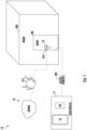
- FIG. 1 is schematic view of a door lock system 10, according to an embodiment of the present invention. It should be appreciated that, although particular systems are separately defined in the schematic block diagrams, each or any of the systems may be otherwise combined or separated via hardware and/or software.
- the door lock system 10 includes a door lock 16 operably connected to a door 202 of a room 208.
- the door lock 16 is configured to control access through the door 202 to the room 208.
- the door lock 16 includes a deadbolt 410 configured to be engaged and disengaged to lock and unlock the door 202, respectively.
- the deadbolt 410 may be engaged and disengaged from inside of the room 208.
- the user device 11 belonging to a person may be granted access to one or more door locks 16 (e.g., the door lock on a hotel room assigned to the person).
- door locks 16 e.g., the door lock on a hotel room assigned to the person.
- a person checks into the hotel room their user device 11 will be granted access to a room 208.
- There may be one or more user devices 11 assigned to a room 208 e.g., a husband and a wife), thus embodiments disclosed herein may apply to multiple user devices 11 per room 208.
- a person may utilize their user device 11 to unlock and/or lock the door lock 16 operably connected to their assigned room 208 through an access request 304.
- the user device 11 may store credentials to unlock and/or lock the door lock 16.
- Some credentials may be used for multiple door locks 16 if there are multiple door locks 16 for a single assigned room 208 or the person is assigned access to multiple rooms 208.
- a door lock 16 operably connected to a person's hotel room and a door lock 16 operably connected to a hotel pool may respond to the same credential.
- Other credentials may be specific to a single door lock 16.
- the user device 11 may be a physical key card 92 and/or a mobile device 12.
- the user device 11 may transmit an access request 304 to the door lock 16 by short-range radio transmission when the user device 11 is placed proximate the door lock 16 or by the user device 11 being inserted into the door lock 16 for the door lock to read the user device (e.g., a magnetic strip on an encoded card 92).
- the physical key card 92 is capable of being encoded with card data, such as, for example, a magnetic strip or RFID chip.
- the card data may include credentials to grant access to a specific door lock 16. For example, for a period of stay for the user device 11 may be granted access to a specific door lock 16.
- the mobile device 12 is a wireless capable handheld device such as a smartphone that is operable to communicate with the server 14 and the door locks 16.
- the server 14 may provide credentials and other data to the door lock 16, such as firmware or software updates to be communicated to one or more of the door locks 16.
- the server 14 is depicted herein as a single device, it should be appreciated that the server 14 may alternatively be embodied as a multiplicity of systems, from which the mobile device 12 receives credentials and other data.
- Each door lock 16 may be a wireless-capable, restricted-access, or restricted-use device such as wireless locks, door lock readers for building entry, and other restricted-use machines.
- the user device 11 submits credentials to the door locks 16, thereby selectively permitting a user to access or activate functions of the door locks 16.
- a user may, for example, submit a credential to an electromechanical lock to unlock it, and thereby gain access to a room 208.
- the door lock 16 may be wirelessly connected to the wireless access protocol device 212 and communicate wirelessly to the mobile device 12. In a non-limiting embodiment, even if the door lock 16 is wirelessly capable, communication between the mobile device 12 and the door lock 16 may occur through the server 14. For example, the door lock 16 may communicate wirelessly through the wireless access protocol device 212 to the server 14 and then the server 14 may relay the communication wirelessly to the mobile device 12. In a further example, the mobile device 12 may communicate wirelessly to the server 14 and the server 14 may communicate wirelessly through the wireless access protocol device 212 to the door lock 16. The communication between the server 14 and the mobile device 12 may occur through the wireless access protocol device 212 or another wireless network such as, for example, a cellular network.
- the communication may occur between the door lock 16 and the mobile device 12 via short range wireless communication, such as for example Wi-Fi, Bluetooth, zigbee, infrared, or any other short-range wireless communication method known to one of skill in the art.
- the short-range wireless communication is Bluetooth.
- the mobile device 12 may have to be within a selected range of the door lock 16 in order to utilize short-range wireless communication.
- FIG. 2 shows a block diagram of an example electronic lock system 20 that includes the door lock 16, the mobile device 12, and the server 14.
- the door lock 16 generally includes a lock actuator 22, a lock controller 24, a lock antenna 26, a lock transceiver 28, a lock processor 30, a lock memory 32, a lock power supply 34, a lock card reader 90 and a credential module 36.
- the door lock 16 may have essentially two readers, one reader 90 to read a physical key card 92 and the credential module 36 to communicate with the mobile device 12 via the lock processor 30 and the transceiver 28 and antenna 26.
- the present invention focuses primarily on credentials for door lock, it should be appreciated that other systems wherein credentials are transmitted from a mobile device to a door lock so as to identify the user to an online system or validate user access rights or permissions in an offline system will benefit herefrom.
- Such systems include hotel door lock systems.
- the lock controller 24 Upon receiving and authenticating an appropriate credential from the mobile device 12 using the credential module 36, or after receiving card data from lock card reader 90, the lock controller 24 commands the lock actuator 22 to lock or unlock a mechanical or electronic lock.
- the lock controller 24 and the lock actuator 22 may be parts of a single electronic or electromechanical lock unit, or may be components sold or installed separately.
- the lock transceiver 28 is capable of transmitting and receiving data to and from at least the mobile device 12.
- the lock transceiver 28 may, for instance, be a near field communication (NFC), Bluetooth, infrared, zigbee, or Wi-Fi transceiver, or another appropriate wireless transceiver.
- the lock antenna 26 is any antenna appropriate to the lock transceiver 28.
- the lock processor 30 and lock memory 32 are, respectively, data processing, and storage devices.
- the lock processor 30 may, for instance, be a microprocessor that can process instructions to validate credentials and determine the access rights contained in the credentials or to pass messages from a transceiver to a credential module 36 and to receive a response indication back from the credential module 36.
- the lock memory 32 may be RAM, EEPROM, or other storage medium where the lock processor 30 can read and write data including but not limited to lock configuration options.
- the lock power supply 34 is a power source such as an energy storage device 510 that powers the lock controller 24.
- the lock power supply includes an energy storage device 510 configured to store electricity and a power generation device 610 configured to generate electricity.
- the energy storage device 510 may include a rechargeable battery system 512, a super capacitor 514, and/or any other electricity storage system known to one of skill in the art.
- the rechargeable battery system 512 may comprise, chemical batteries, lithium-ion batteries, solid state batteries, flow batteries, or any other type of battery known to one of skill in the art.
- the rechargeable battery system 512 may employ multiple batteries organized into battery banks.
- the super capacitor 514 may be an electrolytic capacitor, a mica capacitor, a paper capacitor a film capacitor, a non-polarized capacitor, a ceramic capacitor, or any type of capacitor known to one of skill in the art.
- the lock power supply 34 may include one or more power generation devices 610.
- the power generation devices 610 may be energy scavenging devices configured to generate energy through various movements of the deadbolt 410, such as engaging and disengaging the deadbolt 410.
- the power generation device 610 may include a mechanical linkage generator 612 and/or a deadbolt generator 614, discussed further herein.
- the one or more power generation devices 610 are configured to generate electricity and provide the electricity to the energy storage device 510 and/or directly to the lock controller 24.
- the lock 16 may rely on the energy storage device 510 to power the initial opening and then after a certain number of open operations, the lock 16 may use energy generated by the power generation device 610.
- FIG. 2 shows the lock antenna 26 and the transceiver 28 connected to the processor 30, this is not to limit other embodiments that may have additional antenna 26 and transceiver 28 connected to the credential module 36 directly.
- the credential module 36 may contain a transceiver 28 and antenna 26 as part of the credential module. Or the credential module 36 may have a transceiver 28 and antenna 26 separately from the processor 30 which also has a separate transceiver 28 and antenna 26 of the same type or different.
- the processor 30 may route communication received via transceiver 28 to the credential module 36.
- the credential module may communicate directly to the mobile device 12 through the transceiver 28.
- the mobile device 12 generally includes a key antenna 40, a key transceiver 42, a key processor 44, a key memory 46, a GPS receiver 48, an input device 50, an output device 52, a key power supply 54, and a Microelectromechanical system (MEMS) 57.
- the key transceiver 42 is a transceiver of a type corresponding to the lock transceiver 28, and the key antenna 40 is a corresponding antenna.
- the key transceiver 42 and the key antenna 40 may also be used to communicate with the server 14.
- one or more separate transceivers and antennas may be included to communicate with server 14.
- the key memory 46 is of a type to store a plurality of credentials locally on the mobile device 12.
- the mobile device 12 may also include a mobile device application 80. Embodiments disclosed herein, may operate through the mobile device application 80 installed on the mobile device 12.
- the mobile device 12 may also include a microphone 58 configured to receive audible commands from a person.
- the MEMS sensor 57 may be a sensor such as, for example, an accelerometer, a gyroscope, or a similar sensor known to one of skill in the art.
- FIG. 3 a schematic illustration of the door lock 16 is illustrated, according to an embodiment of the present invention.
- the door lock 16 includes a thumb-turn lever 402 configured to engage and disengage the deadbolt 410.
- An individual may rotate the thumb-turn lever 402 in a first rotational direction D1 to engage the deadbolt 410 and a second rotational direction D2 to disengage the deadbolt 410.
- the deadbolt 410 is configured to be inserted into an orifice 252 of a strike plate 250 when the thumb-turn lever 402 is rotated to engage the deadbolt 410.
- the deadbolt 410 being located within the orifice 252 of the strike plate 250 secures the door 202 in a locked position.
- the strike plate 250 is located in a wall 254 that surrounds the door 202.
- the deadbolt 410 is configured to be removed from the orifice 252 of the strike plate 250 when the thumb-turn lever 402 is rotated to disengage the deadbolt 410.
- the deadbolt 410 being removed from the orifice 252 of the strike plate 250 unlocks the door 202.
- the deadbolt 410 may slide up against the strike plate 250 creating friction and/or pressure between the deadbolt 410 and the strike plate 250.
- the deadbolt generator 614 may be located on an outer surface 412 of the deadbolt 410, such that as the deadbolt 410 moves into and out of the orifice 252 of the strike plate 250, the deadbolt generator 614 may slide up against the strike plate 250 creating friction and/or pressure between the deadbolt generator 614 and strike plate 250.
- the deadbolt generator 614 may be composed of a plurality of nanogenerators 634 configured to generate electricity from the friction and/or pressure between the deadbolt generator 614 and strike plate 250.
- the nanogenerators 634 may include, but are not limited to, piezoelectric nanogenerators or triboelectric nanogenerators.
- the nanogenerators 634 are configured to convert the mechanical energy of the deadbolt 410 sliding in and out of the strike plate 250 into electricity.
- FIGS. 4 and 5 a schematic illustration of the door lock 16 is illustrated, according to an embodiment of the present invention.
- the door lock 16 includes a thumb-turn lever 402 configured to engage and disengage the deadbolt 410.
- the thumb-turn lever 402 is mechanically connected to the deadbolt 410 through a series of mechanical linkages, such that, as the individual rotates the thumb-turn lever 402 in a first rotational direction D 1 the deadbolt 410 engages and as the individual rotates the thumb-turn lever 402 in a second rotational direction D2 the deadbolt 410 disengages.
- a power generation device 610 may be located on one or more of the mechanical linkages mechanically connecting the thumb-turn lever 402 to the deadbolt 410 and/or on the thumb-turn lever 402 itself
- the series of mechanical linkages may include a thumb-turn rosette 420.
- the thumb-turn rosette 420 mechanically connects the thumb-turn lever 402 to a spindle receiver 406.
- the spindle receiver 406 is mechanically connected to the deadbolt 410 and the deadbolt 410 is configured to translate to engage and disengage as the spindle receiver 406 is rotated.
- the thumb-turn rosette 420 includes a first side 422 and a second side 424 located opposite the first side 422.
- the thumb-turn rosette 420 includes a first spindle 426 extending away from the first side 422 and a second spindle 428 extending away from the second side 424.
- the thumb-turn lever 402 includes a spindle receiver blind orifice 404 configured to receive the first spindle 426.
- the spindle receiver blind orifice 404 may also be configured to interlock with the first spindle 426.
- the second spindle 428 is rotationally linked to the first spindle 426 such that when the first spindle 426 is rotated that second spindle 428 also rotates.
- the spindle receiver 406 is configured to receive the second spindle 428.
- the spindle receiver 406 may be configured to interlock with the second spindle 428.
- the spindle receiver 406 is configured to be rotated by the second spindle 428.
- the mechanical linkage generator 612 may be located on the thumb-turn rosette 420, the first spindle 426, the second spindle 428, the receiver blind orifice 404, and/or the spindle receiver 406, such that as the thumb-turn lever 402 is rotated to engage or disengage the deadbolt 410, the friction and pressure experienced by the mechanical linkages between the thumb-turn lever 402 and the deadbolt 410 turned into electricity.
- the friction and pressure experienced by the mechanical linkages between the thumb-turn lever 402 and the deadbolt 410 may be friction and pressure with other mechanical linkages between the thumb-turn lever 402 and the deadbolt 410.
- the friction and pressure experienced by the mechanical linkages between the thumb-turn lever 402 and the deadbolt 410 may be friction and pressure with other components surrounding the mechanical linkages between the thumb-turn lever 402 and the deadbolt 410.
- the mechanical linkages between the thumb-turn lever 402 and the deadbolt 410 may include, but are not limited to the thumb-turn rosette 420, the first spindle 426, the second spindle 428, the receiver blind orifice 404, and/or the spindle receiver 406.
- the mechanical linkage generator 612 may be located on dead bolt sliding surface 440 located on the first side 422 of the thumb-turn rosette 420.
- the thumb-turn slide surface 440 is located beneath or opposite the thumb-turn lever 402, such that when the thumb-turn level 402 is rotated, the thumb-turn level 402 slides up against this thumb-turn slide surface 440 where the mechanical linkage generator 612 is located to generate electricity from the friction and/or pressure, as aforementioned.
- the mechanical linkage generator 612 may be composed of a plurality of nanogenerators 634 configured to generate electricity from the friction and/or pressure, as aforementioned.
- the nanogenerators 634 may include, but are not limited to, piezoelectric nanogenerators or triboelectric nanogenerators.
- the nanogenerators 634 are configured to convert the mechanical energy of the movement of the mechanical linkages into electricity.
- FIG. 6 within continued references to FIGS. 1-3 , a flow diagram illustrating a method 800 of powering a door lock 16 comprising a deadbolt 410 and a thumb-turn lever 402 mechanically connected to the deadbolt 410 through one or more mechanical linkages is illustrated, in accordance with an embodiment of the present invention.
- the nanogenerator 634 is a piezoelectric nanogenerator 634. In another embodiment, the nanogenerator 634 is a triboelectric nanogenerator 634.
- electricity is provided to at least one of an energy storage device 510 of the door lock 16 or a controller 24 of the door lock 16.
- the nanogenerator 634 is located on at least one of the thumb-turn lever 402, the deadbolt 410, or the one or more mechanical linkages.
- the nanogenerator 634 may be located on the thumb-turn lever 402.
- the nanogenerator 634 may be located on a spindle receiver blind orifice 404 of the thumb-turn lever 402.
- the nanogenerator 634 may be located on the deadbolt 410.
- the one or more mechanical linkages may include a spindle receiver 406 configured to translate the deadbolt 410 as the spindle receiver 406 rotates and the nanogenerator 634 is located on the spindle receiver 406.
- the one or more mechanical linkages may include a thumb-turn rosette 420 connecting the thumb-turn lever 402 to a spindle receiver configured to translate the deadbolt 410 as the spindle receiver 406 rotates and the nanogenerator 634 is located on the thumb-turn rosette 420.
- the thumb-turn rosette 420 may include a first spindle located on a first side 422.
- the thumb-turn lever 402 being configured to receive the first spindle 426 and the nanogenerator 634 may be located on the first spindle 426.
- the thumb-turn rosette 420 may include a second spindle 428 located on a second side 424.
- the spindle receiver 406 being configured to receive the second spindle 428 and the nanogenerator 634 may be located on the second spindle 428.
Landscapes
- Lock And Its Accessories (AREA)
Abstract
Description
- The embodiments herein generally relate to door locks and more specifically, to a method and apparatus to using energy generation devices in door locks.
- Door locks are typically disconnected from power sources and require frequent battery changes to maintain operation. A solution that requires less battery changes are greatly desired.
- According to a first aspect of the invention, a method of powering a door lock including a deadbolt and a thumb-turn lever mechanically connected to the deadbolt through one or more mechanical linkages is provided. The method including: converting mechanical energy of the deadbolt being moved to electricity using a nanogenerator; and providing the electricity to at least one of an energy storage device of the door lock or a controller of the door lock, wherein the nanogenerator is located on at least one of the thumb-turn lever, the deadbolt, or the one or more mechanical linkages.
- The nanogenerator may be a piezoelectric nanogenerator.
- The nanogenerator may be a triboelectric nanogenerator.
- The nanogenerator may be located on the thumb-turn lever.
- The nanogenerator may be located on a spindle receiver blind orifice of the thumb-turn lever.
- The nanogenerator may be located on the deadbolt.
- The one or more mechanical linkages may include a spindle receiver configured to translate the deadbolt as the spindle receiver rotates, wherein the nanogenerator may be located on the spindle receiver.
- The one or more mechanical linkages may include a thumb-turn rosette connecting the thumb-turn lever to a spindle receiver configured to translate the deadbolt as the spindle receiver rotates, wherein the nanogenerator may be located on the thumb-turn rosette.
- The thumb-turn rosette may include a first spindle located on a first side, the thumb-turn lever being configured to receive the first spindle, wherein the nanogenerator may be located on the first spindle.
- The thumb-turn rosette may include a second spindle located on a second side, the spindle receiver being configured to receive the second spindle, wherein the nanogenerator may be located on the second spindle.
- According to a second aspect of the invention, a door lock is provided. The door lock including: a deadbolt; a thumb-turn lever mechanically connected to the deadbolt through one or more mechanical linkages; and a nanogenerator configured to convert mechanical energy of the deadbolt being moved to electricity, wherein the nanogenerator is located on at least one of the thumb-turn lever, the deadbolt, or the one or more mechanical linkages.
- The nanogenerator may be a piezoelectric nanogenerator.
- The nanogenerator may be a triboelectric nanogenerator.
- The nanogenerator may be located on the thumb-turn lever.
- The nanogenerator may be located on a spindle receiver blind orifice of the thumb-turn lever.
- The nanogenerator may be located on the deadbolt.
- The one or more mechanical linkages may include a spindle receiver configured to translate the deadbolt as the spindle receiver rotates, wherein the nanogenerator may be located on the spindle receiver.
- The one or more mechanical linkages may include a thumb-turn rosette connecting the thumb-turn lever to a spindle receiver configured to translate the deadbolt as the spindle receiver rotates, wherein the nanogenerator may be located on the thumb-turn rosette.
- The thumb-turn rosette may include a first spindle located on a first side, the thumb-turn lever being configured to receive the first spindle, wherein the nanogenerator may be located on the first spindle.
- The thumb-turn rosette may include a second spindle located on a second side, the spindle receiver being configured to receive the second spindle, wherein the nanogenerator may be located on the second spindle.
- Technical effects of embodiments of the present invention include generating electricity from mechanical energy of a deadbolt using nanogenerators located on at least one of the thumb-turn lever, the deadbolt, or the one or more mechanical linkages connecting the thumb-turn lever to the deadbolt.
- The foregoing features and elements may be combined in various combinations without exclusivity, unless expressly indicated otherwise. These features and elements as well as the operation thereof will become more apparent in light of the following description and the accompanying drawings. It should be understood, however, that the following description and drawings are intended to be illustrative and explanatory in nature and non-limiting.
- The following descriptions should not be considered limiting in any way. With reference to the accompanying drawings, like elements are numbered alike:
-
FIG. 1 is a schematic illustration of an exemplary door lock system; -
FIG. 2 is a schematic view of an exemplary door lock, mobile device, and server; -
FIG. 3 illustrates a view of an exemplary dead bolt generator for the door lock; -
FIG. 4 illustrates a view of an exemplary mechanical linkage generator; -
FIG. 5 illustrates a view of an exemplary mechanical linkage generator; and -
FIG. 6 is a flow process illustrating an exemplary method of powering a door lock comprising a deadbolt and a thumb-turn lever mechanically connected to the deadbolt through one or more mechanical linkages. - A detailed description of one or more embodiments of the disclosed invention and method are presented herein by way of exemplification and not limitation with reference to the Figures.
- Embodiments disclosed herein relate to an apparatus and method for energy harvesting on door locks. Door locks are typically disconnected from power sources and require frequent battery changes to maintain operation. The embodiments disclosed herein seek to charge an energy storage device by harvest mechanical energy on door locks by placing nanogenerators on at least one of a deadbolt, a thumb-turn lever, or mechanical linkages connecting the thumb-turn lever to the deadbolt.
- The energy storage devices may be based on Lithium-Ion Batteries and supercapacitors. The energy storage device may be charge by a power generation device, which can collect and convert mechanical energy into electric energy in the surrounding environment. The energy storage device can store the scavenged energy as chemical energy. Energy scavenging function of the devices generation device may be realized by piezoelectric nanogenerators or triboelectric nanogenerators. This generates small amount of energy which will be useful to power lock's LEDs, motor, and buzzer. Nanogenerators convert kinematic energy to electrical energy when we apply pressure on those materials
-
FIG. 1 is schematic view of adoor lock system 10, according to an embodiment of the present invention. It should be appreciated that, although particular systems are separately defined in the schematic block diagrams, each or any of the systems may be otherwise combined or separated via hardware and/or software. Thedoor lock system 10 includes adoor lock 16 operably connected to adoor 202 of aroom 208. Thedoor lock 16 is configured to control access through thedoor 202 to theroom 208. Thedoor lock 16 includes adeadbolt 410 configured to be engaged and disengaged to lock and unlock thedoor 202, respectively. Thedeadbolt 410 may be engaged and disengaged from inside of theroom 208. - For a selected period of stay (e.g., period of time for a person staying at a hotel) the
user device 11 belonging to a person may be granted access to one or more door locks 16 (e.g., the door lock on a hotel room assigned to the person). For example, when a person checks into the hotel room theiruser device 11 will be granted access to aroom 208. There may be one ormore user devices 11 assigned to a room 208 (e.g., a husband and a wife), thus embodiments disclosed herein may apply tomultiple user devices 11 perroom 208. A person may utilize theiruser device 11 to unlock and/or lock thedoor lock 16 operably connected to their assignedroom 208 through anaccess request 304. Theuser device 11 may store credentials to unlock and/or lock thedoor lock 16. Some credentials may be used formultiple door locks 16 if there aremultiple door locks 16 for a single assignedroom 208 or the person is assigned access tomultiple rooms 208. For example, adoor lock 16 operably connected to a person's hotel room and adoor lock 16 operably connected to a hotel pool may respond to the same credential. Other credentials may be specific to asingle door lock 16. - The
user device 11 may be aphysical key card 92 and/or amobile device 12. Theuser device 11 may transmit anaccess request 304 to thedoor lock 16 by short-range radio transmission when theuser device 11 is placed proximate thedoor lock 16 or by theuser device 11 being inserted into thedoor lock 16 for the door lock to read the user device (e.g., a magnetic strip on an encoded card 92). Thephysical key card 92 is capable of being encoded with card data, such as, for example, a magnetic strip or RFID chip. The card data may include credentials to grant access to aspecific door lock 16. For example, for a period of stay for theuser device 11 may be granted access to aspecific door lock 16. Themobile device 12 is a wireless capable handheld device such as a smartphone that is operable to communicate with theserver 14 and the door locks 16. Theserver 14 may provide credentials and other data to thedoor lock 16, such as firmware or software updates to be communicated to one or more of the door locks 16. Although theserver 14 is depicted herein as a single device, it should be appreciated that theserver 14 may alternatively be embodied as a multiplicity of systems, from which themobile device 12 receives credentials and other data. - Each
door lock 16 may be a wireless-capable, restricted-access, or restricted-use device such as wireless locks, door lock readers for building entry, and other restricted-use machines. Theuser device 11 submits credentials to the door locks 16, thereby selectively permitting a user to access or activate functions of the door locks 16. A user may, for example, submit a credential to an electromechanical lock to unlock it, and thereby gain access to aroom 208. - The
door lock 16 may be wirelessly connected to the wirelessaccess protocol device 212 and communicate wirelessly to themobile device 12. In a non-limiting embodiment, even if thedoor lock 16 is wirelessly capable, communication between themobile device 12 and thedoor lock 16 may occur through theserver 14. For example, thedoor lock 16 may communicate wirelessly through the wirelessaccess protocol device 212 to theserver 14 and then theserver 14 may relay the communication wirelessly to themobile device 12. In a further example, themobile device 12 may communicate wirelessly to theserver 14 and theserver 14 may communicate wirelessly through the wirelessaccess protocol device 212 to thedoor lock 16. The communication between theserver 14 and themobile device 12 may occur through the wirelessaccess protocol device 212 or another wireless network such as, for example, a cellular network. If thedoor lock 16 is not wirelessly connected to theserver 14, the communication may occur between thedoor lock 16 and themobile device 12 via short range wireless communication, such as for example Wi-Fi, Bluetooth, zigbee, infrared, or any other short-range wireless communication method known to one of skill in the art. In an embodiment, the short-range wireless communication is Bluetooth. Themobile device 12 may have to be within a selected range of thedoor lock 16 in order to utilize short-range wireless communication. - Referring now to
FIG. 2 with continued reference toFIG. 1 .FIG. 2 shows a block diagram of an exampleelectronic lock system 20 that includes thedoor lock 16, themobile device 12, and theserver 14. Thedoor lock 16 generally includes alock actuator 22, alock controller 24, alock antenna 26, alock transceiver 28, alock processor 30, alock memory 32, alock power supply 34, alock card reader 90 and acredential module 36. Thedoor lock 16 may have essentially two readers, onereader 90 to read a physicalkey card 92 and thecredential module 36 to communicate with themobile device 12 via thelock processor 30 and thetransceiver 28 andantenna 26. Although the present invention focuses primarily on credentials for door lock, it should be appreciated that other systems wherein credentials are transmitted from a mobile device to a door lock so as to identify the user to an online system or validate user access rights or permissions in an offline system will benefit herefrom. Such systems include hotel door lock systems. Upon receiving and authenticating an appropriate credential from themobile device 12 using thecredential module 36, or after receiving card data fromlock card reader 90, thelock controller 24 commands thelock actuator 22 to lock or unlock a mechanical or electronic lock. Thelock controller 24 and thelock actuator 22 may be parts of a single electronic or electromechanical lock unit, or may be components sold or installed separately. - The
lock transceiver 28 is capable of transmitting and receiving data to and from at least themobile device 12. Thelock transceiver 28 may, for instance, be a near field communication (NFC), Bluetooth, infrared, zigbee, or Wi-Fi transceiver, or another appropriate wireless transceiver. Thelock antenna 26 is any antenna appropriate to thelock transceiver 28. Thelock processor 30 and lockmemory 32 are, respectively, data processing, and storage devices. Thelock processor 30 may, for instance, be a microprocessor that can process instructions to validate credentials and determine the access rights contained in the credentials or to pass messages from a transceiver to acredential module 36 and to receive a response indication back from thecredential module 36. Thelock memory 32 may be RAM, EEPROM, or other storage medium where thelock processor 30 can read and write data including but not limited to lock configuration options. - The
lock power supply 34 is a power source such as anenergy storage device 510 that powers thelock controller 24. The lock power supply includes anenergy storage device 510 configured to store electricity and apower generation device 610 configured to generate electricity. Theenergy storage device 510 may include arechargeable battery system 512, asuper capacitor 514, and/or any other electricity storage system known to one of skill in the art. Therechargeable battery system 512 may comprise, chemical batteries, lithium-ion batteries, solid state batteries, flow batteries, or any other type of battery known to one of skill in the art. Therechargeable battery system 512 may employ multiple batteries organized into battery banks. Thesuper capacitor 514 may be an electrolytic capacitor, a mica capacitor, a paper capacitor a film capacitor, a non-polarized capacitor, a ceramic capacitor, or any type of capacitor known to one of skill in the art. - The
lock power supply 34 may include one or morepower generation devices 610. Thepower generation devices 610 may be energy scavenging devices configured to generate energy through various movements of thedeadbolt 410, such as engaging and disengaging thedeadbolt 410. Thepower generation device 610 may include amechanical linkage generator 612 and/or adeadbolt generator 614, discussed further herein. The one or morepower generation devices 610 are configured to generate electricity and provide the electricity to theenergy storage device 510 and/or directly to thelock controller 24. - In one embodiment, for an initial opening of the
lock 16, thelock 16 may rely on theenergy storage device 510 to power the initial opening and then after a certain number of open operations, thelock 16 may use energy generated by thepower generation device 610. - While
FIG. 2 shows thelock antenna 26 and thetransceiver 28 connected to theprocessor 30, this is not to limit other embodiments that may haveadditional antenna 26 andtransceiver 28 connected to thecredential module 36 directly. Thecredential module 36 may contain atransceiver 28 andantenna 26 as part of the credential module. Or thecredential module 36 may have atransceiver 28 andantenna 26 separately from theprocessor 30 which also has aseparate transceiver 28 andantenna 26 of the same type or different. In some embodiments, theprocessor 30 may route communication received viatransceiver 28 to thecredential module 36. In other embodiments the credential module may communicate directly to themobile device 12 through thetransceiver 28. - The
mobile device 12 generally includes akey antenna 40, akey transceiver 42, akey processor 44, akey memory 46, aGPS receiver 48, aninput device 50, anoutput device 52, akey power supply 54, and a Microelectromechanical system (MEMS) 57. Thekey transceiver 42 is a transceiver of a type corresponding to thelock transceiver 28, and thekey antenna 40 is a corresponding antenna. In some embodiments, thekey transceiver 42 and thekey antenna 40 may also be used to communicate with theserver 14. In other embodiments, one or more separate transceivers and antennas may be included to communicate withserver 14. Thekey memory 46 is of a type to store a plurality of credentials locally on themobile device 12. Themobile device 12 may also include amobile device application 80. Embodiments disclosed herein, may operate through themobile device application 80 installed on themobile device 12. Themobile device 12 may also include amicrophone 58 configured to receive audible commands from a person. TheMEMS sensor 57 may be a sensor such as, for example, an accelerometer, a gyroscope, or a similar sensor known to one of skill in the art. - Referring now to
FIG. 3 , with continued reference toFIGS. 1-2 , a schematic illustration of thedoor lock 16 is illustrated, according to an embodiment of the present invention. - The
door lock 16 includes a thumb-turn lever 402 configured to engage and disengage thedeadbolt 410. An individual may rotate the thumb-turn lever 402 in a first rotational direction D1 to engage thedeadbolt 410 and a second rotational direction D2 to disengage thedeadbolt 410. - The
deadbolt 410 is configured to be inserted into anorifice 252 of astrike plate 250 when the thumb-turn lever 402 is rotated to engage thedeadbolt 410. Thedeadbolt 410 being located within theorifice 252 of thestrike plate 250 secures thedoor 202 in a locked position. Thestrike plate 250 is located in awall 254 that surrounds thedoor 202. - The
deadbolt 410 is configured to be removed from theorifice 252 of thestrike plate 250 when the thumb-turn lever 402 is rotated to disengage thedeadbolt 410. Thedeadbolt 410 being removed from theorifice 252 of thestrike plate 250 unlocks thedoor 202. - As the
deadbolt 410 moves into and out of theorifice 252 of thestrike plate 250, thedeadbolt 410 may slide up against thestrike plate 250 creating friction and/or pressure between thedeadbolt 410 and thestrike plate 250. - The
deadbolt generator 614 may be located on anouter surface 412 of thedeadbolt 410, such that as thedeadbolt 410 moves into and out of theorifice 252 of thestrike plate 250, thedeadbolt generator 614 may slide up against thestrike plate 250 creating friction and/or pressure between thedeadbolt generator 614 andstrike plate 250. Thedeadbolt generator 614 may be composed of a plurality ofnanogenerators 634 configured to generate electricity from the friction and/or pressure between thedeadbolt generator 614 andstrike plate 250. Thenanogenerators 634 may include, but are not limited to, piezoelectric nanogenerators or triboelectric nanogenerators. Thenanogenerators 634 are configured to convert the mechanical energy of thedeadbolt 410 sliding in and out of thestrike plate 250 into electricity. - Referring now to
FIGS. 4 and5 , with continued reference toFIGS. 1-3 , a schematic illustration of thedoor lock 16 is illustrated, according to an embodiment of the present invention. - As aforementioned, the
door lock 16 includes a thumb-turn lever 402 configured to engage and disengage thedeadbolt 410. The thumb-turn lever 402 is mechanically connected to thedeadbolt 410 through a series of mechanical linkages, such that, as the individual rotates the thumb-turn lever 402 in a firstrotational direction D 1 thedeadbolt 410 engages and as the individual rotates the thumb-turn lever 402 in a second rotational direction D2 thedeadbolt 410 disengages. Apower generation device 610 may be located on one or more of the mechanical linkages mechanically connecting the thumb-turn lever 402 to thedeadbolt 410 and/or on the thumb-turn lever 402 itself - The series of mechanical linkages may include a thumb-
turn rosette 420. The thumb-turn rosette 420 mechanically connects the thumb-turn lever 402 to aspindle receiver 406. Thespindle receiver 406 is mechanically connected to thedeadbolt 410 and thedeadbolt 410 is configured to translate to engage and disengage as thespindle receiver 406 is rotated. - The thumb-
turn rosette 420 includes afirst side 422 and asecond side 424 located opposite thefirst side 422. The thumb-turn rosette 420 includes afirst spindle 426 extending away from thefirst side 422 and asecond spindle 428 extending away from thesecond side 424. The thumb-turn lever 402 includes a spindle receiverblind orifice 404 configured to receive thefirst spindle 426. The spindle receiverblind orifice 404 may also be configured to interlock with thefirst spindle 426. - The
second spindle 428 is rotationally linked to thefirst spindle 426 such that when thefirst spindle 426 is rotated thatsecond spindle 428 also rotates. Thus, when the thumb-turn lever 402 is rotated, thefirst spindle 426 andsecond spindle 428 are rotated, as well. Thespindle receiver 406 is configured to receive thesecond spindle 428. Thespindle receiver 406 may be configured to interlock with thesecond spindle 428. Thespindle receiver 406 is configured to be rotated by thesecond spindle 428. - The
mechanical linkage generator 612 may be located on the thumb-turn rosette 420, thefirst spindle 426, thesecond spindle 428, the receiverblind orifice 404, and/or thespindle receiver 406, such that as the thumb-turn lever 402 is rotated to engage or disengage thedeadbolt 410, the friction and pressure experienced by the mechanical linkages between the thumb-turn lever 402 and thedeadbolt 410 turned into electricity. The friction and pressure experienced by the mechanical linkages between the thumb-turn lever 402 and thedeadbolt 410 may be friction and pressure with other mechanical linkages between the thumb-turn lever 402 and thedeadbolt 410. Additionally, the friction and pressure experienced by the mechanical linkages between the thumb-turn lever 402 and thedeadbolt 410 may be friction and pressure with other components surrounding the mechanical linkages between the thumb-turn lever 402 and thedeadbolt 410. The mechanical linkages between the thumb-turn lever 402 and thedeadbolt 410 may include, but are not limited to the thumb-turn rosette 420, thefirst spindle 426, thesecond spindle 428, the receiverblind orifice 404, and/or thespindle receiver 406. - Additionally, the
mechanical linkage generator 612 may be located on deadbolt sliding surface 440 located on thefirst side 422 of the thumb-turn rosette 420. The thumb-turn slide surface 440 is located beneath or opposite the thumb-turn lever 402, such that when the thumb-turn level 402 is rotated, the thumb-turn level 402 slides up against this thumb-turn slide surface 440 where themechanical linkage generator 612 is located to generate electricity from the friction and/or pressure, as aforementioned. - The
mechanical linkage generator 612 may be composed of a plurality ofnanogenerators 634 configured to generate electricity from the friction and/or pressure, as aforementioned. Thenanogenerators 634 may include, but are not limited to, piezoelectric nanogenerators or triboelectric nanogenerators. Thenanogenerators 634 are configured to convert the mechanical energy of the movement of the mechanical linkages into electricity. - Referring to
FIG. 6 , within continued references toFIGS. 1-3 , a flow diagram illustrating amethod 800 of powering adoor lock 16 comprising adeadbolt 410 and a thumb-turn lever 402 mechanically connected to thedeadbolt 410 through one or more mechanical linkages is illustrated, in accordance with an embodiment of the present invention. - At
block 804, mechanical energy of thedeadbolt 410 being moved is converted to electricity using ananogenerator 634. In one embodiment, thenanogenerator 634 is apiezoelectric nanogenerator 634. In another embodiment, thenanogenerator 634 is atriboelectric nanogenerator 634. - At
block 806, electricity is provided to at least one of anenergy storage device 510 of thedoor lock 16 or acontroller 24 of thedoor lock 16. - The
nanogenerator 634 is located on at least one of the thumb-turn lever 402, thedeadbolt 410, or the one or more mechanical linkages. Thenanogenerator 634 may be located on the thumb-turn lever 402. Thenanogenerator 634 may be located on a spindle receiverblind orifice 404 of the thumb-turn lever 402. Thenanogenerator 634 may be located on thedeadbolt 410. The one or more mechanical linkages may include aspindle receiver 406 configured to translate thedeadbolt 410 as thespindle receiver 406 rotates and thenanogenerator 634 is located on thespindle receiver 406. - The one or more mechanical linkages may include a thumb-
turn rosette 420 connecting the thumb-turn lever 402 to a spindle receiver configured to translate thedeadbolt 410 as thespindle receiver 406 rotates and thenanogenerator 634 is located on the thumb-turn rosette 420. The thumb-turn rosette 420 may include a first spindle located on afirst side 422. The thumb-turn lever 402 being configured to receive thefirst spindle 426 and thenanogenerator 634 may be located on thefirst spindle 426. - The thumb-
turn rosette 420 may include asecond spindle 428 located on asecond side 424. Thespindle receiver 406 being configured to receive thesecond spindle 428 and thenanogenerator 634 may be located on thesecond spindle 428. - While the above description has described the flow process of
FIG. 6 in a particular order, it should be appreciated that unless otherwise specifically required in the attached claims that the ordering of the steps may be varied. - The term "about" is intended to include the degree of error associated with measurement of the particular quantity based upon the equipment available at the time of filing the application. For example, "about" can include a range of ± 8% or 5%, or 2% of a given value.
- The terminology used herein is for the purpose of describing particular embodiments only and is not intended to be limiting of the present invention. As used herein, the singular forms "a", "an" and "the" are intended to include the plural forms as well, unless the context clearly indicates otherwise. It will be further understood that the terms "comprises" and/or "comprising," when used in this specification, specify the presence of stated features, integers, steps, operations, elements, and/or components, but do not preclude the presence or addition of one or more other features, integers, steps, operations, element components, and/or groups thereof.
- While the present invention has been described with reference to an exemplary embodiment or embodiments, it will be understood by those skilled in the art that various changes may be made and equivalents may be substituted for elements thereof without departing from the scope of the present invention. In addition, many modifications may be made to adapt a particular situation or material to the teachings of the present invention without departing from the scope thereof. Therefore, it is intended that the present invention not be limited to the particular embodiment disclosed as the best mode contemplated for carrying out this present invention, but that the present invention will include all embodiments falling within the scope of the claims.
Claims (15)
- A method of powering a door lock (16) comprising a deadbolt (410) and a thumb-turn lever (402) mechanically connected to the deadbolt (410) through one or more mechanical linkages, the method comprising:converting mechanical energy of the deadbolt (410) being moved to electricity using a nanogenerator (634); andproviding the electricity to at least one of an energy storage device (510) of the door lock (16) or a controller (24) of the door lock (16),wherein the nanogenerator (634) is located on at least one of the thumb-turn lever (402), the deadbolt (410), or the one or more mechanical linkages.
- The method of claim 1, wherein the nanogenerator (634) is a piezoelectric nanogenerator;
or wherein the nanogenerator (634) is a triboelectric nanogenerator. - The method of any preceding claim, wherein the nanogenerator (634) is located on the thumb-turn lever (634);
optionally wherein the nanogenerator (634) is located on a spindle receiver blind orifice (404) of the thumb-turn lever (402). - The method of any preceding claim, wherein the nanogenerator (634) is located on the deadbolt (410).
- The method of any preceding claim, wherein the one or more mechanical linkages include a spindle receiver (4060 configured to translate the deadbolt (410) as the spindle receiver (406) rotates, wherein the nanogenerator (634) is located on the spindle receiver (406).
- The method of any preceding claim, wherein the one or more mechanical linkages include a thumb-turn rosette (420) connecting the thumb-turn lever (402) to a spindle receiver (406) configured to translate the deadbolt (410) as the spindle receiver (406) rotates, wherein the nanogenerator (634) is located on the thumb-turn rosette (420).
- The method of claim 6, wherein the thumb-turn rosette (420) includes a first spindle (426) located on a first side (422), the thumb-turn lever (402) being configured to receive the first spindle (426), wherein the nanogenerator (634) is located on the first spindle (426).
- The method of any of claims 6 or 7, wherein the thumb-turn rosette (420) includes a second spindle (428) located on a second side (424), the spindle receiver (406) being configured to receive the second spindle (428), wherein the nanogenerator (634) is located on the second spindle (428).
- A door lock (16), comprising:a deadbolt (410);a thumb-turn lever (402) mechanically connected to the deadbolt (410) through one or more mechanical linkages; anda nanogenerator (634) located configured to convert mechanical energy of the deadbolt (410) being moved to electricity,wherein the nanogenerator (634) is located on at least one of the thumb-turn lever (402), the deadbolt (410), or the one or more mechanical linkages.
- The door lock (16) of claim 9, wherein the nanogenerator (634) is a piezoelectric nanogenerator;
or wherein the nanogenerator (634) is a triboelectric nanogenerator. - The door lock (16) of any of claims 9 or 10, wherein the nanogenerator (634) is located on the thumb-turn lever (402);
optionally wherein the nanogenerator (634) is located on a spindle receiver blind orifice (404) of the thumb-turn lever (402). - The door lock (16) of any of claims 9 to 11, wherein the nanogenerator (634) is located on the deadbolt (410).
- The door lock (16) of any of claims 9 to 12, wherein the one or more mechanical linkages include a spindle receiver (406) configured to translate the deadbolt (410) as the spindle receiver (406) rotates, wherein the nanogenerator (634) is located on the spindle receiver (406).
- The door lock (16) of any of claims 9 to 13, wherein the one or more mechanical linkages include a thumb-turn rosette (420) connecting the thumb-turn lever (402) to a spindle receiver (406) configured to translate the deadbolt (410) as the spindle receiver (406) rotates, wherein the nanogenerator (634) is located on the thumb-turn rosette (420).
- The door lock (16) of claim 14, wherein the thumb-turn rosette (420) includes a first spindle (426) located on a first side (422), the thumb-turn lever (402) being configured to receive the first spindle (426), wherein the nanogenerator (634) is located on the first spindle (426);
and/or wherein the thumb-turn rosette (420) includes a second spindle (428) located on a second side (424), the spindle receiver (406) being configured to receive the second spindle (428), wherein the nanogenerator (634) is located on the second spindle (428).
Applications Claiming Priority (1)
| Application Number | Priority Date | Filing Date | Title |
|---|---|---|---|
| US202263329652P | 2022-04-11 | 2022-04-11 |
Publications (1)
| Publication Number | Publication Date |
|---|---|
| EP4261365A1 true EP4261365A1 (en) | 2023-10-18 |
Family
ID=85727053
Family Applications (1)
| Application Number | Title | Priority Date | Filing Date |
|---|---|---|---|
| EP23164106.9A Pending EP4261365A1 (en) | 2022-04-11 | 2023-03-24 | Energy harvesting methods on door locks |
Country Status (2)
| Country | Link |
|---|---|
| US (1) | US20230327581A1 (en) |
| EP (1) | EP4261365A1 (en) |
Families Citing this family (1)
| Publication number | Priority date | Publication date | Assignee | Title |
|---|---|---|---|---|
| CN120260167A (en) * | 2025-04-23 | 2025-07-04 | 广东电网有限责任公司广州供电局 | Intelligent lock system, control method and device |
Citations (6)
| Publication number | Priority date | Publication date | Assignee | Title |
|---|---|---|---|---|
| US20100154495A1 (en) * | 2008-05-06 | 2010-06-24 | Benjamin Fogg | Door lock assembly |
| US20110254285A1 (en) * | 2010-04-15 | 2011-10-20 | Hanchett Entry Systems, Inc. | Electromagnetic Energy Harvester and a Door Latch Release Mechanism as an Energy Source for the Harvester |
| CN109339584A (en) * | 2018-11-23 | 2019-02-15 | 广东尚诚智能家居有限公司 | A kind of self power generation intelligent door lock |
| WO2019166389A1 (en) * | 2018-03-02 | 2019-09-06 | Assa Abloy Ab | Lock device for an electronic locking system, electronic locking system and method |
| DE102019214337A1 (en) * | 2019-09-20 | 2021-03-25 | Siemens Energy Global GmbH & Co. KG | Control cabinet with electromechanical door locking system and system with control cabinet and evaluation device |
| CN213710714U (en) * | 2020-08-13 | 2021-07-16 | 广东加诺智能科技有限公司 | Smart Cabinet Lock |
-
2023
- 2023-03-24 EP EP23164106.9A patent/EP4261365A1/en active Pending
- 2023-04-07 US US18/297,322 patent/US20230327581A1/en active Pending
Patent Citations (6)
| Publication number | Priority date | Publication date | Assignee | Title |
|---|---|---|---|---|
| US20100154495A1 (en) * | 2008-05-06 | 2010-06-24 | Benjamin Fogg | Door lock assembly |
| US20110254285A1 (en) * | 2010-04-15 | 2011-10-20 | Hanchett Entry Systems, Inc. | Electromagnetic Energy Harvester and a Door Latch Release Mechanism as an Energy Source for the Harvester |
| WO2019166389A1 (en) * | 2018-03-02 | 2019-09-06 | Assa Abloy Ab | Lock device for an electronic locking system, electronic locking system and method |
| CN109339584A (en) * | 2018-11-23 | 2019-02-15 | 广东尚诚智能家居有限公司 | A kind of self power generation intelligent door lock |
| DE102019214337A1 (en) * | 2019-09-20 | 2021-03-25 | Siemens Energy Global GmbH & Co. KG | Control cabinet with electromechanical door locking system and system with control cabinet and evaluation device |
| CN213710714U (en) * | 2020-08-13 | 2021-07-16 | 广东加诺智能科技有限公司 | Smart Cabinet Lock |
Also Published As
| Publication number | Publication date |
|---|---|
| US20230327581A1 (en) | 2023-10-12 |
Similar Documents
| Publication | Publication Date | Title |
|---|---|---|
| US20230119879A1 (en) | Point-to-point visual communications in a security monitoring system | |
| US20120108168A1 (en) | External power supply system for a lock comprising nfc-type contactless communication means | |
| US9355512B2 (en) | Closing unit, closing apparatus, and method for unlocking and/or locking a lock | |
| EP3755187A1 (en) | Parcel locker and a method for operating the parcel locker | |
| US20230327581A1 (en) | Energy harvesting methods on door locks | |
| US7952477B2 (en) | Door lock assembly | |
| US11032705B2 (en) | System and method for authenticating user based on path location | |
| JP2021179173A (en) | Key system | |
| EP3897004B1 (en) | Method of adjusting bluetooth connectivity for expediting access controls | |
| US11935343B2 (en) | Access control system with sensor | |
| KR20150111885A (en) | Electronic locker used beacon and LBS | |
| US10410487B2 (en) | Security system with fixture and tracking devices for in room security of valuables | |
| EP3815053B1 (en) | A system of conditional access where access is granted to other users when primary accessor is present in room | |
| US11004287B2 (en) | Seamless hands-free reader route to a destination | |
| EP3503057B1 (en) | Method and apparatus for detecting when a mobile device is left in a room | |
| JP2006505967A (en) | Portable modular radio identification signal transmitter and radio access control system | |
| US20190295026A1 (en) | Determining room service times based on lock audit records | |
| US11468725B2 (en) | Method for door open/close detection | |
| EP3876208B1 (en) | Wireless charging locking device | |
| EP3674503A1 (en) | Electronic lock control system, key device, electronic lock control device, and electronic lock system | |
| EP3557537A1 (en) | Managing seamless access to locks with person/head detection | |
| JP5988189B2 (en) | Electric lock system | |
| US10347115B1 (en) | Method for alerting the guest to collect the belongings in safe before checkout | |
| Chiranjivi et al. | AN ADVANCED LOCK SYSTEM USING NOVEL SECURITY INTEGRATION | |
| WO2025147214A1 (en) | An electronic lock with interchangeable charging modules |
Legal Events
| Date | Code | Title | Description |
|---|---|---|---|
| PUAI | Public reference made under article 153(3) epc to a published international application that has entered the european phase |
Free format text: ORIGINAL CODE: 0009012 |
|
| STAA | Information on the status of an ep patent application or granted ep patent |
Free format text: STATUS: THE APPLICATION HAS BEEN PUBLISHED |
|
| AK | Designated contracting states |
Kind code of ref document: A1 Designated state(s): AL AT BE BG CH CY CZ DE DK EE ES FI FR GB GR HR HU IE IS IT LI LT LU LV MC ME MK MT NL NO PL PT RO RS SE SI SK SM TR |
|
| STAA | Information on the status of an ep patent application or granted ep patent |
Free format text: STATUS: REQUEST FOR EXAMINATION WAS MADE |
|
| 17P | Request for examination filed |
Effective date: 20240417 |
|
| RBV | Designated contracting states (corrected) |
Designated state(s): AL AT BE BG CH CY CZ DE DK EE ES FI FR GB GR HR HU IE IS IT LI LT LU LV MC ME MK MT NL NO PL PT RO RS SE SI SK SM TR |
|
| RAP1 | Party data changed (applicant data changed or rights of an application transferred) |
Owner name: HONEYWELL INTERNATIONAL INC. |