EP4261339A1 - Water inlet structure of drum, and front load washing machine - Google Patents
Water inlet structure of drum, and front load washing machine Download PDFInfo
- Publication number
- EP4261339A1 EP4261339A1 EP21902302.5A EP21902302A EP4261339A1 EP 4261339 A1 EP4261339 A1 EP 4261339A1 EP 21902302 A EP21902302 A EP 21902302A EP 4261339 A1 EP4261339 A1 EP 4261339A1
- Authority
- EP
- European Patent Office
- Prior art keywords
- drum
- water inlet
- water outlet
- water
- stirring
- Prior art date
- Legal status (The legal status is an assumption and is not a legal conclusion. Google has not performed a legal analysis and makes no representation as to the accuracy of the status listed.)
- Pending
Links
Images



Classifications
-
- D—TEXTILES; PAPER
- D06—TREATMENT OF TEXTILES OR THE LIKE; LAUNDERING; FLEXIBLE MATERIALS NOT OTHERWISE PROVIDED FOR
- D06F—LAUNDERING, DRYING, IRONING, PRESSING OR FOLDING TEXTILE ARTICLES
- D06F39/00—Details of washing machines not specific to a single type of machines covered by groups D06F9/00 - D06F27/00
- D06F39/08—Liquid supply or discharge arrangements
- D06F39/088—Liquid supply arrangements
-
- D—TEXTILES; PAPER
- D06—TREATMENT OF TEXTILES OR THE LIKE; LAUNDERING; FLEXIBLE MATERIALS NOT OTHERWISE PROVIDED FOR
- D06F—LAUNDERING, DRYING, IRONING, PRESSING OR FOLDING TEXTILE ARTICLES
- D06F37/00—Details specific to washing machines covered by groups D06F21/00 - D06F25/00
- D06F37/02—Rotary receptacles, e.g. drums
- D06F37/04—Rotary receptacles, e.g. drums adapted for rotation or oscillation about a horizontal or inclined axis
-
- D—TEXTILES; PAPER
- D06—TREATMENT OF TEXTILES OR THE LIKE; LAUNDERING; FLEXIBLE MATERIALS NOT OTHERWISE PROVIDED FOR
- D06F—LAUNDERING, DRYING, IRONING, PRESSING OR FOLDING TEXTILE ARTICLES
- D06F39/00—Details of washing machines not specific to a single type of machines covered by groups D06F9/00 - D06F27/00
- D06F39/02—Devices for adding soap or other washing agents
- D06F39/022—Devices for adding soap or other washing agents in a liquid state
Definitions
- the present invention is in the technical field of household appliances, and in particular, relates to a water inlet structure of a drum and a drum washing machine.
- the drum washing machine generally includes a drum in which laundry is contained, a drum support supporting for installing the drum, and a motor.
- a drum shaft is provided at a bottom of the drum and extended in a left-right direction of the drum.
- the motor is arranged on the drum support, the drum shaft passes through the drum support and is connected to the motor, and the motor drives the drum shaft to rotate to further drive the drum to rotate.
- laundry is beat for washing in the drum.
- the drum support includes an outer drum containing washing water, and the drum is rotatably assembled inside the outer drum.
- Dewatering holes are provided on the drum, so that water in the outer drum flows into the drum through the dewatering holes to soak the laundry in the drum. Water in the drum flows out to the outer drum through the dewatering holes. Moisture in the laundry in the drum is discharged out to the outer drum through the dewatering holes when the drum is rotated at a high speed, to achieve washing of the laundry.
- the inside of the drum shaft is hollow to form a water inlet channel.
- a water outlet end of the water inlet channel is communicated with the inside of the drum, and a water inlet end of the water inlet channel is communicated with a water outlet end of the water inlet pipe, thereby water is supplied in the drum through the water inlet pipe and the water inlet channel.
- a water outlet end of the water inlet pipe is provided with a water outlet adapter, and a transfer chamber being communicated with the water inlet channel is provided inside the water outlet adapter. Water in the water inlet pipe flows into the transfer chamber, and water in the transfer chamber flows into the water inlet channel, and then water in the water inlet channel flows into the drum. Due to the absence of a stirring structure for stirring the water inlet flow inside the transfer chamber, the water inlet flow has less turbulence and is not easily mixed well with the detergent, and the washing effect is reduced.
- a water inlet structure of a drum and a drum washing machine are provided.
- a stirring structure for stirring the water inlet flow is stirred by the stirring structure, the turbulence degree of the water inlet flow is increased, and further the water inlet flow and detergent are fully mixed to improve the washing effect.
- a water inlet structure of a drum provided by the present invention includes, a drum shaft inside which is hollow to form a water inlet channel and a water inlet pipe.
- a water outlet end of the water inlet pipe is provided with a water outlet adapter, a transfer chamber is provided inside the water outlet adapter and communicated with the water inlet channel, and a stirring structure is arranged inside the transfer chamber to stir the water inlet flow.
- the water outlet adapter has a hemispherical shape.
- a water outlet is provided at a center of a diameter end surface of the water outlet adapter.
- a water outlet end of the water inlet pipe is embedded into the water outlet adapter along a direction perpendicular to a axis of the water outlet adapter, and the stirring structure directly faces the water outlet of the water outlet adapter and the water outlet of the water inlet pipe.
- the stirring structure is a water wheel structure.
- a rotating shaft of the water wheel structure is rotatably disposed on an inner wall of the water outlet adapter.
- the rotating shaft is horizontally extended across the water outlet of the water outlet adapter from one side of the inner wall of the water outlet adapter to an opposite side of the inner wall of the water outlet adapter.
- both the water outlet of the water outlet adapter and the water outlet of the water inlet pipe are circular.
- a central line of the water outlet of the water outlet adapter and a central line of the water outlet of the water inlet pipe are both perpendicular to a shaft axis of the rotating shaft.
- a plurality of stirring blades are distributed at intervals along a circumferential direction of the rotating shaft on an outer circumferential wall of the rotating shaft.
- the stirring blade has a plate-like structure and is gradually bent outwardly from the outer circumferential wall of the rotating shaft, and the bending directions of all the stirring blades are uniform.
- the stirring blade is divided into a first section blade, a second section blade and a third section blade along the bending direction of the stirring blade.
- the first section blade and the third section blade are different in size along the bending direction of the stirring blade, and the second section blade is gradually decreased in size along the bending direction of the stirring blade.
- a stirring chamber is formed between two adjacent stirring blades, and the size of the stirring chamber is gradually increased along the bending direction of the stirring blade.
- a reinforcing rib is provided between two adjacent stirring blades.
- the reinforcing rib is in a plate-like structure, and the reinforcing rib is extended in a bending direction of the stirring blade inside the stirring chamber.
- the reinforcing rib is respectively fitted with the outer circumferential wall of the rotating shaft and two adjacent stirring blades.
- the present invention also provides a drum washing machine, including a drum, a drum support and a motor, wherein the drum support is provided outside the drum, and the motor is provided on the drum support.
- the drum washing machine further includes a water inlet structure of the drum.
- a drum shaft is installed on a bottom of the drum, a water outlet end of the drum shaft is communicated with the drum, and a water inlet end of the drum shaft passes out of the drum support and is inserted into the transfer chamber with the motor.
- the water outlet adapter is fixed to the drum support.
- the present invention has the following advantageous effects over the prior art.
- the stirring structure is capable of stirring the water inlet flow, breaking up the water inlet flow, increasing the turbulence degree of the water inlet flow, thus achieving sufficient mixing of the water inlet flow with a detergent, and improving the washing effect.
- connection can be a fixed connection, a detachable connection or an integral connection; can be mechanical connection or electrical connection; and can be direct connection or can be indirect connection through an intermediate.
- connection can be a fixed connection, a detachable connection or an integral connection; can be mechanical connection or electrical connection; and can be direct connection or can be indirect connection through an intermediate.
- the present invention provides a water inlet structure of a drum.
- the water inlet structure includes a drum shaft 1 in which there is a hollow to form a water inlet channel, and a water inlet pipe 2.
- a water outlet end of the water inlet pipe 2 is provided with a water outlet adapter 23.
- a transfer chamber 231 is provided inside the water outlet adapter 23 and is communicated with the water inlet channel.
- a stirring structure 19 is provided inside the transfer chamber 231 to stir the water inlet flow.
- the stirring structure 19 by arranging the stirring structure 19 inside the transfer chamber 231, the water inlet flow is stirred by the stirring structure 19.
- the water inlet flow is broken up to increase the turbulence degree of the water inlet flow, thereby the water inlet flow is sufficiently mixed with the detergent, and improving the washing effect.
- the water outlet adapter 23 is integrally formed with the water inlet pipe 2, thereby the resistance at a transition between the water outlet adapter 23 and the water inlet is reduced, and the sealing property between the water outlet adapter 23 and the water inlet pipe 2 can be increased, and the water inlet flow is prevented from leaking out.
- the water outlet adapter 23 is provided at the outlet end of the inlet pipe, and the water outlet adapter 23 can change the flow direction of the water inlet flow, so that the water flow from the water inlet pipe 2 can enter into the water inlet channel in the drum shaft 1 relatively smoothly.
- the water inlet pipe 2 includes a first section water inlet pipe and a second section water inlet pipe.
- the first section water inlet pipe is a plastic pipe
- the second section water inlet pipe is a rubber pipe.
- the water outlet of the first section water inlet pipe has the water outlet adapter 23, and the water inlet of the first section water inlet pipe has a rubber joint.
- the rubber joint of the first section water inlet pipe is integrally formed with the second section water inlet pipe.
- the second section water inlet pipe of the water inlet pipe 2 is a rubber pipe which makes part of the water inlet pipe bending, so the position of the water inlet pipe 2 is changed more flexibly.
- the water outlet adapter 23 is in the shape of a hemisphere.
- the diameter end surface of the water outlet adapter 23 is provided with a water outlet being communicated with the water inlet channel.
- the water outlet 232 of the water outlet adapter is located at the center of the diameter end surface.
- the water outlet end of the water inlet pipe is embedded into the water outlet adapter 23 along the direction perpendicular to the axis of the water outlet adapter, and the stirring structure 19 directly faces the water outlet 232 of the water outlet adapter and the water outlet 24 of the water inlet pipe.
- the water outlet adapter 23 is in the shape of a hemisphere.
- the inner wall of the water outlet adapter 23 is in the shape of a circular arc, and the inner wall in the shape of a circular arc can reduce the frictional resistance to the water inlet flow.
- the water outlet adapter 23 is in the shape of a hemisphere, so that the water outlet adapter 23 has an end face where the diameter is located, and the end face where the diameter is located is referred to as the diametric end surface.
- the diametric end surface is an end face where the water outlet adapter 23 is the largest in size.
- the diametric end surface has a circular shape, and an inner circumference of the diametric end surface forms a water outlet 232 of the water outlet adapter having a circular shape.
- the stirring structure 19 is provided at the water outlet 232 of the water outlet adapter.
- the water inlet flow enters the transfer chamber 231 and is stirred by the stirring structure 19 at the water outlet 232 of the water outlet adapter, so that the water inlet flow into the water inlet channel from the transfer chamber 231 has a large turbulence degree.
- the water outlet of the water outlet adapter and the water outlet of the water inlet pipe are both circular.
- a central line of the water outlet of the water outlet adapter and a central line of the water outlet of the water inlet pipe are both perpendicular to the shaft axis of the rotating shaft.
- the water wheel structure 191 includes a rotating shaft 1911 rotatably provided at an inner wall of the water outlet adapter 23 and a plurality of stirring blades 1912.
- the rotating shaft 1911 is extended radially within the transfer chamber 231 and extended from an inner wall at one end of the water outlet adapter 23 to an inner wall at an opposite end of the water outlet adapter 23.
- the plurality of stirring blades 1912 are spaced on the outer circumferential wall of the rotating shaft 1911 along the circumferential direction of the rotating shaft 1911.
- the water wheel structure 191 includes a rotation shaft 1911 being rotatable within the transfer chamber 231 and stirring blades 1912 being capable of rotating to stir the water inlet flow along with the rotation shaft 1911.
- the rotating shaft 1911 is extended radially inside the transfer chamber 231.
- One end of the rotating shaft 1911 is rotationally connected with an inner wall of one end of the water outlet adapter 23, and the other end of the rotating shaft 1911 is rotationally connected with an inner wall of an opposite end of the water outlet adapter 23, so that the rotating shaft 1911 directly faces the water outlet.
- the water inlet flow needs to pass through the water flow structure before reaching the water outlet 232 of the water outlet adapter.
- the water wheel structure has a rotating shaft rotatably disposed on an inner wall of the water outlet adapter.
- the rotating shaft is horizontally extended across the water outlet of the water outlet adapter from the inner wall of one side of the water outlet adapter to the inner wall of the opposite side of the water outlet adapter.
- the stirring blades 1912 are provided on an outer circumferential wall of the rotating shaft 1911.
- the stirring blades 1912 are integrally formed with the rotating shaft 1911 to reduce resistance to the water inlet flow at a transition between the stirring blades 1912 and the rotating shaft 1911.
- the stirring blades 1912 are provided on the outer circumferential wall of the rotating shaft 1911 by one circle, so the maximum area of stirring of the water inlet flow can be got.
- the stirring blades 1912 are evenly distributed on the outer circumferential wall of the rotating shaft 1911, so that the stirring force for stirring the water inlet flow is relatively uniform.
- the mounting block includes a first mounting block and a second mounting block which are disposed coaxially. Both the first mounting block and the second mounting block are disc-shaped. A disc surface of the first mounting block is provided with the second mounting block axially protruded with respect to the first mounting block, and an insertion hole is arranged on the second mounting block in an axial direction. One end of the rotating shaft 1911 is inserted into the insertion hole.
- the first mounting block is embedded on an inner wall of the water outlet adapter 23, and can be driven to rotate inside the water outlet adapter 23 by the motor to drive the rotating shaft 1911 to rotate.
- the first mounting block is provided with a through hole being coaxial with and communicated with the insertion hole. One end of the rotating shaft 1911 is rotatably inserted into the insertion hole, and the motor shaft of the motor is connected to the rotating shaft through the through hole, thereby driving the rotating shaft to rotate.
- the water inlet end of the drum shaft 1 is inserted into the transfer chamber 231 through the water outlet 232 of the water outlet adapter.
- the water outlet end of the water inlet pipe is inserted into the transfer chamber 231 in a tangential direction.
- the water from the water outlet of the water inlet pipe is supplied into the water outlet adapter 23 in the tangential direction of the water outlet adapter, thereby the resistance caused by feeding water is reduced at the transition between the water outlet of the water inlet pipe and the water outlet adapter 23, and the feeding efficiency of the water inlet pipe is improved.
- the water inlet end of the drum shaft 1 is inserted into the transfer chamber 231 through the water outlet of the water outlet adapter 23, so that the sealing property between the drum shaft 1 and the transfer chamber 231 is increased, and the leakage of the water inlet flow is reduced.
- the rotation direction of the water wheel structure 191 is set to be opposite to the flow direction of the water inlet flow. Thereby the rotation of the water wheel structure 191 blocks and fluctuates the water inlet flow.
- each of the stirring blades 1912 is a plate-like structure and are gradually bent outwardly from the outer circumferential wall of the rotating shaft 1911, and the bending directions of all the stirring blades 1912 are uniform.
- the stirring blade 1912 is a plate-like structure, and the stirring blade 1912 is protruded outward with respect to the outer circumferential wall of the rotating shaft 1911.
- the length of the stirring arm is increased, and the turbulence degree of the water inlet flow is increased due to the increase in the stirring area for stirring the water inlet flow.
- the stirring blades 1912 are gradually bent outward from the outer circumferential wall of the rotating shaft 1911, and the bending direction is opposite to the direction of the water inlet flow of the rotating chamber 231.
- the bent stirring blades 1912 are capable of not only collecting and blocking the water inlet flow, but also increasing the frictional blocking with the water inlet flow, and further increasing the turbulence degree of the water inlet flow.
- the stirring blade 1912 is divided into a first section blade 1912a, a second section blade 1912b and a third section blade 1912c in a bending direction of the stirring blade 1912.
- the first section blade 1912a and the third section blade 1912c are different in size in the bending direction of the stirring blade 1912, and the second section blade 1912b is gradually decreased in size in the bending direction of the stirring blade 1912.
- the stirring blade 1912 is divided into three sections along the bending direction of the stirring blade 1912. Wherein the first section blade 1912a and the third section blade 1912c are kept constant in size along the bending direction of the stirring blade 1912, and the second section blade 1912b is gradually reduced in size along the bending direction of the stirring blade 1912. The bending degree of the second section blade 1912b is the greatest to reduce the weight of the stirring blade 1912 on the one hand.
- the stirring chamber 20 is formed between two adjacent stirring blades 1912, and the sizes of the stirring chambers 20 along the bending direction of the stirring blade 1912 are gradually increased.
- the stirring blades 1912 are spaced on the outer circumferential wall of the rotating shaft 1911, so that two adjacent stirring blades 1912 form the stirring chamber 20 between them.
- the stirring chamber 20 is a space for allowing the water inlet flow to reside, so that the water inlet flow can stay briefly in being stirred, and the stirring blades 1912 can stir the water inlet flow sufficiently. Due to the different bending degrees of the first section blades 1912a, the second section blades 1912b and the third section blades1912c, the size of the stirring chamber 20 in the bending direction of the stirring blades 1912 gradually increases. So the water inlet flow in the stirring chamber 20 is stirred by the two adjacent stirring blades 1912.
- a reinforcing rib 30 is provided between two adjacent stirring blades 1912.
- the impact of the water inlet flow on the stirring blades 1912 is greater during the stirring of the water inlet flow by the stirring blades 1912. Therefore, in order to increase the structural strength of the stirring blades 1912 and to reduce the cost, the reinforcing rib 30 is provided between two adjacent stirring blades 1912. The reinforcing rib 30 can enhance the strength of the two stirring blades 1912 at the same time.
- the reinforcing rib 30 is of a plate-like structure, and the reinforcing rib 30 is extended in the bending direction of the stirring blade 1912 inside the stirring chamber 20.
- the reinforcing rib 30 is respectively fitted with the outer circumferential wall of the rotating shaft 1911 and the two adjacent stirring blades 1912.
- the reinforcing rib 30 is of a plate-like structure.
- the arrangement of the reinforcing rib 30 is that the side walls of the reinforcing rib 30 corresponding to the outer circumferential wall of the rotating shaft 1911, and the two adjacent stirring blades 1912 is fitted with the outer circumferential wall of the rotating shaft 1911, and the two adjacent stirring blades 1912. Since the size of the stirring chamber 20 along the bending direction of the stirring blade 1912 is gradually reduced, thus, the size of the reinforcing rib 30 along the bending direction of the stirring blade 1912 is gradually reduced.
- the present invention also provides a drum washing machine.
- the drum washing machine includes a drum, a drum support 8 and a motor 7.
- the drum support 8 is provided outside the drum, and the motor 7 is provided on the drum support 8.
- the drum washing machine further includes a water inlet structure of the drum.
- the drum shaft 1 is installed at the bottom of the drum, the water outlet end of the drum shaft 1 is communicated with the drum, and a water inlet end of the drum shaft 1 passes out of the drum support 8 and is inserted into the transfer chamber 231 with the motor 7.
- the water outlet adapter 23 is fixed to the drum support 8.
- the drum is a hole-free drum.
- the drum shaft is coaxially arranged at the drum bottom.
- the motor 7 is arranged on the drum support by a motor support structure 9 which is wrapped outside the motor 7.
- the water outlet adapter 23 is fixed on the drum support 8 by the motor support structure 9, and the water outlet adapter 23 is provided outside the motor support structure 9.
- the drum support 8 includes an outer drum.
- the water inlet flow In feeding the water, the water inlet flow enters into the water inlet pipe 2, the transfer chamber 231, and the drum shaft 1, and finally into the interior of the drum.
Landscapes
- Engineering & Computer Science (AREA)
- Textile Engineering (AREA)
- Detail Structures Of Washing Machines And Dryers (AREA)
- Mixers Of The Rotary Stirring Type (AREA)
Abstract
Description
- The present invention is in the technical field of household appliances, and in particular, relates to a water inlet structure of a drum and a drum washing machine.
- In the prior art, the drum washing machine generally includes a drum in which laundry is contained, a drum support supporting for installing the drum, and a motor. A drum shaft is provided at a bottom of the drum and extended in a left-right direction of the drum. The motor is arranged on the drum support, the drum shaft passes through the drum support and is connected to the motor, and the motor drives the drum shaft to rotate to further drive the drum to rotate. Thereby laundry is beat for washing in the drum. The drum support includes an outer drum containing washing water, and the drum is rotatably assembled inside the outer drum. Dewatering holes are provided on the drum, so that water in the outer drum flows into the drum through the dewatering holes to soak the laundry in the drum. Water in the drum flows out to the outer drum through the dewatering holes. Moisture in the laundry in the drum is discharged out to the outer drum through the dewatering holes when the drum is rotated at a high speed, to achieve washing of the laundry.
- In the existing drum washing machine, the inside of the drum shaft is hollow to form a water inlet channel. A water outlet end of the water inlet channel is communicated with the inside of the drum, and a water inlet end of the water inlet channel is communicated with a water outlet end of the water inlet pipe, thereby water is supplied in the drum through the water inlet pipe and the water inlet channel. A water outlet end of the water inlet pipe is provided with a water outlet adapter, and a transfer chamber being communicated with the water inlet channel is provided inside the water outlet adapter. Water in the water inlet pipe flows into the transfer chamber, and water in the transfer chamber flows into the water inlet channel, and then water in the water inlet channel flows into the drum. Due to the absence of a stirring structure for stirring the water inlet flow inside the transfer chamber, the water inlet flow has less turbulence and is not easily mixed well with the detergent, and the washing effect is reduced.
- The technical problem to be solved by the present invention is to overcome the shortcomings in the prior art. A water inlet structure of a drum and a drum washing machine are provided. By arranging a stirring structure for stirring the water inlet flow in a transfer chamber, the water inlet flow is stirred by the stirring structure, the turbulence degree of the water inlet flow is increased, and further the water inlet flow and detergent are fully mixed to improve the washing effect.
- In order to solve the above technical problem, the technical solution of the present disclosure is as follows.
- A water inlet structure of a drum provided by the present invention includes, a drum shaft inside which is hollow to form a water inlet channel and a water inlet pipe. A water outlet end of the water inlet pipe is provided with a water outlet adapter, a transfer chamber is provided inside the water outlet adapter and communicated with the water inlet channel, and a stirring structure is arranged inside the transfer chamber to stir the water inlet flow.
- In an embodiment of the present invention, the water outlet adapter has a hemispherical shape. A water outlet is provided at a center of a diameter end surface of the water outlet adapter. A water outlet end of the water inlet pipe is embedded into the water outlet adapter along a direction perpendicular to a axis of the water outlet adapter, and the stirring structure directly faces the water outlet of the water outlet adapter and the water outlet of the water inlet pipe.
- In an embodiment of the present invention, the stirring structure is a water wheel structure. A rotating shaft of the water wheel structure is rotatably disposed on an inner wall of the water outlet adapter. The rotating shaft is horizontally extended across the water outlet of the water outlet adapter from one side of the inner wall of the water outlet adapter to an opposite side of the inner wall of the water outlet adapter.
- Preferably, both the water outlet of the water outlet adapter and the water outlet of the water inlet pipe are circular. A central line of the water outlet of the water outlet adapter and a central line of the water outlet of the water inlet pipe are both perpendicular to a shaft axis of the rotating shaft.
- In an embodiment of the present invention, a plurality of stirring blades are distributed at intervals along a circumferential direction of the rotating shaft on an outer circumferential wall of the rotating shaft.
- In an embodiment of the present invention, the stirring blade has a plate-like structure and is gradually bent outwardly from the outer circumferential wall of the rotating shaft, and the bending directions of all the stirring blades are uniform.
- In an embodiment of the present invention, the stirring blade is divided into a first section blade, a second section blade and a third section blade along the bending direction of the stirring blade. The first section blade and the third section blade are different in size along the bending direction of the stirring blade, and the second section blade is gradually decreased in size along the bending direction of the stirring blade.
- In an embodiment of the present invention, a stirring chamber is formed between two adjacent stirring blades, and the size of the stirring chamber is gradually increased along the bending direction of the stirring blade.
- In an embodiment of the invention, a reinforcing rib is provided between two adjacent stirring blades.
- In an embodiment of the present invention, the reinforcing rib is in a plate-like structure, and the reinforcing rib is extended in a bending direction of the stirring blade inside the stirring chamber. The reinforcing rib is respectively fitted with the outer circumferential wall of the rotating shaft and two adjacent stirring blades.
- The present invention also provides a drum washing machine, including a drum, a drum support and a motor, wherein the drum support is provided outside the drum, and the motor is provided on the drum support. The drum washing machine further includes a water inlet structure of the drum. A drum shaft is installed on a bottom of the drum, a water outlet end of the drum shaft is communicated with the drum, and a water inlet end of the drum shaft passes out of the drum support and is inserted into the transfer chamber with the motor. The water outlet adapter is fixed to the drum support.
- With the above technical solution, the present invention has the following advantageous effects over the prior art.
- By providing the stirring structure inside the transfer chamber, the stirring structure is capable of stirring the water inlet flow, breaking up the water inlet flow, increasing the turbulence degree of the water inlet flow, thus achieving sufficient mixing of the water inlet flow with a detergent, and improving the washing effect.
- Specific embodiments of the present disclosure will be further described below in detail in combination with the accompanying drawings.
- The drawings as one part of the present disclosure are intended to provide a further understanding for the present disclosure. Schematic embodiments of the present disclosure and the descriptions thereof are intended to explain the present disclosure, rather than to constitute an improper limitation of the present disclosure. Obviously, the drawings described below are merely some embodiments. Under the precondition of not paying any inventive labor, those of ordinary skill in the art can further obtain other drawings according to these drawings.
-
FIG. 1 is a structural schematic diagram of a water inlet structure of a drum in an embodiment of the present invention. -
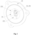
FIG. 2 is a structural schematic diagram of a water outlet adapter according to an embodiment of the present invention from a view. -
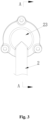
FIG. 3 is a structural schematic diagram of a water outlet adapter according to an embodiment of the present invention from another view. -
FIG. 4 is a sectional diagram ofFIG. 3 at position A. -
FIG. 5 is a structural schematic diagram of a water wheel structure in an embodiment of the present invention. -
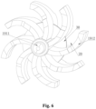
FIG. 6 is a structural schematic diagram of stirring blades according to an embodiment of the present invention. - In the drawings: 1-drum shaft; 2-water inlet pipe; 23-water outlet adapter; 231-transfer chamber; 232-water outlet of water outlet adapter; 24-water outlet of water inlet pipe; 7-motor; 8-drum support; 9-motor support structure; 19-stirring structure; 191-water wheel structure; 1911-rotating shaft; 1912-stirring blade; 1912a-first section blade; 1912b-second section blade; 1912c-third section blade; 20-stirring chamber; 30-reinforcing rib.
- It should be noted that these drawings and descriptions are not intended to limit the scope of the present disclosure in any way, but rather to illustrate the concept of the present disclosure by reference to specific embodiments for those skilled in the art.
- In order to make objects, technical solutions and advantages of the embodiments of the present invention clearer, the solutions in the embodiments are clearly and completely described as follows in combination with accompanying drawings in the embodiments of the present invention. The following embodiments are used for illustrating the present invention, rather than limiting the scope of the present invention.
- In the description of the present invention, it should be noted that, the orientation or positional relationship indicated by such terms as "up", "down", "front", "rear", "left", "right", "vertical", "inner" and "outer" is the orientation or positional relationship based on the accompanying drawings. Such terms are merely used for conveniently and simplified describing the present invention, rather than indicating or implying that the device or element referred to must be located in a certain orientation or must be constructed or operated in a certain orientation. Therefore, the terms cannot be understood as a limitation to the present invention.
- In the description of the present invention, it should be noted that, unless otherwise stipulated and defined definitely, such terms as "installed", "connected" and "in connection" should be understood in their broad sense, e.g., the connection can be a fixed connection, a detachable connection or an integral connection; can be mechanical connection or electrical connection; and can be direct connection or can be indirect connection through an intermediate. For those skilled in the art, specific meanings of the above terms in the present invention can be understood according to specific conditions.
- As shown in
FIG. 1 andFIG. 2 , the present invention provides a water inlet structure of a drum. The water inlet structure includes adrum shaft 1 in which there is a hollow to form a water inlet channel, and awater inlet pipe 2. A water outlet end of thewater inlet pipe 2 is provided with awater outlet adapter 23. Atransfer chamber 231 is provided inside thewater outlet adapter 23 and is communicated with the water inlet channel. A stirring structure 19 is provided inside thetransfer chamber 231 to stir the water inlet flow. - In the embodiment of the present invention, by arranging the stirring structure 19 inside the
transfer chamber 231, the water inlet flow is stirred by the stirring structure 19. The water inlet flow is broken up to increase the turbulence degree of the water inlet flow, thereby the water inlet flow is sufficiently mixed with the detergent, and improving the washing effect. - The
water outlet adapter 23 is integrally formed with thewater inlet pipe 2, thereby the resistance at a transition between thewater outlet adapter 23 and the water inlet is reduced, and the sealing property between thewater outlet adapter 23 and thewater inlet pipe 2 can be increased, and the water inlet flow is prevented from leaking out. Thewater outlet adapter 23 is provided at the outlet end of the inlet pipe, and thewater outlet adapter 23 can change the flow direction of the water inlet flow, so that the water flow from thewater inlet pipe 2 can enter into the water inlet channel in thedrum shaft 1 relatively smoothly. - It should be noted that, the
water inlet pipe 2 includes a first section water inlet pipe and a second section water inlet pipe. The first section water inlet pipe is a plastic pipe, and the second section water inlet pipe is a rubber pipe. The water outlet of the first section water inlet pipe has thewater outlet adapter 23, and the water inlet of the first section water inlet pipe has a rubber joint. The rubber joint of the first section water inlet pipe is integrally formed with the second section water inlet pipe. The second section water inlet pipe of thewater inlet pipe 2 is a rubber pipe which makes part of the water inlet pipe bending, so the position of thewater inlet pipe 2 is changed more flexibly. - As shown in
FIGS. 2 ,3 and4 , in an embodiment of the invention, thewater outlet adapter 23 is in the shape of a hemisphere. The diameter end surface of thewater outlet adapter 23 is provided with a water outlet being communicated with the water inlet channel. Thewater outlet 232 of the water outlet adapter is located at the center of the diameter end surface. The water outlet end of the water inlet pipe is embedded into thewater outlet adapter 23 along the direction perpendicular to the axis of the water outlet adapter, and the stirring structure 19 directly faces thewater outlet 232 of the water outlet adapter and thewater outlet 24 of the water inlet pipe. - In the embodiment of the present invention, the
water outlet adapter 23 is in the shape of a hemisphere. The inner wall of thewater outlet adapter 23 is in the shape of a circular arc, and the inner wall in the shape of a circular arc can reduce the frictional resistance to the water inlet flow. - The
water outlet adapter 23 is in the shape of a hemisphere, so that thewater outlet adapter 23 has an end face where the diameter is located, and the end face where the diameter is located is referred to as the diametric end surface. The diametric end surface is an end face where thewater outlet adapter 23 is the largest in size. The diametric end surface has a circular shape, and an inner circumference of the diametric end surface forms awater outlet 232 of the water outlet adapter having a circular shape. - The stirring structure 19 is provided at the
water outlet 232 of the water outlet adapter. The water inlet flow enters thetransfer chamber 231 and is stirred by the stirring structure 19 at thewater outlet 232 of the water outlet adapter, so that the water inlet flow into the water inlet channel from thetransfer chamber 231 has a large turbulence degree. - As an embodiment, the water outlet of the water outlet adapter and the water outlet of the water inlet pipe are both circular. A central line of the water outlet of the water outlet adapter and a central line of the water outlet of the water inlet pipe are both perpendicular to the shaft axis of the rotating shaft.
- As shown in
FIG. 2 andFIG. 5 , in the embodiment of the present invention, thewater wheel structure 191 includes arotating shaft 1911 rotatably provided at an inner wall of thewater outlet adapter 23 and a plurality of stirringblades 1912. Therotating shaft 1911 is extended radially within thetransfer chamber 231 and extended from an inner wall at one end of thewater outlet adapter 23 to an inner wall at an opposite end of thewater outlet adapter 23. The plurality of stirringblades 1912 are spaced on the outer circumferential wall of therotating shaft 1911 along the circumferential direction of therotating shaft 1911. - In an embodiment of the invention, specifically, the
water wheel structure 191 includes arotation shaft 1911 being rotatable within thetransfer chamber 231 andstirring blades 1912 being capable of rotating to stir the water inlet flow along with therotation shaft 1911. Therotating shaft 1911 is extended radially inside thetransfer chamber 231. One end of therotating shaft 1911 is rotationally connected with an inner wall of one end of thewater outlet adapter 23, and the other end of therotating shaft 1911 is rotationally connected with an inner wall of an opposite end of thewater outlet adapter 23, so that therotating shaft 1911 directly faces the water outlet. The water inlet flow needs to pass through the water flow structure before reaching thewater outlet 232 of the water outlet adapter. - As shown in
FIGS. 2 and4 , the water wheel structure has a rotating shaft rotatably disposed on an inner wall of the water outlet adapter. The rotating shaft is horizontally extended across the water outlet of the water outlet adapter from the inner wall of one side of the water outlet adapter to the inner wall of the opposite side of the water outlet adapter. - The
stirring blades 1912 are provided on an outer circumferential wall of therotating shaft 1911. Thestirring blades 1912 are integrally formed with therotating shaft 1911 to reduce resistance to the water inlet flow at a transition between thestirring blades 1912 and therotating shaft 1911. - The
stirring blades 1912 are provided on the outer circumferential wall of therotating shaft 1911 by one circle, so the maximum area of stirring of the water inlet flow can be got. Thestirring blades 1912 are evenly distributed on the outer circumferential wall of therotating shaft 1911, so that the stirring force for stirring the water inlet flow is relatively uniform. - Each of both ends of the
rotating shaft 1911 is provided with a mounting block., The mounting block includes a first mounting block and a second mounting block which are disposed coaxially. Both the first mounting block and the second mounting block are disc-shaped. A disc surface of the first mounting block is provided with the second mounting block axially protruded with respect to the first mounting block, and an insertion hole is arranged on the second mounting block in an axial direction. One end of therotating shaft 1911 is inserted into the insertion hole. The first mounting block is embedded on an inner wall of thewater outlet adapter 23, and can be driven to rotate inside thewater outlet adapter 23 by the motor to drive the rotatingshaft 1911 to rotate. Furthermore, the first mounting block is provided with a through hole being coaxial with and communicated with the insertion hole. One end of therotating shaft 1911 is rotatably inserted into the insertion hole, and the motor shaft of the motor is connected to the rotating shaft through the through hole, thereby driving the rotating shaft to rotate. - Preferably, the water inlet end of the
drum shaft 1 is inserted into thetransfer chamber 231 through thewater outlet 232 of the water outlet adapter. The water outlet end of the water inlet pipe is inserted into thetransfer chamber 231 in a tangential direction. The water from the water outlet of the water inlet pipe is supplied into thewater outlet adapter 23 in the tangential direction of the water outlet adapter, thereby the resistance caused by feeding water is reduced at the transition between the water outlet of the water inlet pipe and thewater outlet adapter 23, and the feeding efficiency of the water inlet pipe is improved. - Since the water-outlet end of the water inlet pipe is inserted into the
transfer chamber 231 in a tangential direction, so that the water inlet flow entering into thetransfer chamber 231 from the water outlet end of the water inlet pipe can directly flow toward thewater outlet 232 of the water outlet adapter. Thus it is avoided that the water inlet flow flows out of thewater outlet 232 of the water outlet adapter through multiple turns. - In addition, the water inlet end of the
drum shaft 1 is inserted into thetransfer chamber 231 through the water outlet of thewater outlet adapter 23, so that the sealing property between thedrum shaft 1 and thetransfer chamber 231 is increased, and the leakage of the water inlet flow is reduced. - In order that the stirring structure 19 stirs the water inlet flow of the
transfer chamber 231 to increase the turbulence degree of the water inlet flow, the rotation direction of thewater wheel structure 191 is set to be opposite to the flow direction of the water inlet flow. Thereby the rotation of thewater wheel structure 191 blocks and fluctuates the water inlet flow. - As shown in
FIGS. 2 and5 , in the embodiment of the present invention, each of thestirring blades 1912 is a plate-like structure and are gradually bent outwardly from the outer circumferential wall of therotating shaft 1911, and the bending directions of all thestirring blades 1912 are uniform. - In the embodiment of the present invention, specifically, the
stirring blade 1912 is a plate-like structure, and thestirring blade 1912 is protruded outward with respect to the outer circumferential wall of therotating shaft 1911. The length of the stirring arm is increased, and the turbulence degree of the water inlet flow is increased due to the increase in the stirring area for stirring the water inlet flow. - The
stirring blades 1912 are gradually bent outward from the outer circumferential wall of therotating shaft 1911, and the bending direction is opposite to the direction of the water inlet flow of therotating chamber 231. Thebent stirring blades 1912 are capable of not only collecting and blocking the water inlet flow, but also increasing the frictional blocking with the water inlet flow, and further increasing the turbulence degree of the water inlet flow. - As shown in
FIG. 5 , in an embodiment of the present invention, thestirring blade 1912 is divided into a first section blade 1912a, asecond section blade 1912b and athird section blade 1912c in a bending direction of thestirring blade 1912. The first section blade 1912a and thethird section blade 1912c are different in size in the bending direction of thestirring blade 1912, and thesecond section blade 1912b is gradually decreased in size in the bending direction of thestirring blade 1912. - In an embodiment of the invention, the
stirring blade 1912 is divided into three sections along the bending direction of thestirring blade 1912. Wherein the first section blade 1912a and thethird section blade 1912c are kept constant in size along the bending direction of thestirring blade 1912, and thesecond section blade 1912b is gradually reduced in size along the bending direction of thestirring blade 1912. The bending degree of thesecond section blade 1912b is the greatest to reduce the weight of thestirring blade 1912 on the one hand. - As shown in
FIG. 6 , in an embodiment of the present invention, the stirringchamber 20 is formed between twoadjacent stirring blades 1912, and the sizes of the stirringchambers 20 along the bending direction of thestirring blade 1912 are gradually increased. - In the embodiment of the present invention, the
stirring blades 1912 are spaced on the outer circumferential wall of therotating shaft 1911, so that twoadjacent stirring blades 1912 form the stirringchamber 20 between them. The stirringchamber 20 is a space for allowing the water inlet flow to reside, so that the water inlet flow can stay briefly in being stirred, and thestirring blades 1912 can stir the water inlet flow sufficiently. Due to the different bending degrees of the first section blades 1912a, thesecond section blades 1912b and the third section blades1912c, the size of the stirringchamber 20 in the bending direction of thestirring blades 1912 gradually increases. So the water inlet flow in the stirringchamber 20 is stirred by the twoadjacent stirring blades 1912. - In an embodiment of the present invention, a reinforcing
rib 30 is provided between twoadjacent stirring blades 1912. - In the embodiment of the present invention, the impact of the water inlet flow on the
stirring blades 1912 is greater during the stirring of the water inlet flow by thestirring blades 1912. Therefore, in order to increase the structural strength of thestirring blades 1912 and to reduce the cost, the reinforcingrib 30 is provided between twoadjacent stirring blades 1912. The reinforcingrib 30 can enhance the strength of the twostirring blades 1912 at the same time. - As shown in
FIG. 6 , in the embodiment of the present invention, the reinforcingrib 30 is of a plate-like structure, and the reinforcingrib 30 is extended in the bending direction of thestirring blade 1912 inside the stirringchamber 20. The reinforcingrib 30 is respectively fitted with the outer circumferential wall of therotating shaft 1911 and the twoadjacent stirring blades 1912. - In an embodiment of the invention, in particular, the reinforcing
rib 30 is of a plate-like structure. To maximize the strength of thestirring blade 1912, the arrangement of the reinforcingrib 30 is that the side walls of the reinforcingrib 30 corresponding to the outer circumferential wall of therotating shaft 1911, and the twoadjacent stirring blades 1912 is fitted with the outer circumferential wall of therotating shaft 1911, and the twoadjacent stirring blades 1912. Since the size of the stirringchamber 20 along the bending direction of thestirring blade 1912 is gradually reduced, thus, the size of the reinforcingrib 30 along the bending direction of thestirring blade 1912 is gradually reduced. - As shown in
FIG. 1 , the present invention also provides a drum washing machine. The drum washing machine includes a drum, adrum support 8 and amotor 7. Thedrum support 8 is provided outside the drum, and themotor 7 is provided on thedrum support 8. The drum washing machine further includes a water inlet structure of the drum. Thedrum shaft 1 is installed at the bottom of the drum, the water outlet end of thedrum shaft 1 is communicated with the drum, and a water inlet end of thedrum shaft 1 passes out of thedrum support 8 and is inserted into thetransfer chamber 231 with themotor 7. Thewater outlet adapter 23 is fixed to thedrum support 8. - In an embodiment of the present invention, the drum is a hole-free drum. The drum shaft is coaxially arranged at the drum bottom. The
motor 7 is arranged on the drum support by amotor support structure 9 which is wrapped outside themotor 7. Thewater outlet adapter 23 is fixed on thedrum support 8 by themotor support structure 9, and thewater outlet adapter 23 is provided outside themotor support structure 9. Thedrum support 8 includes an outer drum. - In feeding the water, the water inlet flow enters into the
water inlet pipe 2, thetransfer chamber 231, and thedrum shaft 1, and finally into the interior of the drum. - The embodiments merely describe preferred embodiments of the present invention, rather than limiting the concept and scope of the present invention. The preferred embodiments are disclosed above, and not used for limiting the present invention. Under the premise of not departing from the design idea of the present invention, various changes and improvements made to the technical solution of the present invention by those skilled in the art, such as simple amendment, equal change and modify according concept of the present invention, shall all fall within the protection scope of the present invention. The implementing solutions in the above embodiments can be further combined or substituted.
Claims (10)
- A water inlet structure of a drum, comprising, a drum shaft inside which there is hollow to form a water inlet channel, and a water inlet pipe, wherein,
a water outlet end of the water inlet pipe is provided with a water outlet adapter, a transfer chamber is provided inside the water outlet adapter and communicated with the water inlet channel, and a stirring structure is arranged inside the transfer chamber to stir the water inlet flow. - The water inlet structure of a drum according to claim 1, wherein, the water outlet adapter has a hemispherical shape,a water outlet is provided at a center of a diameter end surface of the water outlet adapter,a water outlet end of the water inlet pipe is embedded into the water outlet adapter along a direction perpendicular to a axis of the water outlet adapter, and the stirring structure faces directly to the water outlet of the water outlet adapter and the water outlet of the water inlet pipe.
- The water inlet structure of a drum according to claim 2, wherein, the stirring structure is a water wheel structure,a rotating shaft of the water wheel structure is rotatably disposed on an inner wall of the water outlet adapter,the rotating shaft is horizontally extended across the water outlet of the water outlet adapter from one side of the inner wall of the water outlet adapter to an opposite side of the inner wall of the water outlet adapter,preferably, both the water outlet of the water outlet adapter and the water outlet of the water inlet pipe are circular,a central line of the water outlet of the water outlet adapter and a central line of the water outlet of the water inlet pipe are both perpendicular to a shaft axis of the rotating shaft.
- The water inlet structure of a drum according to any one of claims 1-3, wherein, stirring blades are distributed at intervals along a circumferential direction of the rotating shaft on an outer circumferential wall of the rotating shaft.
- The water inlet structure of a drum according to claim 4, wherein, the stirring blade has a plate-like structure and is gradually bent outwardly from the outer circumferential wall of the rotating shaft, and the bending directions of all the stirring blades are uniform.
- The water inlet structure of a drum according to claim 5, wherein, the stirring blade is divided into a first section blade, a second section blade and a third section blade along the bending direction of the stirring blade,
the first section blade and the third section blade are different in size along the bending direction of the stirring blade, and the second section blade is gradually decreased in size along the bending direction of the stirring blade. - The water inlet structure of a drum according to claim 5, wherein, a stirring chamber is formed between two adjacent stirring blades, and the size of the stirring chamber gradually increases along the bending direction of the stirring blade.
- The water inlet structure of a drum according to any one of claims 1-7, wherein,, a reinforcing rib is provided between two adjacent stirring blades.
- The water inlet structure of a drum according to claim 8, wherein, the reinforcing rib is in a plate-like structure, and the reinforcing rib is extended in a bending direction of the stirring blade inside the stirring chamber, and the reinforcing rib is respectively fitted with the outer circumferential wall of the rotating shaft and two adjacent stirring blades.
- A drum washing machine, including a drum, a drum support and a motor, the drum support being provided outside the drum, and the motor being provided on the drum support, andfurther including a water inlet structure of the drum of any one of claims 1-9, wherein,a drum shaft is installed on a bottom of the drum, a water outlet end of the drum shaft is communicated with the drum, a water inlet end of the drum shaft passes out of the drum support and is inserted into the transfer chamber with the motor, and the water outlet adapter is fixed to the drum support.
Applications Claiming Priority (2)
| Application Number | Priority Date | Filing Date | Title |
|---|---|---|---|
| CN202011449253.9A CN114606730B (en) | 2020-12-09 | 2020-12-09 | Drum water inlet structure and drum washing machine |
| PCT/CN2021/129310 WO2022121595A1 (en) | 2020-12-09 | 2021-11-08 | Water inlet structure of drum, and front load washing machine |
Publications (2)
| Publication Number | Publication Date |
|---|---|
| EP4261339A1 true EP4261339A1 (en) | 2023-10-18 |
| EP4261339A4 EP4261339A4 (en) | 2024-05-15 |
Family
ID=81856629
Family Applications (1)
| Application Number | Title | Priority Date | Filing Date |
|---|---|---|---|
| EP21902302.5A Pending EP4261339A4 (en) | 2020-12-09 | 2021-11-08 | WATER INLET STRUCTURE OF A DRUM AND FRONT LOADING WASHING MACHINE |
Country Status (3)
| Country | Link |
|---|---|
| EP (1) | EP4261339A4 (en) |
| CN (1) | CN114606730B (en) |
| WO (1) | WO2022121595A1 (en) |
Family Cites Families (15)
| Publication number | Priority date | Publication date | Assignee | Title |
|---|---|---|---|---|
| JPH025997A (en) * | 1988-06-27 | 1990-01-10 | Toshiba Corp | Washer |
| DE3934434A1 (en) * | 1989-10-14 | 1991-04-18 | Licentia Gmbh | Washing machine with conical water-tight drum - in which double-walled drum consists of cylindrical perforated inner wall and conical outer jacket |
| CN2320636Y (en) * | 1998-03-11 | 1999-05-26 | 无锡小天鹅股份有限公司 | Agitated washing machine |
| CN102182049B (en) * | 2011-05-10 | 2012-07-11 | 李耀强 | Detergent feeding and mixing device |
| CN102995348B (en) * | 2012-11-30 | 2013-08-28 | 李守林 | Water circulation device as well as water circulation simulated manual washing device and working method thereof |
| CN103911818B (en) * | 2014-03-04 | 2016-01-27 | 江苏神农灭菌设备股份有限公司 | The sterilizing of drum-type sterilization washing machine and on-line cleaning device |
| CN105986432B (en) * | 2015-03-05 | 2018-11-06 | 海信(山东)冰箱有限公司 | A kind of tumbling-box washing machine |
| CN105200725B (en) * | 2015-09-01 | 2018-06-22 | 无锡小天鹅股份有限公司 | For the detergent box of washing machine and with its washing machine |
| CN105200723B (en) * | 2015-09-01 | 2018-04-20 | 无锡小天鹅股份有限公司 | Washing machine |
| CN207227775U (en) * | 2017-09-18 | 2018-04-13 | 无锡小天鹅股份有限公司 | Detergent throwing device and there is its washing machine |
| CN109629181A (en) * | 2017-10-09 | 2019-04-16 | 无锡小天鹅股份有限公司 | Device for clothing processing |
| CN108866923B (en) * | 2018-02-07 | 2020-04-14 | 无锡小天鹅电器有限公司 | Drum washing machine |
| CN110607644B (en) * | 2018-06-15 | 2022-05-06 | 青岛海尔洗涤电器有限公司 | Front-loading washing machine and its inner drum assembly |
| CN108978132B (en) * | 2018-09-27 | 2024-12-27 | 青岛海尔洗护电器有限公司 | External liquid storage box and household appliances |
| TR201918205A2 (en) * | 2019-11-21 | 2021-06-21 | Vestel Beyaz Esya Sanayi Ve Ticaret Anonim Sirketi | A swivel joint for white goods. |
-
2020
- 2020-12-09 CN CN202011449253.9A patent/CN114606730B/en active Active
-
2021
- 2021-11-08 WO PCT/CN2021/129310 patent/WO2022121595A1/en not_active Ceased
- 2021-11-08 EP EP21902302.5A patent/EP4261339A4/en active Pending
Also Published As
| Publication number | Publication date |
|---|---|
| CN114606730A (en) | 2022-06-10 |
| WO2022121595A1 (en) | 2022-06-16 |
| CN114606730B (en) | 2025-08-26 |
| EP4261339A4 (en) | 2024-05-15 |
Similar Documents
| Publication | Publication Date | Title |
|---|---|---|
| EP2314747B1 (en) | Pulsator device usable with washing machine and washing machine having the same | |
| CN106958117B (en) | Interior tub assembly, tub assembly and the washing machine of washing machine | |
| CA2994839C (en) | Magnetic drive, seal-less pump | |
| CN110093751A (en) | Rotary drum washing machine and its flow-guiding structure | |
| CN105350213A (en) | Anti-winding impeller type washing machine with box-shaped detergent dissolver | |
| CN114606730B (en) | Drum water inlet structure and drum washing machine | |
| KR20050012392A (en) | Structure for engaging spider to drum of drum type washer | |
| CN112127109A (en) | A washing assembly, a washing tub assembly and a washing machine | |
| CN222668461U (en) | Impeller, drainage pump and air conditioner | |
| CN114484819B (en) | jet device, air conditioner | |
| CN217459926U (en) | Washing machine | |
| CN105350225A (en) | Anti-winding impeller type washing machine with box-shaped detergent dissolver | |
| CN105350246A (en) | Anti-winding washing machine with box-shaped detergent dissolver | |
| CN108755000B (en) | Drum washing machine and control method thereof | |
| CN208003830U (en) | Piglet preweaning feed produces super grease and adds high efficient mixer | |
| CN105369526A (en) | Pulsator washing machine with box type washing powder dissolver | |
| CN105369542A (en) | Anti-winding pulsator washing machine with box type washing powder dissolver | |
| KR200146677Y1 (en) | A washing machine | |
| CN105350219A (en) | Anti-winding impeller type washing machine with box-shaped detergent instant dissolver | |
| CN105350215A (en) | Anti-winding impeller type washing machine with box-shaped detergent dissolver | |
| CN105350232A (en) | Impeller type washing machine with box-shaped detergent dissolver | |
| CN105350216A (en) | Anti-winding impeller type washing machine with box-shaped detergent instant dissolver | |
| CN105350244A (en) | Anti-winding impeller type washing machine with box-shaped detergent instant dissolver | |
| CN105350238A (en) | Anti-winding impeller type washing machine with box-shaped detergent dissolver | |
| CN105369514A (en) | Anti-winding pulsator washing machine with box type washing powder dissolver |
Legal Events
| Date | Code | Title | Description |
|---|---|---|---|
| STAA | Information on the status of an ep patent application or granted ep patent |
Free format text: STATUS: THE INTERNATIONAL PUBLICATION HAS BEEN MADE |
|
| PUAI | Public reference made under article 153(3) epc to a published international application that has entered the european phase |
Free format text: ORIGINAL CODE: 0009012 |
|
| STAA | Information on the status of an ep patent application or granted ep patent |
Free format text: STATUS: REQUEST FOR EXAMINATION WAS MADE |
|
| 17P | Request for examination filed |
Effective date: 20230707 |
|
| AK | Designated contracting states |
Kind code of ref document: A1 Designated state(s): AL AT BE BG CH CY CZ DE DK EE ES FI FR GB GR HR HU IE IS IT LI LT LU LV MC MK MT NL NO PL PT RO RS SE SI SK SM TR |
|
| DAV | Request for validation of the european patent (deleted) | ||
| DAX | Request for extension of the european patent (deleted) | ||
| A4 | Supplementary search report drawn up and despatched |
Effective date: 20240416 |
|
| RIC1 | Information provided on ipc code assigned before grant |
Ipc: D06F 39/02 20060101ALI20240410BHEP Ipc: D06F 39/08 20060101AFI20240410BHEP |
|
| STAA | Information on the status of an ep patent application or granted ep patent |
Free format text: STATUS: EXAMINATION IS IN PROGRESS |
|
| 17Q | First examination report despatched |
Effective date: 20250818 |