EP4261133A1 - Deicing systems and methods for an aircraft - Google Patents
Deicing systems and methods for an aircraft Download PDFInfo
- Publication number
- EP4261133A1 EP4261133A1 EP23164644.9A EP23164644A EP4261133A1 EP 4261133 A1 EP4261133 A1 EP 4261133A1 EP 23164644 A EP23164644 A EP 23164644A EP 4261133 A1 EP4261133 A1 EP 4261133A1
- Authority
- EP
- European Patent Office
- Prior art keywords
- icing
- detector
- signal
- control unit
- aircraft
- Prior art date
- Legal status (The legal status is an assumption and is not a legal conclusion. Google has not performed a legal analysis and makes no representation as to the accuracy of the status listed.)
- Granted
Links
Images


Classifications
-
- B—PERFORMING OPERATIONS; TRANSPORTING
- B64—AIRCRAFT; AVIATION; COSMONAUTICS
- B64D—EQUIPMENT FOR FITTING IN OR TO AIRCRAFT; FLIGHT SUITS; PARACHUTES; ARRANGEMENT OR MOUNTING OF POWER PLANTS OR PROPULSION TRANSMISSIONS IN AIRCRAFT
- B64D15/00—De-icing or preventing icing on exterior surfaces of aircraft
- B64D15/20—Means for detecting icing or initiating de-icing
- B64D15/22—Automatic initiation by icing detector
-
- B—PERFORMING OPERATIONS; TRANSPORTING
- B64—AIRCRAFT; AVIATION; COSMONAUTICS
- B64D—EQUIPMENT FOR FITTING IN OR TO AIRCRAFT; FLIGHT SUITS; PARACHUTES; ARRANGEMENT OR MOUNTING OF POWER PLANTS OR PROPULSION TRANSMISSIONS IN AIRCRAFT
- B64D15/00—De-icing or preventing icing on exterior surfaces of aircraft
- B64D15/02—De-icing or preventing icing on exterior surfaces of aircraft by ducted hot gas or liquid
- B64D15/04—Hot gas application
-
- B—PERFORMING OPERATIONS; TRANSPORTING
- B64—AIRCRAFT; AVIATION; COSMONAUTICS
- B64D—EQUIPMENT FOR FITTING IN OR TO AIRCRAFT; FLIGHT SUITS; PARACHUTES; ARRANGEMENT OR MOUNTING OF POWER PLANTS OR PROPULSION TRANSMISSIONS IN AIRCRAFT
- B64D15/00—De-icing or preventing icing on exterior surfaces of aircraft
- B64D15/12—De-icing or preventing icing on exterior surfaces of aircraft by electric heating
-
- B—PERFORMING OPERATIONS; TRANSPORTING
- B64—AIRCRAFT; AVIATION; COSMONAUTICS
- B64D—EQUIPMENT FOR FITTING IN OR TO AIRCRAFT; FLIGHT SUITS; PARACHUTES; ARRANGEMENT OR MOUNTING OF POWER PLANTS OR PROPULSION TRANSMISSIONS IN AIRCRAFT
- B64D15/00—De-icing or preventing icing on exterior surfaces of aircraft
- B64D15/20—Means for detecting icing or initiating de-icing
-
- B—PERFORMING OPERATIONS; TRANSPORTING
- B64—AIRCRAFT; AVIATION; COSMONAUTICS
- B64D—EQUIPMENT FOR FITTING IN OR TO AIRCRAFT; FLIGHT SUITS; PARACHUTES; ARRANGEMENT OR MOUNTING OF POWER PLANTS OR PROPULSION TRANSMISSIONS IN AIRCRAFT
- B64D43/00—Arrangements or adaptations of instruments
Definitions
- Examples of the present disclosure generally relate to systems and methods for deicing portions of an aircraft.
- Aircraft are used to transport passengers and cargo between various locations.
- Various aircraft include icing detectors that are used to determine icing conditions on various portions of the aircraft, such as portions of an engine, wings, and the like.
- ice protection systems are activated to remove or otherwise reduce the ice on the portions of the aircraft.
- Certain regulations such as promulgated by the United States Federal Aviation Administration (FAA), define atmospheric envelopes in which icing conditions are considered for aircraft design and certification. Accumulation of ice on certain surfaces, such as aircraft wings and engine inlets, may affect performance of the aircraft. Icing conditions can exist in different forms, such as supercooled liquid water, ice crystals, or a mixture of the two.
- FAA Federal Aviation Administration
- Ice accumulation on a leading edge of a wing can impact lift and drag characteristics, while ice accumulation on an engine inlet or ingestion of ice crystals into the engine can reduce thrust. Additionally, ice accretion on air data probes can cause erroneous air data measurements. As such, real-time detection of icing conditions is used to ensure safe and efficient operation of an aircraft.
- the distinct icing types have different and unique effects on an aircraft, which can pose a risk to transport category commercial aircraft at all temperatures and conditions within FAA icing regulations, for example but not limited to, 14 CFR Part 25, Appendix C, O and 14 CFR Part 33 Appendix D icing envelopes.
- Known aircraft typically use an ice accretion sensor that includes a probe designed to collect supercooled water droplets on the probe surface. However, the probe is typically unable to detect ice crystals within the Appendix D icing envelope.
- certain examples of the present disclosure provide a system including a first icing detector configured to detect a first icing condition in relation to one or more portions of an aircraft.
- the first icing detector is configured to output a first icing signal indicative of the first icing condition.
- a second icing detector is configured to detect a second icing condition in relation to the one or more portions of the aircraft.
- the second icing detector is configured to output a second icing signal indicative of the second icing condition.
- a control unit is in communication with the first icing detector and the second icing detector.
- the control unit is configured to receive the first icing signal from the first icing detector and the second icing signal from the second icing detector.
- the control unit is further configured to distinguish between presence of supercooled liquid water and ice crystal icing in response to receiving one or both of the first icing signal or the second icing signal.
- the first icing detector is an icing conditions detector configured to detect both ice water content and liquid water content
- the second icing detector is a magnetostrictive ice detector configured to detect the liquid water content.
- the icing conditions detector is unable to differentiate between the ice water content and the liquid water content
- the magnetostrictive ice detector is unable to detect the ice water content.
- the system also includes one or more deicers in communication with the control unit.
- the one or more deicers are configured to deice the one or more portions of the aircraft.
- the control unit is further configured to automatically operate the one or more deicers in response to receiving one or both of the first icing signal or the second icing signal.
- the one or more deicers include a first deicer configured to deice a first portion of the aircraft, and a second deicer configured to deice a second portion of the aircraft.
- the first portion of the aircraft includes one or more portions of an engine or a wing
- the second portion of the aircraft includes one or more portion of the other of the engine or the wing.
- the system can also include a user interface having one or both of a display or a speaker.
- the control unit can be further configured to, based on the icing conditions, one or both of show information on the display or broadcast the information from the speaker.
- control unit is configured to determine the presence of the supercooled liquid water and potentially the ice crystal icing in response to receiving both the first icing signal and the second icing signal.
- control unit is configured to determine the presence of the ice crystal icing in response to receiving the first icing signal but not the second icing signal.
- control unit is configured to determine an error condition in response to receiving the second icing signal but not the first icing signal.
- Certain examples of the present disclosure provide a method including communicatively coupling a control unit with a first icing detector, wherein the first icing detector is configured to detect a first icing condition in relation to one or more portions of an aircraft, and wherein the first icing detector is configured to output a first icing signal indicative of the first icing condition; communicatively coupling the control unit with a second icing detector, wherein the second icing detector is configured to detect a second icing condition in relation to the one or more portions of the aircraft, wherein the second icing detector is configured to output a second icing signal indicative of the second icing condition; receiving, by the control unit, one or both of the first icing signal from the first icing detector and the second icing signal from the second icing detector; and distinguishing, by the control unit, between presence of supercooled liquid water and ice crystal icing in response to receiving one or both of the first icing signal or the second icing signal.
- Certain examples of the present disclosure provide an aircraft including a system for distinguishing icing conditions as described herein.
- Examples of the present disclosure provide systems and methods for detecting aircraft icing, in various forms, and distinguishing between different icing conditions.
- the systems and methods include first and second icing detectors in communication with a control unit, which is configured to differentiate between supercooled liquid water and ice crystal icing conditions.
- the control unit is further configured to output signals to airframe and engine ice protection systems.
- examples of the present disclosure are configured to identify and differentiate between both glaciated ice crystals and supercooled liquid water, and thereby provide a health check for an aircraft, including various systems, engines, and the like. Further, the systems and methods described herein are able to detect different phases of water. As such, examples of the present disclosure are independent of drop size or temperature, and can therefore function in any icing conditions (for example, Appendix C, Appendix O, or Appendix D).
- systems and methods described herein increase flight deck crew situational awareness, in contrast to known systems, which rely on memory items and checklists. Additionally, the systems and methods described herein lead to reduced power and/or fuel consumption due to optimized activation of the ice protection systems.
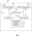
- FIG. 1 illustrates a schematic block diagram of a system 100 for deicing one or more portions of an aircraft 102, according to an example of the present disclosure.
- the system 100 includes a first icing detector 104 and a second icing detector 106.
- a control unit 108 is in communication with the first icing detector 104 and the second icing detector 106, such as through one or more wired or wireless connections.
- the control unit 108 is further in communication with a first deicer 110 and a second deicer 112, such as through one or more wired or wireless connections.
- the control unit 108 is also in communication with a user interface 114, such as can be part of a computer workstation, a flight deck computer, or the like.
- the user interface 114 can be located in a cockpit or flight deck of the aircraft 102.
- the deicers 110 and 112 can be any types of devices, systems, or the like configured to deice portions of an aircraft. Examples of the deicers 110 and 112 include anti-ice systems, ice prevention systems, deicing devices and systems, and/or the like.
- the first icing detector 104 includes one or more probes, sensors, or the like that are configured to detect a first icing condition.
- the first icing detector 104 is an icing conditions detector that is configured to detect both ice water content and liquid water content. While such an icing conditions detector is configured to detect ice water content and liquid water content, the icing conditions detector may not be able to differentiate between ice water content and liquid water content.
- the second icing detector 106 includes one or more probes, sensors, or the like that are configured to detect a second icing condition, which may differ from the first icing condition.
- the second icing detector 106 is an accretion based ice detector, such as a magnetostrictive ice detector, which can detect liquid water content, but not ice water content. Ice accretion on a magnetostrictive ice detector builds and sheds in cycles. Typically, when a magnetostrictive ice detector is used, an engine anti-ice operation is performed before a wing anti-ice operation.
- control unit 108 is in communication with one or more deicers that are configured to deice one or more portions of the aircraft 102.
- the first deicer 110 is configured to deice one or more first portions of the aircraft 102.
- the first deicer 110 is, or is part of, an ice protection system.
- the first deicer 110 is configured to deice one or more portions of an engine of the aircraft 102.
- the first deicer 110 can include one or more heaters, heating coils, heating mats, pneumatic heaters, hot air blowers, and/or the like.
- the second deicer 112 is configured to deicer one or more second portions of the aircraft 102.
- the second deicer 112 is or is part of an ice protection system.
- the second deicer 112 is configured to deice one or more portions of a wing of the aircraft 102.
- the second deicer 112 can include one or more heaters, heating coils, heating mats, pneumatic heaters, hot air blowers, and/or the like.
- the first deicer 110 is configured to deice or more portions of a wing of the aircraft 102
- the second deicer 112 is configured to deice or more portions of the engine of the aircraft 102
- the control unit 108 can be in communication with more or less deicers than shown.
- the control unit 108 can be in communication with only the first deicer 110 or the second deicer 112.
- the control unit 108 can be in communication with three or more deicers, each of which is configured to deice a different portion of the aircraft 102.
- the user interface 114 can be part of a computer workstation, a flight computer, and/or the like within the aircraft 102.
- the user interface 114 includes a display 116, such as an electronic monitor, screen, television, or the like, and a speaker 118 (for example, an audio speaker, loudspeaker, and/or the like).
- the user interface 114 may include only one of the display 116 or the speaker 118.
- the first icing detector 104 is configured to detect the first icing condition and the second icing detector 106 is configured to detect the second icing condition.
- the first icing detector 104 In response to detecting the first icing condition, the first icing detector 104 outputs a first icing signal 120 indicative of the first icing condition.
- the second icing detector 106 In response to detecting the second icing condition, the second icing detector 106 outputs a second icing signal 122 indicative of the second icing condition.
- the control unit 108 receives the first icing signal 120 and the second icing signal 122 from the first icing detector 104 and the second icing detector 106, respectively.
- the control unit 108 differentiates between presence of liquid water content (such as supercooled liquid water) and ice crystal formation (for example, ice crystal icing) based on receiving one or both of the first icing signal 120 and the second icing signal 122.
- the control unit 108 operates the first deicer 110 and the second deicer 112 in response to receiving one or both of the first icing signal 120 and/or the second icing signal 122.
- the control unit 108 also outputs one or more information signals 124 to the user interface 114.
- the information signals 124 are indicative of information based on the icing conditions. Such information can be shown on the display 116 and/or broadcast through the speaker 118.
- the control unit 108 can differentiate between icing conditions but not automatically operate one or more deicers in response thereto.
- the control unit 108 determines the presence of supercooled liquid water and potentially ice crystals on one or more surfaces of the aircraft 102.
- the control unit 108 can then automatically operate the first deicer 110, such as to remove ice from one or more portions of an engine, and the second deicer 112, such as to remove ice from one or more surfaces of a wing.
- the system 100 reduces overuse (and therefore energy consumption) of the deicers, as both the first icing signal 120 and the second icing signal 122 are received in order to activate both the first deicer 110 and the second deicer 112.
- the control unit 108 can further output one or more information signals 124 indicating potential for ice building on edges of windscreens and wiper blades, which can be shown on the display 116 and/or broadcast via the speaker 118.
- the control unit 108 in response to the receiving both the first icing signal 120 and the second icing signal 122, the control unit 108 automatically operates the first deicer 110 to remove, prevent, and/or otherwise reduce icing in relation to an engine of the aircraft 102.
- the control unit 108 can then activate the second deicer 112 based on the cycles of the first deicer 110.
- the first deicer 110 can be activated after two detection cycles, and the second deicer 112 can be activated after eight additional detection cycles.
- the first deicer 120 can be activated in fewer or more than two detections cycles, and the second deicer 112 can be activated in fewer or more than eight additional detection cycles.
- the control unit 108 determines the presence of ice crystals. For example, if liquid water content was present, then the control unit 108 would also receive the second icing signal 122 from the second icing detector 106. Because the first icing detector 104 is able to detect both ice water content and liquid water content, reception of the first icing signal 120 indicative of the first icing condition necessarily means that ice water content is present, but not liquid water content.
- the control unit 108 can differentiate between ice water content and liquid water content through analysis of the first icing signal 120 and the second icing signal 122. In particular, if both the first icing signal 120 and the second icing signal 122 are received, the control unit 108 determines that both supercooled liquid water content and potentially ice crystals are present on one or more portions of the aircraft 102. If, however, only the first icing signal 120 is received, but not the second icing signal 122, the control unit 108 determines that ice crystals are present on or more portions of the aircraft 102.
- control unit 108 automatically operates one or both of the first deicer 110 or the second deicer 112 to remove, prevent, or otherwise reduce potential ice formation on one or more portions of the aircraft 102.
- the control unit 108 can further output the one or more information signals 124 to the user interface 114, in order to display and/or broadcast information regarding activation of the one or more deicers, for example.
- the information signals 124 can also include information regarding effects in relation to various portions of the aircraft 102.
- the control unit 108 determines an error condition, which may require maintenance.
- the first icing detector 104 is configured to detect both ice water content and liquid water content
- the second icing detector 106 is configured to detect only liquid water content.
- the control unit 108 determines a malfunction of one or both of the first icing detector 104 and/or the second icing detector 106.
- the control unit 108 outputs the one or more information signals 124 which include an alert message indicating the potential of an error.
- control unit central processing unit
- CPU central processing unit
- computer computer
- RISC reduced instruction set computers
- ASICs application specific integrated circuits
- the control unit 108 may be or include one or more processors that are configured to control operation, as described herein.
- the control unit 108 is configured to execute a set of instructions that are stored in one or more data storage units or elements (such as one or more memories), in order to process data.
- the control unit 108 may include or be coupled to one or more memories.
- the data storage units may also store data or other information as desired or needed.
- the data storage units may be in the form of an information source or a physical memory element within a processing machine.
- the set of instructions may include various commands that instruct the control unit 108 as a processing machine to perform specific operations such as the methods and processes of the various examples of the subject matter described herein.
- the set of instructions may be in the form of a software program.
- the software may be in various forms such as system software or application software. Further, the software may be in the form of a collection of separate programs, a program subset within a larger program, or a portion of a program.
- the software may also include modular programming in the form of object-oriented programming.
- the processing of input data by the processing machine may be in response to user commands, or in response to results of previous processing, or in response to a request made by another processing machine.
- the diagrams of examples herein may illustrate one or more control or processing units, such as the control unit 108.
- the processing or control units may represent circuits, circuitry, or portions thereof that may be implemented as hardware with associated instructions (e.g., software stored on a tangible and (optionally, non-transitory) computer readable storage medium, such as a computer hard drive, ROM, RAM, or the like) that perform the operations described herein.
- the hardware may include state machine circuitry hardwired to perform the functions described herein.
- the hardware may include electronic circuits that include and/or are connected to one or more logic-based devices, such as microprocessors, processors, controllers, or the like.
- control unit 108 may represent processing circuitry such as one or more of a field programmable gate array (FPGA), application specific integrated circuit (ASIC), microprocessor(s), and/or the like.
- FPGA field programmable gate array
- ASIC application specific integrated circuit
- microprocessor(s) and/or the like.
- the circuits in various examples may be configured to execute one or more algorithms to perform functions described herein.
- the one or more algorithms may include aspects of examples disclosed herein, whether or not expressly identified in a flowchart or a method.
- the terms "software” and “firmware” are interchangeable, and include any computer program stored in a data storage unit (for example, one or more memories) for execution by a computer, including RAM memory, ROM memory, EPROM memory, EEPROM memory, and non-volatile RAM (NVRAM) memory.
- a data storage unit for example, one or more memories
- NVRAM non-volatile RAM
- the above data storage unit types are exemplary only, and are thus not limiting as to the types of memory usable for storage of a computer program.
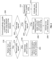
- Figure 2 illustrates a flow chart of a method for deicing one or more portions of an aircraft, according to an example of the present disclosure.
- the control unit 108 is communicatively coupled to the first icing detector 104 and the second icing detector 106.
- the control unit 108 determines if the first icing signal 120 indicative of the first icing condition is received. If the first icing signal 120 is received at 202, the control unit 108 next determines at 204 if the second icing signal 122 indicative of the second icing condition is received.
- the method proceeds to 206, at which the control unit 108 determines that supercooled liquid water content and potential ice crystal icing is present on one or more surfaces of the aircraft 102.
- the control unit 108 then activates one or more deicers, such as the first deicer 110 and/or the second deicer 112, in response thereto.
- the control unit 108 can trigger an internal engine function, such as raising idle speed.
- the method proceeds to 210, at which the control unit 108 determines the presence of ice crystal icing.
- the control unit 108 then activates the one or more deicers, such as the first deicer 110 and/or the second deicer 112, in response thereto.
- the control unit 108 can trigger an internal engine function, such as raising idle speed.
- the method proceeds to 214, at which the control unit 108 determines if the second icing signal 122 has been received. If the first icing signal 120 is not received at 202 and the second icing signal 122 is not received at 214, the control unit 108 determines that no icing conditions are present, and refrains from activating the deicers at 216.
- the control unit 108 determines an error condition at 218.
- the error condition may be a scenario that requires maintenance, such as to check and potentially repair one or both of the ice detectors 104 and 106. Accordingly, the method may then proceed from 218 to 220, at which the control unit 108 outputs an information signal 124 indicating the error condition to the user interface 114.
- the error condition can be shown on the display 116 and/or broadcast through the speaker 118.
- the method can also include message to individuals, such as pilots, regarding the operations described herein.
- the messages can be shown on a display and/or broadcast through a speaker.
- Figure 3 illustrates a perspective front view of the aircraft 102, according to an example of the present disclosure.
- the aircraft 102 includes a propulsion system 312 that includes engines 314, for example.
- one or more first deicers 110 (shown in Figure 1 ) are operatively coupled to one or more of the engines 314.
- the propulsion system 312 may include more engines 314 than shown.
- the engines 314 are carried by wings 316 of the aircraft 102.
- one or more second deicers 112 (shown in Figure 1 ) are operatively coupled to one or both of the wings 316.
- the engines 314 may be carried by a fuselage 318 and/or an empennage 320.
- the empennage 320 may also support horizontal stabilizers 322 and a vertical stabilizer 324.
- the fuselage 318 of the aircraft 102 defines an internal cabin 330, which includes a flight deck or cockpit, one or more work sections (for example, galleys, personnel carry-on baggage areas, and the like), one or more passenger sections (for example, first class, business class, and coach sections), one or more lavatories, and/or the like.
- the user interface 114 shown in Figure 1 is within the internal cabin 330, such as within the flight deck.
- Figure 3 shows an example of an aircraft 102. It is to be understood that the aircraft 102 can be sized, shaped, and configured differently than shown in Figure 3 .
- Figure 4 illustrates a perspective lateral view of a nose 340 of the aircraft 102, according to an example of the present disclosure.
- the first icing detector 104 and the second icing detector 106 can be located proximate to the nose 340.
- the first icing detector 104 and the second icing detector 106 can be disposed below a window 342 of the flight deck and above a front landing gear 344.
- the first icing detector 104 and the second icing detector 106 can be on the same side of the aircraft 102.
- the first icing detector 104 can be on a first side of the aircraft 102
- the second icing detector 106 can be on a second side of the aircraft 102.
- the first icing detector 104 and the second icing detector 106 can be at various other locations of the aircraft 102, such as on a top of the fuselage, on one or more engines, one or more wings, and/or the like.
- examples of the present disclosure provide systems and methods that are able to distinguish between different types of icing conditions, such as supercooled water and ice crystals. Further, examples of the present disclosure provide systems and methods for detecting icing in various forms and operating deicers in response thereto.
- a structure, limitation, or element that is "configured to” perform a task or operation is particularly structurally formed, constructed, or adapted in a manner corresponding to the task or operation.
- an object that is merely capable of being modified to perform the task or operation is not “configured to” perform the task or operation as used herein.
Landscapes
- Engineering & Computer Science (AREA)
- Aviation & Aerospace Engineering (AREA)
- Investigating Or Analyzing Materials By The Use Of Electric Means (AREA)
- Arrangements For Transmission Of Measured Signals (AREA)
- Traffic Control Systems (AREA)
Abstract
Description
- Examples of the present disclosure generally relate to systems and methods for deicing portions of an aircraft.
- Aircraft are used to transport passengers and cargo between various locations. Various aircraft include icing detectors that are used to determine icing conditions on various portions of the aircraft, such as portions of an engine, wings, and the like. In response to detection of icing conditions, ice protection systems are activated to remove or otherwise reduce the ice on the portions of the aircraft.
- Certain regulations, such as promulgated by the United States Federal Aviation Administration (FAA), define atmospheric envelopes in which icing conditions are considered for aircraft design and certification. Accumulation of ice on certain surfaces, such as aircraft wings and engine inlets, may affect performance of the aircraft. Icing conditions can exist in different forms, such as supercooled liquid water, ice crystals, or a mixture of the two.
- Ice accumulation on a leading edge of a wing can impact lift and drag characteristics, while ice accumulation on an engine inlet or ingestion of ice crystals into the engine can reduce thrust. Additionally, ice accretion on air data probes can cause erroneous air data measurements. As such, real-time detection of icing conditions is used to ensure safe and efficient operation of an aircraft.
- The distinct icing types have different and unique effects on an aircraft, which can pose a risk to transport category commercial aircraft at all temperatures and conditions within FAA icing regulations, for example but not limited to, 14 CFR Part 25, Appendix C, O and 14 CFR Part 33 Appendix D icing envelopes. Known aircraft typically use an ice accretion sensor that includes a probe designed to collect supercooled water droplets on the probe surface. However, the probe is typically unable to detect ice crystals within the Appendix D icing envelope.
- A need exists for an icing detection system and method that is able to distinguish between different types of icing conditions, such as supercooled water and ice crystals. Further, a need exists for a system and a method for detecting aircraft icing in various forms, and operating deicers in response thereto.
- With those needs in mind, certain examples of the present disclosure provide a system including a first icing detector configured to detect a first icing condition in relation to one or more portions of an aircraft. The first icing detector is configured to output a first icing signal indicative of the first icing condition. A second icing detector is configured to detect a second icing condition in relation to the one or more portions of the aircraft. The second icing detector is configured to output a second icing signal indicative of the second icing condition. A control unit is in communication with the first icing detector and the second icing detector. The control unit is configured to receive the first icing signal from the first icing detector and the second icing signal from the second icing detector. The control unit is further configured to distinguish between presence of supercooled liquid water and ice crystal icing in response to receiving one or both of the first icing signal or the second icing signal.
- In at least one example, the first icing detector is an icing conditions detector configured to detect both ice water content and liquid water content, and the second icing detector is a magnetostrictive ice detector configured to detect the liquid water content. In at least one further example, the icing conditions detector is unable to differentiate between the ice water content and the liquid water content, and the magnetostrictive ice detector is unable to detect the ice water content.
- In at least one example, the system also includes one or more deicers in communication with the control unit. The one or more deicers are configured to deice the one or more portions of the aircraft. In at least one further example, the control unit is further configured to automatically operate the one or more deicers in response to receiving one or both of the first icing signal or the second icing signal. In at least one example, the one or more deicers include a first deicer configured to deice a first portion of the aircraft, and a second deicer configured to deice a second portion of the aircraft. As an example, the first portion of the aircraft includes one or more portions of an engine or a wing, and the second portion of the aircraft includes one or more portion of the other of the engine or the wing.
- The system can also include a user interface having one or both of a display or a speaker. The control unit can be further configured to, based on the icing conditions, one or both of show information on the display or broadcast the information from the speaker.
- In at least one example, the control unit is configured to determine the presence of the supercooled liquid water and potentially the ice crystal icing in response to receiving both the first icing signal and the second icing signal.
- In at least one example, the control unit is configured to determine the presence of the ice crystal icing in response to receiving the first icing signal but not the second icing signal.
- In at least one example, the control unit is configured to determine an error condition in response to receiving the second icing signal but not the first icing signal.
- Certain examples of the present disclosure provide a method including communicatively coupling a control unit with a first icing detector, wherein the first icing detector is configured to detect a first icing condition in relation to one or more portions of an aircraft, and wherein the first icing detector is configured to output a first icing signal indicative of the first icing condition; communicatively coupling the control unit with a second icing detector, wherein the second icing detector is configured to detect a second icing condition in relation to the one or more portions of the aircraft, wherein the second icing detector is configured to output a second icing signal indicative of the second icing condition; receiving, by the control unit, one or both of the first icing signal from the first icing detector and the second icing signal from the second icing detector; and distinguishing, by the control unit, between presence of supercooled liquid water and ice crystal icing in response to receiving one or both of the first icing signal or the second icing signal.
- Certain examples of the present disclosure provide an aircraft including a system for distinguishing icing conditions as described herein.
-
-
Figure 1 illustrates a schematic block diagram of a system for deicing one or more portions of an aircraft, according to an example of the present disclosure. -
Figure 2 illustrates a flow chart of a method for deicing one or more portions of an aircraft, according to an example of the present disclosure. -
Figure 3 illustrates a perspective front view of the aircraft, according to an example of the present disclosure. -
Figure 4 illustrates a perspective lateral view of a nose of the aircraft, according to an example of the present disclosure. - The foregoing summary, as well as the following detailed description of certain examples will be better understood when read in conjunction with the appended drawings. As used herein, an element or step recited in the singular and preceded by the word "a" or "an" should be understood as not necessarily excluding the plural of the elements or steps. Further, references to "one example" are not intended to be interpreted as excluding the existence of additional examples that also incorporate the recited features. Moreover, unless explicitly stated to the contrary, examples "comprising" or "having" an element or a plurality of elements having a particular condition can include additional elements not having that condition.
- Examples of the present disclosure provide systems and methods for detecting aircraft icing, in various forms, and distinguishing between different icing conditions. The systems and methods include first and second icing detectors in communication with a control unit, which is configured to differentiate between supercooled liquid water and ice crystal icing conditions. The control unit is further configured to output signals to airframe and engine ice protection systems.
- In contrast to known ice detection systems, examples of the present disclosure are configured to identify and differentiate between both glaciated ice crystals and supercooled liquid water, and thereby provide a health check for an aircraft, including various systems, engines, and the like. Further, the systems and methods described herein are able to detect different phases of water. As such, examples of the present disclosure are independent of drop size or temperature, and can therefore function in any icing conditions (for example, Appendix C, Appendix O, or Appendix D).
- Also, the systems and methods described herein increase flight deck crew situational awareness, in contrast to known systems, which rely on memory items and checklists. Additionally, the systems and methods described herein lead to reduced power and/or fuel consumption due to optimized activation of the ice protection systems.
-
Figure 1 illustrates a schematic block diagram of asystem 100 for deicing one or more portions of anaircraft 102, according to an example of the present disclosure. Thesystem 100 includes afirst icing detector 104 and asecond icing detector 106. Acontrol unit 108 is in communication with thefirst icing detector 104 and thesecond icing detector 106, such as through one or more wired or wireless connections. Thecontrol unit 108 is further in communication with afirst deicer 110 and asecond deicer 112, such as through one or more wired or wireless connections. In at least one example, thecontrol unit 108 is also in communication with auser interface 114, such as can be part of a computer workstation, a flight deck computer, or the like. For example, theuser interface 114 can be located in a cockpit or flight deck of theaircraft 102. - The
deicers deicers - The
first icing detector 104 includes one or more probes, sensors, or the like that are configured to detect a first icing condition. In at least one example, thefirst icing detector 104 is an icing conditions detector that is configured to detect both ice water content and liquid water content. While such an icing conditions detector is configured to detect ice water content and liquid water content, the icing conditions detector may not be able to differentiate between ice water content and liquid water content. - The
second icing detector 106 includes one or more probes, sensors, or the like that are configured to detect a second icing condition, which may differ from the first icing condition. In at least one example, thesecond icing detector 106 is an accretion based ice detector, such as a magnetostrictive ice detector, which can detect liquid water content, but not ice water content. Ice accretion on a magnetostrictive ice detector builds and sheds in cycles. Typically, when a magnetostrictive ice detector is used, an engine anti-ice operation is performed before a wing anti-ice operation. - As noted, the
control unit 108 is in communication with one or more deicers that are configured to deice one or more portions of theaircraft 102. For example, thefirst deicer 110 is configured to deice one or more first portions of theaircraft 102. Thefirst deicer 110 is, or is part of, an ice protection system. In at least one example, thefirst deicer 110 is configured to deice one or more portions of an engine of theaircraft 102. Thefirst deicer 110 can include one or more heaters, heating coils, heating mats, pneumatic heaters, hot air blowers, and/or the like. - The
second deicer 112 is configured to deicer one or more second portions of theaircraft 102. Thesecond deicer 112 is or is part of an ice protection system. In at least one example, thesecond deicer 112 is configured to deice one or more portions of a wing of theaircraft 102. Thesecond deicer 112 can include one or more heaters, heating coils, heating mats, pneumatic heaters, hot air blowers, and/or the like. - Optionally, the
first deicer 110 is configured to deice or more portions of a wing of theaircraft 102, and thesecond deicer 112 is configured to deice or more portions of the engine of theaircraft 102. Also, optionally, thecontrol unit 108 can be in communication with more or less deicers than shown. For example, thecontrol unit 108 can be in communication with only thefirst deicer 110 or thesecond deicer 112. As another example, thecontrol unit 108 can be in communication with three or more deicers, each of which is configured to deice a different portion of theaircraft 102. - As noted, the
user interface 114 can be part of a computer workstation, a flight computer, and/or the like within theaircraft 102. Theuser interface 114 includes adisplay 116, such as an electronic monitor, screen, television, or the like, and a speaker 118 (for example, an audio speaker, loudspeaker, and/or the like). Optionally, theuser interface 114 may include only one of thedisplay 116 or thespeaker 118. - In operation, the
first icing detector 104 is configured to detect the first icing condition and thesecond icing detector 106 is configured to detect the second icing condition. In response to detecting the first icing condition, thefirst icing detector 104 outputs afirst icing signal 120 indicative of the first icing condition. Similarly, in response to detecting the second icing condition, thesecond icing detector 106 outputs asecond icing signal 122 indicative of the second icing condition. Thecontrol unit 108 receives thefirst icing signal 120 and thesecond icing signal 122 from thefirst icing detector 104 and thesecond icing detector 106, respectively. As described herein, thecontrol unit 108 differentiates between presence of liquid water content (such as supercooled liquid water) and ice crystal formation (for example, ice crystal icing) based on receiving one or both of thefirst icing signal 120 and thesecond icing signal 122. In at least one example, in response, thecontrol unit 108 operates thefirst deicer 110 and thesecond deicer 112 in response to receiving one or both of thefirst icing signal 120 and/or thesecond icing signal 122. In at least one example, thecontrol unit 108 also outputs one or more information signals 124 to theuser interface 114. The information signals 124 are indicative of information based on the icing conditions. Such information can be shown on thedisplay 116 and/or broadcast through thespeaker 118. Optionally, thecontrol unit 108 can differentiate between icing conditions but not automatically operate one or more deicers in response thereto. - In response to the
control unit 108 receiving thefirst icing signal 120 indicative of the first icing condition from the first icing detector 104 (such as an icing conditions detector that is configured to detect both ice water content and liquid water content), and thesecond icing signal 122 indicative of the second icing condition from the second icing detector 106 (such as a magnetostrictive ice detector that is only able to detect liquid water content), thecontrol unit 108 determines the presence of supercooled liquid water and potentially ice crystals on one or more surfaces of theaircraft 102. Accordingly, thecontrol unit 108 can then automatically operate thefirst deicer 110, such as to remove ice from one or more portions of an engine, and thesecond deicer 112, such as to remove ice from one or more surfaces of a wing. In this manner, thesystem 100 reduces overuse (and therefore energy consumption) of the deicers, as both thefirst icing signal 120 and thesecond icing signal 122 are received in order to activate both thefirst deicer 110 and thesecond deicer 112. Thecontrol unit 108 can further output one or more information signals 124 indicating potential for ice building on edges of windscreens and wiper blades, which can be shown on thedisplay 116 and/or broadcast via thespeaker 118. - In at least one example, in response to the receiving both the
first icing signal 120 and thesecond icing signal 122, thecontrol unit 108 automatically operates thefirst deicer 110 to remove, prevent, and/or otherwise reduce icing in relation to an engine of theaircraft 102. Thecontrol unit 108 can then activate thesecond deicer 112 based on the cycles of thefirst deicer 110. As a non-limiting example, thefirst deicer 110 can be activated after two detection cycles, and thesecond deicer 112 can be activated after eight additional detection cycles. In other examples, thefirst deicer 120 can be activated in fewer or more than two detections cycles, and thesecond deicer 112 can be activated in fewer or more than eight additional detection cycles. - In response to the
control unit 108 receiving thefirst icing signal 120 indicative of the first icing condition, but not thesecond icing signal 122 indicative of the second icing condition (that is, thecontrol unit 108 only receives the first icing signal 120), thecontrol unit 108 determines the presence of ice crystals. For example, if liquid water content was present, then thecontrol unit 108 would also receive thesecond icing signal 122 from thesecond icing detector 106. Because thefirst icing detector 104 is able to detect both ice water content and liquid water content, reception of thefirst icing signal 120 indicative of the first icing condition necessarily means that ice water content is present, but not liquid water content. In this manner, thecontrol unit 108 can differentiate between ice water content and liquid water content through analysis of thefirst icing signal 120 and thesecond icing signal 122. In particular, if both thefirst icing signal 120 and thesecond icing signal 122 are received, thecontrol unit 108 determines that both supercooled liquid water content and potentially ice crystals are present on one or more portions of theaircraft 102. If, however, only thefirst icing signal 120 is received, but not thesecond icing signal 122, thecontrol unit 108 determines that ice crystals are present on or more portions of theaircraft 102. In either scenario, thecontrol unit 108 automatically operates one or both of thefirst deicer 110 or thesecond deicer 112 to remove, prevent, or otherwise reduce potential ice formation on one or more portions of theaircraft 102. Thecontrol unit 108 can further output the one or more information signals 124 to theuser interface 114, in order to display and/or broadcast information regarding activation of the one or more deicers, for example. The information signals 124 can also include information regarding effects in relation to various portions of theaircraft 102. - In response to the
control unit 108 receiving thesecond icing signal 122 from thesecond icing detector 106, but not thefirst icing signal 120 from thefirst icing detector 104, thecontrol unit 108 determines an error condition, which may require maintenance. For example, thefirst icing detector 104 is configured to detect both ice water content and liquid water content, while thesecond icing detector 106 is configured to detect only liquid water content. By receiving thesecond icing signal 122 from the second icing detector indicating the presence of liquid water content, but not thefirst icing signal 120 which would otherwise also detect the presence of liquid water content, thecontrol unit 108 determines a malfunction of one or both of thefirst icing detector 104 and/or thesecond icing detector 106. In response, thecontrol unit 108 outputs the one or more information signals 124 which include an alert message indicating the potential of an error. - As used herein, the term "control unit," "central processing unit," "CPU," "computer," or the like may include any processor-based or microprocessor-based system including systems using microcontrollers, reduced instruction set computers (RISC), application specific integrated circuits (ASICs), logic circuits, and any other circuit or processor including hardware, software, or a combination thereof capable of executing the functions described herein. Such are exemplary only, and are thus not intended to limit in any way the definition and/or meaning of such terms. For example, the
control unit 108 may be or include one or more processors that are configured to control operation, as described herein. - The
control unit 108 is configured to execute a set of instructions that are stored in one or more data storage units or elements (such as one or more memories), in order to process data. For example, thecontrol unit 108 may include or be coupled to one or more memories. The data storage units may also store data or other information as desired or needed. The data storage units may be in the form of an information source or a physical memory element within a processing machine. - The set of instructions may include various commands that instruct the
control unit 108 as a processing machine to perform specific operations such as the methods and processes of the various examples of the subject matter described herein. The set of instructions may be in the form of a software program. The software may be in various forms such as system software or application software. Further, the software may be in the form of a collection of separate programs, a program subset within a larger program, or a portion of a program. The software may also include modular programming in the form of object-oriented programming. The processing of input data by the processing machine may be in response to user commands, or in response to results of previous processing, or in response to a request made by another processing machine. - The diagrams of examples herein may illustrate one or more control or processing units, such as the
control unit 108. It is to be understood that the processing or control units may represent circuits, circuitry, or portions thereof that may be implemented as hardware with associated instructions (e.g., software stored on a tangible and (optionally, non-transitory) computer readable storage medium, such as a computer hard drive, ROM, RAM, or the like) that perform the operations described herein. The hardware may include state machine circuitry hardwired to perform the functions described herein. Optionally, the hardware may include electronic circuits that include and/or are connected to one or more logic-based devices, such as microprocessors, processors, controllers, or the like. Optionally, thecontrol unit 108 may represent processing circuitry such as one or more of a field programmable gate array (FPGA), application specific integrated circuit (ASIC), microprocessor(s), and/or the like. The circuits in various examples may be configured to execute one or more algorithms to perform functions described herein. The one or more algorithms may include aspects of examples disclosed herein, whether or not expressly identified in a flowchart or a method. - As used herein, the terms "software" and "firmware" are interchangeable, and include any computer program stored in a data storage unit (for example, one or more memories) for execution by a computer, including RAM memory, ROM memory, EPROM memory, EEPROM memory, and non-volatile RAM (NVRAM) memory. The above data storage unit types are exemplary only, and are thus not limiting as to the types of memory usable for storage of a computer program.
-
Figure 2 illustrates a flow chart of a method for deicing one or more portions of an aircraft, according to an example of the present disclosure. Referring toFigures 1 and2 , at 200, thecontrol unit 108 is communicatively coupled to thefirst icing detector 104 and thesecond icing detector 106. At 202, thecontrol unit 108 determines if thefirst icing signal 120 indicative of the first icing condition is received. If thefirst icing signal 120 is received at 202, thecontrol unit 108 next determines at 204 if thesecond icing signal 122 indicative of the second icing condition is received. If the second icing signal is also received at 204, the method proceeds to 206, at which thecontrol unit 108 determines that supercooled liquid water content and potential ice crystal icing is present on one or more surfaces of theaircraft 102. At 208, thecontrol unit 108 then activates one or more deicers, such as thefirst deicer 110 and/or thesecond deicer 112, in response thereto. Optionally and/or additionally, at 208, instead of deicers being activated, thecontrol unit 108 can trigger an internal engine function, such as raising idle speed. - If, however, the
second icing signal 122 is not detected at 204, the method proceeds to 210, at which thecontrol unit 108 determines the presence of ice crystal icing. At 212, thecontrol unit 108 then activates the one or more deicers, such as thefirst deicer 110 and/or thesecond deicer 112, in response thereto. Optionally and/or additionally, at 212, instead of deicers being activated, thecontrol unit 108 can trigger an internal engine function, such as raising idle speed. - If, however, the
first icing signal 120 is not received at 202, the method proceeds to 214, at which thecontrol unit 108 determines if thesecond icing signal 122 has been received. If thefirst icing signal 120 is not received at 202 and thesecond icing signal 122 is not received at 214, thecontrol unit 108 determines that no icing conditions are present, and refrains from activating the deicers at 216. - If, however, the
first icing signal 120 is not received at 202, but thesecond icing signal 122 is received at 214, thecontrol unit 108 determines an error condition at 218. The error condition may be a scenario that requires maintenance, such as to check and potentially repair one or both of theice detectors control unit 108 outputs aninformation signal 124 indicating the error condition to theuser interface 114. The error condition can be shown on thedisplay 116 and/or broadcast through thespeaker 118. - The method can also include message to individuals, such as pilots, regarding the operations described herein. The messages can be shown on a display and/or broadcast through a speaker.
-
Figure 3 illustrates a perspective front view of theaircraft 102, according to an example of the present disclosure. Theaircraft 102 includes apropulsion system 312 that includesengines 314, for example. In at least one example, one or more first deicers 110 (shown inFigure 1 ) are operatively coupled to one or more of theengines 314. Optionally, thepropulsion system 312 may includemore engines 314 than shown. Theengines 314 are carried bywings 316 of theaircraft 102. In at least one example, one or more second deicers 112 (shown inFigure 1 ) are operatively coupled to one or both of thewings 316. - In other embodiments, the
engines 314 may be carried by afuselage 318 and/or anempennage 320. Theempennage 320 may also supporthorizontal stabilizers 322 and avertical stabilizer 324. Thefuselage 318 of theaircraft 102 defines aninternal cabin 330, which includes a flight deck or cockpit, one or more work sections (for example, galleys, personnel carry-on baggage areas, and the like), one or more passenger sections (for example, first class, business class, and coach sections), one or more lavatories, and/or the like. Theuser interface 114 shown inFigure 1 is within theinternal cabin 330, such as within the flight deck. -
Figure 3 shows an example of anaircraft 102. It is to be understood that theaircraft 102 can be sized, shaped, and configured differently than shown inFigure 3 . -
Figure 4 illustrates a perspective lateral view of anose 340 of theaircraft 102, according to an example of the present disclosure. Thefirst icing detector 104 and thesecond icing detector 106 can be located proximate to thenose 340. For example, thefirst icing detector 104 and thesecond icing detector 106 can be disposed below awindow 342 of the flight deck and above afront landing gear 344. Thefirst icing detector 104 and thesecond icing detector 106 can be on the same side of theaircraft 102. Optionally, thefirst icing detector 104 can be on a first side of theaircraft 102, and thesecond icing detector 106 can be on a second side of theaircraft 102. Optionally, thefirst icing detector 104 and thesecond icing detector 106 can be at various other locations of theaircraft 102, such as on a top of the fuselage, on one or more engines, one or more wings, and/or the like. - Further, the disclosure comprises the subject matter described in the following clauses:
- Clause 1. A system comprising: a first icing detector configured to detect a first icing condition in relation to one or more portions of an aircraft, wherein the first icing detector is configured to output a first icing signal indicative of the first icing condition; a second icing detector configured to detect a second icing condition in relation to the one or more portions of the aircraft, wherein the second icing detector is configured to output a second icing signal indicative of the second icing condition; and a control unit in communication with the first icing detector and the second icing detector, wherein the control unit is configured to receive the first icing signal from the first icing detector and the second icing signal from the second icing detector, and wherein the control unit is further configured to distinguish between presence of supercooled liquid water and ice crystal icing in response to receiving one or both of the first icing signal or the second icing signal.
- Clause 2. The system of Clause 1, wherein the first icing detector is an icing conditions detector configured to detect both ice water content and liquid water content, and wherein the second icing detector is a magnetostrictive ice detector configured to detect the liquid water content.
- Clause 3. The system of Clause 2, wherein the icing conditions detector is unable to differentiate between the ice water content and the liquid water content, and wherein the magnetostrictive ice detector is unable to detect the ice water content.
- Clause 4. The system of any of Clauses 1-3, further comprising one or more deicers in communication with the control unit, wherein the one or more deicers are configured to deice the one or more portions of the aircraft.
- Clause 5. The system of Clause 4, wherein the control unit is further configured to automatically operate the one or more deicers in response to receiving one or both of the first icing signal or the second icing signal.
- Clause 6. The system of Clauses 4 or 5, wherein the one or more deicers comprise: a first deicer configured to deice a first portion of the aircraft; and a second deicer configured to deice a second portion of the aircraft.
-
Clause 7. The system of Clause 6, wherein the first portion of the aircraft comprises one or more portions of an engine or a wing, and wherein the second portion of the aircraft comprises one or more portion of the other of the engine or the wing. - Clause 8. The system of any of Clauses 1-7, further comprising a user interface having one or both of a display or a speaker, wherein, based on the icing conditions, the control unit is further configured to one or both of show information on the display or broadcast the information from the speaker.
- Clause 9. The system of any of Clauses 1-8, wherein the control unit is configured to determine the presence of the supercooled liquid water and potentially the ice crystal icing in response to receiving both the first icing signal and the second icing signal.
- Clause 9a. The system of any of Clauses 1-8, wherein, in response to receiving both the first icing signal and the second icing signal, the control unit is configured to determine the presence of the supercooled liquid water and potential ice crystal icing.
- Clause 9b. The system of any of Clauses 1-9a, wherein, in response to receiving both the first icing signal and the second icing signal, the control unit is configured to determine the presence of the supercooled liquid water and ice crystal icing.
- Clause 10. The system of any of Clauses 1-9b, wherein the control unit is configured to determine the presence of the ice crystal icing in response to receiving the first icing signal but not the second icing signal.
- Clause 11. The system of any of Clauses 1-10, wherein the control unit is configured to determine an error condition in response to receiving the second icing signal but not the first icing signal.
- Clause 11a. The system of any of Clauses 1-11, arranged to carry out the method of any of Clauses 12-19.
- Clause 12. A method comprising: communicatively coupling a control unit with a first icing detector, wherein the first icing detector is configured to detect a first icing condition in relation to one or more portions of an aircraft, and wherein the first icing detector is configured to output a first icing signal indicative of the first icing condition; communicatively coupling the control unit with a second icing detector, wherein the second icing detector is configured to detect a second icing condition in relation to the one or more portions of the aircraft, wherein the second icing detector is configured to output a second icing signal indicative of the second icing condition; receiving, by the control unit, one or both of the first icing signal from the first icing detector and the second icing signal from the second icing detector; and distinguishing, by the control unit, between presence of supercooled liquid water and ice crystal icing in response to receiving one or both of the first icing signal or the second icing signal.
- Clause 13. The method of Clause 12, wherein the first icing detector is an icing conditions detector configured to detect both ice water content and liquid water content, wherein the icing conditions detector is unable to differentiate between the ice water content and the liquid water content, wherein the second icing detector is a magnetostrictive ice detector configured to detect the liquid water content, and wherein the magnetostrictive ice detector is unable to detect the ice water content.
- Clause 14. The method of Clause 12 or 13, further comprising operating one or more deicers to deice the one or more portions of the aircraft.
- Clause 15. The method of Clause 14, wherein said operating comprises automatically operating, by the control unit, the one or more deicers in response to receiving one or both of the first icing signal or the second icing signal.
- Clause 16. The method of Clause 15, wherein the one or more deicers comprise:
a first deicer configured to deice a one or more portions of an engine or a wing of the aircraft; and a second deicer configured to deice one or more portion of the other of the engine or the wing of the aircraft. - Clause 17. The method of any of Clauses 12-16, wherein said distinguishing comprises determining the presence of the supercooled liquid water and potentially the ice crystal icing in response to receiving both the first icing signal and the second icing signal.
- Clause 17a. The method of any of Clauses 12-16, wherein said distinguishing comprises, in response to receiving both the first icing signal and the second icing signal, determining the presence of the supercooled liquid water and potential ice crystal icing.
- Clause 17b. The method of any of Clauses 12-17a, wherein said distinguishing comprises, in response to receiving both the first icing signal and the second icing signal, determining the presence of the supercooled liquid water and ice crystal icing.
- Clause 18. The method of any of Clauses 12-17b, wherein said distinguishing comprises determining the presence of the ice crystal icing in response to receiving the first icing signal but not the second icing signal.
- Clause 19. The method of any of Clauses 12-18, wherein said distinguishing comprises determining an error condition in response to receiving the second icing signal but not the first icing signal.
- Clause 19a. The method of any of Clauses 12-18, performed using the system of any of Clauses 1-11.
- Clause 20. An aircraft comprising: a first icing detector configured to detect a first icing condition in relation to one or more portions of the aircraft, wherein the first icing detector is configured to output a first icing signal indicative of the first icing condition; a second icing detector configured to detect a second icing condition in relation to the one or more portions of the aircraft, wherein the second icing detector is configured to output a second icing signal indicative of the second icing condition; a control unit in communication with the first icing detector and the second icing detector, wherein the control unit is configured to: receive the first icing signal from the first icing detector and the second icing signal from the second icing detector; distinguish between presence of supercooled liquid water and ice crystal icing in response to receiving one or both of the first icing signal or the second icing signal; determine the presence of the supercooled liquid water and potentially the ice crystal icing in response to receiving both the first icing signal and the second icing signal; determine the presence of the ice crystal icing in response to receiving the first icing signal but not the second icing signal; and determine an error condition in response to receiving the second icing signal but not the first icing signal; one or more deicers in communication with the control unit, wherein the one or more deicers are configured to deice the one or more portions of the aircraft, wherein the control unit is further configured to automatically operate the one or more deicers in response to receiving one or both of the first icing signal or the second icing signal; and a user interface having one or both of a display or a speaker, wherein, based on the icing conditions, the control unit is further configured to one or both of show information on the display or broadcast the information from the speaker.
- Clause 21. The aircraft of Clause 20, arranged to carry out the method of any of Clauses 12-19.
- Clause 22. An aircraft comprising: the system of any of Clauses 1-11a.
- Clause 23. The aircraft of Clause 22, wherein the control unit is further configured to: determine the presence of the supercooled liquid water and potential ice crystal icing in response to receiving both the first icing signal and the second icing signal; determine the presence of the ice crystal icing in response to receiving the first icing signal but not the second icing signal; and determine an error condition in response to receiving the second icing signal but not the first icing signal, and wherein the aircraft further comprises: one or more deicers in communication with the control unit, wherein the one or more deicers are configured to deice the one or more portions of the aircraft, wherein the control unit is further configured to automatically operate the one or more deicers in response to receiving one or both of the first icing signal or the second icing signal; and a user interface having one or both of a display or a speaker, wherein, based on the icing conditions, the control unit is further configured to one or both of show information on the display or broadcast the information from the speaker.
- As described herein, examples of the present disclosure provide systems and methods that are able to distinguish between different types of icing conditions, such as supercooled water and ice crystals. Further, examples of the present disclosure provide systems and methods for detecting icing in various forms and operating deicers in response thereto.
- While various spatial and directional terms, such as top, bottom, lower, mid, lateral, horizontal, vertical, front and the like can be used to describe examples of the present disclosure, it is understood that such terms are merely used with respect to the orientations shown in the drawings. The orientations can be inverted, rotated, or otherwise changed, such that an upper portion is a lower portion, and vice versa, horizontal becomes vertical, and the like.
- As used herein, a structure, limitation, or element that is "configured to" perform a task or operation is particularly structurally formed, constructed, or adapted in a manner corresponding to the task or operation. For purposes of clarity and the avoidance of doubt, an object that is merely capable of being modified to perform the task or operation is not "configured to" perform the task or operation as used herein.
- It is to be understood that the above description is intended to be illustrative, and not restrictive. For example, the above-described examples (and/or aspects thereof) can be used in combination with each other. In addition, many modifications can be made to adapt a particular situation or material to the teachings of the various examples of the disclosure without departing from their scope. While the dimensions and types of materials described herein are intended to define the parameters of the various examples of the disclosure, the examples are by no means limiting and are exemplary examples. Many other examples will be apparent to those of skill in the art upon reviewing the above description. The scope of the various examples of the disclosure should, therefore, be determined with reference to the appended claims, along with the full scope of equivalents to which such claims are entitled. In the appended claims and the detailed description herein, the terms "including" and "in which" are used as the plain-English equivalents of the respective terms "comprising" and "wherein." Moreover, the terms "first," "second," and "third," etc. are used merely as labels, and are not intended to impose numerical requirements on their objects.
- This written description uses examples to disclose the various examples of the disclosure, including the best mode, and also to enable any person skilled in the art to practice the various examples of the disclosure, including making and using any devices or systems and performing any incorporated methods. The patentable scope of the various examples of the disclosure is defined by the claims, and can include other examples that occur to those skilled in the art. Such other examples are intended to be within the scope of the claims if the examples have structural elements that do not differ from the literal language of the claims, or if the examples include equivalent structural elements with insubstantial differences from the literal language of the claims.
Claims (15)
- A system (100) comprising:a first icing detector (104) configured to detect a first icing condition in relation to one or more portions of an aircraft (102), wherein the first icing detector (104) is configured to output a first icing signal (120) indicative of the first icing condition;a second icing detector (106) configured to detect a second icing condition in relation to the one or more portions of the aircraft (102), wherein the second icing detector (106) is configured to output a second icing signal (122) indicative of the second icing condition; anda control unit (108) in communication with the first icing detector (104) and the second icing detector (106), wherein the control unit (108) is configured to receive the first icing signal (120) from the first icing detector (104) and the second icing signal (122) from the second icing detector (106), and wherein the control unit (108) is further configured to distinguish between presence of supercooled liquid water and ice crystal icing in response to receiving one or both of the first icing signal (120) or the second icing signal (122).
- The system (100) of claim 1, wherein the first icing detector (104) is an icing conditions detector configured to detect both ice water content and liquid water content, and wherein the second icing detector (106) is a magnetostrictive ice detector configured to detect the liquid water content.
- The system (100) of claim 2, wherein the icing conditions detector is unable to differentiate between the ice water content and the liquid water content, and wherein the magnetostrictive ice detector is unable to detect the ice water content.
- The system (100) of any of claims 1-3, further comprising one or more deicers in communication with the control unit (108), wherein the one or more deicers are configured to deice the one or more portions of the aircraft (102).
- The system (100) of claim 4, wherein the control unit (108) is further configured to automatically operate the one or more deicers in response to receiving one or both of the first icing signal (120) or the second icing signal (122).
- The system (100) of any of claims 1-5, further comprising a user interface (114) having one or both of a display (116) or a speaker (118), wherein, based on the icing conditions, the control unit (108) is further configured to one or both of show information on the display (116) or broadcast the information from the speaker (118).
- The system (100) of any of claims 1-6, wherein, in response to receiving both the first icing signal (120) and the second icing signal (122), the control unit (108) is configured to determine the presence of the supercooled liquid water and potential ice crystal icing.
- The system (100) of any one of claims 1-7, wherein the control unit (108) is configured to determine the presence of the ice crystal icing in response to receiving the first icing signal (120) but not the second icing signal (122).
- A method comprising:communicatively coupling a control unit (108) with a first icing detector (104), wherein the first icing detector (104) is configured to detect a first icing condition in relation to one or more portions of an aircraft (102), and wherein the first icing detector (104) is configured to output a first icing signal (120) indicative of the first icing condition;communicatively coupling the control unit (108) with a second icing detector (106), wherein the second icing detector (106) is configured to detect a second icing condition in relation to the one or more portions of the aircraft (102), wherein the second icing detector (106) is configured to output a second icing signal (122) indicative of the second icing condition;receiving, by the control unit (108), one or both of the first icing signal (120) from the first icing detector (104) and the second icing signal (122) from the second icing detector (106); anddistinguishing, by the control unit (108), between presence of supercooled liquid water and ice crystal icing in response to receiving one or both of the first icing signal (120) or the second icing signal (122).
- The method of claim 9, wherein the first icing detector (104) is an icing conditions detector configured to detect both ice water content and liquid water content, wherein the icing conditions detector is unable to differentiate between the ice water content and the liquid water content, wherein the second icing detector (106) is a magnetostrictive ice detector configured to detect the liquid water content, and wherein the magnetostrictive ice detector is unable to detect the ice water content.
- The method of claims 9 or 10, further comprising operating one or more deicers to deice the one or more portions of the aircraft (102).
- The method of claim 11, wherein said operating comprises automatically operating, by the control unit (108), the one or more deicers in response to receiving one or both of the first icing signal (120) or the second icing signal (122).
- The method of any of claims 9-12, wherein said distinguishing comprises, in response to receiving both the first icing signal (120) and the second icing signal (122), determining the presence of the supercooled liquid water and potential ice crystal icing.
- The method of any of claims 9-13, wherein said distinguishing comprises determining the presence of the ice crystal icing in response to receiving the first icing signal (120) but not the second icing signal (122).
- An aircraft (102) comprising:the system (100) of any of claims 1-8, wherein the control unit (108) is further configured to:determine the presence of the supercooled liquid water and potential ice crystal icing in response to receiving both the first icing signal (120) and the second icing signal (122);determine the presence of the ice crystal icing in response to receiving the first icing signal (120) but not the second icing signal (122); anddetermine an error condition in response to receiving the second icing signal (122) but not the first icing signal (120);one or more deicers in communication with the control unit (108), wherein the one or more deicers are configured to deice the one or more portions of the aircraft (102), wherein the control unit (108) is further configured to automatically operate the one or more deicers in response to receiving one or both of the first icing signal (120) or the second icing signal (122); anda user interface (114) having one or both of a display (116) or a speaker (118), wherein, based on the icing conditions, the control unit (108) is further configured to one or both of show information on the display (116) or broadcast the information from the speaker (118).
Applications Claiming Priority (1)
| Application Number | Priority Date | Filing Date | Title |
|---|---|---|---|
| US17/717,202 US11912420B2 (en) | 2022-04-11 | 2022-04-11 | Deicing systems and methods for an aircraft |
Publications (2)
| Publication Number | Publication Date |
|---|---|
| EP4261133A1 true EP4261133A1 (en) | 2023-10-18 |
| EP4261133B1 EP4261133B1 (en) | 2025-03-05 |
Family
ID=85778962
Family Applications (1)
| Application Number | Title | Priority Date | Filing Date |
|---|---|---|---|
| EP23164644.9A Active EP4261133B1 (en) | 2022-04-11 | 2023-03-28 | Deicing systems and methods for an aircraft |
Country Status (4)
| Country | Link |
|---|---|
| US (1) | US11912420B2 (en) |
| EP (1) | EP4261133B1 (en) |
| CN (1) | CN116890994A (en) |
| CA (1) | CA3192103A1 (en) |
Families Citing this family (1)
| Publication number | Priority date | Publication date | Assignee | Title |
|---|---|---|---|---|
| US20240017840A1 (en) * | 2022-07-15 | 2024-01-18 | Rosemount Aerospace Inc. | Temperature-based suppression of spurious ice signals |
Citations (4)
| Publication number | Priority date | Publication date | Assignee | Title |
|---|---|---|---|---|
| US20050218268A1 (en) * | 2004-03-31 | 2005-10-06 | Rosemount Aerospace Inc. | Ice detector for improved ice detection at near freezing condition |
| US20140007654A1 (en) * | 2012-07-06 | 2014-01-09 | Lyle E. Lilie | Cloud Ice Detector |
| US20170370960A1 (en) * | 2016-06-28 | 2017-12-28 | Rosemount Aerospace, Inc. | Air data sensing probe with icing condition detector |
| US20190039742A1 (en) * | 2017-08-01 | 2019-02-07 | Honeywell International Inc. | Managing response to icing threat |
Family Cites Families (10)
| Publication number | Priority date | Publication date | Assignee | Title |
|---|---|---|---|---|
| DE60329634D1 (en) * | 2003-08-20 | 2009-11-19 | Boeing Co | METHOD AND SYSTEMS FOR DETERMINING TEMPERING CONDITIONS |
| US7643941B2 (en) * | 2006-01-11 | 2010-01-05 | Science Engineering Associates, Inc. | Cloud water characterization system |
| US9180972B2 (en) * | 2012-01-05 | 2015-11-10 | The Boeing Company | Supercooled large drop icing condition detection system |
| US9227733B2 (en) * | 2013-01-02 | 2016-01-05 | The Boeing Company | Automated water drop measurement and ice detection system |
| US9884685B2 (en) * | 2014-05-28 | 2018-02-06 | The Boeing Company | External case heater for an angle of attack sensor |
| US9242735B1 (en) * | 2014-08-28 | 2016-01-26 | The Boeing Company | Detecting inflight icing conditions on aircraft |
| US10737793B2 (en) * | 2015-12-02 | 2020-08-11 | The Boeing Company | Aircraft ice detection systems and methods |
| US9914543B2 (en) * | 2015-12-09 | 2018-03-13 | The Boeing Company | System and method for aircraft ice detection within a zone of non-detection |
| US11053011B2 (en) * | 2018-09-07 | 2021-07-06 | The Boeing Company | Ice detection systems for aircraft and related methods |
| KR102315288B1 (en) * | 2020-01-29 | 2021-10-20 | 경상국립대학교산학협력단 | Anti-icing or de-icing system for aircraft wing and method using the same |
-
2022
- 2022-04-11 US US17/717,202 patent/US11912420B2/en active Active
-
2023
- 2023-03-06 CA CA3192103A patent/CA3192103A1/en active Pending
- 2023-03-28 EP EP23164644.9A patent/EP4261133B1/en active Active
- 2023-04-07 CN CN202310369167.4A patent/CN116890994A/en active Pending
Patent Citations (4)
| Publication number | Priority date | Publication date | Assignee | Title |
|---|---|---|---|---|
| US20050218268A1 (en) * | 2004-03-31 | 2005-10-06 | Rosemount Aerospace Inc. | Ice detector for improved ice detection at near freezing condition |
| US20140007654A1 (en) * | 2012-07-06 | 2014-01-09 | Lyle E. Lilie | Cloud Ice Detector |
| US20170370960A1 (en) * | 2016-06-28 | 2017-12-28 | Rosemount Aerospace, Inc. | Air data sensing probe with icing condition detector |
| US20190039742A1 (en) * | 2017-08-01 | 2019-02-07 | Honeywell International Inc. | Managing response to icing threat |
Also Published As
| Publication number | Publication date |
|---|---|
| CN116890994A (en) | 2023-10-17 |
| US11912420B2 (en) | 2024-02-27 |
| EP4261133B1 (en) | 2025-03-05 |
| US20230322393A1 (en) | 2023-10-12 |
| CA3192103A1 (en) | 2023-10-11 |
Similar Documents
| Publication | Publication Date | Title |
|---|---|---|
| US10071808B1 (en) | Aircraft icing conditions detection systems and methods | |
| CN109427217B (en) | Aircraft arrival determination system and method | |
| US9254926B2 (en) | Warning system for aircraft, and aircraft | |
| JP7131959B2 (en) | Managing responses to icing threats | |
| AU2013200399B2 (en) | Supercooled Large Drop Icing Condition Detection System | |
| AU2012363760B2 (en) | Supercooled large drop icing condition detection system | |
| US9180972B2 (en) | Supercooled large drop icing condition detection system | |
| US9352841B2 (en) | Virtual ice accretion meter display | |
| EP3101504A2 (en) | Gust compensation system and method for aircraft | |
| EP3034338B1 (en) | Automatic activation of a fog protection system onboard a vehicle | |
| WO2008123863A1 (en) | Responding to aircraft excursions from flight envelopes | |
| US11912420B2 (en) | Deicing systems and methods for an aircraft | |
| CN201566837U (en) | Configuration of sensor for aircraft icing | |
| US11203438B1 (en) | System and method for deicing | |
| Jackson et al. | Certification and integration aspects of a primary ice detection system | |
| CN104898121A (en) | Runway collision avoidance system based on ranging mode and method thereof | |
| Pereira et al. | Status of NTSB aircraft icing certification-related safety recommendations issued as a result of the 1994 ATR-72 accident at Roselawn, IN | |
| Jackson | Primary ice detection certification under the new faa and easa regulations | |
| EP3705857B1 (en) | Aircraft landing weight determination systems and methods | |
| EP4600935A1 (en) | Wake turbulence alert systems and methods | |
| EP3739421A1 (en) | Predicting wake turbulence of advancing aircraft | |
| Peterson et al. | The HALO system-applying the" safe wing" concept to airline operations in ground icing conditions | |
| Song | The analysis and Research of the Runway Conflict Detection System | |
| CA3272048A1 (en) | Turbulence detection and presentation system and method |
Legal Events
| Date | Code | Title | Description |
|---|---|---|---|
| PUAI | Public reference made under article 153(3) epc to a published international application that has entered the european phase |
Free format text: ORIGINAL CODE: 0009012 |
|
| STAA | Information on the status of an ep patent application or granted ep patent |
Free format text: STATUS: THE APPLICATION HAS BEEN PUBLISHED |
|
| AK | Designated contracting states |
Kind code of ref document: A1 Designated state(s): AL AT BE BG CH CY CZ DE DK EE ES FI FR GB GR HR HU IE IS IT LI LT LU LV MC ME MK MT NL NO PL PT RO RS SE SI SK SM TR |
|
| STAA | Information on the status of an ep patent application or granted ep patent |
Free format text: STATUS: REQUEST FOR EXAMINATION WAS MADE |
|
| 17P | Request for examination filed |
Effective date: 20240417 |
|
| RBV | Designated contracting states (corrected) |
Designated state(s): AL AT BE BG CH CY CZ DE DK EE ES FI FR GB GR HR HU IE IS IT LI LT LU LV MC ME MK MT NL NO PL PT RO RS SE SI SK SM TR |
|
| GRAP | Despatch of communication of intention to grant a patent |
Free format text: ORIGINAL CODE: EPIDOSNIGR1 |
|
| STAA | Information on the status of an ep patent application or granted ep patent |
Free format text: STATUS: GRANT OF PATENT IS INTENDED |
|
| INTG | Intention to grant announced |
Effective date: 20241113 |
|
| GRAS | Grant fee paid |
Free format text: ORIGINAL CODE: EPIDOSNIGR3 |
|
| GRAA | (expected) grant |
Free format text: ORIGINAL CODE: 0009210 |
|
| STAA | Information on the status of an ep patent application or granted ep patent |
Free format text: STATUS: THE PATENT HAS BEEN GRANTED |
|
| P01 | Opt-out of the competence of the unified patent court (upc) registered |
Free format text: CASE NUMBER: APP_2254/2025 Effective date: 20250114 |
|
| AK | Designated contracting states |
Kind code of ref document: B1 Designated state(s): AL AT BE BG CH CY CZ DE DK EE ES FI FR GB GR HR HU IE IS IT LI LT LU LV MC ME MK MT NL NO PL PT RO RS SE SI SK SM TR |
|
| REG | Reference to a national code |
Ref country code: GB Ref legal event code: FG4D |
|
| REG | Reference to a national code |
Ref country code: CH Ref legal event code: EP |
|
| REG | Reference to a national code |
Ref country code: IE Ref legal event code: FG4D |
|
| REG | Reference to a national code |
Ref country code: DE Ref legal event code: R096 Ref document number: 602023002266 Country of ref document: DE |
|
| PGFP | Annual fee paid to national office [announced via postgrant information from national office to epo] |
Ref country code: AT Payment date: 20250417 Year of fee payment: 3 |
|
| PG25 | Lapsed in a contracting state [announced via postgrant information from national office to epo] |
Ref country code: RS Free format text: LAPSE BECAUSE OF FAILURE TO SUBMIT A TRANSLATION OF THE DESCRIPTION OR TO PAY THE FEE WITHIN THE PRESCRIBED TIME-LIMIT Effective date: 20250605 |
|
| PG25 | Lapsed in a contracting state [announced via postgrant information from national office to epo] |
Ref country code: FI Free format text: LAPSE BECAUSE OF FAILURE TO SUBMIT A TRANSLATION OF THE DESCRIPTION OR TO PAY THE FEE WITHIN THE PRESCRIBED TIME-LIMIT Effective date: 20250305 |
|
| REG | Reference to a national code |
Ref country code: NL Ref legal event code: MP Effective date: 20250305 |
|
| PG25 | Lapsed in a contracting state [announced via postgrant information from national office to epo] |
Ref country code: ES Free format text: LAPSE BECAUSE OF FAILURE TO SUBMIT A TRANSLATION OF THE DESCRIPTION OR TO PAY THE FEE WITHIN THE PRESCRIBED TIME-LIMIT Effective date: 20250305 |
|
| REG | Reference to a national code |
Ref country code: LT Ref legal event code: MG9D |
|
| PG25 | Lapsed in a contracting state [announced via postgrant information from national office to epo] |
Ref country code: NO Free format text: LAPSE BECAUSE OF FAILURE TO SUBMIT A TRANSLATION OF THE DESCRIPTION OR TO PAY THE FEE WITHIN THE PRESCRIBED TIME-LIMIT Effective date: 20250605 |
|
| PG25 | Lapsed in a contracting state [announced via postgrant information from national office to epo] |
Ref country code: HR Free format text: LAPSE BECAUSE OF FAILURE TO SUBMIT A TRANSLATION OF THE DESCRIPTION OR TO PAY THE FEE WITHIN THE PRESCRIBED TIME-LIMIT Effective date: 20250305 |
|
| PG25 | Lapsed in a contracting state [announced via postgrant information from national office to epo] |
Ref country code: LV Free format text: LAPSE BECAUSE OF FAILURE TO SUBMIT A TRANSLATION OF THE DESCRIPTION OR TO PAY THE FEE WITHIN THE PRESCRIBED TIME-LIMIT Effective date: 20250305 |
|
| PG25 | Lapsed in a contracting state [announced via postgrant information from national office to epo] |
Ref country code: BG Free format text: LAPSE BECAUSE OF FAILURE TO SUBMIT A TRANSLATION OF THE DESCRIPTION OR TO PAY THE FEE WITHIN THE PRESCRIBED TIME-LIMIT Effective date: 20250305 Ref country code: GR Free format text: LAPSE BECAUSE OF FAILURE TO SUBMIT A TRANSLATION OF THE DESCRIPTION OR TO PAY THE FEE WITHIN THE PRESCRIBED TIME-LIMIT Effective date: 20250606 |
|
| REG | Reference to a national code |
Ref country code: AT Ref legal event code: MK05 Ref document number: 1772763 Country of ref document: AT Kind code of ref document: T Effective date: 20250305 |
|
| PG25 | Lapsed in a contracting state [announced via postgrant information from national office to epo] |
Ref country code: NL Free format text: LAPSE BECAUSE OF FAILURE TO SUBMIT A TRANSLATION OF THE DESCRIPTION OR TO PAY THE FEE WITHIN THE PRESCRIBED TIME-LIMIT Effective date: 20250305 |
|
| PG25 | Lapsed in a contracting state [announced via postgrant information from national office to epo] |
Ref country code: SE Free format text: LAPSE BECAUSE OF FAILURE TO SUBMIT A TRANSLATION OF THE DESCRIPTION OR TO PAY THE FEE WITHIN THE PRESCRIBED TIME-LIMIT Effective date: 20250305 |
|
| PG25 | Lapsed in a contracting state [announced via postgrant information from national office to epo] |
Ref country code: SM Free format text: LAPSE BECAUSE OF FAILURE TO SUBMIT A TRANSLATION OF THE DESCRIPTION OR TO PAY THE FEE WITHIN THE PRESCRIBED TIME-LIMIT Effective date: 20250305 |
|
| PG25 | Lapsed in a contracting state [announced via postgrant information from national office to epo] |
Ref country code: PT Free format text: LAPSE BECAUSE OF FAILURE TO SUBMIT A TRANSLATION OF THE DESCRIPTION OR TO PAY THE FEE WITHIN THE PRESCRIBED TIME-LIMIT Effective date: 20250707 |
|
| PG25 | Lapsed in a contracting state [announced via postgrant information from national office to epo] |
Ref country code: PL Free format text: LAPSE BECAUSE OF FAILURE TO SUBMIT A TRANSLATION OF THE DESCRIPTION OR TO PAY THE FEE WITHIN THE PRESCRIBED TIME-LIMIT Effective date: 20250305 Ref country code: IT Free format text: LAPSE BECAUSE OF FAILURE TO SUBMIT A TRANSLATION OF THE DESCRIPTION OR TO PAY THE FEE WITHIN THE PRESCRIBED TIME-LIMIT Effective date: 20250305 |
|
| PG25 | Lapsed in a contracting state [announced via postgrant information from national office to epo] |
Ref country code: AT Free format text: LAPSE BECAUSE OF FAILURE TO SUBMIT A TRANSLATION OF THE DESCRIPTION OR TO PAY THE FEE WITHIN THE PRESCRIBED TIME-LIMIT Effective date: 20250305 |
|
| PG25 | Lapsed in a contracting state [announced via postgrant information from national office to epo] |
Ref country code: EE Free format text: LAPSE BECAUSE OF FAILURE TO SUBMIT A TRANSLATION OF THE DESCRIPTION OR TO PAY THE FEE WITHIN THE PRESCRIBED TIME-LIMIT Effective date: 20250305 Ref country code: CZ Free format text: LAPSE BECAUSE OF FAILURE TO SUBMIT A TRANSLATION OF THE DESCRIPTION OR TO PAY THE FEE WITHIN THE PRESCRIBED TIME-LIMIT Effective date: 20250305 |
|
| PG25 | Lapsed in a contracting state [announced via postgrant information from national office to epo] |
Ref country code: RO Free format text: LAPSE BECAUSE OF FAILURE TO SUBMIT A TRANSLATION OF THE DESCRIPTION OR TO PAY THE FEE WITHIN THE PRESCRIBED TIME-LIMIT Effective date: 20250305 |
|
| PG25 | Lapsed in a contracting state [announced via postgrant information from national office to epo] |
Ref country code: SK Free format text: LAPSE BECAUSE OF FAILURE TO SUBMIT A TRANSLATION OF THE DESCRIPTION OR TO PAY THE FEE WITHIN THE PRESCRIBED TIME-LIMIT Effective date: 20250305 |
|
| PG25 | Lapsed in a contracting state [announced via postgrant information from national office to epo] |
Ref country code: IS Free format text: LAPSE BECAUSE OF FAILURE TO SUBMIT A TRANSLATION OF THE DESCRIPTION OR TO PAY THE FEE WITHIN THE PRESCRIBED TIME-LIMIT Effective date: 20250705 |
|
| PG25 | Lapsed in a contracting state [announced via postgrant information from national office to epo] |
Ref country code: LU Free format text: LAPSE BECAUSE OF NON-PAYMENT OF DUE FEES Effective date: 20250328 |
|
| REG | Reference to a national code |
Ref country code: DE Ref legal event code: R097 Ref document number: 602023002266 Country of ref document: DE |
|
| REG | Reference to a national code |
Ref country code: BE Ref legal event code: MM Effective date: 20250331 |
|
| PG25 | Lapsed in a contracting state [announced via postgrant information from national office to epo] |
Ref country code: MC Free format text: LAPSE BECAUSE OF FAILURE TO SUBMIT A TRANSLATION OF THE DESCRIPTION OR TO PAY THE FEE WITHIN THE PRESCRIBED TIME-LIMIT Effective date: 20250305 |
|
| PLBE | No opposition filed within time limit |
Free format text: ORIGINAL CODE: 0009261 |
|
| STAA | Information on the status of an ep patent application or granted ep patent |
Free format text: STATUS: NO OPPOSITION FILED WITHIN TIME LIMIT |
|
| PG25 | Lapsed in a contracting state [announced via postgrant information from national office to epo] |
Ref country code: DK Free format text: LAPSE BECAUSE OF FAILURE TO SUBMIT A TRANSLATION OF THE DESCRIPTION OR TO PAY THE FEE WITHIN THE PRESCRIBED TIME-LIMIT Effective date: 20250305 |
|
| REG | Reference to a national code |
Ref country code: CH Ref legal event code: L10 Free format text: ST27 STATUS EVENT CODE: U-0-0-L10-L00 (AS PROVIDED BY THE NATIONAL OFFICE) Effective date: 20260114 |
|
| PG25 | Lapsed in a contracting state [announced via postgrant information from national office to epo] |
Ref country code: BE Free format text: LAPSE BECAUSE OF NON-PAYMENT OF DUE FEES Effective date: 20250331 |
|
| PG25 | Lapsed in a contracting state [announced via postgrant information from national office to epo] |
Ref country code: IE Free format text: LAPSE BECAUSE OF NON-PAYMENT OF DUE FEES Effective date: 20250328 |
|
| 26N | No opposition filed |
Effective date: 20251208 |
|
| PGFP | Annual fee paid to national office [announced via postgrant information from national office to epo] |
Ref country code: DE Payment date: 20260327 Year of fee payment: 4 |
|
| PGFP | Annual fee paid to national office [announced via postgrant information from national office to epo] |
Ref country code: FR Payment date: 20260325 Year of fee payment: 4 |