EP4261091A1 - Method for controlling a motion of a vehicle, data processing apparatus, computer program, computer-readable storage medium, and vehicle propulsion system - Google Patents
Method for controlling a motion of a vehicle, data processing apparatus, computer program, computer-readable storage medium, and vehicle propulsion system Download PDFInfo
- Publication number
- EP4261091A1 EP4261091A1 EP22168077.0A EP22168077A EP4261091A1 EP 4261091 A1 EP4261091 A1 EP 4261091A1 EP 22168077 A EP22168077 A EP 22168077A EP 4261091 A1 EP4261091 A1 EP 4261091A1
- Authority
- EP
- European Patent Office
- Prior art keywords
- output shaft
- vehicle
- total
- target value
- wheel
- Prior art date
- Legal status (The legal status is an assumption and is not a legal conclusion. Google has not performed a legal analysis and makes no representation as to the accuracy of the status listed.)
- Pending
Links
Images


Classifications
-
- B—PERFORMING OPERATIONS; TRANSPORTING
- B60—VEHICLES IN GENERAL
- B60W—CONJOINT CONTROL OF VEHICLE SUB-UNITS OF DIFFERENT TYPE OR DIFFERENT FUNCTION; CONTROL SYSTEMS SPECIALLY ADAPTED FOR HYBRID VEHICLES; ROAD VEHICLE DRIVE CONTROL SYSTEMS FOR PURPOSES NOT RELATED TO THE CONTROL OF A PARTICULAR SUB-UNIT
- B60W10/00—Conjoint control of vehicle sub-units of different type or different function
- B60W10/04—Conjoint control of vehicle sub-units of different type or different function including control of propulsion units
- B60W10/08—Conjoint control of vehicle sub-units of different type or different function including control of propulsion units including control of electric propulsion units, e.g. motors or generators
-
- B—PERFORMING OPERATIONS; TRANSPORTING
- B60—VEHICLES IN GENERAL
- B60K—ARRANGEMENT OR MOUNTING OF PROPULSION UNITS OR OF TRANSMISSIONS IN VEHICLES; ARRANGEMENT OR MOUNTING OF PLURAL DIVERSE PRIME-MOVERS IN VEHICLES; AUXILIARY DRIVES FOR VEHICLES; INSTRUMENTATION OR DASHBOARDS FOR VEHICLES; ARRANGEMENTS IN CONNECTION WITH COOLING, AIR INTAKE, GAS EXHAUST OR FUEL SUPPLY OF PROPULSION UNITS IN VEHICLES
- B60K7/00—Disposition of motor in, or adjacent to, traction wheel
- B60K7/0007—Disposition of motor in, or adjacent to, traction wheel the motor being electric
-
- B—PERFORMING OPERATIONS; TRANSPORTING
- B60—VEHICLES IN GENERAL
- B60L—PROPULSION OF ELECTRICALLY-PROPELLED VEHICLES; SUPPLYING ELECTRIC POWER FOR AUXILIARY EQUIPMENT OF ELECTRICALLY-PROPELLED VEHICLES; ELECTRODYNAMIC BRAKE SYSTEMS FOR VEHICLES IN GENERAL; MAGNETIC SUSPENSION OR LEVITATION FOR VEHICLES; MONITORING OPERATING VARIABLES OF ELECTRICALLY-PROPELLED VEHICLES; ELECTRIC SAFETY DEVICES FOR ELECTRICALLY-PROPELLED VEHICLES
- B60L15/00—Methods, circuits, or devices for controlling the traction-motor speed of electrically-propelled vehicles
- B60L15/20—Methods, circuits, or devices for controlling the traction-motor speed of electrically-propelled vehicles for control of the vehicle or its driving motor to achieve a desired performance, e.g. speed, torque, programmed variation of speed
- B60L15/2036—Electric differentials, e.g. for supporting steering vehicles
-
- B—PERFORMING OPERATIONS; TRANSPORTING
- B60—VEHICLES IN GENERAL
- B60L—PROPULSION OF ELECTRICALLY-PROPELLED VEHICLES; SUPPLYING ELECTRIC POWER FOR AUXILIARY EQUIPMENT OF ELECTRICALLY-PROPELLED VEHICLES; ELECTRODYNAMIC BRAKE SYSTEMS FOR VEHICLES IN GENERAL; MAGNETIC SUSPENSION OR LEVITATION FOR VEHICLES; MONITORING OPERATING VARIABLES OF ELECTRICALLY-PROPELLED VEHICLES; ELECTRIC SAFETY DEVICES FOR ELECTRICALLY-PROPELLED VEHICLES
- B60L15/00—Methods, circuits, or devices for controlling the traction-motor speed of electrically-propelled vehicles
- B60L15/20—Methods, circuits, or devices for controlling the traction-motor speed of electrically-propelled vehicles for control of the vehicle or its driving motor to achieve a desired performance, e.g. speed, torque, programmed variation of speed
- B60L15/2045—Methods, circuits, or devices for controlling the traction-motor speed of electrically-propelled vehicles for control of the vehicle or its driving motor to achieve a desired performance, e.g. speed, torque, programmed variation of speed for optimising the use of energy
-
- B—PERFORMING OPERATIONS; TRANSPORTING
- B60—VEHICLES IN GENERAL
- B60L—PROPULSION OF ELECTRICALLY-PROPELLED VEHICLES; SUPPLYING ELECTRIC POWER FOR AUXILIARY EQUIPMENT OF ELECTRICALLY-PROPELLED VEHICLES; ELECTRODYNAMIC BRAKE SYSTEMS FOR VEHICLES IN GENERAL; MAGNETIC SUSPENSION OR LEVITATION FOR VEHICLES; MONITORING OPERATING VARIABLES OF ELECTRICALLY-PROPELLED VEHICLES; ELECTRIC SAFETY DEVICES FOR ELECTRICALLY-PROPELLED VEHICLES
- B60L3/00—Electric devices on electrically-propelled vehicles for safety purposes; Monitoring operating variables, e.g. speed, deceleration or energy consumption
- B60L3/10—Indicating wheel slip ; Correction of wheel slip
- B60L3/106—Indicating wheel slip ; Correction of wheel slip for maintaining or recovering the adhesion of the drive wheels
-
- B—PERFORMING OPERATIONS; TRANSPORTING
- B60—VEHICLES IN GENERAL
- B60L—PROPULSION OF ELECTRICALLY-PROPELLED VEHICLES; SUPPLYING ELECTRIC POWER FOR AUXILIARY EQUIPMENT OF ELECTRICALLY-PROPELLED VEHICLES; ELECTRODYNAMIC BRAKE SYSTEMS FOR VEHICLES IN GENERAL; MAGNETIC SUSPENSION OR LEVITATION FOR VEHICLES; MONITORING OPERATING VARIABLES OF ELECTRICALLY-PROPELLED VEHICLES; ELECTRIC SAFETY DEVICES FOR ELECTRICALLY-PROPELLED VEHICLES
- B60L3/00—Electric devices on electrically-propelled vehicles for safety purposes; Monitoring operating variables, e.g. speed, deceleration or energy consumption
- B60L3/12—Recording operating variables ; Monitoring of operating variables
-
- B—PERFORMING OPERATIONS; TRANSPORTING
- B60—VEHICLES IN GENERAL
- B60W—CONJOINT CONTROL OF VEHICLE SUB-UNITS OF DIFFERENT TYPE OR DIFFERENT FUNCTION; CONTROL SYSTEMS SPECIALLY ADAPTED FOR HYBRID VEHICLES; ROAD VEHICLE DRIVE CONTROL SYSTEMS FOR PURPOSES NOT RELATED TO THE CONTROL OF A PARTICULAR SUB-UNIT
- B60W10/00—Conjoint control of vehicle sub-units of different type or different function
- B60W10/20—Conjoint control of vehicle sub-units of different type or different function including control of steering systems
-
- B—PERFORMING OPERATIONS; TRANSPORTING
- B62—LAND VEHICLES FOR TRAVELLING OTHERWISE THAN ON RAILS
- B62D—MOTOR VEHICLES; TRAILERS
- B62D9/00—Steering deflectable wheels not otherwise provided for
- B62D9/002—Steering deflectable wheels not otherwise provided for combined with means for differentially distributing power on the deflectable wheels during cornering
-
- B—PERFORMING OPERATIONS; TRANSPORTING
- B60—VEHICLES IN GENERAL
- B60L—PROPULSION OF ELECTRICALLY-PROPELLED VEHICLES; SUPPLYING ELECTRIC POWER FOR AUXILIARY EQUIPMENT OF ELECTRICALLY-PROPELLED VEHICLES; ELECTRODYNAMIC BRAKE SYSTEMS FOR VEHICLES IN GENERAL; MAGNETIC SUSPENSION OR LEVITATION FOR VEHICLES; MONITORING OPERATING VARIABLES OF ELECTRICALLY-PROPELLED VEHICLES; ELECTRIC SAFETY DEVICES FOR ELECTRICALLY-PROPELLED VEHICLES
- B60L2220/00—Electrical machine types; Structures or applications thereof
- B60L2220/40—Electrical machine applications
- B60L2220/42—Electrical machine applications with use of more than one motor
-
- B—PERFORMING OPERATIONS; TRANSPORTING
- B60—VEHICLES IN GENERAL
- B60L—PROPULSION OF ELECTRICALLY-PROPELLED VEHICLES; SUPPLYING ELECTRIC POWER FOR AUXILIARY EQUIPMENT OF ELECTRICALLY-PROPELLED VEHICLES; ELECTRODYNAMIC BRAKE SYSTEMS FOR VEHICLES IN GENERAL; MAGNETIC SUSPENSION OR LEVITATION FOR VEHICLES; MONITORING OPERATING VARIABLES OF ELECTRICALLY-PROPELLED VEHICLES; ELECTRIC SAFETY DEVICES FOR ELECTRICALLY-PROPELLED VEHICLES
- B60L2220/00—Electrical machine types; Structures or applications thereof
- B60L2220/40—Electrical machine applications
- B60L2220/46—Wheel motors, i.e. motor connected to only one wheel
-
- B—PERFORMING OPERATIONS; TRANSPORTING
- B60—VEHICLES IN GENERAL
- B60L—PROPULSION OF ELECTRICALLY-PROPELLED VEHICLES; SUPPLYING ELECTRIC POWER FOR AUXILIARY EQUIPMENT OF ELECTRICALLY-PROPELLED VEHICLES; ELECTRODYNAMIC BRAKE SYSTEMS FOR VEHICLES IN GENERAL; MAGNETIC SUSPENSION OR LEVITATION FOR VEHICLES; MONITORING OPERATING VARIABLES OF ELECTRICALLY-PROPELLED VEHICLES; ELECTRIC SAFETY DEVICES FOR ELECTRICALLY-PROPELLED VEHICLES
- B60L2240/00—Control parameters of input or output; Target parameters
- B60L2240/10—Vehicle control parameters
- B60L2240/22—Yaw angle
-
- B—PERFORMING OPERATIONS; TRANSPORTING
- B60—VEHICLES IN GENERAL
- B60L—PROPULSION OF ELECTRICALLY-PROPELLED VEHICLES; SUPPLYING ELECTRIC POWER FOR AUXILIARY EQUIPMENT OF ELECTRICALLY-PROPELLED VEHICLES; ELECTRODYNAMIC BRAKE SYSTEMS FOR VEHICLES IN GENERAL; MAGNETIC SUSPENSION OR LEVITATION FOR VEHICLES; MONITORING OPERATING VARIABLES OF ELECTRICALLY-PROPELLED VEHICLES; ELECTRIC SAFETY DEVICES FOR ELECTRICALLY-PROPELLED VEHICLES
- B60L2240/00—Control parameters of input or output; Target parameters
- B60L2240/10—Vehicle control parameters
- B60L2240/24—Steering angle
-
- B—PERFORMING OPERATIONS; TRANSPORTING
- B60—VEHICLES IN GENERAL
- B60L—PROPULSION OF ELECTRICALLY-PROPELLED VEHICLES; SUPPLYING ELECTRIC POWER FOR AUXILIARY EQUIPMENT OF ELECTRICALLY-PROPELLED VEHICLES; ELECTRODYNAMIC BRAKE SYSTEMS FOR VEHICLES IN GENERAL; MAGNETIC SUSPENSION OR LEVITATION FOR VEHICLES; MONITORING OPERATING VARIABLES OF ELECTRICALLY-PROPELLED VEHICLES; ELECTRIC SAFETY DEVICES FOR ELECTRICALLY-PROPELLED VEHICLES
- B60L2240/00—Control parameters of input or output; Target parameters
- B60L2240/40—Drive Train control parameters
- B60L2240/42—Drive Train control parameters related to electric machines
- B60L2240/423—Torque
-
- B—PERFORMING OPERATIONS; TRANSPORTING
- B60—VEHICLES IN GENERAL
- B60L—PROPULSION OF ELECTRICALLY-PROPELLED VEHICLES; SUPPLYING ELECTRIC POWER FOR AUXILIARY EQUIPMENT OF ELECTRICALLY-PROPELLED VEHICLES; ELECTRODYNAMIC BRAKE SYSTEMS FOR VEHICLES IN GENERAL; MAGNETIC SUSPENSION OR LEVITATION FOR VEHICLES; MONITORING OPERATING VARIABLES OF ELECTRICALLY-PROPELLED VEHICLES; ELECTRIC SAFETY DEVICES FOR ELECTRICALLY-PROPELLED VEHICLES
- B60L2240/00—Control parameters of input or output; Target parameters
- B60L2240/40—Drive Train control parameters
- B60L2240/46—Drive Train control parameters related to wheels
- B60L2240/463—Torque
-
- B—PERFORMING OPERATIONS; TRANSPORTING
- B60—VEHICLES IN GENERAL
- B60L—PROPULSION OF ELECTRICALLY-PROPELLED VEHICLES; SUPPLYING ELECTRIC POWER FOR AUXILIARY EQUIPMENT OF ELECTRICALLY-PROPELLED VEHICLES; ELECTRODYNAMIC BRAKE SYSTEMS FOR VEHICLES IN GENERAL; MAGNETIC SUSPENSION OR LEVITATION FOR VEHICLES; MONITORING OPERATING VARIABLES OF ELECTRICALLY-PROPELLED VEHICLES; ELECTRIC SAFETY DEVICES FOR ELECTRICALLY-PROPELLED VEHICLES
- B60L2240/00—Control parameters of input or output; Target parameters
- B60L2240/40—Drive Train control parameters
- B60L2240/46—Drive Train control parameters related to wheels
- B60L2240/465—Slip
-
- B—PERFORMING OPERATIONS; TRANSPORTING
- B60—VEHICLES IN GENERAL
- B60W—CONJOINT CONTROL OF VEHICLE SUB-UNITS OF DIFFERENT TYPE OR DIFFERENT FUNCTION; CONTROL SYSTEMS SPECIALLY ADAPTED FOR HYBRID VEHICLES; ROAD VEHICLE DRIVE CONTROL SYSTEMS FOR PURPOSES NOT RELATED TO THE CONTROL OF A PARTICULAR SUB-UNIT
- B60W50/00—Details of control systems for road vehicle drive control not related to the control of a particular sub-unit, e.g. process diagnostic or vehicle driver interfaces
- B60W2050/0001—Details of the control system
- B60W2050/0019—Control system elements or transfer functions
- B60W2050/0026—Lookup tables or parameter maps
-
- B—PERFORMING OPERATIONS; TRANSPORTING
- B60—VEHICLES IN GENERAL
- B60W—CONJOINT CONTROL OF VEHICLE SUB-UNITS OF DIFFERENT TYPE OR DIFFERENT FUNCTION; CONTROL SYSTEMS SPECIALLY ADAPTED FOR HYBRID VEHICLES; ROAD VEHICLE DRIVE CONTROL SYSTEMS FOR PURPOSES NOT RELATED TO THE CONTROL OF A PARTICULAR SUB-UNIT
- B60W50/00—Details of control systems for road vehicle drive control not related to the control of a particular sub-unit, e.g. process diagnostic or vehicle driver interfaces
- B60W2050/0001—Details of the control system
- B60W2050/0019—Control system elements or transfer functions
- B60W2050/0028—Mathematical models, e.g. for simulation
- B60W2050/0031—Mathematical model of the vehicle
- B60W2050/0034—Multiple-track, 2D vehicle model, e.g. four-wheel model
-
- B—PERFORMING OPERATIONS; TRANSPORTING
- B60—VEHICLES IN GENERAL
- B60W—CONJOINT CONTROL OF VEHICLE SUB-UNITS OF DIFFERENT TYPE OR DIFFERENT FUNCTION; CONTROL SYSTEMS SPECIALLY ADAPTED FOR HYBRID VEHICLES; ROAD VEHICLE DRIVE CONTROL SYSTEMS FOR PURPOSES NOT RELATED TO THE CONTROL OF A PARTICULAR SUB-UNIT
- B60W2520/00—Input parameters relating to overall vehicle dynamics
- B60W2520/12—Lateral speed
- B60W2520/125—Lateral acceleration
-
- B—PERFORMING OPERATIONS; TRANSPORTING
- B60—VEHICLES IN GENERAL
- B60W—CONJOINT CONTROL OF VEHICLE SUB-UNITS OF DIFFERENT TYPE OR DIFFERENT FUNCTION; CONTROL SYSTEMS SPECIALLY ADAPTED FOR HYBRID VEHICLES; ROAD VEHICLE DRIVE CONTROL SYSTEMS FOR PURPOSES NOT RELATED TO THE CONTROL OF A PARTICULAR SUB-UNIT
- B60W2520/00—Input parameters relating to overall vehicle dynamics
- B60W2520/14—Yaw
-
- B—PERFORMING OPERATIONS; TRANSPORTING
- B60—VEHICLES IN GENERAL
- B60W—CONJOINT CONTROL OF VEHICLE SUB-UNITS OF DIFFERENT TYPE OR DIFFERENT FUNCTION; CONTROL SYSTEMS SPECIALLY ADAPTED FOR HYBRID VEHICLES; ROAD VEHICLE DRIVE CONTROL SYSTEMS FOR PURPOSES NOT RELATED TO THE CONTROL OF A PARTICULAR SUB-UNIT
- B60W2710/00—Output or target parameters relating to a particular sub-units
- B60W2710/20—Steering systems
- B60W2710/202—Steering torque
-
- B—PERFORMING OPERATIONS; TRANSPORTING
- B60—VEHICLES IN GENERAL
- B60W—CONJOINT CONTROL OF VEHICLE SUB-UNITS OF DIFFERENT TYPE OR DIFFERENT FUNCTION; CONTROL SYSTEMS SPECIALLY ADAPTED FOR HYBRID VEHICLES; ROAD VEHICLE DRIVE CONTROL SYSTEMS FOR PURPOSES NOT RELATED TO THE CONTROL OF A PARTICULAR SUB-UNIT
- B60W2720/00—Output or target parameters relating to overall vehicle dynamics
- B60W2720/12—Lateral speed
- B60W2720/125—Lateral acceleration
-
- B—PERFORMING OPERATIONS; TRANSPORTING
- B60—VEHICLES IN GENERAL
- B60W—CONJOINT CONTROL OF VEHICLE SUB-UNITS OF DIFFERENT TYPE OR DIFFERENT FUNCTION; CONTROL SYSTEMS SPECIALLY ADAPTED FOR HYBRID VEHICLES; ROAD VEHICLE DRIVE CONTROL SYSTEMS FOR PURPOSES NOT RELATED TO THE CONTROL OF A PARTICULAR SUB-UNIT
- B60W2720/00—Output or target parameters relating to overall vehicle dynamics
- B60W2720/14—Yaw
-
- B—PERFORMING OPERATIONS; TRANSPORTING
- B60—VEHICLES IN GENERAL
- B60W—CONJOINT CONTROL OF VEHICLE SUB-UNITS OF DIFFERENT TYPE OR DIFFERENT FUNCTION; CONTROL SYSTEMS SPECIALLY ADAPTED FOR HYBRID VEHICLES; ROAD VEHICLE DRIVE CONTROL SYSTEMS FOR PURPOSES NOT RELATED TO THE CONTROL OF A PARTICULAR SUB-UNIT
- B60W2720/00—Output or target parameters relating to overall vehicle dynamics
- B60W2720/40—Torque distribution
- B60W2720/406—Torque distribution between left and right wheel
Definitions
- the present disclosure relates to a method for controlling a motion of a vehicle.
- the vehicle comprises an electric powertrain having at least one drive axle with a left output shaft and a right output shaft.
- the vehicle comprises a power assisted steering unit and a propulsion torque distribution unit.
- the propulsion torque distribution unit is configured to allocate wheel torques of different magnitudes to the left output shaft and the right output shaft respectively.
- the present disclosure relates to a data processing apparatus, a computer program, and a computer-readable storage medium.
- the present disclosure is directed to a vehicle propulsion system comprising an electric powertrain having at least one drive axle with a left output shaft and a right output shaft.
- the propulsion system comprises a power assisted steering unit, a propulsion torque distribution unit being configured to allocate wheel torques of different magnitudes to the left output shaft and the right output shaft respectively, and a data processing apparatus as mentioned above.
- Torque distribution units being configured to allocate wheel torques of different magnitudes to the left output shaft and the right output shaft may be used to provide a so-called torque vectoring functionality.
- Torque vectoring is applied in order to make a vehicle drive along a curved trajectory.
- the wheel torque on the outside wheel is set to be larger than the wheel torque at the inner wheel.
- torque vectoring is a method that distributes differential wheel torque between the left and right side of the vehicle.
- torque vectoring is applied in order to support the steering of the vehicle.
- a propulsion torque distribution unit may also be called a torque vectoring unit or an active yaw unit.
- the driving range is defined as the maximum travel distance that can be provided between two charging stops. If the vehicle is a fuel cell electric vehicle, the driving range is defined as the maximum travel distance that can be provided between two fueling stops.
- a method for controlling a motion of a vehicle wherein the vehicle comprises an electric powertrain having at least one drive axle with a left output shaft and a right output shaft.
- the vehicle also comprises a power assisted steering unit and a propulsion torque distribution unit.
- the propulsion torque distribution unit is configured to allocate wheel torques of different magnitudes to the left output shaft and the right output shaft respectively.
- the method comprises:
- the power assisted steering unit is powered by electricity. Consequently, it may be designated as an electric power assisted steering (EPAS) unit.
- EATS electric power assisted steering
- the power assisted steering unit is configured to add a steering torque along with the driver's hand wheel torque such that the driver is able to steer the vehicle using a comparatively low hand wheel torque. This enhances driving comfort.
- the power assisted steering unit may provide the entire steering torque, i.e. steer the vehicle without human interaction.
- the total longitudinal force target value, the total lateral force target value and the total yaw moment target value may be provided by a known driver interpreter unit which determines the total longitudinal force target value, the total lateral force target value and the total yaw moment target value based on a brake pedal position, an accelerator pedal positon, a steering angle and a steering torque.
- the first wheel torque value and the second wheel torque value are provided such that a total power consumption of the drive axle and the power assisted steering unit is minimized, an overall power consumption of the vehicle can be reduced. This leads to an increased driving range of the vehicle. In other words, the energy efficiency of the vehicle is increased.
- the determined first wheel torque value and the determined second wheel torque value may be provided to the drive axle via the propulsion torque distribution unit.
- the method can also be applied to electric powertrains having two or more drive axles.
- An example thereof is an electric powertrain for a four-wheel drive vehicle.
- the wheel torque values for all output shafts of the powertrain have to be determined such that the total power consumption of all drive axles and the power assisted steering unit is minimized under the conditions as mentioned above. Also in such a case the total power consumption of the vehicle is reduced.
- the general idea underlying the present disclosure is to consider the power consumption of the at least one drive axle and the power assisted steering unit together. If the at least one drive axle performs a torque vectoring method, both the power assisted steering unit and the at least one drive axle can be used to steer the vehicle. If they are considered together, a global optimum of power consumption can be found as compared to operating the vehicle using a local power consumption optimum of the power assisted steering unit and a local power consumption optimum of the at least one drive axle. Thus, using the present disclosure, total power consumption of the vehicle may be reduced.
- the self-aligning moment needs to be balanced by a counter moment T driver being provided by the human driver and a counter moment T assist provided by the power assisted steering unit, if a human driver is steering the vehicle. If the vehicle is steered autonomously, only the counter moment T assist is available.
- the steering unit of the vehicle comprises a rack and pinion mechanism
- the counter moments T driver and T assist act on the wheel via the steering rack.
- rack and pinion mechanism is only an example and may be replaced by any other suitable mechanism such as a belt mechanism.
- a motion of the rack can be described by the following equation, wherein m rack is the mass of the rack, x is the position of the rack, R is the pinion gear radius and b is the steering column damping.
- m rack x ⁇ T driver + T assist R ⁇ b x ⁇ ⁇ F rack
- the torque necessary for balancing the self-aligning moment T align is a function of the lateral force F y at the steered wheel. If the lateral force F y is reduced, also the self-aligning moment T align is reduced.
- the motion of the vehicle can be described by the following formula, wherein the first formula is a balance of forces along the lateral direction.
- the mass of the vehicle is denoted m vehicle and the acceleration of the vehicle in the lateral direction is denoted a y .
- F fy The mass of the vehicle
- F ry The lateral force at the rear axle.
- the second formula is a balance of moments, wherein l f designates the lever arm of the lateral force at the front axle and l r designates the lever arm of the lateral force at the rear axle.
- M TV The moment resulting from torque vectoring is designated M TV .
- the lateral force F fy at the front axle and the lateral force F ry at the rear axle are functions of the moment M TV resulting from torque vectoring. It is noted that the force at the rear axle is increased if the torque vectoring moment M TV is increased. The force at the front axle is decreased if the torque vectoring moment M TV is increased.
- a decreased lateral force at the front axle means that only a smaller wheel angle and a smaller angular rate are needed.
- the moment T assist provided by the power assisted steering unit can be smaller. Consequently, the power assisted steering unit needs less power.
- the power consumption P assist of the power assisted steering unit can be described as follows, wherein x designates a position of the rack and R is again the pinion gear radius.
- the efficiency of the power assisted steering unit is denoted ⁇ .
- the power consumption P assist can also be written as a function of the current I assist and the voltage U assist used in the power assisted steering unit.
- the power consumption P PT of the powertrain can be written as a sum of the power consumption of all electric motors comprised by the powertrain.
- each power consumption of an electric motor can be written as the product of the corresponding motor current and the corresponding motor voltage. This is denoted below for the case of a drivetrain with four electric motors.
- P PT P 1 + P 2 + P 3 + P 4
- P PT U 1 I 1 + U 2 I 2 + U 3 I 3 + U 4 I 4
- each of the electric motors can be written as a function of the corresponding wheel torque. This is done in the following for an electric motor i.
- the corresponding wheel torque is denoted T i .
- the corresponding rotational speed is n i and the efficiency is ⁇ i .
- P i T i n i ⁇ i
- the minimization problem is as follows.
- a third wheel torque T 3 for a second left output shaft and a fourth wheel torque T 4 for a second right output shaft need to be determined.
- the minimization problem is subject to the condition that the total lateral force target value F y,req is met. In other words the cornering demand needs to be met.
- the condition is denoted for the case of four driven wheels for the ease of representation.
- the minimization problem as outline above may for example be solved by a quadratic nonlinear programming solver.
- a solver is for example provided in the quadprog toolbox in Matlab.
- an ACADO (Automatic Control And Dynamic Optimization) toolkit can be used.
- a further alternative is a so-called IPOPT (interior Point Optimizer) algorithm.
- Sequential Quadratic Programming (SQP) may be used to solve the minimization problem.
- the wheel torque values are determined and provided to the relevant parts of the vehicle such that an overall power consumption is reduced while the desired driving behavior of the vehicle is maintained.
- the method further comprises providing a formula or a look-up table of the total power consumption of the drive axle and the power assisted steering unit as a function of the first wheel torque value and the second wheel torque value. Consequently, the determination of the first wheel torque for the left output shaft and the second wheel torque for the right output shaft of the drive axle which minimize the total power consumption is facilitated. Moreover, using a formula or a look-up table is computationally efficient. If a formula is used, it can be derived from the formulae as explained above. In a case in which a look-up table is used, the look-up table can be generated in a test environment, where the total power consumption of the drive axle and the power assisted steering unit is measured while different first wheel torques and different second wheel torques are applied.
- the method further comprises determining the first wheel torque value and the second wheel torque value under the condition that a rear lateral force is equal or below a rear lateral force threshold. Consequently, oversteering of the vehicle is avoided. This enhances driving safety
- the method further comprises deactivating the propulsion torque distribution unit if the rear lateral force exceeds a rear lateral force deactivation threshold.
- a rear lateral force deactivation threshold may be the same as the rear lateral force threshold as mentioned above.
- the method further comprises deactivating the propulsion torque distribution unit if a rear side slip exceeds a rear side slip threshold.
- deactivating the propulsion torque distribution unit means that no torque vectoring is applied, i.e. the same torque is provided at the left output shaft and the right output shaft. This enhances driving safety.
- the method may be at least partly computer-implemented, and may be implemented in software or in hardware, or in software and hardware. Further, the method may be carried out by computer program instructions running on means that provide data processing functions.
- the data processing means may be a suitable computing means, such as an electronic control module etc., which may also be a distributed computer system.
- the data processing means or the computer respectively, may comprise one or more of a processor, a memory, a data interface, or the like.
- a data processing apparatus comprising a first communication interface configured to receive a total longitudinal force target value, a total lateral force target value, and a total yaw moment target value. Moreover, the data processing apparatus comprises a second communication interface configured to provide at least a first wheel torque value and a second wheel torque value to a drive axle. Furthermore, the data processing apparatus comprises means for carrying out the method of the present disclosure. Using such a data processing apparatus, the first wheel torque value and the second wheel torque value may be determined such that a total power consumption of the drive axle and the power assisted steering unit is minimized. Thus, an overall power consumption of the vehicle is reduced. This leads to an increased driving range of the vehicle. In other words, the energy efficiency of the vehicle is increased.
- the first wheel torque value and the second wheel torque value may be provided to the drive axle via the propulsion torque distribution unit.
- the total longitudinal force target value, the total lateral force target value and the total yaw moment target value may be provided by a known driver interpreter unit which determines the total longitudinal force target value, the total lateral force target value and the total yaw moment target value based on a brake pedal position, an accelerator pedal positon, a steering angle and a steering torque.
- the driver interpreter unit may be communicatively connected to the data processing apparatus via the first communication interface.
- a computer program comprising instructions which, when the computer program is executed by a computer, cause the computer to carry out the method according to the present disclosure.
- a computer-readable storage medium comprising instructions which, when executed by a computer, cause the computer to carry out the method according to the present disclosure.
- the computer-readable storage medium leads to a reduced overall power consumption of the vehicle. This leads to an increased driving range.
- a vehicle propulsion system comprising an electric powertrain having at least one drive axle with a left output shaft and a right output shaft.
- the vehicle propulsion system comprises a power assisted steering unit, a propulsion torque distribution unit being configured to allocate wheel torques of different magnitudes to the left output shaft and the right output shaft respectively, and a data processing apparatus according to the present disclosure.
- the data processing apparatus is communicatively coupled to the power assisted steering unit and the propulsion torque distribution unit.
- the first wheel torque value and the second wheel torque value may be determined such that a total power consumption of the drive axle and the power assisted steering unit is minimized.
- an overall power consumption of the vehicle is reduced. This leads to an increased driving range of the vehicle. In other words, the energy efficiency of the vehicle is increased.
- the data processing apparatus may be communicatively coupled to the drive axle via the propulsion torque distribution unit.
- a wheel may be mounted to each of the output shafts.
- the drive axle comprises a left electric machine being coupled to the left output shaft and a right electric machine being coupled to the right output shaft. Consequently, a wheel torque may be provided at each of the left output shaft and the right output shaft with high precision and reliability. Moreover, the torques provided by the left electric machine and the right electric machine are generally independent from one another. A gearing unit may be interposed between each electric machine and the corresponding output shaft. The power consumption of the drive axle is, thus, the sum of the power consumption of the left electric machine and the right electric machine.
- the vehicle propulsion system further comprises a rear side slip detector for determining a rear side slip of the vehicle.
- the rear side slip detector may be realized as a so-called inertial measurement unit.
- inertial measurement unit may be realized as a so-called inertial measurement unit.
- rear side slip can be detected with high precision and high reliability.
- the vehicle can be controlled such that rear side slip does not occur or only to a pre-defined extent. Consequently, the vehicle has a safe driving behavior.
- the above examples may be combined with each other irrespective of the aspect involved. Accordingly, the method may be combined with structural features and, likewise, the data processing apparatus, the computer program, the computer-readable storage medium and the vehicle propulsion system may be combined with features described above with regard to the method.
- Figure 1 shows a vehicle 10 having a propulsion system 12.
- the propulsion system 12 comprises an electric powertrain 14.
- the electric powertrain 14 comprises two drive axles 16, 18.
- the drive axle 16 is a front drive axle and the drive axle 18 is a rear drive axle.
- the drive axle 16 comprises a left electric machine 28 and a right electric machine 30.
- the left electric machine 28 is coupled to front wheel 20 via a left output shaft 32 and the right electric machine 30 is coupled to the right front wheel 22 via a right output shaft 34.
- the drive axle 18 comprises a left electric machine 36 and a right electric machine 38.
- the left electric machine 36 is coupled to rear wheel 24 via a left output shaft 40 and the right electric machine 38 is coupled to the right rear wheel 26 via a right output shaft 42.
- All electric machines 28, 30, 36, 38 are communicatively coupled to a propulsion torque distribution unit 44.
- the propulsion torque distribution unit 44 is configured to allocate wheel torques of different magnitudes to the output shafts 32, 34, 40, 42.
- the propulsion torque distribution unit is configured to send a control signal to each of the electric machines 28, 30, 36, 38 and thereby trigger each of the electric machines 28, 30, 36, 38 to provide a specific wheel torque at the respective output shaft 32, 34, 40, 42.
- the torque distribution unit 44 may be called an electric motor control unit which is able to provide a torque vectoring functionality. Consequently, the propulsion torque distribution unit may also be called a torque vectoring unit or an active yaw unit.
- the vehicle propulsion system 12 comprises a power assisted steering unit 46.
- the power assisted steering unit 46 comprises a steering actuator 48 with an electric machine having a shaft with a pinion 50.
- the pinion 50 engages a rack 52 of a steering system of the vehicle 10 such that the steering actuator 48, more generally speaking the assisted steering unit 46, can move the rack 52 either with or without an additional force being provided on the rack 52 by a user acting on a steering wheel 54 of the vehicle 10.
- the vehicle propulsion system 12 also comprises a data processing apparatus 56.
- the data processing apparatus 56 comprises a first communication interface 58.
- the first communication interface 58 is communicatively connected to a driver interpreter unit 60.
- the driver interpreter unit 60 is configured to provide a total longitudinal force target value, a total lateral force target value, and a total yaw moment value based on a brake pedal position, an accelerator pedal positon, a steering angle and a steering torque.
- the first communication interface 58 is configured to receive the total longitudinal force target value, the total lateral force target value, and the total yaw moment value.
- the data processing apparatus 56 also comprises a second communication interface 62 which is communicatively connected to the propulsion torque distribution unit 44.
- the second communication interface 62 is configured to provide a first wheel torque value, a second wheel torque value, a third wheel torque value and a fourth wheel torque value to the propulsion torque distribution unit 44. Since the propulsion torque distribution unit 44 is communicatively connected to the drive axles 16, 18 and more precisely to the electric machines 28, 30, 36, 38, also the data processing apparatus 56 is communicatively connected to the drive axles 16, 18 and the electric machines 28, 30, 36, 38.
- the data processing apparatus 56 has a third communication interface 64.
- the third communication interface 64 is communicatively connected to the power assisted steering unit 46, more precisely to the actuator 48.
- the data processing apparatus 56 has a fourth communication interface 66.
- a rear side slip detector 68 is connected to the data processing apparatus 56 via the fourth communication interface 66.
- the rear side slip detector 68 is configured to for determine a rear side slip of the vehicle 10.
- the data processing apparatus 56, the propulsion torque distribution unit 44 and the driver interpreter unit 60 are represented as separate units, one or more of these units may be integrated into a single unit.
- the data processing apparatus 56 and the propulsion torque distribution unit 44 may be united in a single unit.
- the data processing apparatus 56 comprises a data storage unit 70 and a data processing unit 72.
- the data processing apparatus 56 is configured to carry out a method for controlling a motion of the vehicle 10.
- the data storage unit 70 and the data processing unit 72 form means 74 for carrying out the method for controlling a motion of the vehicle 10.
- the data storage unit 70 comprises a computer-readable storage medium 76 comprising instructions which, when executed by the data processing unit 72 or more generally a computer, cause the data processing unit 72 to carry out the method.
- a computer program 78 is provided by the data storage unit 76.
- the computer program 78 comprises instructions which, when the computer program 78 is executed by the data processing unit 72 or more generally a computer, cause the data processing unit 72 to carry out the method.
- a first step S1 of the method comprises receiving a total longitudinal force target value, a total lateral force target value and a total yaw moment target value. As has already been explained above, these parameters are provided to the data processing unit 56 by the driver interpreter unit 60 via the first communication interface 58.
- a first wheel torque value for the left output shaft 32 of the drive axle 16 a second wheel torque value for the right output shaft 34 of the drive axle 16, a third wheel torque value for the left output shaft 40 of the drive axle 18, and a fourth wheel torque value for the right output shaft 42 of the drive axle 18 are determined.
- the wheel torque values are determined such that they minimize a total power consumption of the drive axles 16, 18 and the power assisted steering unit 46.
- a set 80 of formulae as has already been described above or a look-up table 82 of the total power consumption of the drive axles 16, 18 and the power assisted steering unit 46 as a function of the first wheel torque, the second wheel torque, the third wheel torque and the fourth wheel torque is provided. Also the look-up table 82 has already been explained above.
- a condition to be met by the minimization is that the total longitudinal force target value, the total lateral force target value and the total yaw moment target value are met. Put otherwise, the minimization of the total power consumption must not influence the driving behavior required by the driver.
- a further condition is that a rear lateral force of the vehicle 10 is equal or below a rear lateral force threshold.
- the wheel torque values must be determined such that the vehicle 10 does not oversteer.
- the determined first wheel torque value, the second wheel torque value, the third wheel torque value and the fourth wheel torque value are then provided to the drive axles 16, 18 in a third step S3. In the present example this is done via the propulsion torque distribution unit 44.
- the rear side slip detector 68 While driving, the rear side slip detector 68 is active and constantly or periodically monitors a rear side slip of the vehicle 10 and communicates the detected rear side slip to the data processing apparatus 56.
- a rear side slip threshold is provided on the data storage unit 70 .
- the data processing apparatus 56 is configured to periodically compare the detected rear side slip and the rear side slip threshold.
- the propulsion torque distribution unit 44 is deactivated. This means that the same torque is provided to each of the output shafts 32, 34, 40, 42.
- the propulsion torque distribution unit 44 may also be deactivated, if the rear lateral force exceeds a rear lateral force deactivation threshold.
- a computer program may be stored/distributed on a suitable medium such as an optical storage medium or a solid-state medium supplied together with or as part of other hardware, but may also be distributed in other forms, such as via the Internet or other wired or wireless telecommunication systems. Any reference signs in the claims should not be construed as limiting the scope of the claims.
Landscapes
- Engineering & Computer Science (AREA)
- Transportation (AREA)
- Mechanical Engineering (AREA)
- Power Engineering (AREA)
- Chemical & Material Sciences (AREA)
- Combustion & Propulsion (AREA)
- Life Sciences & Earth Sciences (AREA)
- Sustainable Development (AREA)
- Sustainable Energy (AREA)
- Arrangement And Driving Of Transmission Devices (AREA)
Abstract
The disclosure relates to a method for controlling a motion of a vehicle (10). The vehicle (10) comprises an electric powertrain (14) having at least one drive axle (16, 18) with a left output shaft (32, 40) and a right output shaft (34, 42), a power assisted steering unit (46) and a propulsion torque distribution unit (44). The propulsion torque distribution unit (44) is configured to allocate wheel torques of different magnitudes to the left output shaft (32, 40) and the right output shaft (34, 42) respectively. The method comprises receiving a total longitudinal force target value, a total lateral force target value and a total yaw moment target value. Moreover, the method comprises determining a first wheel torque for the left output shaft (32, 40) and a second wheel torque for the right output shaft (34, 42) which minimize a total power consumption of the drive axle (16, 18) and the power assisted steering unit (46). Furthermore, a data processing apparatus (56), a computer program (78), a computer-readable storage medium (76), and a vehicle propulsion system (12) are presented.
Description
- The present disclosure relates to a method for controlling a motion of a vehicle. The vehicle comprises an electric powertrain having at least one drive axle with a left output shaft and a right output shaft. Moreover, the vehicle comprises a power assisted steering unit and a propulsion torque distribution unit. The propulsion torque distribution unit is configured to allocate wheel torques of different magnitudes to the left output shaft and the right output shaft respectively.
- Additionally, the present disclosure relates to a data processing apparatus, a computer program, and a computer-readable storage medium.
- Furthermore, the present disclosure is directed to a vehicle propulsion system comprising an electric powertrain having at least one drive axle with a left output shaft and a right output shaft. Furthermore, the propulsion system comprises a power assisted steering unit, a propulsion torque distribution unit being configured to allocate wheel torques of different magnitudes to the left output shaft and the right output shaft respectively, and a data processing apparatus as mentioned above.
- Torque distribution units being configured to allocate wheel torques of different magnitudes to the left output shaft and the right output shaft may be used to provide a so-called torque vectoring functionality. Torque vectoring is applied in order to make a vehicle drive along a curved trajectory. To this end, the wheel torque on the outside wheel is set to be larger than the wheel torque at the inner wheel. In other words, torque vectoring is a method that distributes differential wheel torque between the left and right side of the vehicle. Usually torque vectoring is applied in order to support the steering of the vehicle.
- Thus, a propulsion torque distribution unit may also be called a torque vectoring unit or an active yaw unit.
- At the same time, it is important for vehicles having an electric powertrain to be operated in an energy-efficient manner. Only then, acceptable driving ranges can be reached. If the vehicle is a battery electric vehicle, the driving range is defined as the maximum travel distance that can be provided between two charging stops. If the vehicle is a fuel cell electric vehicle, the driving range is defined as the maximum travel distance that can be provided between two fueling stops.
- It is an objective of the present disclosure to further improve the energy-efficiency of a vehicle having an electric powertrain.
- The problem is at least partially solved or alleviated by the subject matter of the independent claims of the present disclosure, wherein further examples are incorporated in the dependent claims.
- According to a first aspect, there is provided a method for controlling a motion of a vehicle, wherein the vehicle comprises an electric powertrain having at least one drive axle with a left output shaft and a right output shaft. The vehicle also comprises a power assisted steering unit and a propulsion torque distribution unit. The propulsion torque distribution unit is configured to allocate wheel torques of different magnitudes to the left output shaft and the right output shaft respectively. The method comprises:
- receiving a total longitudinal force target value, a total lateral force target value and a total yaw moment target value,
- determining a first wheel torque value for the left output shaft and a second wheel torque value for the right output shaft which minimize a total power consumption of the drive axle and the power assisted steering unit under the condition that the total longitudinal force target value, the total lateral force target value and the total yaw moment target value are met, and
- providing the determined first wheel torque value and the determined second wheel torque value to the drive axle.
- In this context, the power assisted steering unit is powered by electricity. Consequently, it may be designated as an electric power assisted steering (EPAS) unit.
- In a case in which the vehicle is controlled by a human driver, the power assisted steering unit is configured to add a steering torque along with the driver's hand wheel torque such that the driver is able to steer the vehicle using a comparatively low hand wheel torque. This enhances driving comfort. In a case in which the vehicle is operated in a fully or partially autonomous driving mode, the power assisted steering unit may provide the entire steering torque, i.e. steer the vehicle without human interaction.
- The total longitudinal force target value, the total lateral force target value and the total yaw moment target value may be provided by a known driver interpreter unit which determines the total longitudinal force target value, the total lateral force target value and the total yaw moment target value based on a brake pedal position, an accelerator pedal positon, a steering angle and a steering torque.
- If the first wheel torque value and the second wheel torque value are provided such that a total power consumption of the drive axle and the power assisted steering unit is minimized, an overall power consumption of the vehicle can be reduced. This leads to an increased driving range of the vehicle. In other words, the energy efficiency of the vehicle is increased.
- It is noted that the determined first wheel torque value and the determined second wheel torque value may be provided to the drive axle via the propulsion torque distribution unit.
- It is further noted that even though the method has been explained in connection with an electric powertrain having one drive axle with a left output shaft and a right output shaft, the method can also be applied to electric powertrains having two or more drive axles. An example thereof is an electric powertrain for a four-wheel drive vehicle. In such a case, the wheel torque values for all output shafts of the powertrain have to be determined such that the total power consumption of all drive axles and the power assisted steering unit is minimized under the conditions as mentioned above. Also in such a case the total power consumption of the vehicle is reduced.
- The general idea underlying the present disclosure is to consider the power consumption of the at least one drive axle and the power assisted steering unit together. If the at least one drive axle performs a torque vectoring method, both the power assisted steering unit and the at least one drive axle can be used to steer the vehicle. If they are considered together, a global optimum of power consumption can be found as compared to operating the vehicle using a local power consumption optimum of the power assisted steering unit and a local power consumption optimum of the at least one drive axle. Thus, using the present disclosure, total power consumption of the vehicle may be reduced.
- In more detail, if a wheel of a vehicle is steered, a lateral force Fy is generated in the tire-to-ground contact. In standard vehicles, this force is located at a distance Ltrail from the steering axis. Consequently, a self-aligning moment Talign is generated which is oriented towards the neutral position of the wheel. In other words, the vehicle tends to come back to driving straight ahead. The self-aligning moment can be written as follows:

- If the vehicle is to be kept on the curved trajectory, the self-aligning moment needs to be balanced by a counter moment Tdriver being provided by the human driver and a counter moment Tassist provided by the power assisted steering unit, if a human driver is steering the vehicle. If the vehicle is steered autonomously, only the counter moment Tassist is available.
- In a case in which the steering unit of the vehicle comprises a rack and pinion mechanism, the counter moments Tdriver and Tassist act on the wheel via the steering rack. A corresponding rack force Frack can be written as follows, wherein Larm designates a length of a lever arm of the rack with respect to the wheel:
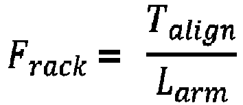
- It is noted that, of course, the rack and pinion mechanism is only an example and may be replaced by any other suitable mechanism such as a belt mechanism.
- Moreover, a motion of the rack can be described by the following equation, wherein mrack is the mass of the rack, x is the position of the rack, R is the pinion gear radius and b is the steering column damping.

- Consequently, the counter moment can be written as follows:

- Thus, the torque necessary for balancing the self-aligning moment Talign is a function of the lateral force Fy at the steered wheel. If the lateral force Fy is reduced, also the self-aligning moment Talign is reduced.
- Considering torque vectoring, the motion of the vehicle can be described by the following formula, wherein the first formula is a balance of forces along the lateral direction. The mass of the vehicle is denoted mvehicle and the acceleration of the vehicle in the lateral direction is denoted ay. It is assumed that the vehicle has two axles and the lateral force at the front axle is denoted Ffy. The lateral force at the rear axle is denoted Fry. The second formula is a balance of moments, wherein lf designates the lever arm of the lateral force at the front axle and lr designates the lever arm of the lateral force at the rear axle. The moment resulting from torque vectoring is designated MTV.


- Since the torque vectoring moment MTV is generated by applying different torques to the driven wheels, it can be written as a function of a longitudinal force Fx,left being provided at the left wheel and a longitudinal force Fx,right being provided at the right wheel. A track width of the vehicle is denoted w.

- Consequently, the lateral forces at the front axle and the rear axle can be written as follows:


- Thus, the lateral force Ffy at the front axle and the lateral force Fry at the rear axle are functions of the moment MTV resulting from torque vectoring. It is noted that the force at the rear axle is increased if the torque vectoring moment MTV is increased. The force at the front axle is decreased if the torque vectoring moment MTV is increased.
- A decreased lateral force at the front axle means that only a smaller wheel angle and a smaller angular rate are needed. Thus the moment Tassist provided by the power assisted steering unit can be smaller. Consequently, the power assisted steering unit needs less power.
- The power consumption Passist of the power assisted steering unit can be described as follows, wherein x designates a position of the rack and R is again the pinion gear radius. The efficiency of the power assisted steering unit is denoted η. The power consumption Passist can also be written as a function of the current Iassist and the voltage Uassist used in the power assisted steering unit.

- The power consumption PPT of the powertrain can be written as a sum of the power consumption of all electric motors comprised by the powertrain. In this context, each power consumption of an electric motor can be written as the product of the corresponding motor current and the corresponding motor voltage. This is denoted below for the case of a drivetrain with four electric motors.


- Additionally, the power consumption of each of the electric motors can be written as a function of the corresponding wheel torque. This is done in the following for an electric motor i. The corresponding wheel torque is denoted Ti. The corresponding rotational speed is ni and the efficiency is ηi.

- Consequently, the minimization problem to be solved for determining the first wheel torque value T1 for the left output shaft and the second wheel torque value T2 for the right output shaft which minimize the total power consumption of the drive axle and the power assisted steering unit, can be written as follows:

- In a case in which four driven wheels are considered, the minimization problem is as follows. In this context, a third wheel torque T3 for a second left output shaft and a fourth wheel torque T4 for a second right output shaft need to be determined.

- The minimization problem is subject to the condition that the total longitudinal force target value Fx,req is met. This can be written as follows, wherein rwheel is the effective wheel radius and n is the gear ratio of the electric motors. For the ease of representation, the condition is denoted for the case of four driven wheels. The letter i denotes a counter for the wheels.

- Moreover, the minimization problem is subject to the condition that the total lateral force target value Fy,req is met. In other words the cornering demand needs to be met. Again, the condition is denoted for the case of four driven wheels for the ease of representation. The letter i denotes a counter for the wheels.
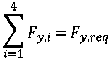
- Additionally, the yaw dynamics of the vehicles need to be balanced. This means that the total yaw moment target value Mz,req needs to be met. This is an additional condition to which the solution of the minimization problem is subject. As before, the condition is denoted for the case of four driven wheels, wherein the wheels and the corresponding forces and torques are numbered from one to four.

- The minimization problem as outline above may for example be solved by a quadratic nonlinear programming solver. Such a solver is for example provided in the quadprog toolbox in Matlab. Alternatively or additionally, an ACADO (Automatic Control And Dynamic Optimization) toolkit can be used. A further alternative is a so-called IPOPT (interior Point Optimizer) algorithm. Also Sequential Quadratic Programming (SQP) may be used to solve the minimization problem.
- Thus, the wheel torque values are determined and provided to the relevant parts of the vehicle such that an overall power consumption is reduced while the desired driving behavior of the vehicle is maintained.
- According to an example, the method further comprises providing a formula or a look-up table of the total power consumption of the drive axle and the power assisted steering unit as a function of the first wheel torque value and the second wheel torque value. Consequently, the determination of the first wheel torque for the left output shaft and the second wheel torque for the right output shaft of the drive axle which minimize the total power consumption is facilitated. Moreover, using a formula or a look-up table is computationally efficient. If a formula is used, it can be derived from the formulae as explained above. In a case in which a look-up table is used, the look-up table can be generated in a test environment, where the total power consumption of the drive axle and the power assisted steering unit is measured while different first wheel torques and different second wheel torques are applied.
- In an example, the method further comprises determining the first wheel torque value and the second wheel torque value under the condition that a rear lateral force is equal or below a rear lateral force threshold. Consequently, oversteering of the vehicle is avoided. This enhances driving safety
- According to an example, the method further comprises deactivating the propulsion torque distribution unit if the rear lateral force exceeds a rear lateral force deactivation threshold. This means that no torque vectoring is applied. Consequently, the same torque is applied on both the left output shaft and the right output shaft, i.e. the first wheel torque and the second wheel torque are of the same magnitude. Also this measure avoids oversteering of the vehicle and thus increases driving safety. In this context, the rear lateral force deactivation threshold may be the same as the rear lateral force threshold as mentioned above.
- In an example, the method further comprises deactivating the propulsion torque distribution unit if a rear side slip exceeds a rear side slip threshold. Again, deactivating the propulsion torque distribution unit means that no torque vectoring is applied, i.e. the same torque is provided at the left output shaft and the right output shaft. This enhances driving safety.
- The method may be at least partly computer-implemented, and may be implemented in software or in hardware, or in software and hardware. Further, the method may be carried out by computer program instructions running on means that provide data processing functions. The data processing means may be a suitable computing means, such as an electronic control module etc., which may also be a distributed computer system. The data processing means or the computer, respectively, may comprise one or more of a processor, a memory, a data interface, or the like.
- According to a second aspect, there is provided a data processing apparatus comprising a first communication interface configured to receive a total longitudinal force target value, a total lateral force target value, and a total yaw moment target value. Moreover, the data processing apparatus comprises a second communication interface configured to provide at least a first wheel torque value and a second wheel torque value to a drive axle. Furthermore, the data processing apparatus comprises means for carrying out the method of the present disclosure. Using such a data processing apparatus, the first wheel torque value and the second wheel torque value may be determined such that a total power consumption of the drive axle and the power assisted steering unit is minimized. Thus, an overall power consumption of the vehicle is reduced. This leads to an increased driving range of the vehicle. In other words, the energy efficiency of the vehicle is increased.
- The first wheel torque value and the second wheel torque value may be provided to the drive axle via the propulsion torque distribution unit.
- Again, the total longitudinal force target value, the total lateral force target value and the total yaw moment target value may be provided by a known driver interpreter unit which determines the total longitudinal force target value, the total lateral force target value and the total yaw moment target value based on a brake pedal position, an accelerator pedal positon, a steering angle and a steering torque. The driver interpreter unit may be communicatively connected to the data processing apparatus via the first communication interface.
- According to a third aspect, there is provided a computer program comprising instructions which, when the computer program is executed by a computer, cause the computer to carry out the method according to the present disclosure. Using such a computer program, the overall power consumption of the vehicle is reduced. Consequently, a driving range is increased.
- According to a fourth aspect, there is provided a computer-readable storage medium comprising instructions which, when executed by a computer, cause the computer to carry out the method according to the present disclosure. Thus, also the computer-readable storage medium leads to a reduced overall power consumption of the vehicle. This leads to an increased driving range.
- According to a fifth aspect, there is provided a vehicle propulsion system comprising an electric powertrain having at least one drive axle with a left output shaft and a right output shaft. Moreover, the vehicle propulsion system comprises a power assisted steering unit, a propulsion torque distribution unit being configured to allocate wheel torques of different magnitudes to the left output shaft and the right output shaft respectively, and a data processing apparatus according to the present disclosure. The data processing apparatus is communicatively coupled to the power assisted steering unit and the propulsion torque distribution unit. Thus, in such a vehicle propulsion system, the first wheel torque value and the second wheel torque value may be determined such that a total power consumption of the drive axle and the power assisted steering unit is minimized. Thus, an overall power consumption of the vehicle is reduced. This leads to an increased driving range of the vehicle. In other words, the energy efficiency of the vehicle is increased.
- It is noted that the data processing apparatus may be communicatively coupled to the drive axle via the propulsion torque distribution unit.
- In an example, a wheel may be mounted to each of the output shafts.
- In an example, the drive axle comprises a left electric machine being coupled to the left output shaft and a right electric machine being coupled to the right output shaft. Consequently, a wheel torque may be provided at each of the left output shaft and the right output shaft with high precision and reliability. Moreover, the torques provided by the left electric machine and the right electric machine are generally independent from one another. A gearing unit may be interposed between each electric machine and the corresponding output shaft. The power consumption of the drive axle is, thus, the sum of the power consumption of the left electric machine and the right electric machine.
- In an example, the vehicle propulsion system further comprises a rear side slip detector for determining a rear side slip of the vehicle. The rear side slip detector may be realized as a so-called inertial measurement unit. Thus, rear side slip can be detected with high precision and high reliability. The vehicle can be controlled such that rear side slip does not occur or only to a pre-defined extent. Consequently, the vehicle has a safe driving behavior.
- It should be noted that the above examples may be combined with each other irrespective of the aspect involved. Accordingly, the method may be combined with structural features and, likewise, the data processing apparatus, the computer program, the computer-readable storage medium and the vehicle propulsion system may be combined with features described above with regard to the method.
- These and other aspects of the present disclosure will become apparent from and elucidated with reference to the examples described hereinafter.
- Examples of the present disclosure will be described in the following with reference to the following drawings.
- Figure 1
- schematically shows a vehicle having a vehicle propulsion system according to the present disclosure with a data processing apparatus according to the present disclosure having thereon a computer-readable storage medium according to the present disclosure and a computer program according to the present disclosure, wherein the data processing apparatus is configured to carry out a method according to the present disclosure, and
- Figure 2
- shows steps of the method according to the present disclosure.
- The figures are merely schematic representations and serve only to illustrate examples of the disclosure. Identical or equivalent elements are in principle provided with the same reference signs.
-
Figure 1 shows avehicle 10 having apropulsion system 12. - The
propulsion system 12 comprises anelectric powertrain 14. - In the example shown in the figure, the
electric powertrain 14 comprises twodrive axles - The
drive axle 16 is a front drive axle and thedrive axle 18 is a rear drive axle. - On the
drive axle 16 twofront wheels - On the
drive axle 18, tworear wheels - The
drive axle 16 comprises a leftelectric machine 28 and a rightelectric machine 30. The leftelectric machine 28 is coupled tofront wheel 20 via aleft output shaft 32 and the rightelectric machine 30 is coupled to theright front wheel 22 via aright output shaft 34. - The
drive axle 18 comprises a leftelectric machine 36 and a rightelectric machine 38. The leftelectric machine 36 is coupled torear wheel 24 via aleft output shaft 40 and the rightelectric machine 38 is coupled to the rightrear wheel 26 via aright output shaft 42. - All
electric machines torque distribution unit 44. - The propulsion
torque distribution unit 44 is configured to allocate wheel torques of different magnitudes to theoutput shafts electric machines electric machines respective output shaft - In simplified words, the
torque distribution unit 44 may be called an electric motor control unit which is able to provide a torque vectoring functionality. Consequently, the propulsion torque distribution unit may also be called a torque vectoring unit or an active yaw unit. - Moreover, the
vehicle propulsion system 12 comprises a power assisted steering unit 46. - The power assisted steering unit 46 comprises a
steering actuator 48 with an electric machine having a shaft with apinion 50. Thepinion 50 engages arack 52 of a steering system of thevehicle 10 such that thesteering actuator 48, more generally speaking the assisted steering unit 46, can move therack 52 either with or without an additional force being provided on therack 52 by a user acting on asteering wheel 54 of thevehicle 10. - The
vehicle propulsion system 12 also comprises a data processing apparatus 56. - The data processing apparatus 56 comprises a first communication interface 58.
- The first communication interface 58 is communicatively connected to a
driver interpreter unit 60. - The
driver interpreter unit 60 is configured to provide a total longitudinal force target value, a total lateral force target value, and a total yaw moment value based on a brake pedal position, an accelerator pedal positon, a steering angle and a steering torque. - The first communication interface 58 is configured to receive the total longitudinal force target value, the total lateral force target value, and the total yaw moment value.
- The data processing apparatus 56 also comprises a
second communication interface 62 which is communicatively connected to the propulsiontorque distribution unit 44. - The
second communication interface 62 is configured to provide a first wheel torque value, a second wheel torque value, a third wheel torque value and a fourth wheel torque value to the propulsiontorque distribution unit 44. Since the propulsiontorque distribution unit 44 is communicatively connected to thedrive axles electric machines drive axles electric machines - Additionally, the data processing apparatus 56 has a third communication interface 64.
- The third communication interface 64 is communicatively connected to the power assisted steering unit 46, more precisely to the
actuator 48. - Moreover, the data processing apparatus 56 has a
fourth communication interface 66. A rearside slip detector 68 is connected to the data processing apparatus 56 via thefourth communication interface 66. - The rear
side slip detector 68 is configured to for determine a rear side slip of thevehicle 10. - It is noted that even though the data processing apparatus 56, the propulsion
torque distribution unit 44 and thedriver interpreter unit 60 are represented as separate units, one or more of these units may be integrated into a single unit. For example, the data processing apparatus 56 and the propulsiontorque distribution unit 44 may be united in a single unit. - The data processing apparatus 56 comprises a data storage unit 70 and a data processing unit 72.
- The data processing apparatus 56 is configured to carry out a method for controlling a motion of the
vehicle 10. - In more detail, the data storage unit 70 and the data processing unit 72 form means 74 for carrying out the method for controlling a motion of the
vehicle 10. - To this end, the data storage unit 70 comprises a computer-readable storage medium 76 comprising instructions which, when executed by the data processing unit 72 or more generally a computer, cause the data processing unit 72 to carry out the method.
- Thus, a computer program 78 is provided by the data storage unit 76.
- The computer program 78 comprises instructions which, when the computer program 78 is executed by the data processing unit 72 or more generally a computer, cause the data processing unit 72 to carry out the method.
- The method for controlling a motion of the
vehicle 10 will now be explained in connection withFigure 2 . - A first step S1 of the method comprises receiving a total longitudinal force target value, a total lateral force target value and a total yaw moment target value. As has already been explained above, these parameters are provided to the data processing unit 56 by the
driver interpreter unit 60 via the first communication interface 58. - In a second step S2 a first wheel torque value for the
left output shaft 32 of thedrive axle 16, a second wheel torque value for theright output shaft 34 of thedrive axle 16, a third wheel torque value for theleft output shaft 40 of thedrive axle 18, and a fourth wheel torque value for theright output shaft 42 of thedrive axle 18 are determined. - The wheel torque values are determined such that they minimize a total power consumption of the
drive axles - To this end, a set 80 of formulae as has already been described above or a look-up table 82 of the total power consumption of the
drive axles - A condition to be met by the minimization is that the total longitudinal force target value, the total lateral force target value and the total yaw moment target value are met. Put otherwise, the minimization of the total power consumption must not influence the driving behavior required by the driver.
- A further condition is that a rear lateral force of the
vehicle 10 is equal or below a rear lateral force threshold. Thus, the wheel torque values must be determined such that thevehicle 10 does not oversteer. - The determined first wheel torque value, the second wheel torque value, the third wheel torque value and the fourth wheel torque value are then provided to the
drive axles torque distribution unit 44. - While driving, the rear
side slip detector 68 is active and constantly or periodically monitors a rear side slip of thevehicle 10 and communicates the detected rear side slip to the data processing apparatus 56. - On the data storage unit 70 a rear side slip threshold is provided.
- The data processing apparatus 56 is configured to periodically compare the detected rear side slip and the rear side slip threshold.
- If it is found that the detected rear side slip exceeds the rear side slip threshold, the propulsion
torque distribution unit 44 is deactivated. This means that the same torque is provided to each of theoutput shafts - It is noted that in an alternative, the propulsion
torque distribution unit 44 may also be deactivated, if the rear lateral force exceeds a rear lateral force deactivation threshold. - Other variations to the disclosed examples can be understood and effected by those skilled in the art in practicing the claimed disclosure, from the study of the drawings, the disclosure, and the appended claims. In the claims the word "comprising" does not exclude other elements or steps and the indefinite article "a" or "an" does not exclude a plurality. A single processor or other unit may fulfill the functions of several items or steps recited in the claims. The mere fact that certain measures are recited in mutually different dependent claims does not indicate that a combination of these measures cannot be used to advantage. A computer program may be stored/distributed on a suitable medium such as an optical storage medium or a solid-state medium supplied together with or as part of other hardware, but may also be distributed in other forms, such as via the Internet or other wired or wireless telecommunication systems. Any reference signs in the claims should not be construed as limiting the scope of the claims.
-
- 10
- vehicle
- 12
- propulsion system
- 14
- powertrain
- 16
- drive axle
- 18
- drive axle
- 20
- front wheel
- 22
- front wheel
- 24
- rear wheel
- 26
- rear wheel
- 28
- left electric machine
- 30
- right electric machine
- 32
- left output shaft
- 34
- right output shaft
- 36
- left electric machine
- 38
- right electric machine
- 40
- left output shaft
- 42
- right output shaft
- 44
- propulsion torque distribution unit
- 46
- power assisted steering unit
- 48
- steering actuator
- 50
- pinion
- 52
- rack
- 54
- steering wheel
- 56
- data processing apparatus
- 58
- first communication interface
- 60
- driver interpreter unit
- 62
- second communication interface
- 64
- third communication interface
- 66
- fourth communication interface.
- 68
- rear side slip detector
- 70
- data storage unit
- 72
- data processing unit
- 74
- means to carry out the method for controlling a motion of a vehicle
- 76
- computer-readable storage medium
- 78
- computer program
- 80
- set of formulae
- 82
- look-up table
- S1
- first step
- S2
- second step
- S3
- third step
Claims (11)
- A method for controlling a motion of a vehicle (10), wherein the vehicle (10) comprises an electric powertrain (14) having at least one drive axle (16, 18) with a left output shaft (32, 40) and a right output shaft (34, 42), a power assisted steering unit (46) and a propulsion torque distribution unit (44), the propulsion torque distribution unit (44) being configured to allocate wheel torques of different magnitudes to the left output shaft (32, 40) and the right output shaft (34, 42) respectively, the method comprising:- receiving a total longitudinal force target value, a total lateral force target value and a total yaw moment target value,- determining a first wheel torque value for the left output shaft (32, 40) and a second wheel torque value for the right output shaft (34, 42) which minimize a total power consumption of the drive axle (16, 18) and the power assisted steering unit (46) under the condition that the total longitudinal force target value, the total lateral force target value and the total yaw moment target value are met,- providing the determined first wheel torque value and the determined second wheel torque value to the drive axle (16, 18).
- The method of claim 1, further comprising: providing a formula (80) or a look-up table (82) of the total power consumption of the drive axle (16, 18) and the power assisted steering unit (46) as a function of the first wheel torque and the second wheel torque.
- The method of any one of the preceding claims, further comprising: determining the first wheel torque value and the second wheel torque value under the condition that a rear lateral force is equal or below a rear lateral force threshold.
- The method of any one of the preceding claims, further comprising: deactivating the propulsion torque distribution unit (44) if the rear lateral force exceeds a rear lateral force deactivation threshold.
- The method of any one of the preceding claims, further comprising: deactivating the propulsion torque distribution unit (44) if a rear side slip exceeds a rear side slip threshold.
- A data processing apparatus (56) comprising a first communication interface (58) configured to receive a total longitudinal force target value, a total lateral force target value, and a total yaw moment target value, a second communication interface (62) configured to provide at least a first wheel torque value and a second wheel torque value to a drive axle (16, 18), and means (74) for carrying out the method of any one of the preceding claims.
- A computer program (78) comprising instructions which, when the computer program (78) is executed by a computer, cause the computer to carry out the method of any one of claims 1 to 5.
- A computer-readable storage medium (76) comprising instructions which, when executed by a computer, cause the computer to carry out the method of any one of claims 1 to 5.
- A vehicle propulsion system (12) comprisingan electric powertrain (14) having at least one drive axle (16, 18) with a left output shaft (32, 40) and a right output shaft (34, 42),a power assisted steering unit (42),a propulsion torque distribution unit (44) being configured to allocate wheel torques of different magnitudes to the left output shaft (32, 40) and the right output shaft (34, 42) respectively, anda data processing apparatus (56) according to claim 6,wherein the data processing apparatus (56) is communicatively coupled to the power assisted steering unit (46) and the propulsion torque distribution unit (44).
- The vehicle propulsion system (12) of claim 9, wherein the drive axle (16, 18) comprises a left electric machine (28, 36), being coupled to the left output shaft (32, 40) and a right electric machine (30, 38) being coupled to the right output shaft (34, 42).
- The vehicle propulsion system (12) of claim 9 or 10, further comprising a rear side slip detector (68) for determining a rear side slip of the vehicle (10).
Priority Applications (2)
| Application Number | Priority Date | Filing Date | Title |
|---|---|---|---|
| EP22168077.0A EP4261091A1 (en) | 2022-04-13 | 2022-04-13 | Method for controlling a motion of a vehicle, data processing apparatus, computer program, computer-readable storage medium, and vehicle propulsion system |
| US18/299,233 US12351039B2 (en) | 2022-04-13 | 2023-04-12 | Method for controlling a motion of a vehicle, data processing apparatus, computer program, computer-readable storage medium, and vehicle propulsion system |
Applications Claiming Priority (1)
| Application Number | Priority Date | Filing Date | Title |
|---|---|---|---|
| EP22168077.0A EP4261091A1 (en) | 2022-04-13 | 2022-04-13 | Method for controlling a motion of a vehicle, data processing apparatus, computer program, computer-readable storage medium, and vehicle propulsion system |
Publications (1)
| Publication Number | Publication Date |
|---|---|
| EP4261091A1 true EP4261091A1 (en) | 2023-10-18 |
Family
ID=81581262
Family Applications (1)
| Application Number | Title | Priority Date | Filing Date |
|---|---|---|---|
| EP22168077.0A Pending EP4261091A1 (en) | 2022-04-13 | 2022-04-13 | Method for controlling a motion of a vehicle, data processing apparatus, computer program, computer-readable storage medium, and vehicle propulsion system |
Country Status (2)
| Country | Link |
|---|---|
| US (1) | US12351039B2 (en) |
| EP (1) | EP4261091A1 (en) |
Cited By (1)
| Publication number | Priority date | Publication date | Assignee | Title |
|---|---|---|---|---|
| WO2025113020A1 (en) * | 2023-11-29 | 2025-06-05 | 长城汽车股份有限公司 | Vehicle control method, vehicle and computer-readable storage medium |
Citations (3)
| Publication number | Priority date | Publication date | Assignee | Title |
|---|---|---|---|---|
| US20170210414A1 (en) * | 2016-01-26 | 2017-07-27 | Fuji Jukogyo Kabushiki Kaisha | Control unit for vehicle and control method for vehicle |
| US10899340B1 (en) * | 2017-06-21 | 2021-01-26 | Apple Inc. | Vehicle with automated subsystems |
| WO2022042818A1 (en) * | 2020-08-24 | 2022-03-03 | Volvo Truck Corporation | A method for controlling steering of a vehicle arrangement |
Family Cites Families (3)
| Publication number | Priority date | Publication date | Assignee | Title |
|---|---|---|---|---|
| US9199526B2 (en) * | 2013-02-26 | 2015-12-01 | Jtekt Corporation | Vehicle and vehicle driving device |
| KR102494255B1 (en) * | 2016-01-04 | 2023-02-03 | 에이치엘만도 주식회사 | Steering Arbitration Apparatus and Method of Vehicle, and Steering Arbitration System having the same |
| US20220258723A1 (en) * | 2021-02-15 | 2022-08-18 | GM Global Technology Operations LLC | Motion and torque control architecture for mobile platform having distributed torque actuators |
-
2022
- 2022-04-13 EP EP22168077.0A patent/EP4261091A1/en active Pending
-
2023
- 2023-04-12 US US18/299,233 patent/US12351039B2/en active Active
Patent Citations (3)
| Publication number | Priority date | Publication date | Assignee | Title |
|---|---|---|---|---|
| US20170210414A1 (en) * | 2016-01-26 | 2017-07-27 | Fuji Jukogyo Kabushiki Kaisha | Control unit for vehicle and control method for vehicle |
| US10899340B1 (en) * | 2017-06-21 | 2021-01-26 | Apple Inc. | Vehicle with automated subsystems |
| WO2022042818A1 (en) * | 2020-08-24 | 2022-03-03 | Volvo Truck Corporation | A method for controlling steering of a vehicle arrangement |
Non-Patent Citations (1)
| Title |
|---|
| KOEHLER STEFAN ET AL: "Energy-Efficiency Optimization of Torque Vectoring Control for Battery Electric Vehicles", IEEE INTELLIGENT TRANSPORTATION SYSTEMS MAGAZINE, IEEE, USA, vol. 9, no. 3, 1 October 2017 (2017-10-01), pages 59 - 74, XP011660611, ISSN: 1939-1390, [retrieved on 20170725], DOI: 10.1109/MITS.2017.2709799 * |
Cited By (1)
| Publication number | Priority date | Publication date | Assignee | Title |
|---|---|---|---|---|
| WO2025113020A1 (en) * | 2023-11-29 | 2025-06-05 | 长城汽车股份有限公司 | Vehicle control method, vehicle and computer-readable storage medium |
Also Published As
| Publication number | Publication date |
|---|---|
| US12351039B2 (en) | 2025-07-08 |
| US20230331097A1 (en) | 2023-10-19 |
Similar Documents
| Publication | Publication Date | Title |
|---|---|---|
| EP4253181B1 (en) | Vehicle front and rear drive torque distribution method and apparatus, and vehicle | |
| US10427669B2 (en) | Method and apparatus for controlling distribution of front and rear wheel torque of four-wheel drive vehicle | |
| CN102275580B (en) | Power actuated vehicle and control method thereof | |
| KR101083946B1 (en) | Vehicle drive apparatus | |
| US8670905B2 (en) | Vehicle stability control method and system | |
| JP2004104991A (en) | Control method and system for independent braking and controllability of vehicle with regenerative braking | |
| US11541876B2 (en) | Electronic stability control method for vehicle | |
| EP4382346A1 (en) | Vehicle control device | |
| CN116620398B (en) | Vehicle control methods, devices, equipment and storage media | |
| EP3103702A1 (en) | Vehicle control device of four-wheel independent drive vehicle for when one wheel is lost | |
| US20040199316A1 (en) | Vehicle motion control method and vehicle motion control apparatus | |
| WO2006093241A1 (en) | Braking-driving force control device of vehicle | |
| CN119283841B (en) | Running stability control method for distributed wheel-side driving heavy tractor | |
| US12187285B2 (en) | Torque vectoring system, method and associated vehicle | |
| CN101844583A (en) | Vehicle double steering control method | |
| US12351039B2 (en) | Method for controlling a motion of a vehicle, data processing apparatus, computer program, computer-readable storage medium, and vehicle propulsion system | |
| US12371004B2 (en) | Driving/braking force control apparatus | |
| JP2017100504A (en) | Vehicle control apparatus and vehicle control method | |
| JPH10271613A (en) | Drive control device for electric vehicles | |
| JP2017109558A (en) | Vehicle turning control device | |
| US9592825B2 (en) | Vehicle control system | |
| EP4574534A1 (en) | Vehicle control device and vehicle control method | |
| Berbar et al. | A Matlab/Simulink model for Electric vehicle with four independent in-wheel Drive and steering | |
| CN116157294B (en) | Vehicle control device | |
| US12441195B2 (en) | Control device for vehicle |
Legal Events
| Date | Code | Title | Description |
|---|---|---|---|
| PUAI | Public reference made under article 153(3) epc to a published international application that has entered the european phase |
Free format text: ORIGINAL CODE: 0009012 |
|
| STAA | Information on the status of an ep patent application or granted ep patent |
Free format text: STATUS: REQUEST FOR EXAMINATION WAS MADE |
|
| 17P | Request for examination filed |
Effective date: 20221216 |
|
| AK | Designated contracting states |
Kind code of ref document: A1 Designated state(s): AL AT BE BG CH CY CZ DE DK EE ES FI FR GB GR HR HU IE IS IT LI LT LU LV MC MK MT NL NO PL PT RO RS SE SI SK SM TR |
|
| STAA | Information on the status of an ep patent application or granted ep patent |
Free format text: STATUS: EXAMINATION IS IN PROGRESS |
|
| 17Q | First examination report despatched |
Effective date: 20240703 |