EP4261061A1 - Method to control an active shock absorber of a road vehicle - Google Patents
Method to control an active shock absorber of a road vehicle Download PDFInfo
- Publication number
- EP4261061A1 EP4261061A1 EP23167686.7A EP23167686A EP4261061A1 EP 4261061 A1 EP4261061 A1 EP 4261061A1 EP 23167686 A EP23167686 A EP 23167686A EP 4261061 A1 EP4261061 A1 EP 4261061A1
- Authority
- EP
- European Patent Office
- Prior art keywords
- shock absorber
- active shock
- elements
- control method
- transfer function
- Prior art date
- Legal status (The legal status is an assumption and is not a legal conclusion. Google has not performed a legal analysis and makes no representation as to the accuracy of the status listed.)
- Granted
Links
Images


Classifications
-
- B—PERFORMING OPERATIONS; TRANSPORTING
- B60—VEHICLES IN GENERAL
- B60G—VEHICLE SUSPENSION ARRANGEMENTS
- B60G17/00—Resilient suspensions having means for adjusting the spring or vibration-damper characteristics, for regulating the distance between a supporting surface and a sprung part of vehicle or for locking suspension during use to meet varying vehicular or surface conditions, e.g. due to speed or load
- B60G17/06—Characteristics of dampers, e.g. mechanical dampers
-
- B—PERFORMING OPERATIONS; TRANSPORTING
- B60—VEHICLES IN GENERAL
- B60G—VEHICLE SUSPENSION ARRANGEMENTS
- B60G17/00—Resilient suspensions having means for adjusting the spring or vibration-damper characteristics, for regulating the distance between a supporting surface and a sprung part of vehicle or for locking suspension during use to meet varying vehicular or surface conditions, e.g. due to speed or load
- B60G17/015—Resilient suspensions having means for adjusting the spring or vibration-damper characteristics, for regulating the distance between a supporting surface and a sprung part of vehicle or for locking suspension during use to meet varying vehicular or surface conditions, e.g. due to speed or load the regulating means comprising electric or electronic elements
-
- B—PERFORMING OPERATIONS; TRANSPORTING
- B60—VEHICLES IN GENERAL
- B60G—VEHICLE SUSPENSION ARRANGEMENTS
- B60G17/00—Resilient suspensions having means for adjusting the spring or vibration-damper characteristics, for regulating the distance between a supporting surface and a sprung part of vehicle or for locking suspension during use to meet varying vehicular or surface conditions, e.g. due to speed or load
- B60G17/015—Resilient suspensions having means for adjusting the spring or vibration-damper characteristics, for regulating the distance between a supporting surface and a sprung part of vehicle or for locking suspension during use to meet varying vehicular or surface conditions, e.g. due to speed or load the regulating means comprising electric or electronic elements
- B60G17/018—Resilient suspensions having means for adjusting the spring or vibration-damper characteristics, for regulating the distance between a supporting surface and a sprung part of vehicle or for locking suspension during use to meet varying vehicular or surface conditions, e.g. due to speed or load the regulating means comprising electric or electronic elements characterised by the use of a specific signal treatment or control method
- B60G17/0182—Resilient suspensions having means for adjusting the spring or vibration-damper characteristics, for regulating the distance between a supporting surface and a sprung part of vehicle or for locking suspension during use to meet varying vehicular or surface conditions, e.g. due to speed or load the regulating means comprising electric or electronic elements characterised by the use of a specific signal treatment or control method involving parameter estimation, e.g. observer, Kalman filter
-
- B—PERFORMING OPERATIONS; TRANSPORTING
- B60—VEHICLES IN GENERAL
- B60G—VEHICLE SUSPENSION ARRANGEMENTS
- B60G13/00—Resilient suspensions characterised by arrangement, location or type of vibration dampers
- B60G13/001—Arrangements for attachment of dampers
- B60G13/005—Arrangements for attachment of dampers characterised by the mounting on the axle or suspension arm of the damper unit
-
- B—PERFORMING OPERATIONS; TRANSPORTING
- B60—VEHICLES IN GENERAL
- B60G—VEHICLE SUSPENSION ARRANGEMENTS
- B60G17/00—Resilient suspensions having means for adjusting the spring or vibration-damper characteristics, for regulating the distance between a supporting surface and a sprung part of vehicle or for locking suspension during use to meet varying vehicular or surface conditions, e.g. due to speed or load
- B60G17/015—Resilient suspensions having means for adjusting the spring or vibration-damper characteristics, for regulating the distance between a supporting surface and a sprung part of vehicle or for locking suspension during use to meet varying vehicular or surface conditions, e.g. due to speed or load the regulating means comprising electric or electronic elements
- B60G17/0152—Resilient suspensions having means for adjusting the spring or vibration-damper characteristics, for regulating the distance between a supporting surface and a sprung part of vehicle or for locking suspension during use to meet varying vehicular or surface conditions, e.g. due to speed or load the regulating means comprising electric or electronic elements characterised by the action on a particular type of suspension unit
-
- B—PERFORMING OPERATIONS; TRANSPORTING
- B60—VEHICLES IN GENERAL
- B60G—VEHICLE SUSPENSION ARRANGEMENTS
- B60G17/00—Resilient suspensions having means for adjusting the spring or vibration-damper characteristics, for regulating the distance between a supporting surface and a sprung part of vehicle or for locking suspension during use to meet varying vehicular or surface conditions, e.g. due to speed or load
- B60G17/015—Resilient suspensions having means for adjusting the spring or vibration-damper characteristics, for regulating the distance between a supporting surface and a sprung part of vehicle or for locking suspension during use to meet varying vehicular or surface conditions, e.g. due to speed or load the regulating means comprising electric or electronic elements
- B60G17/019—Resilient suspensions having means for adjusting the spring or vibration-damper characteristics, for regulating the distance between a supporting surface and a sprung part of vehicle or for locking suspension during use to meet varying vehicular or surface conditions, e.g. due to speed or load the regulating means comprising electric or electronic elements characterised by the type of sensor or the arrangement thereof
-
- B—PERFORMING OPERATIONS; TRANSPORTING
- B60—VEHICLES IN GENERAL
- B60G—VEHICLE SUSPENSION ARRANGEMENTS
- B60G2202/00—Indexing codes relating to the type of spring, damper or actuator
- B60G2202/40—Type of actuator
- B60G2202/42—Electric actuator
-
- B—PERFORMING OPERATIONS; TRANSPORTING
- B60—VEHICLES IN GENERAL
- B60G—VEHICLE SUSPENSION ARRANGEMENTS
- B60G2400/00—Indexing codes relating to detected, measured or calculated conditions or factors
- B60G2400/10—Acceleration; Deceleration
- B60G2400/102—Acceleration; Deceleration vertical
-
- B—PERFORMING OPERATIONS; TRANSPORTING
- B60—VEHICLES IN GENERAL
- B60G—VEHICLE SUSPENSION ARRANGEMENTS
- B60G2400/00—Indexing codes relating to detected, measured or calculated conditions or factors
- B60G2400/20—Speed
- B60G2400/202—Piston speed; Relative velocity between vehicle body and wheel
-
- B—PERFORMING OPERATIONS; TRANSPORTING
- B60—VEHICLES IN GENERAL
- B60G—VEHICLE SUSPENSION ARRANGEMENTS
- B60G2400/00—Indexing codes relating to detected, measured or calculated conditions or factors
- B60G2400/25—Stroke; Height; Displacement
- B60G2400/252—Stroke; Height; Displacement vertical
-
- B—PERFORMING OPERATIONS; TRANSPORTING
- B60—VEHICLES IN GENERAL
- B60G—VEHICLE SUSPENSION ARRANGEMENTS
- B60G2500/00—Indexing codes relating to the regulated action or device
- B60G2500/10—Damping action or damper
-
- B—PERFORMING OPERATIONS; TRANSPORTING
- B60—VEHICLES IN GENERAL
- B60G—VEHICLE SUSPENSION ARRANGEMENTS
- B60G2600/00—Indexing codes relating to particular elements, systems or processes used on suspension systems or suspension control systems
- B60G2600/18—Automatic control means
- B60G2600/182—Active control means
-
- B—PERFORMING OPERATIONS; TRANSPORTING
- B60—VEHICLES IN GENERAL
- B60G—VEHICLE SUSPENSION ARRANGEMENTS
- B60G2600/00—Indexing codes relating to particular elements, systems or processes used on suspension systems or suspension control systems
- B60G2600/18—Automatic control means
- B60G2600/187—Digital Controller Details and Signal Treatment
-
- B—PERFORMING OPERATIONS; TRANSPORTING
- B60—VEHICLES IN GENERAL
- B60G—VEHICLE SUSPENSION ARRANGEMENTS
- B60G2600/00—Indexing codes relating to particular elements, systems or processes used on suspension systems or suspension control systems
- B60G2600/70—Computer memory; Data storage, e.g. maps for adaptive control
-
- B—PERFORMING OPERATIONS; TRANSPORTING
- B60—VEHICLES IN GENERAL
- B60G—VEHICLE SUSPENSION ARRANGEMENTS
- B60G2800/00—Indexing codes relating to the type of movement or to the condition of the vehicle and to the end result to be achieved by the control action
- B60G2800/70—Estimating or calculating vehicle parameters or state variables
Definitions
- the invention relates to a method to control an active shock absorber of a road vehicle.
- passive shock absorbers are entirely determined by the stresses transmitted by the road surface and, therefore, passive shock absorbers are "at the mercy" of the road surface.
- active shock absorbers have been offered, which are capable of making autonomous movements (namely, completely independent of the stresses transmitted by the road surface), which are added to the movements caused by the stresses transmitted by the road surface; the aim of the autonomous movements made by an active shock absorber is that of reacting to the stresses transmitted by the road surface so as to maximize the dynamic performance of the road vehicle or improve the driving comfort of the road vehicle (the same road vehicle can have its active shock absorbers pursue different targets depending on the type of driving chosen by the driver).
- An active shock absorber is provided with a hydraulic or electric shock absorber of its own, which can be controlled so as to generate an autonomous movement (namely, completely independent of the stresses transmitted by the road surface).
- Patent application US2018134111A1 discloses a method to control the active shock absorbers of a car.
- the object of the invention is to provide a method to control an active shock absorber of a road vehicle, which is capable of optimizing the damping response.
- reference number 1 indicates, as a whole, a road vehicle provided with two front wheels 2 and with two rear wheels 2.
- the road vehicle 1 is provided with a powertrain system (which is known and is not shown herein), which can comprise an internal combustion engine and/or one or more electric motors and can transmit a motion to the front wheels 2 and/or to the rear wheels 2.
- a powertrain system (which is known and is not shown herein), which can comprise an internal combustion engine and/or one or more electric motors and can transmit a motion to the front wheels 2 and/or to the rear wheels 2.
- a hub 3 (schematically shown in figure 2 ) of each wheel 2 is connected to a frame 4 of the road vehicle 1 by means of a suspension 5 (partially shown in figure 1 ), which is provided with an (electronically controlled) active shock absorber 6, which is capable of making autonomous movements (namely, completely independent of the stresses transmitted by the road surface), which are added to the movements caused by the stresses transmitted by the road surface.
- each active shock absorber 6 comprises an element 7, which defines an end of the active shock absorber 6, and an element 8, which defines the other end of the active shock absorber 6 and is mounted so as to slide relative to the element 7 in order to be able to linearly translate relative to the element 7.
- Each active shock absorber 6 comprises a spring 9, which is connected between the two elements 7 and 8 and is compressed or expanded when the two elements 7 and 8 linearly translate relative to one another.
- each active shock absorber 6 comprises an electric actuator 10 (typically, a rotary electric motor), which is configured to have the active shock absorber 6 make autonomous movements (namely, completely independent of the stresses transmitted by the road surface) between the elements 7 and 8, namely is capable of generating a force F, which is applied between the elements 7 and 8.
- the active shock absorbers 6 could be of the type described in patent applications US2008190104A1 and WO2014145215A2 .
- Each active shock absorber 6 comprises a position sensor 11 (for example, a potentiometer), which provides the relative position p of the two elements 7 and 8, namely the exact measure of how much the element 8 is translated relative to the element 7. Furthermore, each active shock absorber 6 comprises a position sensor 11 (for example, a rotary encoder), which provides the angular position ⁇ of the electric actuator 10.
- the road vehicle 1 comprises four vertical accelerometers 13, which are mounted on the hubs 3 of the wheels 2, namely are rigidly fixed to the hubs 3 of the wheels 2 in order to move with the hubs 3 of the wheels 2 in an integral manner. Each vertical accelerometer 13 is configured to measure a vertical acceleration a z of the corresponding hub 3.
- the road vehicle 1 comprises a longitudinal accelerometer 14 and a transverse accelerometer 15, which are mounted on the frame 4, namely are rigidly fixed to the frame 4 in order to move with the frame in an integral manner 4, and are configured to measure a longitudinal acceleration a x and a transverse acceleration a y of the frame 4 (namely, of the road vehicle 1), respectively.
- the two accelerometers 14 and 15 could be integrated in one single sensor (for example, a triple-axis accelerometer), which provides both the longitudinal acceleration a x and the transverse acceleration a y .
- the road vehicle 1 comprises an electronic control unit ( "ECU” ) 16, which, among other things, controls the actuators 10 of the active shock absorbers 6 in the ways described below; from a physical point of view, the control unit 16 can consist of one single device or of several devices, which are separate from one another and communicate through the CAN network of the road vehicle 1.
- the control unit 16 is connected (directly or indirectly through a BUS network of the road vehicle 1) to the position sensors 11 and 12 and to the accelerometers 13, 14 and 15.
- the control unit 16 implements an estimating block 17, which determines (estimates) a speed v of translation between the two elements 7 and 8 of the active shock absorber 6.
- the estimating block 17 estimates the speed v of translation between the two elements 7 and 8 of the active shock absorber 6 based on a moving speed of the actuator 10 of the active shock absorber 6 (determined by deriving, in the time, the position p of the actuator 10 measured by the position sensor 12), based on the relative position p between the two elements 7 and 8 of the active shock absorber 6 (directly measured by the position sensor 11) and based on the vertical acceleration a z in the area of the hub 3 (directly measured by the vertical accelerometer 13).
- control unit 16 implements a control block 18, which, by using an open-loop transfer function TF 1 , determines a contribution C 1 exclusively based on the sole vertical acceleration a z in the area of the hub 3 (directly measured by the vertical accelerometer 13); in other words, the contribution C 1 exclusively depends on the sole vertical acceleration a z in the area of the hub 3.
- control unit 16 implements a control block 19, which, by using an open-loop transfer function TF 2 , determines a contribution C 2 exclusively based on the sole speed v of translation between the two elements 7 and 8 of the active shock absorber 6 (provided by the estimating block 17); in other words, the contribution C 2 exclusively depends on the sole speed v of translation between the two elements 7 and 8 of the active shock absorber 6.
- control unit 16 implements an adder block 20, which calculates the target force F TGT of the actuator 10 by only and exclusively adding the two contributions C 1 and C 2 (it should be pointed out that the two contributions C 1 and C 2 also have a sign and, therefore, their sum is calculated taking into account the sign) ; namely, the value of the target force F TGT of the actuator 10 is exclusively determined by the sum of the sole contributions C 1 and C 2 .
- the open-loop transfer function TF 2 entails the force F generated by the actuator 10 (namely, the contribution C 2 of the target force F TGT of the actuator 10) being substantially proportional to the speed v of translation between the two elements 7 and 8 of the active shock absorber 6; namely, it increases as the speed v of translation between the two elements 7 and 8 of the active shock absorber 6 increases.
- the gain of the transfer function TF 2 is measured in [Ns/m] as, by being multiplied by the speed v of translation (measured in [m/s]), it directly provides the contribution C 2 of the target force F TGT of the actuator 10 (measured in [N]).
- the contribution C 1 is determined based on the sole vertical acceleration a z of the hub 3 and using the open-loop transfer function TF 1 , which provides the contribution C 1 based on the vertical acceleration a z ; similarly, the contribution C 2 is determined based on the sole speed v of translation between the two elements 7 and 8 of the active shock absorber 6 and using the open-loop transfer function TF 2 , which provides the contribution C 2 based on the speed v of translation.
- the control unit 16 determines the target force F TGT based on the vertical acceleration a z of the hub 3 and based on the speed v of translation between the two elements 7 and 8 of the active shock absorber 6 by exclusively using open-loop transfer functions TF 1 and TF 2 .
- the contribution C 1 determined based on the vertical acceleration a z constitutes an inertia compensation
- the contribution C 2 determined based on the speed v of translation between the two elements 7 and 8 of the active shock absorber 6 constitutes a damping compensation
- the transfer functions TF 1 and TF 2 are variable as the frequency varies (generally, ranging from 0 to 50 Hz) and have a gain and a phase.
- control unit 16 determines the target force F TGT for the actuator 10 of the active shock absorber 6 based on the vertical acceleration a z of the hub 3 (directly measured by the vertical accelerometer 13) and based on the speed v of translation between the two elements 7 and 8 of the active shock absorber 6 (provided by the estimating block 17).
- the control unit 16 controls the actuator 10 of the active shock absorber 6 so as to pursue the target force F TGT ; according to a preferred embodiment, the target force F TGT determined by the control unit 16 only and exclusively based on the vertical acceleration a z of the hub 3 and on the speed v of translation between the two elements 7 and 8 of the active shock absorber 6 could be added to other target forces determined in other ways and so as to pursue other targets (as described, for instance, in Italian patent applications 102021000015170 and 102021000015182 ).
- the transfer function TF 2 consists of a map of experimentally determined points.
- an optimal and desired transfer function TF 2-OPT is established on paper in order to have an optimal and desired damping; subsequently, a measured transfer function TF 2-MSR is experimentally determined by using mechanical stresses of the suspension 5 and by always keeping the second contribution C 2 at zero, namely by always having the target force F TGT coincide with the sole first contribution C 1 .
- the transfer function TF 2-OPT is determined as difference between the optimal and desired transfer function TF 2-OPT and the measured transfer function TF 2-MSR .
- control method described above has different advantages.
- control method disclosed above optimizes the damping response of the active shock absorber 6 (both in terms of effectiveness of the response and in terms of promptness of the response), though maintaining a hood level of comfort.
- control method disclosed above is particularly stable and safe as, by operating in open loop, it never risks triggering undesired oscillations.
- control method described above is simple and economic to be implemented, for it does not require either a significant calculation ability or a large memory space.
Landscapes
- Engineering & Computer Science (AREA)
- Mechanical Engineering (AREA)
- Vehicle Body Suspensions (AREA)
Abstract
Description
- This patent application claims priority from
Italian patent application no. 102022000007496 filed on April 14, 2022 - The invention relates to a method to control an active shock absorber of a road vehicle.
- The movement of passive shock absorbers is entirely determined by the stresses transmitted by the road surface and, therefore, passive shock absorbers are "at the mercy" of the road surface. For a few years now, active shock absorbers have been offered, which are capable of making autonomous movements (namely, completely independent of the stresses transmitted by the road surface), which are added to the movements caused by the stresses transmitted by the road surface; the aim of the autonomous movements made by an active shock absorber is that of reacting to the stresses transmitted by the road surface so as to maximize the dynamic performance of the road vehicle or improve the driving comfort of the road vehicle (the same road vehicle can have its active shock absorbers pursue different targets depending on the type of driving chosen by the driver).
- An active shock absorber is provided with a hydraulic or electric shock absorber of its own, which can be controlled so as to generate an autonomous movement (namely, completely independent of the stresses transmitted by the road surface).
- Patent application
US2018134111A1 discloses a method to control the active shock absorbers of a car. - The object of the invention is to provide a method to control an active shock absorber of a road vehicle, which is capable of optimizing the damping response.
- According to the invention, there is provided a method to control an active shock absorber of a road vehicle according to the appended claims.
- The appended claims describe preferred embodiments of the invention and form an integral part of the description.
- The invention will now be described with reference to the accompanying drawings showing a non-limiting embodiment thereof, wherein:
-
figure 1 is a schematic plan view of a road vehicle provided with four active shock absorbers, which are controlled according to the invention; -
figure 2 is a schematic view of a suspension of the road vehicle offigure 1 ; -
figure 3 is a control diagram implemented in a control unit of the road vehicle offigure 1 ; and -
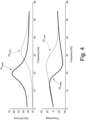
figure 4 is a diagram showing an optimal and desired transfer function and a corresponding measured transfer function. - In
figure 1 ,reference number 1 indicates, as a whole, a road vehicle provided with twofront wheels 2 and with tworear wheels 2. - The
road vehicle 1 is provided with a powertrain system (which is known and is not shown herein), which can comprise an internal combustion engine and/or one or more electric motors and can transmit a motion to thefront wheels 2 and/or to therear wheels 2. - A hub 3 (schematically shown in
figure 2 ) of eachwheel 2 is connected to a frame 4 of theroad vehicle 1 by means of a suspension 5 (partially shown infigure 1 ), which is provided with an (electronically controlled)active shock absorber 6, which is capable of making autonomous movements (namely, completely independent of the stresses transmitted by the road surface), which are added to the movements caused by the stresses transmitted by the road surface. - According to
figure 2 , eachactive shock absorber 6 comprises anelement 7, which defines an end of theactive shock absorber 6, and anelement 8, which defines the other end of theactive shock absorber 6 and is mounted so as to slide relative to theelement 7 in order to be able to linearly translate relative to theelement 7. Each active shock absorber 6 comprises aspring 9, which is connected between the twoelements elements active shock absorber 6 comprises an electric actuator 10 (typically, a rotary electric motor), which is configured to have the active shock absorber 6 make autonomous movements (namely, completely independent of the stresses transmitted by the road surface) between theelements elements active shock absorbers 6 could be of the type described in patent applicationsUS2008190104A1 andWO2014145215A2 . - Each active shock absorber 6 comprises a position sensor 11 (for example, a potentiometer), which provides the relative position p of the two
elements element 8 is translated relative to theelement 7. Furthermore, eachactive shock absorber 6 comprises a position sensor 11 (for example, a rotary encoder), which provides the angular position α of theelectric actuator 10. Theroad vehicle 1 comprises fourvertical accelerometers 13, which are mounted on thehubs 3 of thewheels 2, namely are rigidly fixed to thehubs 3 of thewheels 2 in order to move with thehubs 3 of thewheels 2 in an integral manner. Eachvertical accelerometer 13 is configured to measure a vertical acceleration az of thecorresponding hub 3. - According to
figure 1 , theroad vehicle 1 comprises alongitudinal accelerometer 14 and atransverse accelerometer 15, which are mounted on the frame 4, namely are rigidly fixed to the frame 4 in order to move with the frame in an integral manner 4, and are configured to measure a longitudinal acceleration ax and a transverse acceleration ay of the frame 4 (namely, of the road vehicle 1), respectively. According to a possible embodiment, the twoaccelerometers - The
road vehicle 1 comprises an electronic control unit ("ECU") 16, which, among other things, controls theactuators 10 of the active shock absorbers 6 in the ways described below; from a physical point of view, thecontrol unit 16 can consist of one single device or of several devices, which are separate from one another and communicate through the CAN network of theroad vehicle 1. Thecontrol unit 16 is connected (directly or indirectly through a BUS network of the road vehicle 1) to theposition sensors accelerometers - According to
figure 3 , thecontrol unit 16 implements anestimating block 17, which determines (estimates) a speed v of translation between the twoelements block 17 estimates the speed v of translation between the twoelements actuator 10 of the active shock absorber 6 (determined by deriving, in the time, the position p of theactuator 10 measured by the position sensor 12), based on the relative position p between the twoelements - According to
figure 3 , thecontrol unit 16 implements acontrol block 18, which, by using an open-loop transfer function TF1, determines a contribution C1 exclusively based on the sole vertical acceleration az in the area of the hub 3 (directly measured by the vertical accelerometer 13); in other words, the contribution C1 exclusively depends on the sole vertical acceleration az in the area of thehub 3. Furthermore, thecontrol unit 16 implements acontrol block 19, which, by using an open-loop transfer function TF2, determines a contribution C2 exclusively based on the sole speed v of translation between the twoelements elements control unit 16 implements anadder block 20, which calculates the target force FTGT of theactuator 10 by only and exclusively adding the two contributions C1 and C2 (it should be pointed out that the two contributions C1 and C2 also have a sign and, therefore, their sum is calculated taking into account the sign) ; namely, the value of the target force FTGT of theactuator 10 is exclusively determined by the sum of the sole contributions C1 and C2. - Basically, the open-loop transfer function TF2 entails the force F generated by the actuator 10 (namely, the contribution C2 of the target force FTGT of the actuator 10) being substantially proportional to the speed v of translation between the two
elements active shock absorber 6; namely, it increases as the speed v of translation between the twoelements active shock absorber 6 increases. Indeed, the gain of the transfer function TF2 is measured in [Ns/m] as, by being multiplied by the speed v of translation (measured in [m/s]), it directly provides the contribution C2 of the target force FTGT of the actuator 10 (measured in [N]). - In other words, the contribution C1 is determined based on the sole vertical acceleration az of the
hub 3 and using the open-loop transfer function TF1, which provides the contribution C1 based on the vertical acceleration az; similarly, the contribution C2 is determined based on the sole speed v of translation between the twoelements active shock absorber 6 and using the open-loop transfer function TF2, which provides the contribution C2 based on the speed v of translation. Hence, thecontrol unit 16 determines the target force FTGT based on the vertical acceleration az of thehub 3 and based on the speed v of translation between the twoelements - Basically, the contribution C1 determined based on the vertical acceleration az constitutes an inertia compensation, whereas the contribution C2 determined based on the speed v of translation between the two
elements - According to a preferred embodiment, the transfer functions TF1 and TF2 are variable as the frequency varies (generally, ranging from 0 to 50 Hz) and have a gain and a phase.
- To sum up, the
control unit 16 determines the target force FTGT for theactuator 10 of the active shock absorber 6 based on the vertical acceleration az of the hub 3 (directly measured by the vertical accelerometer 13) and based on the speed v of translation between the twoelements control unit 16 controls theactuator 10 of the active shock absorber 6 so as to pursue the target force FTGT; according to a preferred embodiment, the target force FTGT determined by thecontrol unit 16 only and exclusively based on the vertical acceleration az of thehub 3 and on the speed v of translation between the twoelements active shock absorber 6 could be added to other target forces determined in other ways and so as to pursue other targets (as described, for instance, inItalian patent applications 102021000015170 102021000015182 - According to a preferred embodiment, the transfer function TF2 consists of a map of experimentally determined points. In particular and according to
figure 4 , at first an optimal and desired transfer function TF2-OPT is established on paper in order to have an optimal and desired damping; subsequently, a measured transfer function TF2-MSR is experimentally determined by using mechanical stresses of thesuspension 5 and by always keeping the second contribution C2 at zero, namely by always having the target force FTGT coincide with the sole first contribution C1. Finally, the transfer function TF2-OPT is determined as difference between the optimal and desired transfer function TF2-OPT and the measured transfer function TF2-MSR. - The embodiments described herein can be combined with one another, without for this reason going beyond the scope of protection of the invention.
- The control method described above has different advantages.
- First of all, the control method disclosed above optimizes the damping response of the active shock absorber 6 (both in terms of effectiveness of the response and in terms of promptness of the response), though maintaining a hood level of comfort.
- Furthermore, the control method disclosed above is particularly stable and safe as, by operating in open loop, it never risks triggering undesired oscillations.
- Finally, the control method described above is simple and economic to be implemented, for it does not require either a significant calculation ability or a large memory space.
-
- 1
- vehicle
- 2
- wheels
- 3
- hub
- 4
- frame
- 5
- suspension
- 6
- active shock absorber
- 7
- element
- 8
- element
- 9
- spring
- 10
- electric actuator
- 11
- position sensor
- 12
- position sensor
- 13
- vertical accelerometer
- 14
- longitudinal accelerometer
- 15
- transverse accelerometer
- 16
- control unit
- 17
- estimating block
- 18
- control block
- 19
- control block
- 20
- adder block
- az
- vertical acceleration
- α
- angular position
- p
- angular position
- F
- force
- FTGT
- desired force
- F1
- transfer function
- F2
- transfer function
- TF2-OPT
- optimal transfer function
- TF2-MSR
- measured transfer function
- C1
- contribution
- C2
- contribution
Claims (14)
- A method to control a road vehicle (1) comprising;a frame (4) ;at least one wheel (2) provided with a hub (3); anda suspension (5), which connects the frame (4) to the hub (3) of the wheel (2) and is provided with an active shock absorber (6) comprising: a first element (7), which defines an end of the active shock absorber (6), a second element (8), which defines another end of the active shock absorber (6) and is mounted so as to slide relative to the first element (7); and an actuator (10), which is configured to generate a force (F), which is applied between the two elements (7, 8);the control method comprises the steps of:determining a vertical acceleration (az) of the hub (3) ;determining a speed (v) of translation between the two elements (7, 8) of the active shock absorber (6);determining a target force (FTGT) for the actuator (10) of the active shock absorber (6) based on the vertical acceleration (az) of the hub (3) and on the speed (v) of translation between the two elements (7, 8) of the active shock absorber (6); andcontrolling the actuator (10) of the active shock absorber (6) so as to pursue the target force (FTGT);the control method is characterized in that it comprises the further steps of:determining a first contribution (C1) exclusively based on the sole vertical acceleration (az) of the hub (3) and using a first open-loop transfer function (TF1), which provides the first contribution (C1) exclusively as a function of the sole vertical acceleration (az);determining a second contribution (C2) exclusively based on the sole speed (v) of translation between the two elements (7, 8) of the active shock absorber (6) and using a second open-loop transfer function (TF2), which provides the second contribution (C2) exclusively as a function of the sole translation speed (v); andcalculating the target force (FTGT) by adding the two contributions (C1, C2).
- The control method according to claim 1, wherein the target force (FTGT) is calculated by only and exclusively adding the two contributions (C1, C2).
- The control method according to claim 1 or 2, wherein the second transfer function (TF2) consists of a map of experimentally determined points.
- The control method according to claim 1, 2 or 3 and comprising the further steps of:establishing a second optimal and desired transfer function (F2-OPT);experimentally determining a second measured transfer function (TF2-MSR) by using mechanical stresses of the suspension (5) and by always keeping the second contribution (C2) at zero, namely always having the target force (FTGT) coincide with the sole first contribution (C1); anddetermining the second transfer function (TF2-OPT) as difference between the second optimal and desired transfer function (TF2-OPT) and the second measured transfer function (TF2-MSR).
- The control method according to one of the claims from 1 to 4, wherein the second transfer function (TF2-OPT) is variable as the frequency varies.
- The control method according to one of the claims from 1 to 5, wherein the second transfer function (TF2-OPT) has a gain having [Ns/m] as unit of measurement and a phase expressed in degrees.
- The control method according to one of the claims from 1 to 6, wherein the second open-loop transfer function (TF2-OPT) entails the second contribution (C2) being proportional to the speed (v) of translation between the two elements (7, 8) of the active shock absorber (6).
- The control method according to one of the claims from 1 to 7, wherein the second open-loop transfer function (TF2-OPT) entails the second contribution (C2) increasing as the speed (v) of translation between the two elements (7, 8) of the active shock absorber (6) increases.
- The control method according to one of the claims from 1 to 8, wherein the first transfer function (TF1) is variable as the frequency varies.
- The control method according to one of the claims from 1 to 9 and comprising the further step of estimating the speed (v) of translation between the two elements (7, 8) of the active shock absorber (6) based on a moving speed of the actuator (10) of the active shock absorber (6).
- The control method according to claim 10 and comprising the further step of estimating the speed (v) of translation between the two elements (7, 8) of the active shock absorber (6) also based on a relative position (p) between the two elements (7, 8) of the active shock absorber (6).
- The control method according to claim 10 or 11 and comprising the further step of estimating the speed (v) of translation between the two elements (7, 8) of the active shock absorber (6) also based on the vertical acceleration (az) of the hub (3) .
- The control method according to one of the claims from 1 to 12 and comprising the further step of estimating the speed (v) of translation between the two elements (7, 8) of the active shock absorber (6) only and exclusively based on a moving speed of the actuator (10) of the active shock absorber (6), on a relative position (p) between the two elements (7, 8) of the active shock absorber (6) and on the vertical acceleration (az) of the hub (3).
- The control method according to one of the claims from 1 to 13, wherein the active shock absorber (6) comprises a spring (9), which is connected between the two elements (7, 8) and is compressed or expanded when the two elements (7, 8) linearly translate relative to one another.
Applications Claiming Priority (1)
| Application Number | Priority Date | Filing Date | Title |
|---|---|---|---|
| IT102022000007496A IT202200007496A1 (en) | 2022-04-14 | 2022-04-14 | METHOD OF CONTROL OF AN ACTIVE SHOCK ABSORBER OF A ROAD VEHICLE |
Publications (2)
| Publication Number | Publication Date |
|---|---|
| EP4261061A1 true EP4261061A1 (en) | 2023-10-18 |
| EP4261061B1 EP4261061B1 (en) | 2024-12-04 |
Family
ID=82385710
Family Applications (1)
| Application Number | Title | Priority Date | Filing Date |
|---|---|---|---|
| EP23167686.7A Active EP4261061B1 (en) | 2022-04-14 | 2023-04-13 | Method to control a road vehicle |
Country Status (5)
| Country | Link |
|---|---|
| US (1) | US12358334B2 (en) |
| EP (1) | EP4261061B1 (en) |
| JP (1) | JP2023157857A (en) |
| CN (1) | CN116901635A (en) |
| IT (1) | IT202200007496A1 (en) |
Families Citing this family (1)
| Publication number | Priority date | Publication date | Assignee | Title |
|---|---|---|---|---|
| CN118494094B (en) * | 2024-06-19 | 2026-01-13 | 中国第一汽车股份有限公司 | Control method, device, system, module and vehicle for double-valve shock absorber |
Citations (3)
| Publication number | Priority date | Publication date | Assignee | Title |
|---|---|---|---|---|
| US20080190104A1 (en) | 2007-02-13 | 2008-08-14 | The Board Of Regents Of The University Of Texas System | Actuators |
| WO2014145215A2 (en) | 2013-03-15 | 2014-09-18 | Levant Power Corporation | Active suspension with on-demand energy |
| US20180134111A1 (en) | 2016-03-16 | 2018-05-17 | Honda Motor Co., Ltd. | Vehicle suspension system |
Family Cites Families (4)
| Publication number | Priority date | Publication date | Assignee | Title |
|---|---|---|---|---|
| US5129488A (en) * | 1989-11-16 | 1992-07-14 | Atsugi Unisia Corporation | Vibration mode responsive variable damping force shock absorber with feature of automatic selection of damping mode depending upon vibration mode of vehicular body |
| JP5463263B2 (en) * | 2009-11-30 | 2014-04-09 | 日立オートモティブシステムズ株式会社 | Suspension control device for vehicle |
| JP6480983B2 (en) * | 2017-06-16 | 2019-03-13 | 本田技研工業株式会社 | Electromagnetic suspension device |
| JP6923591B2 (en) * | 2019-04-12 | 2021-08-18 | 本田技研工業株式会社 | Electric suspension device |
-
2022
- 2022-04-14 IT IT102022000007496A patent/IT202200007496A1/en unknown
-
2023
- 2023-04-06 JP JP2023062157A patent/JP2023157857A/en active Pending
- 2023-04-10 US US18/297,947 patent/US12358334B2/en active Active
- 2023-04-13 EP EP23167686.7A patent/EP4261061B1/en active Active
- 2023-04-14 CN CN202310400330.9A patent/CN116901635A/en active Pending
Patent Citations (3)
| Publication number | Priority date | Publication date | Assignee | Title |
|---|---|---|---|---|
| US20080190104A1 (en) | 2007-02-13 | 2008-08-14 | The Board Of Regents Of The University Of Texas System | Actuators |
| WO2014145215A2 (en) | 2013-03-15 | 2014-09-18 | Levant Power Corporation | Active suspension with on-demand energy |
| US20180134111A1 (en) | 2016-03-16 | 2018-05-17 | Honda Motor Co., Ltd. | Vehicle suspension system |
Also Published As
| Publication number | Publication date |
|---|---|
| EP4261061B1 (en) | 2024-12-04 |
| JP2023157857A (en) | 2023-10-26 |
| IT202200007496A1 (en) | 2023-10-14 |
| CN116901635A (en) | 2023-10-20 |
| US12358334B2 (en) | 2025-07-15 |
| US20230331055A1 (en) | 2023-10-19 |
Similar Documents
| Publication | Publication Date | Title |
|---|---|---|
| EP4101665B1 (en) | Method to control the active shock absorbers of a road vehicle featuring the lowering of the centre of gravity | |
| US12128727B2 (en) | Method to control the active shock absorbers of a road vehicle featuring the adjustment of the roll angle and of the pitch angle | |
| EP1346856B1 (en) | A system and method for determining the roll angle of a vehicle | |
| US6556908B1 (en) | Attitude sensing system for an automotive vehicle relative to the road | |
| JP5224039B2 (en) | Suspension control device | |
| US7480547B2 (en) | Attitude sensing system for an automotive vehicle relative to the road | |
| EP3865359B1 (en) | Method to control, while driving along a curve, a road vehicle with a variable stiffness and with rear steering wheels | |
| US20060076740A1 (en) | Braking and drive force control apparatus for a vehicle | |
| JP6753911B2 (en) | Control device for variable damping force damper | |
| KR20110014078A (en) | Suspension control unit | |
| EP4261061B1 (en) | Method to control a road vehicle | |
| US11052718B2 (en) | Active suspension control unit and method | |
| JPH1191329A (en) | Ground load control device | |
| JP7600944B2 (en) | Vehicle suspension control device and vehicle suspension control method | |
| JP3779441B2 (en) | Vehicle collision avoidance control device | |
| JP3814057B2 (en) | Ground load control device | |
| Yasuda et al. | Improvement of vehicle motion and riding-comfort by active controlled suspension system | |
| JP3814056B2 (en) | Ground load control device | |
| JP5104594B2 (en) | Vehicle control device | |
| CN121608610A (en) | A method for controlling front independent suspension | |
| JP3377115B2 (en) | Method and apparatus for closed-loop and / or open-loop control of a closed-loop and / or open-loop controllable chassis | |
| JP3904289B2 (en) | Ground load control device | |
| JPH10305717A (en) | Ground load control device | |
| JPH1111130A (en) | Ground load control device | |
| JPH1134627A (en) | Ground load control device |
Legal Events
| Date | Code | Title | Description |
|---|---|---|---|
| PUAI | Public reference made under article 153(3) epc to a published international application that has entered the european phase |
Free format text: ORIGINAL CODE: 0009012 |
|
| STAA | Information on the status of an ep patent application or granted ep patent |
Free format text: STATUS: THE APPLICATION HAS BEEN PUBLISHED |
|
| AK | Designated contracting states |
Kind code of ref document: A1 Designated state(s): AL AT BE BG CH CY CZ DE DK EE ES FI FR GB GR HR HU IE IS IT LI LT LU LV MC ME MK MT NL NO PL PT RO RS SE SI SK SM TR |
|
| STAA | Information on the status of an ep patent application or granted ep patent |
Free format text: STATUS: REQUEST FOR EXAMINATION WAS MADE |
|
| 17P | Request for examination filed |
Effective date: 20240410 |
|
| RBV | Designated contracting states (corrected) |
Designated state(s): AL AT BE BG CH CY CZ DE DK EE ES FI FR GB GR HR HU IE IS IT LI LT LU LV MC ME MK MT NL NO PL PT RO RS SE SI SK SM TR |
|
| RIC1 | Information provided on ipc code assigned before grant |
Ipc: B60G 17/06 20060101AFI20240522BHEP |
|
| GRAP | Despatch of communication of intention to grant a patent |
Free format text: ORIGINAL CODE: EPIDOSNIGR1 |
|
| STAA | Information on the status of an ep patent application or granted ep patent |
Free format text: STATUS: GRANT OF PATENT IS INTENDED |
|
| INTG | Intention to grant announced |
Effective date: 20240702 |
|
| GRAS | Grant fee paid |
Free format text: ORIGINAL CODE: EPIDOSNIGR3 |
|
| GRAA | (expected) grant |
Free format text: ORIGINAL CODE: 0009210 |
|
| STAA | Information on the status of an ep patent application or granted ep patent |
Free format text: STATUS: THE PATENT HAS BEEN GRANTED |
|
| AK | Designated contracting states |
Kind code of ref document: B1 Designated state(s): AL AT BE BG CH CY CZ DE DK EE ES FI FR GB GR HR HU IE IS IT LI LT LU LV MC ME MK MT NL NO PL PT RO RS SE SI SK SM TR |
|
| REG | Reference to a national code |
Ref country code: CH Ref legal event code: EP |
|
| REG | Reference to a national code |
Ref country code: DE Ref legal event code: R096 Ref document number: 602023001226 Country of ref document: DE |
|
| REG | Reference to a national code |
Ref country code: IE Ref legal event code: FG4D |
|
| REG | Reference to a national code |
Ref country code: LT Ref legal event code: MG9D |
|
| REG | Reference to a national code |
Ref country code: NL Ref legal event code: MP Effective date: 20241204 |
|
| PG25 | Lapsed in a contracting state [announced via postgrant information from national office to epo] |
Ref country code: HR Free format text: LAPSE BECAUSE OF FAILURE TO SUBMIT A TRANSLATION OF THE DESCRIPTION OR TO PAY THE FEE WITHIN THE PRESCRIBED TIME-LIMIT Effective date: 20241204 |
|
| PG25 | Lapsed in a contracting state [announced via postgrant information from national office to epo] |
Ref country code: FI Free format text: LAPSE BECAUSE OF FAILURE TO SUBMIT A TRANSLATION OF THE DESCRIPTION OR TO PAY THE FEE WITHIN THE PRESCRIBED TIME-LIMIT Effective date: 20241204 |
|
| PG25 | Lapsed in a contracting state [announced via postgrant information from national office to epo] |
Ref country code: BG Free format text: LAPSE BECAUSE OF FAILURE TO SUBMIT A TRANSLATION OF THE DESCRIPTION OR TO PAY THE FEE WITHIN THE PRESCRIBED TIME-LIMIT Effective date: 20241204 |
|
| PG25 | Lapsed in a contracting state [announced via postgrant information from national office to epo] |
Ref country code: ES Free format text: LAPSE BECAUSE OF FAILURE TO SUBMIT A TRANSLATION OF THE DESCRIPTION OR TO PAY THE FEE WITHIN THE PRESCRIBED TIME-LIMIT Effective date: 20241204 |
|
| PG25 | Lapsed in a contracting state [announced via postgrant information from national office to epo] |
Ref country code: NO Free format text: LAPSE BECAUSE OF FAILURE TO SUBMIT A TRANSLATION OF THE DESCRIPTION OR TO PAY THE FEE WITHIN THE PRESCRIBED TIME-LIMIT Effective date: 20250304 |
|
| PG25 | Lapsed in a contracting state [announced via postgrant information from national office to epo] |
Ref country code: GR Free format text: LAPSE BECAUSE OF FAILURE TO SUBMIT A TRANSLATION OF THE DESCRIPTION OR TO PAY THE FEE WITHIN THE PRESCRIBED TIME-LIMIT Effective date: 20250305 Ref country code: LV Free format text: LAPSE BECAUSE OF FAILURE TO SUBMIT A TRANSLATION OF THE DESCRIPTION OR TO PAY THE FEE WITHIN THE PRESCRIBED TIME-LIMIT Effective date: 20241204 |
|
| PG25 | Lapsed in a contracting state [announced via postgrant information from national office to epo] |
Ref country code: RS Free format text: LAPSE BECAUSE OF FAILURE TO SUBMIT A TRANSLATION OF THE DESCRIPTION OR TO PAY THE FEE WITHIN THE PRESCRIBED TIME-LIMIT Effective date: 20250304 |
|
| PG25 | Lapsed in a contracting state [announced via postgrant information from national office to epo] |
Ref country code: NL Free format text: LAPSE BECAUSE OF FAILURE TO SUBMIT A TRANSLATION OF THE DESCRIPTION OR TO PAY THE FEE WITHIN THE PRESCRIBED TIME-LIMIT Effective date: 20241204 |
|
| REG | Reference to a national code |
Ref country code: AT Ref legal event code: MK05 Ref document number: 1747813 Country of ref document: AT Kind code of ref document: T Effective date: 20241204 |
|
| PG25 | Lapsed in a contracting state [announced via postgrant information from national office to epo] |
Ref country code: SM Free format text: LAPSE BECAUSE OF FAILURE TO SUBMIT A TRANSLATION OF THE DESCRIPTION OR TO PAY THE FEE WITHIN THE PRESCRIBED TIME-LIMIT Effective date: 20241204 |
|
| PG25 | Lapsed in a contracting state [announced via postgrant information from national office to epo] |
Ref country code: PL Free format text: LAPSE BECAUSE OF FAILURE TO SUBMIT A TRANSLATION OF THE DESCRIPTION OR TO PAY THE FEE WITHIN THE PRESCRIBED TIME-LIMIT Effective date: 20241204 |
|
| PGFP | Annual fee paid to national office [announced via postgrant information from national office to epo] |
Ref country code: DE Payment date: 20250428 Year of fee payment: 3 |
|
| PG25 | Lapsed in a contracting state [announced via postgrant information from national office to epo] |
Ref country code: IS Free format text: LAPSE BECAUSE OF FAILURE TO SUBMIT A TRANSLATION OF THE DESCRIPTION OR TO PAY THE FEE WITHIN THE PRESCRIBED TIME-LIMIT Effective date: 20250404 |
|
| PGFP | Annual fee paid to national office [announced via postgrant information from national office to epo] |
Ref country code: IT Payment date: 20250430 Year of fee payment: 3 |
|
| PG25 | Lapsed in a contracting state [announced via postgrant information from national office to epo] |
Ref country code: PT Free format text: LAPSE BECAUSE OF FAILURE TO SUBMIT A TRANSLATION OF THE DESCRIPTION OR TO PAY THE FEE WITHIN THE PRESCRIBED TIME-LIMIT Effective date: 20250404 |
|
| PG25 | Lapsed in a contracting state [announced via postgrant information from national office to epo] |
Ref country code: EE Free format text: LAPSE BECAUSE OF FAILURE TO SUBMIT A TRANSLATION OF THE DESCRIPTION OR TO PAY THE FEE WITHIN THE PRESCRIBED TIME-LIMIT Effective date: 20241204 |
|
| PGFP | Annual fee paid to national office [announced via postgrant information from national office to epo] |
Ref country code: FR Payment date: 20250424 Year of fee payment: 3 |
|
| PG25 | Lapsed in a contracting state [announced via postgrant information from national office to epo] |
Ref country code: RO Free format text: LAPSE BECAUSE OF FAILURE TO SUBMIT A TRANSLATION OF THE DESCRIPTION OR TO PAY THE FEE WITHIN THE PRESCRIBED TIME-LIMIT Effective date: 20241204 Ref country code: AT Free format text: LAPSE BECAUSE OF FAILURE TO SUBMIT A TRANSLATION OF THE DESCRIPTION OR TO PAY THE FEE WITHIN THE PRESCRIBED TIME-LIMIT Effective date: 20241204 |
|
| PG25 | Lapsed in a contracting state [announced via postgrant information from national office to epo] |
Ref country code: SK Free format text: LAPSE BECAUSE OF FAILURE TO SUBMIT A TRANSLATION OF THE DESCRIPTION OR TO PAY THE FEE WITHIN THE PRESCRIBED TIME-LIMIT Effective date: 20241204 |
|
| PG25 | Lapsed in a contracting state [announced via postgrant information from national office to epo] |
Ref country code: CZ Free format text: LAPSE BECAUSE OF FAILURE TO SUBMIT A TRANSLATION OF THE DESCRIPTION OR TO PAY THE FEE WITHIN THE PRESCRIBED TIME-LIMIT Effective date: 20241204 |
|
| REG | Reference to a national code |
Ref country code: DE Ref legal event code: R097 Ref document number: 602023001226 Country of ref document: DE |
|
| PG25 | Lapsed in a contracting state [announced via postgrant information from national office to epo] |
Ref country code: SE Free format text: LAPSE BECAUSE OF FAILURE TO SUBMIT A TRANSLATION OF THE DESCRIPTION OR TO PAY THE FEE WITHIN THE PRESCRIBED TIME-LIMIT Effective date: 20241204 |
|
| PG25 | Lapsed in a contracting state [announced via postgrant information from national office to epo] |
Ref country code: DK Free format text: LAPSE BECAUSE OF FAILURE TO SUBMIT A TRANSLATION OF THE DESCRIPTION OR TO PAY THE FEE WITHIN THE PRESCRIBED TIME-LIMIT Effective date: 20241204 |
|
| PLBE | No opposition filed within time limit |
Free format text: ORIGINAL CODE: 0009261 |
|
| STAA | Information on the status of an ep patent application or granted ep patent |
Free format text: STATUS: NO OPPOSITION FILED WITHIN TIME LIMIT |
|
| 26N | No opposition filed |
Effective date: 20250905 |
|
| PG25 | Lapsed in a contracting state [announced via postgrant information from national office to epo] |
Ref country code: LU Free format text: LAPSE BECAUSE OF NON-PAYMENT OF DUE FEES Effective date: 20250413 |
|
| PG25 | Lapsed in a contracting state [announced via postgrant information from national office to epo] |
Ref country code: MC Free format text: LAPSE BECAUSE OF FAILURE TO SUBMIT A TRANSLATION OF THE DESCRIPTION OR TO PAY THE FEE WITHIN THE PRESCRIBED TIME-LIMIT Effective date: 20241204 |
|
| REG | Reference to a national code |
Ref country code: BE Ref legal event code: MM Effective date: 20250430 |
|
| PG25 | Lapsed in a contracting state [announced via postgrant information from national office to epo] |
Ref country code: BE Free format text: LAPSE BECAUSE OF NON-PAYMENT OF DUE FEES Effective date: 20250430 |
|
| PG25 | Lapsed in a contracting state [announced via postgrant information from national office to epo] |
Ref country code: IE Free format text: LAPSE BECAUSE OF NON-PAYMENT OF DUE FEES Effective date: 20250413 |