EP4261010A1 - Apparatus and process for producing a trim panel - Google Patents
Apparatus and process for producing a trim panel Download PDFInfo
- Publication number
- EP4261010A1 EP4261010A1 EP22305517.9A EP22305517A EP4261010A1 EP 4261010 A1 EP4261010 A1 EP 4261010A1 EP 22305517 A EP22305517 A EP 22305517A EP 4261010 A1 EP4261010 A1 EP 4261010A1
- Authority
- EP
- European Patent Office
- Prior art keywords
- clamping
- mold section
- surface area
- cover sheet
- clamping member
- Prior art date
- Legal status (The legal status is an assumption and is not a legal conclusion. Google has not performed a legal analysis and makes no representation as to the accuracy of the status listed.)
- Granted
Links
Images



Classifications
-
- B—PERFORMING OPERATIONS; TRANSPORTING
- B29—WORKING OF PLASTICS; WORKING OF SUBSTANCES IN A PLASTIC STATE IN GENERAL
- B29C—SHAPING OR JOINING OF PLASTICS; SHAPING OF MATERIAL IN A PLASTIC STATE, NOT OTHERWISE PROVIDED FOR; AFTER-TREATMENT OF THE SHAPED PRODUCTS, e.g. REPAIRING
- B29C51/00—Shaping by thermoforming, i.e. shaping sheets or sheet like preforms after heating, e.g. shaping sheets in matched moulds or by deep-drawing; Apparatus therefor
- B29C51/16—Lining or labelling
-
- B—PERFORMING OPERATIONS; TRANSPORTING
- B29—WORKING OF PLASTICS; WORKING OF SUBSTANCES IN A PLASTIC STATE IN GENERAL
- B29C—SHAPING OR JOINING OF PLASTICS; SHAPING OF MATERIAL IN A PLASTIC STATE, NOT OTHERWISE PROVIDED FOR; AFTER-TREATMENT OF THE SHAPED PRODUCTS, e.g. REPAIRING
- B29C51/00—Shaping by thermoforming, i.e. shaping sheets or sheet like preforms after heating, e.g. shaping sheets in matched moulds or by deep-drawing; Apparatus therefor
- B29C51/26—Component parts, details or accessories; Auxiliary operations
- B29C51/261—Handling means, e.g. transfer means, feeding means
- B29C51/262—Clamping means for the sheets, e.g. clamping frames
-
- B—PERFORMING OPERATIONS; TRANSPORTING
- B29—WORKING OF PLASTICS; WORKING OF SUBSTANCES IN A PLASTIC STATE IN GENERAL
- B29C—SHAPING OR JOINING OF PLASTICS; SHAPING OF MATERIAL IN A PLASTIC STATE, NOT OTHERWISE PROVIDED FOR; AFTER-TREATMENT OF THE SHAPED PRODUCTS, e.g. REPAIRING
- B29C51/00—Shaping by thermoforming, i.e. shaping sheets or sheet like preforms after heating, e.g. shaping sheets in matched moulds or by deep-drawing; Apparatus therefor
- B29C51/08—Deep drawing or matched-mould forming, i.e. using mechanical means only
- B29C51/082—Deep drawing or matched-mould forming, i.e. using mechanical means only by shaping between complementary mould parts
- B29C51/087—Deep drawing or matched-mould forming, i.e. using mechanical means only by shaping between complementary mould parts with at least one of the mould parts comprising independently movable sections
-
- B—PERFORMING OPERATIONS; TRANSPORTING
- B29—WORKING OF PLASTICS; WORKING OF SUBSTANCES IN A PLASTIC STATE IN GENERAL
- B29L—INDEXING SCHEME ASSOCIATED WITH SUBCLASS B29C, RELATING TO PARTICULAR ARTICLES
- B29L2031/00—Other particular articles
- B29L2031/30—Vehicles, e.g. ships or aircraft, or body parts thereof
- B29L2031/3005—Body finishings
- B29L2031/3041—Trim panels
Definitions
- the present invention concerns the manufacturing of trim panels having at least a substrate and a cover sheet laminated to said substrate.
- the cover sheet is laminated on the substrate by moving the first mold section against the second mold section, such that the first surface area is pressed against the second surface area.
- An objective of the invention is to propose an apparatus/ process that does not present said drawback.
- an apparatus for producing a trim panel having at least a substrate and a cover sheet laminated to said substrate comprising:
- the cover sheet Since an edge of the cover sheet is clamped between the first clamping member and the second clamping member in the clamping position, the cover sheet is properly controlled when the first mold section and the second mold section are moved to the molding position. It is possible to avoid that material accumulates in curved or corner areas, creating unwanted folds in the cover sheet. The appearance of the trim part is improved.
- the apparatus may present one or several of the following features, considered alone or according to any technically feasible combination:
- the invention relates to a process for producing a trim panel having at least a substrate and a cover sheet laminated to said substrate, the process comprising the following steps:
- the process may comprise the following additional steps:
- the apparatus 10 depicted on the figures 1 to 6 is for producing a trim panel 12 having at least a substrate 14 and a cover sheet 16 laminated to said substrate 14.
- the trim panel 12 is for example used to cover the inner surface of automobile doors, or the dashboard, or any other surface of the cockpit of the vehicle.
- the trim panel 12 may be a sun visor.
- the substrate 14 is a panel of a substantially rigid material. It is typically made of a plastic material such as Acrylonitrile Butadiene Styrene (ABS), Polycarbonate/Acrylonitrile Butadiene Styrene (PC/ABS), Polyproylene (PP).
- ABS Acrylonitrile Butadiene Styrene
- PC/ABS Polycarbonate/Acrylonitrile Butadiene Styrene
- PP Polyproylene
- the cover sheet 16 is a decorative sheet, visible for the passengers of the vehicle.
- the cover sheet 16 has a decorative layer, typically made of a plastic material, a textile, a leather or a genuine material such as wood, stone ....
- the cover sheet 16 comprises a foam backing arranged on the back of the decorative layer.
- the cover sheet 16 is flexible and can be folded when exerting a pressure of average magnitude.
- the apparatus 10 comprises:
- the first surface area 20 has the shape required for the inner surface of the trim part.
- the inner surface is the surface typically turned opposite the cockpit of the vehicle and not visible by the passengers.
- the holding device 22 is for example a vacuum device, or a mechanical clamping device, or any other device adapted for holding the substrate 14 against the first surface area 20.
- the second surface area 26 has the shape required for the outer surface of the trim part.
- the outer surface is the surface typically turned toward the cockpit of the vehicle and visible by the passengers.
- the first surface area 20 has a shape complementary of the shape of the second surface area 26. It means that the first surface area 20 can fit against the second surface area 26 with a little or no spacing between them.
- the first surface area 20 is convex, and the second surface area 26 is concave.
- the main drive 29 is for example an hydraulic cylinder, or a pneumatic cylinder, or any other type of actuator.
- the main drive 29 typically moves the first mold section 18 with respect to the second mold section 24 longitudinally between the molding position and the open position.
- the longitudinal direction L is shown on the figures.
- the second mold section 24 is fixed, and the first mold section 18 is moved by the main drive 29.
- the first mold section 20 is fixed, and the second mold section 24 is moved by the main drive 29.
- the first mold section 20 and the second mold section 24 are moved by the main drive 29.
- first mold section 18 moves in translation with respect to the second mold section 24 between the molding position and the open position, along the longitudinal direction shown on the figures.
- the displacement of the first mold section is not a translation. It is a rotation or a combination of translation(s) and rotation(s).
- the first surface area 20 and the second surface area 26 are pressed against one another with the substrate 14 and the cover sheet 16 between them in the molding position ( figures 3 to 6 ).
- the first surface area 20 and the second surface area 26 are away from one another in the open position ( figures 1 and 2 ).
- the first surface area 20 and the second surface area 26 are located one in front of the other.
- the clamping frame 28 comprises a first clamping member 30, a second clamping member 32 and a clamping drive 34 moving the first clamping member 30 and the second clamping member 32 with respect to one another between a cover sheet clamping position ( figures 2 and 3 ) and a cover sheet release position ( figure 1 ).
- An edge 36 of the cover sheet 16 is clamped between the first clamping member 30 and the second clamping member 32 in the clamping position.
- the edge 36 of the cover sheet 16 is free with respect to the first clamping member 30 and/or the second clamping member 32 in the release position.
- the first clamping member 30 is a frame.
- It has a substantially closed contour, and surrounds an empty space. It is arranged around the first mold section 18, as shown on the figures.
- the second clamping member 32 has a substantially closed contour. It surrounds an empty space. It is arranged around the second surface area 26, as shown on the figures.
- the first clamping member 30 has a first clamping surface 38.
- the second clamping member 32 has a second clamping surface 40.
- the first clamping surface 30 and the second clamping surface 32 clamp the edge 36 of the cover sheet 16 between them in the clamping position ( figure 2 ).
- the first clamping surface 30 is turned longitudinally in one direction, toward the second clamping section 24.
- the second clamping surface 32 is turned longitudinally in the opposite direction.
- the cover sheet 16 extends between the first surface area 20 and the second surface area 26 in the clamping position of the clamping frame 30.
- the clamping drive 34 is typically a pneumatic or hydraulic cylinder or any other type of actuator.
- the clamping drive 34 moves the first clamping member 30 longitudinally in translation with respect to the second clamping member 32.
- the clamping frame 28 is arranged for adjusting the clamping force by which the edge 36 of the cover sheet 16 is clamped between the first clamping member 30 and the second clamping member 32 in the clamping position.
- the clamping frame 28 comprises for this purpose an adjustable stopper 42, able to adjust the spacing between the first clamping surface 38 and the second clamping surface 40 in the clamping position.
- the adjustable stopper 42 comprises for example one or several screws, mounted on the first clamping member 30.
- the or each screw protrudes longitudinally with respect to a lower surface 43 of the first clamping member 30 turned tower the second clamping member 32.
- the height by which the or each screw protrudes is adjustable. In the clamping position, the adjustable stopper 42 is in abutment against an upper surface 44 of the second clamping member 32.
- Changing the position of the screws with respect to the lower surface 44 allows changing the longitudinal position of the first clamping member 30 with respect to the second clamping member 32 in the clamping position, and thus the longitudinal position of the first clamping surface 38 with respect to the second clamping surface 40 in the clamping position. This in turn allows changing the longitudinal spacing between the first clamping surface 38 and the second clamping surface 40 in the clamping position.
- the clamping force by which the edge 36 of the cover sheet 16 is clamped between the first clamping member 30 and the second clamping member 32 in the clamping position can be adjusted as well by changing the force applied by clamping drive 34.
- a supplement is spacer having a reduced thickness, arranged between the piston of the cylinder and the first clamping member 30, for example a washer or a plate. Adding or removing one or several supplements allows changing the longitudinal position of the first clamping surface 38 with respect to the second clamping surface 40 in the clamping position and thus the longitudinal spacing between the first clamping surface 38 and the second clamping surface 40.
- the first mold section 18 comprises a main part 45 defining a main area 46 of the first surface area 20, and at least one longitudinal slider 48 movable with respect to the main part 44 between an extended position ( figures 1 to 3 ) and a retracted position ( figures 4 and 5 ).
- the at least one longitudinal slider 48 is displaced with respect to the main part 44 by an actuator, not shown on the figures.
- the actuator is typically a cylinder, pneumatic or hydraulic.
- the or each longitudinal slider 48 defines a first surface edge area 50 of the first surface area 20 in the extended position.
- the or each longitudinal slider 48 is retracted longitudinally away from the first surface area 20 in the retracted position.
- the or each longitudinal slider 48 is for folding the edge of the cover sheet 16 around the free edge of the substrate 14, as will be described further down.
- the second clamping member 32 comprises at least one transverse slider 52, movable with respect to the second mold section 24 between an outer position ( figures 1 to 4 ) and an inner position ( figure 5 ).
- the or each transverse slider 52 in the inner position extends longitudinally in front of the at least one longitudinal slider 48 when the first mold section 18 is in the molding position with respect to the second mold section 24 and the at least one longitudinal slider 48 is in the retracted position.
- the first surface edge area 50 is pressed against a corresponding area 54 of the second surface area 26 ( figure 3 ).
- the or each transverse slider 52 in the outer position does not extend longitudinally in front of the at least one longitudinal slider 48. It does not extend, longitudinally, in front of the second surface area 26.
- the or each transverse slider 52 defines a part of the second clamping surface 40.
- the second surface area 26 is a depression, surrounded by an upper edge 57 having a closed contour.
- a part of the second clamping member 32 is made by at least one portion of the upper edge 57, and another part of the second clamping member 32 is made by the or each transverse slider 52.
- a part of the second clamping surface 40 is made by at least one portion of the upper edge 57, and another part of the second clamping surface 40 is made by the or each transverse slider 52.
- the second clamping member 32 comprises several transverse sliders 52
- the second clamping member 32 comprises several portions of the upper edge 57, separated from one another by the transverse sliders 52.
- trim panel 12 The process for producing the trim panel 12 will be detailed below.
- the process is designed for being implemented using the apparatus 10 described above. Conversely, the apparatus 10 is particularly adapted for carrying out the process detailed below.
- the process comprises the following steps:
- the main drive 29 moves the first mold section 18 with respect to the second mold section 24 longitudinally between the molding position and the open position.
- the first mold section 18 is as described above.
- clamping frame 28, the first clamping member 30 and the second clamping member 32 are as described above.
- the step of arranging the substrate 12 against the first surface area 20 and the step of arranging the cover sheet 16 in the clamping frame 28 are carried out with the first mold section 18 and the second mold section 24 in an open position with respect to one another.
- the first surface area 20 and the second surface area 26 are away from one another in the open position, as shown in the figure 1 .
- the substrate 14 is arranged against the first surface area 20 by mean of a holding device 22.
- the holding device 22, as described above, is for example a vacuum device, or a mechanical clamping device.
- the cover sheet 16 is arranged in the clamping frame 28 as shown in the figures 1 and 2 .
- the first clamping member 30 and the second clamping member 32 are initially in a release position with respect to one another ( figure 1 ).
- the first clamping member 30 and the second clamping member 32 are longitudinally away from one another.
- the cover sheet 16 is secured to the second clamping member 32, for example using pins (not shown on the figures) arranged on the second clamping surface 40.
- first clamping member 30 and the second clamping member 32 are brought to a cover sheet clamping position with respect to one another ( figure 2 ).
- the first clamping member 30 is moved longitudinally with respect to the second clamping member 32.
- the first clamping member 30 stops when the adjustable stopper 42 comes in abutment against the upper surface 44 of the second clamping member 32.
- the edge 36 of the cover sheet 14 is clamped between the first clamping member 30 and the second clamping member 32 in the clamping position, and more specifically between the first clamping surface 38 and the second clamping surface 40.
- the spacing between the first clamping surface 38 and the second clamping surface 40 in the clamping position is adjusted by mean of the adjustable stopper 42.
- the adjustable stopper 42 is as described above.
- the edge 36 of the cover sheet must be strongly clamped, such that the position of the edge 36 does not shift when the first molding section 18 and the second molding section 24 are brought to the molding position. In other instances, the edge 36 of the cover sheet must be less strongly clamped, such that the position of the edge 36 is allowed to shift when the first molding section 18 and the second molding section 24 are brought to the molding position.
- the clamping force is adjusted by changing the force applied by clamping drive 34, and/or using supplements arranged between the clamping drive 34 and the first clamping member 30, as described above.
- the molding position is shown on the figure 3 .
- the substrate 14 and a central part 58 of the cover sheet 16 are pinched between the first surface area 20 and the second area 26.
- the central part 58 of the cover sheet 16 covers an outer surface 59 of the substrate 14.
- the edge 36 of the cover sheet is clamped between the first clamping member 30 and the second clamping member 32.
- the edge 36 is connected to the central part 58 by a folding line 60 along which the cover sheet 16 is folded.
- the process further comprises the following additional steps:
- the or each longitudinal slider 48 is as described above.
- the main part 45 defines the main area 46 of the first surface area 20, the or each longitudinal slider 48 defining a first surface edge area 50 of the first surface area 20 in the extended position.
- the or each longitudinal slider 48 is retracted longitudinally away from the first surface area 20 in the retracted position.
- the or each transverse slide 52 is as described above.
- the or each transverse slider 52 in the inner position extends longitudinally in front of the at least one longitudinal slider 48 when the first mold section 18 is in the molding position with respect to the second mold section 24 and the at least one longitudinal slider 48 is in the retracted position.
- the or each transverse slider 52 in the outer position does not extend longitudinally in front of the at least one longitudinal slider 48.
- the first clamping member 30 and the second clamping member 32 are brought back to the release position with respect to one another ( figure 5 ), to release the edge 36.
- the or each transverse slider 52 is moved substantially perpendicularly to the longitudinal direction L.
- the or each transverse slider 52 passes close to the free edge 62 of the substrate 14.
- the edge 36 of the cover sheet 16 extends on the second clamping surface 40.
- edge 36 extends longitudinally below the or each transverse slider 52. Below means against the surface of the or each transverse slider 52 opposite the second clamping surface 40.
- the edge 36 extends in the cavity 56. It extends between the free edge 62 of the substrate 14 and the or each transverse slider 52.
- the process further comprises the following additional steps:
- the edge 36 is folded around the free edge 62 of the substrate. It is pressed against an inner surface 64 of the substrate 14.
- the inner surface 64 is opposite the outer surface 59.
- the first mold section 18 and the second mold section 24 are then moved with respect one another to the open position, and the trim part 12 is removed.
- the first clamping member 30 and / or the second clamping member 32 do not necessarily have a substantially closed contour. It can be open along a part of its contour.
- the number of transverse sliders and the positions of the transverse sliders are chosen as a function of the portions of the free edge 62 of the substrate around which the edge 16 of the cover sheet must be folded.
- the number of longitudinal sliders and the positions of the longitudinal sliders are chosen in consideration of the positions of the transverse sliders.
- the clamping frame is arranged for adjusting the clamping force by which the edge of the cover sheet is clamped between the first clamping member and the second clamping member in the clamping position, it is possible to control the displacement of the cover sheet when the main drive moves the first mold section and the second mold section with respect to one another to the molding position. This is particularly useful when the trim part comprises areas like curves or corners, where it is necessary to hold the cover sheet or to allow the edge to slide, depending on the properties of the material constituting the cover sheet.
- the clamping frame comprises an adjustable stopper, able to adjust the spacing between the first clamping surface and the second clamping surface in the clamping position, the clamping force can be easily adjusted.
- the apparatus can be readily adapted to cover sheets having various thicknesses or made from various materials.
- the first mold section comprises a main part defining a main area of the first surface area and at least one longitudinal slider movable with respect to the main part between an extended position and a retracted position
- the cover sheet is laminated on the substrate using both the main part and the at least one longitudinal slider.
- the at least one longitudinal slider is also used for folding the edge of the cover sheet. The apparatus is thus particularly compact.
- the apparatus is particularly compact.
- the transverse slider is integrated in the clamping frame.
- the apparatus is particularly compact.
- the or each transverse slider are used both to clamp the cover sheet and to fold the edge of the cover sheet.
Landscapes
- Engineering & Computer Science (AREA)
- Mechanical Engineering (AREA)
- Moulds For Moulding Plastics Or The Like (AREA)
Abstract
- a first mold section (18), with a first surface area (20) and a holding device (22) holding the substrate (14) on the first surface area (20);
- a second mold section (24), with a second surface area (26);
- a clamping frame (28), with a first clamping member (30), a second clamping member (32) and a clamping drive (34) moving the first clamping member (30) and the second clamping member (32) with respect to one another between a cover sheet clamping position and a cover sheet release position;
- a main drive (29) moving the first mold section (18) and the second mold section (24) with respect to one another between a molding position and an open position, the first surface area (20) and the second surface area (26) being pressed against one another with the substrate (14) and the cover sheet (16) between them in the molding position, the first surface area (20) and the second surface area (26) being away from one another in the open position.
Description
- The present invention concerns the manufacturing of trim panels having at least a substrate and a cover sheet laminated to said substrate.
- It is possible to manufacture such a trim panel using an apparatus comprising a first mold section, with a first surface area and a holding device holding the substrate against the first surface area, and a second mold section, with a second surface area on which the cover sheet is secured using pneumatic pins.
- The cover sheet is laminated on the substrate by moving the first mold section against the second mold section, such that the first surface area is pressed against the second surface area.
- The behavior of the cover sheet is poorly controlled when the apparatus is closed by moving the first mold section against the second mold section. Material sometimes accumulate in curved or corner areas, creating unwanted folds in the cover sheet. The appearance of the trim part is not satisfactory in this case.
- An objective of the invention is to propose an apparatus/ process that does not present said drawback.
- The problem is solved by an apparatus for producing a trim panel having at least a substrate and a cover sheet laminated to said substrate, the apparatus comprising:
- a first mold section, with a first surface area and a holding device holding the substrate on the first surface area;
- a second mold section, with a second surface area;
- a clamping frame, with a first clamping member, a second clamping member and a clamping drive moving the first clamping member and the second clamping member with respect to one another between a cover sheet clamping position and a cover sheet release position, an edge of the cover sheet being clamped between the first clamping member and the second clamping member in the clamping position, the edge of the cover sheet being free with respect to the first clamping member and/or the second clamping member in the release position, the cover sheet extending between the first surface area and the second surface area in the clamping position;
- a main drive moving the first mold section and the second mold section with respect to one another between a molding position and an open position, the first surface area and the second surface area being pressed against one another with the substrate and the cover sheet between them in the molding position, the first surface area and the second surface area being away from one another in the open position..
- Since an edge of the cover sheet is clamped between the first clamping member and the second clamping member in the clamping position, the cover sheet is properly controlled when the first mold section and the second mold section are moved to the molding position. It is possible to avoid that material accumulates in curved or corner areas, creating unwanted folds in the cover sheet. The appearance of the trim part is improved.
- The apparatus may present one or several of the following features, considered alone or according to any technically feasible combination:
- the clamping frame is arranged for adjusting the clamping force by which the edge of the cover sheet is clamped between the first clamping member and the second clamping member in the clamping position;
- the first clamping member has a first clamping surface, the second clamping member has a second clamping surface, the first clamping surface and the second clamping surface clamping the edge of the cover sheet between them in the clamping position;
- the clamping frame comprises an adjustable stopper, able to adjust the spacing between the first clamping surface and the second clamping surface in the clamping position;
- the main drive moves the first mold section with respect to the second mold section longitudinally between the molding position and the open position, the first mold section comprising a main part defining a main area of the first surface area and at least one longitudinal slider movable with respect to the main part between an extended position and a retracted position, the or each longitudinal slider defining a first surface edge area of the first surface area in the extended position, and the or each longitudinal slider being retracted longitudinally away from the first surface area in the retracted position;
- the second clamping member comprises at least one transverse slider movable with respect to the second mold section between an outer position and an inner position, wherein the or each transverse slider in the inner position extends longitudinally in front of the at least one longitudinal slider when the first mold section is in the molding position with respect to the second mold section and the at least one longitudinal slider is in the retracted position, the or each transverse slider in the outer position does not extend longitudinally in front of the at least one longitudinal slider;
- the or each transverse slider defines a part of the second clamping surface;
- the apparatus is such that:
- * when the first mold section is in the molding position with respect to the second mold section and the or each longitudinal slider is in the extended position, the first surface edge area is pressed against a corresponding area of the second surface area;
- * when the first mold section is in the molding position with respect to the second mold section and the or each longitudinal slider is in the retracted position, a cavity is created in the first mold section for receiving the at least one transverse slider in the inner position.
- According to a second aspect, the invention relates to a process for producing a trim panel having at least a substrate and a cover sheet laminated to said substrate, the process comprising the following steps:
- arranging the substrate against a first surface area of a first mold section;
- arranging the cover sheet in a clamping frame, an edge of the cover sheet being clamped between a first clamping member and a second clamping member, the cover sheet extending between the first surface area and a second surface area of a second mold section;
- moving the first mold section and the second mold section with respect to one another to a molding position, the first surface area and the second surface area being pressed against one another with the substrate and the cover sheet between them in the molding position.
- The process may comprise the following additional steps:
- moving at least one longitudinal slider of the first mold section with respect of a main part of the first mold section from an extended position to a retracted position, the main part defining a main area of the first surface area, the or each longitudinal slider defining a first surface edge area of the first surface area in the extended position, the or each longitudinal slider being retracted longitudinally away from the first surface area in the retracted position,
- folding the edge of the cover sheet by moving at least one transverse slider of the second clamping member from an outer position to an inner position, wherein the or each transverse slider in the inner position extends longitudinally in front of the at least one longitudinal slider when the first mold section is in the molding position with respect to the second mold section and the at least one longitudinal slider is in the retracted position, the or each transverse slider in the outer position does not extend longitudinally in front of the at least one longitudinal slider.
- Other features and advantages of the invention will become apparent when reading the following description, given purely as an example, with regard to the
figures 1 to 6 showing the successive steps of the process in a schematic manner. - The
apparatus 10 depicted on thefigures 1 to 6 is for producing atrim panel 12 having at least asubstrate 14 and acover sheet 16 laminated to saidsubstrate 14. - The
trim panel 12 is for example used to cover the inner surface of automobile doors, or the dashboard, or any other surface of the cockpit of the vehicle. - The
trim panel 12 may be a sun visor. - The
substrate 14 is a panel of a substantially rigid material. It is typically made of a plastic material such as Acrylonitrile Butadiene Styrene (ABS), Polycarbonate/Acrylonitrile Butadiene Styrene (PC/ABS), Polyproylene (PP). - The
cover sheet 16 is a decorative sheet, visible for the passengers of the vehicle. - The
cover sheet 16 has a decorative layer, typically made of a plastic material, a textile, a leather or a genuine material such as wood, stone .... Advantageously, thecover sheet 16 comprises a foam backing arranged on the back of the decorative layer. - The
cover sheet 16 is flexible and can be folded when exerting a pressure of average magnitude. - The
apparatus 10 comprises: - a
first mold section 18, with afirst surface area 20 and aholding device 22 holding thesubstrate 14 on thefirst surface area 20; - a
second mold section 24, with asecond surface area 26; - a clamping
frame 28; and - a
main drive 29 moving thefirst mold section 18 and thesecond mold section 24 with respect to one another between a molding position and an open position. - The
first surface area 20 has the shape required for the inner surface of the trim part. The inner surface is the surface typically turned opposite the cockpit of the vehicle and not visible by the passengers. - The
holding device 22 is for example a vacuum device, or a mechanical clamping device, or any other device adapted for holding thesubstrate 14 against thefirst surface area 20. - The
second surface area 26 has the shape required for the outer surface of the trim part. The outer surface is the surface typically turned toward the cockpit of the vehicle and visible by the passengers. - The
first surface area 20 has a shape complementary of the shape of thesecond surface area 26. It means that thefirst surface area 20 can fit against thesecond surface area 26 with a little or no spacing between them. - In the example, the
first surface area 20 is convex, and thesecond surface area 26 is concave. - The
main drive 29 is for example an hydraulic cylinder, or a pneumatic cylinder, or any other type of actuator. - The
main drive 29 typically moves thefirst mold section 18 with respect to thesecond mold section 24 longitudinally between the molding position and the open position. - The longitudinal direction L is shown on the figures.
- In other words, the
second mold section 24 is fixed, and thefirst mold section 18 is moved by themain drive 29. According to an alternative embodiment, thefirst mold section 20 is fixed, and thesecond mold section 24 is moved by themain drive 29. According to another alternative embodiment, thefirst mold section 20 and thesecond mold section 24 are moved by themain drive 29. - Typically, the
first mold section 18 moves in translation with respect to thesecond mold section 24 between the molding position and the open position, along the longitudinal direction shown on the figures. - According to an alternative embodiment, the displacement of the first mold section is not a translation. It is a rotation or a combination of translation(s) and rotation(s).
- The
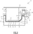
first surface area 20 and thesecond surface area 26 are pressed against one another with thesubstrate 14 and thecover sheet 16 between them in the molding position (figures 3 to 6 ). - The
first surface area 20 and thesecond surface area 26 are away from one another in the open position (figures 1 and2 ). - In the open position, the
first surface area 20 and thesecond surface area 26 are located one in front of the other. - The clamping
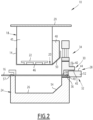
frame 28 comprises afirst clamping member 30, asecond clamping member 32 and a clampingdrive 34 moving the first clampingmember 30 and thesecond clamping member 32 with respect to one another between a cover sheet clamping position (figures 2 and3 ) and a cover sheet release position (figure 1 ). - An
edge 36 of thecover sheet 16 is clamped between the first clampingmember 30 and thesecond clamping member 32 in the clamping position. - The
edge 36 of thecover sheet 16 is free with respect to the first clampingmember 30 and/or thesecond clamping member 32 in the release position. - The
first clamping member 30 is a frame. - It has a substantially closed contour, and surrounds an empty space. It is arranged around the
first mold section 18, as shown on the figures. - The
second clamping member 32 has a substantially closed contour. It surrounds an empty space. It is arranged around thesecond surface area 26, as shown on the figures. - The
first clamping member 30 has afirst clamping surface 38. - The
second clamping member 32 has asecond clamping surface 40. - The
first clamping surface 30 and thesecond clamping surface 32 clamp theedge 36 of thecover sheet 16 between them in the clamping position (figure 2 ). - The
first clamping surface 30 is turned longitudinally in one direction, toward thesecond clamping section 24. Thesecond clamping surface 32 is turned longitudinally in the opposite direction. - When the
first mold section 18 and thesecond mold section 24 are in the open position, thecover sheet 16 extends between thefirst surface area 20 and thesecond surface area 26 in the clamping position of the clampingframe 30. - The clamping
drive 34 is typically a pneumatic or hydraulic cylinder or any other type of actuator. - The clamping
drive 34 moves the first clampingmember 30 longitudinally in translation with respect to thesecond clamping member 32. - The clamping
frame 28 is arranged for adjusting the clamping force by which theedge 36 of thecover sheet 16 is clamped between the first clampingmember 30 and thesecond clamping member 32 in the clamping position. - The clamping
frame 28 comprises for this purpose anadjustable stopper 42, able to adjust the spacing between thefirst clamping surface 38 and thesecond clamping surface 40 in the clamping position. - The
adjustable stopper 42 comprises for example one or several screws, mounted on the first clampingmember 30. The or each screw protrudes longitudinally with respect to alower surface 43 of the first clampingmember 30 turned tower thesecond clamping member 32. The height by which the or each screw protrudes is adjustable. In the clamping position, theadjustable stopper 42 is in abutment against anupper surface 44 of thesecond clamping member 32. - Changing the position of the screws with respect to the
lower surface 44 allows changing the longitudinal position of the first clampingmember 30 with respect to thesecond clamping member 32 in the clamping position, and thus the longitudinal position of thefirst clamping surface 38 with respect to thesecond clamping surface 40 in the clamping position. This in turn allows changing the longitudinal spacing between thefirst clamping surface 38 and thesecond clamping surface 40 in the clamping position. - The clamping force by which the
edge 36 of thecover sheet 16 is clamped between the first clampingmember 30 and thesecond clamping member 32 in the clamping position can be adjusted as well by changing the force applied by clampingdrive 34. - Another possibility for adjusting said clamping force is using supplements arranged between the clamping
drive 34 and the first clampingmember 30. A supplement is spacer having a reduced thickness, arranged between the piston of the cylinder and the first clampingmember 30, for example a washer or a plate. Adding or removing one or several supplements allows changing the longitudinal position of thefirst clamping surface 38 with respect to thesecond clamping surface 40 in the clamping position and thus the longitudinal spacing between thefirst clamping surface 38 and thesecond clamping surface 40. - The
first mold section 18 comprises amain part 45 defining amain area 46 of thefirst surface area 20, and at least onelongitudinal slider 48 movable with respect to themain part 44 between an extended position (figures 1 to 3 ) and a retracted position (figures 4 and5 ). - The at least one
longitudinal slider 48 is displaced with respect to themain part 44 by an actuator, not shown on the figures. The actuator is typically a cylinder, pneumatic or hydraulic. - The or each
longitudinal slider 48 defines a firstsurface edge area 50 of thefirst surface area 20 in the extended position. - The or each
longitudinal slider 48 is retracted longitudinally away from thefirst surface area 20 in the retracted position. - The or each
longitudinal slider 48 is for folding the edge of thecover sheet 16 around the free edge of thesubstrate 14, as will be described further down. - For that purpose, the
second clamping member 32 comprises at least onetransverse slider 52, movable with respect to thesecond mold section 24 between an outer position (figures 1 to 4 ) and an inner position (figure 5 ). - The or each
transverse slider 52 in the inner position extends longitudinally in front of the at least onelongitudinal slider 48 when thefirst mold section 18 is in the molding position with respect to thesecond mold section 24 and the at least onelongitudinal slider 48 is in the retracted position. - More specifically, when the
first mold section 18 is in the molding position with respect to thesecond mold section 24 and the at least onelongitudinal slider 48 is in the extended position, the firstsurface edge area 50 is pressed against a correspondingarea 54 of the second surface area 26 (figure 3 ). - When the
first mold section 18 is in the molding position with respect to thesecond mold section 24 and the at least onelongitudinal slider 48 is in the retracted position, acavity 56 is created in thefirst mold section 18 for receiving thetransverse slider 52 in the inner position (figure 5 ). - The or each
transverse slider 52 in the outer position does not extend longitudinally in front of the at least onelongitudinal slider 48. It does not extend, longitudinally, in front of thesecond surface area 26. - Advantageously, the or each
transverse slider 52 defines a part of thesecond clamping surface 40. - As shown on the figures, the
second surface area 26 is a depression, surrounded by anupper edge 57 having a closed contour. - Typically, a part of the
second clamping member 32 is made by at least one portion of theupper edge 57, and another part of thesecond clamping member 32 is made by the or eachtransverse slider 52. - A part of the
second clamping surface 40 is made by at least one portion of theupper edge 57, and another part of thesecond clamping surface 40 is made by the or eachtransverse slider 52. - For example, if the
second clamping member 32 comprises severaltransverse sliders 52, thesecond clamping member 32 comprises several portions of theupper edge 57, separated from one another by thetransverse sliders 52. - The process for producing the
trim panel 12 will be detailed below. - The process is designed for being implemented using the
apparatus 10 described above. Conversely, theapparatus 10 is particularly adapted for carrying out the process detailed below. - The process comprises the following steps:
- arranging the
substrate 14 against afirst surface area 20 of afirst mold section 18; - arranging the
cover sheet 16 in aclamping frame 28, anedge 36 of thecover sheet 16 being clamped between afirst clamping member 30 and asecond clamping member 32, thecover sheet 16 extending between thefirst surface area 20 and asecond surface area 26 of asecond mold section 24; - moving the
first mold section 18 and thesecond mold section 24 with respect to one another to a molding position, thefirst surface area 20 and thesecond surface area 26 being pressed against one another with thesubstrate 14 and thecover sheet 16 between them in the molding position. - The
main drive 29 moves thefirst mold section 18 with respect to thesecond mold section 24 longitudinally between the molding position and the open position. - The
first mold section 18 is as described above. - The clamping
frame 28, the first clampingmember 30 and thesecond clamping member 32 are as described above. - The step of arranging the
substrate 12 against thefirst surface area 20 and the step of arranging thecover sheet 16 in the clampingframe 28 are carried out with thefirst mold section 18 and thesecond mold section 24 in an open position with respect to one another. - The
first surface area 20 and thesecond surface area 26 are away from one another in the open position, as shown in thefigure 1 . - The
substrate 14 is arranged against thefirst surface area 20 by mean of a holdingdevice 22. The holdingdevice 22, as described above, is for example a vacuum device, or a mechanical clamping device. - The
cover sheet 16 is arranged in the clampingframe 28 as shown in thefigures 1 and2 . - The
first clamping member 30 and thesecond clamping member 32 are initially in a release position with respect to one another (figure 1 ). Thefirst clamping member 30 and thesecond clamping member 32 are longitudinally away from one another. - The
cover sheet 16 is secured to thesecond clamping member 32, for example using pins (not shown on the figures) arranged on thesecond clamping surface 40. - Then, the first clamping
member 30 and thesecond clamping member 32 are brought to a cover sheet clamping position with respect to one another (figure 2 ). - The
first clamping member 30 is moved longitudinally with respect to thesecond clamping member 32. - The
first clamping member 30 stops when theadjustable stopper 42 comes in abutment against theupper surface 44 of thesecond clamping member 32. - The
edge 36 of thecover sheet 14 is clamped between the first clampingmember 30 and thesecond clamping member 32 in the clamping position, and more specifically between thefirst clamping surface 38 and thesecond clamping surface 40. - The spacing between the
first clamping surface 38 and thesecond clamping surface 40 in the clamping position is adjusted by mean of theadjustable stopper 42. - It is adjusted as a function of the thickness of the
cover sheet 16, and of the clamping force by which theedge 36 of thecover sheet 16 must clamped between the first clampingmember 30 and thesecond clamping member 32. - The
adjustable stopper 42 is as described above. - In some cases, the
edge 36 of the cover sheet must be strongly clamped, such that the position of theedge 36 does not shift when thefirst molding section 18 and thesecond molding section 24 are brought to the molding position. In other instances, theedge 36 of the cover sheet must be less strongly clamped, such that the position of theedge 36 is allowed to shift when thefirst molding section 18 and thesecond molding section 24 are brought to the molding position. - Alternatively, or in addition, the clamping force is adjusted by changing the force applied by clamping
drive 34, and/or using supplements arranged between the clampingdrive 34 and the first clampingmember 30, as described above. - The molding position is shown on the
figure 3 . - The
substrate 14 and acentral part 58 of thecover sheet 16 are pinched between thefirst surface area 20 and thesecond area 26. Thecentral part 58 of thecover sheet 16 covers anouter surface 59 of thesubstrate 14. Theedge 36 of the cover sheet is clamped between the first clampingmember 30 and thesecond clamping member 32. - The
edge 36 is connected to thecentral part 58 by afolding line 60 along which thecover sheet 16 is folded. - The process further comprises the following additional steps:
- moving at least one
longitudinal slider 48 of thefirst mold section 18 with respect of amain part 45 of thefirst mold section 18 from an extended position (figures 1 to 3 ) to a retracted position (figures 4 and5 ), - folding the
edge 36 of thecover sheet 18 by moving at least onetransverse slider 52 of thesecond clamping member 32 from an outer position to an inner position. - The or each
longitudinal slider 48 is as described above. - As described above, the
main part 45 defines themain area 46 of thefirst surface area 20, the or eachlongitudinal slider 48 defining a firstsurface edge area 50 of thefirst surface area 20 in the extended position. - The or each
longitudinal slider 48 is retracted longitudinally away from thefirst surface area 20 in the retracted position. - The or each
transverse slide 52 is as described above. - As described above, the or each
transverse slider 52 in the inner position extends longitudinally in front of the at least onelongitudinal slider 48 when thefirst mold section 18 is in the molding position with respect to thesecond mold section 24 and the at least onelongitudinal slider 48 is in the retracted position. The or eachtransverse slider 52 in the outer position does not extend longitudinally in front of the at least onelongitudinal slider 48. - The situation at the end of the moving step is depicted on the
figure 4 . As shown, in the retracted position, acavity 56 is created on the side of thefirst mold section 18, in front of thetransverse slider 52. - Between the moving step and the folding step, the first clamping
member 30 and thesecond clamping member 32 are brought back to the release position with respect to one another (figure 5 ), to release theedge 36. - During the folding step, the or each
transverse slider 52 is moved substantially perpendicularly to the longitudinal direction L. The or eachtransverse slider 52 passes close to thefree edge 62 of thesubstrate 14. - At the beginning of the folding step, the
edge 36 of thecover sheet 16 extends on thesecond clamping surface 40. - When the or each
transverse slider 52 is moved from the outer position (figure 4 ) to the inner position (figure 5 ), theedge 36 is pivoted around thefolding line 60. - In the inner position, the
edge 36 extends longitudinally below the or eachtransverse slider 52. Below means against the surface of the or eachtransverse slider 52 opposite thesecond clamping surface 40. - The
edge 36 extends in thecavity 56. It extends between thefree edge 62 of thesubstrate 14 and the or eachtransverse slider 52. - The process further comprises the following additional steps:
- moving the at least one
transverse slider 52 of thesecond clamping member 32 back from the inner position to the outer position; - moving the at least one
longitudinal slider 48 of thefirst mold section 18 with respect of themain part 45 back from the retracted position (figure 5 ) to the extended position (figure 6 ). - During the displacement of the at least one
longitudinal slider 48 from the retracted position to the extended position, theedge 36 is folded around thefree edge 62 of the substrate. It is pressed against aninner surface 64 of thesubstrate 14. Theinner surface 64 is opposite theouter surface 59. - The
first mold section 18 and thesecond mold section 24 are then moved with respect one another to the open position, and thetrim part 12 is removed. - Alternative embodiments can be considered for the apparatus / process described above.
- The
first clamping member 30 and / or thesecond clamping member 32 do not necessarily have a substantially closed contour. It can be open along a part of its contour. - The number of transverse sliders and the positions of the transverse sliders are chosen as a function of the portions of the
free edge 62 of the substrate around which theedge 16 of the cover sheet must be folded. - The number of longitudinal sliders and the positions of the longitudinal sliders are chosen in consideration of the positions of the transverse sliders.
- The apparatus / process described above has significant advantages.
- Since the clamping frame is arranged for adjusting the clamping force by which the edge of the cover sheet is clamped between the first clamping member and the second clamping member in the clamping position, it is possible to control the displacement of the cover sheet when the main drive moves the first mold section and the second mold section with respect to one another to the molding position. This is particularly useful when the trim part comprises areas like curves or corners, where it is necessary to hold the cover sheet or to allow the edge to slide, depending on the properties of the material constituting the cover sheet.
- When the clamping frame comprises an adjustable stopper, able to adjust the spacing between the first clamping surface and the second clamping surface in the clamping position, the clamping force can be easily adjusted. The apparatus can be readily adapted to cover sheets having various thicknesses or made from various materials.
- When the first mold section comprises a main part defining a main area of the first surface area and at least one longitudinal slider movable with respect to the main part between an extended position and a retracted position, it becomes possible to laminate the cover sheet on the substrate and to fold the edge of the substrate in the same apparatus. In the state of the art, two different apparatus are frequently used to carry out these two operations. In the invention, the cover sheet is laminated on the substrate using both the main part and the at least one longitudinal slider. The at least one longitudinal slider is also used for folding the edge of the cover sheet. The apparatus is thus particularly compact.
- When the second clamping member comprises at least one transverse slider, movable with respect to the second mold section between an outer position and an inner position, the apparatus is particularly compact. The transverse slider is integrated in the clamping frame.
- When the or each transverse slider defines a part of the second clamping surface, the apparatus is particularly compact. The or each transverse slider are used both to clamp the cover sheet and to fold the edge of the cover sheet.
Claims (10)
- Apparatus for producing a trim panel (12) having at least a substrate (14) and a cover sheet (16) laminated to said substrate (14), the apparatus (10) comprising:- a first mold section (18), with a first surface area (20) and a holding device (22) holding the substrate (14) on the first surface area (20);- a second mold section (24), with a second surface area (26);- a clamping frame (28), with a first clamping member (30), a second clamping member (32) and a clamping drive (34) moving the first clamping member (30) and the second clamping member (32) with respect to one another between a cover sheet clamping position and a cover sheet release position, an edge (36) of the cover sheet (16) being clamped between the first clamping member (30) and the second clamping member (32) in the clamping position, the edge (36) of the cover sheet (16) being free with respect to the first clamping member (30) and/or the second clamping member (32) in the release position, the cover sheet (16) extending between the first surface area (20) and the second surface area (26) in the clamping position;- a main drive (29) moving the first mold section (18) and the second mold section (24) with respect to one another between a molding position and an open position, the first surface area (20) and the second surface area (26) being pressed against one another with the substrate (14) and the cover sheet (16) between them in the molding position, the first surface area (20) and the second surface area (26) being away from one another in the open position.
- The apparatus according to the claim 1, in which the clamping frame (28) is arranged for adjusting the clamping force by which the edge (36) of the cover sheet (16) is clamped between the first clamping member (30) and the second clamping member (32) in the clamping position.
- The apparatus according to the claim 1 or 2, in which the first clamping member (30) has a first clamping surface (38), the second clamping member (32) has a second clamping surface (40), the first clamping surface (38) and the second clamping surface (40) clamping the edge (36) of the cover sheet (16) between them in the clamping position.
- The apparatus according to the claim 3, in which the clamping frame (28) comprises an adjustable stopper (42), able to adjust the spacing between the first clamping surface (38) and the second clamping surface (40) in the clamping position.
- The apparatus according to anyone the claims 1 to 4, in which the main drive (29) moves the first mold section (18) with respect to the second mold section (24) longitudinally between the molding position and the open position, the first mold section (18) comprising a main part (45) defining a main area (46) of the first surface area (20) and at least one longitudinal slider (48) movable with respect to the main part (45) between an extended position and a retracted position, the or each longitudinal slider (48) defining a first surface edge area (50) of the first surface area (20) in the extended position, and the or each longitudinal slider (48) being retracted longitudinally away from the first surface area (20) in the retracted position.
- The apparatus according to the claim 5, in which the second clamping member (32) comprises at least one transverse slider (52), movable with respect to the second mold section (24) between an outer position and an inner position, wherein the or each transverse slider (52) in the inner position extends longitudinally in front of the at least one longitudinal slider (48) when the first mold section (18) is in the molding position with respect to the second mold section (24) and the at least one longitudinal slider (48) is in the retracted position, the or each transverse slider (52) in the outer position does not extend longitudinally in front of the at least one longitudinal slider (48).
- The apparatus according to the claim 6 and the claim 3 or 4, in which the or each transverse slider (52) defines a part of the second clamping surface (40).
- The apparatus according to the claim 6 or 7, in which:- when the first mold section (18) is in the molding position with respect to the second mold section (24) and the or each longitudinal slider (48) is in the extended position, the first surface edge area (50) is pressed against a corresponding area (54) of the second surface area (26);- when the first mold section (18) is in the molding position with respect to the second mold section (24) and the or each longitudinal slider (48) is in the retracted position, a cavity (56) is created in the first mold section (18) for receiving the at least one transverse slider (52) in the inner position.
- Process for producing a trim panel (10) having at least a substrate (14) and a cover sheet (16) laminated to said substrate (14), the process comprising the following steps:- arranging the substrate (14) against a first surface area (20) of a first mold section (18);- arranging the cover sheet (16) in a clamping frame (28), an edge (36) of the cover sheet (16) being clamped between a first clamping member (30) and a second clamping member (32), the cover sheet (16) extending between the first surface area (20) and a second surface area (26) of a second mold section (24);- moving the first mold section (18) and the second mold section (24) with respect to one another to a molding position, the first surface area (20) and the second surface area (26) being pressed against one another with the substrate (14) and the cover sheet (16) between them in the molding position.
- The process according to the claim 9, in which the process comprises the following additional steps:- moving at least one longitudinal slider (48) of the first mold section (18) with respect of a main part (45) of the first mold section (18) from an extended position to a retracted position, the main part (45) defining a main area (46) of the first surface area (20), the or each longitudinal slider (48) defining a first surface edge area (50) of the first surface area (20) in the extended position, the or each longitudinal slider (48) being retracted longitudinally away from the first surface area (20) in the retracted position,- folding the edge (36) of the cover sheet (16) by moving at least one transverse slider (52) of the second clamping member (32) from an outer position to an inner position, wherein the or each transverse slider (52) in the inner position extends longitudinally in front of the at least one longitudinal slider (48) when the first mold section (18) is in the molding position with respect to the second mold section (24) and the at least one longitudinal slider (48) is in the retracted position, the or each transverse slider (52) in the outer position does not extend longitudinally in front of the at least one longitudinal slider (48).
Priority Applications (1)
| Application Number | Priority Date | Filing Date | Title |
|---|---|---|---|
| EP22305517.9A EP4261010B1 (en) | 2022-04-11 | 2022-04-11 | Apparatus and process for producing a trim panel |
Applications Claiming Priority (1)
| Application Number | Priority Date | Filing Date | Title |
|---|---|---|---|
| EP22305517.9A EP4261010B1 (en) | 2022-04-11 | 2022-04-11 | Apparatus and process for producing a trim panel |
Publications (2)
| Publication Number | Publication Date |
|---|---|
| EP4261010A1 true EP4261010A1 (en) | 2023-10-18 |
| EP4261010B1 EP4261010B1 (en) | 2025-07-16 |
Family
ID=81648178
Family Applications (1)
| Application Number | Title | Priority Date | Filing Date |
|---|---|---|---|
| EP22305517.9A Active EP4261010B1 (en) | 2022-04-11 | 2022-04-11 | Apparatus and process for producing a trim panel |
Country Status (1)
| Country | Link |
|---|---|
| EP (1) | EP4261010B1 (en) |
Citations (8)
| Publication number | Priority date | Publication date | Assignee | Title |
|---|---|---|---|---|
| US5076880A (en) * | 1988-09-16 | 1991-12-31 | R + S Stanztechnik Gmbh | Apparatus for manufacturing trim panels including several trim components |
| JPH08258132A (en) * | 1995-03-18 | 1996-10-08 | Inoac Corp | Method and apparatus for laminating skin material |
| US5718791A (en) * | 1995-06-05 | 1998-02-17 | R + S Stanztechnik Gmbh | Method of laminating a trim panel and folding a cover sheet edge around the panel rim |
| JP2000033839A (en) * | 1998-04-24 | 2000-02-02 | Kodama Chemical Industry Co Ltd | Vehicle interior trim panel with foam layer with soft touch, method for manufacturing the panel, and apparatus for manufacturing the panel |
| US6524506B2 (en) * | 2000-12-26 | 2003-02-25 | R+S Technik Gmbh | Combination tool for edge-folding and cutting a panel rim |
| US20030155685A1 (en) * | 2002-02-15 | 2003-08-21 | R + S Technik Gmbh | Molding method and apparatus with plural cooperating mold tools for forming interior trim components for motor vehicles |
| US20160361837A1 (en) * | 2015-06-15 | 2016-12-15 | International Automotive Components Group North America, Inc. | Manufacture Of An Article Having A Decorative Cover Sheet Overlying A Substrate |
| KR102175880B1 (en) * | 2013-08-16 | 2020-11-06 | 닛샤 가부시키가이샤 | Die set, thermal forming device, thermal forming method, and thermally formed product |
-
2022
- 2022-04-11 EP EP22305517.9A patent/EP4261010B1/en active Active
Patent Citations (8)
| Publication number | Priority date | Publication date | Assignee | Title |
|---|---|---|---|---|
| US5076880A (en) * | 1988-09-16 | 1991-12-31 | R + S Stanztechnik Gmbh | Apparatus for manufacturing trim panels including several trim components |
| JPH08258132A (en) * | 1995-03-18 | 1996-10-08 | Inoac Corp | Method and apparatus for laminating skin material |
| US5718791A (en) * | 1995-06-05 | 1998-02-17 | R + S Stanztechnik Gmbh | Method of laminating a trim panel and folding a cover sheet edge around the panel rim |
| JP2000033839A (en) * | 1998-04-24 | 2000-02-02 | Kodama Chemical Industry Co Ltd | Vehicle interior trim panel with foam layer with soft touch, method for manufacturing the panel, and apparatus for manufacturing the panel |
| US6524506B2 (en) * | 2000-12-26 | 2003-02-25 | R+S Technik Gmbh | Combination tool for edge-folding and cutting a panel rim |
| US20030155685A1 (en) * | 2002-02-15 | 2003-08-21 | R + S Technik Gmbh | Molding method and apparatus with plural cooperating mold tools for forming interior trim components for motor vehicles |
| KR102175880B1 (en) * | 2013-08-16 | 2020-11-06 | 닛샤 가부시키가이샤 | Die set, thermal forming device, thermal forming method, and thermally formed product |
| US20160361837A1 (en) * | 2015-06-15 | 2016-12-15 | International Automotive Components Group North America, Inc. | Manufacture Of An Article Having A Decorative Cover Sheet Overlying A Substrate |
Also Published As
| Publication number | Publication date |
|---|---|
| EP4261010B1 (en) | 2025-07-16 |
Similar Documents
| Publication | Publication Date | Title |
|---|---|---|
| US5718791A (en) | Method of laminating a trim panel and folding a cover sheet edge around the panel rim | |
| EP0720902B1 (en) | Apparatus and method for moulding a multilayered trim component | |
| CN101874139B (en) | Method and apparatus for forming vehicle trim panels | |
| CN101873950B (en) | Vehicle panel | |
| US10000005B2 (en) | Article vacuum formation method and vacuum forming apparatus | |
| EP4261010A1 (en) | Apparatus and process for producing a trim panel | |
| JP4440555B2 (en) | Method and apparatus for producing decorative molded product | |
| US7371341B2 (en) | Method of forming a vehicle component | |
| CN101909846A (en) | Method and device for producing a molded part with a plurality of adjoining different decorative regions | |
| WO2009012313A1 (en) | Method of tensioning coverstock and forming vehicle interior components using retractable pins | |
| JP4525513B2 (en) | Manufacturing method of skin integral molding | |
| US20020044984A1 (en) | Injection molding apparatus for underlaying a top material with plastic | |
| JP5450032B2 (en) | Skin crimping method and crimping device | |
| EP3098046B1 (en) | Trim parts forming method and tools | |
| WO2009045202A1 (en) | Methods of tensioning coverstock and forming vehicle interior components | |
| KR100688926B1 (en) | Manufacturing apparatus and method for automobile interior panel, and automobile interior panel manufactured by the method | |
| CN118003559A (en) | Device and method for manufacturing skin-integrated built-in material | |
| EP3473409B1 (en) | Method and device for producing an edgefold | |
| KR102372824B1 (en) | Apparatus for forming skin of crash pad | |
| US5851569A (en) | Cold edge folding apparatus for making door inserts for automobile doors | |
| JP3745933B2 (en) | Method for forming laminated molded body | |
| US20250242526A1 (en) | Vehicle interior panel with reinforcing layer and related method | |
| JPH04341823A (en) | Pressure contacting method and pressure contacting device of decorative sheet in trim parts for automobile | |
| JP4318158B2 (en) | Method and apparatus for molding laminated molded body | |
| US20240025351A1 (en) | Holding apparatus and method for holding a mobile device |
Legal Events
| Date | Code | Title | Description |
|---|---|---|---|
| PUAI | Public reference made under article 153(3) epc to a published international application that has entered the european phase |
Free format text: ORIGINAL CODE: 0009012 |
|
| STAA | Information on the status of an ep patent application or granted ep patent |
Free format text: STATUS: THE APPLICATION HAS BEEN PUBLISHED |
|
| AK | Designated contracting states |
Kind code of ref document: A1 Designated state(s): AL AT BE BG CH CY CZ DE DK EE ES FI FR GB GR HR HU IE IS IT LI LT LU LV MC MK MT NL NO PL PT RO RS SE SI SK SM TR |
|
| STAA | Information on the status of an ep patent application or granted ep patent |
Free format text: STATUS: REQUEST FOR EXAMINATION WAS MADE |
|
| 17P | Request for examination filed |
Effective date: 20240320 |
|
| RBV | Designated contracting states (corrected) |
Designated state(s): AL AT BE BG CH CY CZ DE DK EE ES FI FR GB GR HR HU IE IS IT LI LT LU LV MC MK MT NL NO PL PT RO RS SE SI SK SM TR |
|
| GRAP | Despatch of communication of intention to grant a patent |
Free format text: ORIGINAL CODE: EPIDOSNIGR1 |
|
| STAA | Information on the status of an ep patent application or granted ep patent |
Free format text: STATUS: GRANT OF PATENT IS INTENDED |
|
| RIC1 | Information provided on ipc code assigned before grant |
Ipc: B29L 31/30 20060101ALN20250319BHEP Ipc: B29C 51/08 20060101ALN20250319BHEP Ipc: B29C 51/26 20060101ALI20250319BHEP Ipc: B29C 51/16 20060101AFI20250319BHEP |
|
| INTG | Intention to grant announced |
Effective date: 20250327 |
|
| GRAS | Grant fee paid |
Free format text: ORIGINAL CODE: EPIDOSNIGR3 |
|
| GRAA | (expected) grant |
Free format text: ORIGINAL CODE: 0009210 |
|
| STAA | Information on the status of an ep patent application or granted ep patent |
Free format text: STATUS: THE PATENT HAS BEEN GRANTED |
|
| AK | Designated contracting states |
Kind code of ref document: B1 Designated state(s): AL AT BE BG CH CY CZ DE DK EE ES FI FR GB GR HR HU IE IS IT LI LT LU LV MC MK MT NL NO PL PT RO RS SE SI SK SM TR |
|
| REG | Reference to a national code |
Ref country code: GB Ref legal event code: FG4D |
|
| REG | Reference to a national code |
Ref country code: CH Ref legal event code: EP |
|
| REG | Reference to a national code |
Ref country code: DE Ref legal event code: R096 Ref document number: 602022017637 Country of ref document: DE |
|
| REG | Reference to a national code |
Ref country code: IE Ref legal event code: FG4D |
|
| REG | Reference to a national code |
Ref country code: NL Ref legal event code: MP Effective date: 20250716 |
|
| PG25 | Lapsed in a contracting state [announced via postgrant information from national office to epo] |
Ref country code: PT Free format text: LAPSE BECAUSE OF FAILURE TO SUBMIT A TRANSLATION OF THE DESCRIPTION OR TO PAY THE FEE WITHIN THE PRESCRIBED TIME-LIMIT Effective date: 20251117 |
|
| PG25 | Lapsed in a contracting state [announced via postgrant information from national office to epo] |
Ref country code: NL Free format text: LAPSE BECAUSE OF FAILURE TO SUBMIT A TRANSLATION OF THE DESCRIPTION OR TO PAY THE FEE WITHIN THE PRESCRIBED TIME-LIMIT Effective date: 20250716 |
|
| PG25 | Lapsed in a contracting state [announced via postgrant information from national office to epo] |
Ref country code: IS Free format text: LAPSE BECAUSE OF FAILURE TO SUBMIT A TRANSLATION OF THE DESCRIPTION OR TO PAY THE FEE WITHIN THE PRESCRIBED TIME-LIMIT Effective date: 20251116 |
|
| PG25 | Lapsed in a contracting state [announced via postgrant information from national office to epo] |
Ref country code: NO Free format text: LAPSE BECAUSE OF FAILURE TO SUBMIT A TRANSLATION OF THE DESCRIPTION OR TO PAY THE FEE WITHIN THE PRESCRIBED TIME-LIMIT Effective date: 20251016 |
|
| REG | Reference to a national code |
Ref country code: LT Ref legal event code: MG9D |
|
| PG25 | Lapsed in a contracting state [announced via postgrant information from national office to epo] |
Ref country code: FI Free format text: LAPSE BECAUSE OF FAILURE TO SUBMIT A TRANSLATION OF THE DESCRIPTION OR TO PAY THE FEE WITHIN THE PRESCRIBED TIME-LIMIT Effective date: 20250716 |
|
| PG25 | Lapsed in a contracting state [announced via postgrant information from national office to epo] |
Ref country code: HR Free format text: LAPSE BECAUSE OF FAILURE TO SUBMIT A TRANSLATION OF THE DESCRIPTION OR TO PAY THE FEE WITHIN THE PRESCRIBED TIME-LIMIT Effective date: 20250716 |
|
| PG25 | Lapsed in a contracting state [announced via postgrant information from national office to epo] |
Ref country code: GR Free format text: LAPSE BECAUSE OF FAILURE TO SUBMIT A TRANSLATION OF THE DESCRIPTION OR TO PAY THE FEE WITHIN THE PRESCRIBED TIME-LIMIT Effective date: 20251017 |
|
| PG25 | Lapsed in a contracting state [announced via postgrant information from national office to epo] |
Ref country code: SE Free format text: LAPSE BECAUSE OF FAILURE TO SUBMIT A TRANSLATION OF THE DESCRIPTION OR TO PAY THE FEE WITHIN THE PRESCRIBED TIME-LIMIT Effective date: 20250716 |
|
| PG25 | Lapsed in a contracting state [announced via postgrant information from national office to epo] |
Ref country code: LV Free format text: LAPSE BECAUSE OF FAILURE TO SUBMIT A TRANSLATION OF THE DESCRIPTION OR TO PAY THE FEE WITHIN THE PRESCRIBED TIME-LIMIT Effective date: 20250716 |
|
| PG25 | Lapsed in a contracting state [announced via postgrant information from national office to epo] |
Ref country code: PL Free format text: LAPSE BECAUSE OF FAILURE TO SUBMIT A TRANSLATION OF THE DESCRIPTION OR TO PAY THE FEE WITHIN THE PRESCRIBED TIME-LIMIT Effective date: 20250716 Ref country code: BG Free format text: LAPSE BECAUSE OF FAILURE TO SUBMIT A TRANSLATION OF THE DESCRIPTION OR TO PAY THE FEE WITHIN THE PRESCRIBED TIME-LIMIT Effective date: 20250716 |
|
| PG25 | Lapsed in a contracting state [announced via postgrant information from national office to epo] |
Ref country code: RS Free format text: LAPSE BECAUSE OF FAILURE TO SUBMIT A TRANSLATION OF THE DESCRIPTION OR TO PAY THE FEE WITHIN THE PRESCRIBED TIME-LIMIT Effective date: 20251016 |
|
| PG25 | Lapsed in a contracting state [announced via postgrant information from national office to epo] |
Ref country code: ES Free format text: LAPSE BECAUSE OF FAILURE TO SUBMIT A TRANSLATION OF THE DESCRIPTION OR TO PAY THE FEE WITHIN THE PRESCRIBED TIME-LIMIT Effective date: 20250716 |
|
| PG25 | Lapsed in a contracting state [announced via postgrant information from national office to epo] |
Ref country code: SM Free format text: LAPSE BECAUSE OF FAILURE TO SUBMIT A TRANSLATION OF THE DESCRIPTION OR TO PAY THE FEE WITHIN THE PRESCRIBED TIME-LIMIT Effective date: 20250716 |
|
| PG25 | Lapsed in a contracting state [announced via postgrant information from national office to epo] |
Ref country code: DK Free format text: LAPSE BECAUSE OF FAILURE TO SUBMIT A TRANSLATION OF THE DESCRIPTION OR TO PAY THE FEE WITHIN THE PRESCRIBED TIME-LIMIT Effective date: 20250716 |
|
| PGFP | Annual fee paid to national office [announced via postgrant information from national office to epo] |
Ref country code: IT Payment date: 20260319 Year of fee payment: 5 |
|
| PG25 | Lapsed in a contracting state [announced via postgrant information from national office to epo] |
Ref country code: CZ Free format text: LAPSE BECAUSE OF FAILURE TO SUBMIT A TRANSLATION OF THE DESCRIPTION OR TO PAY THE FEE WITHIN THE PRESCRIBED TIME-LIMIT Effective date: 20250716 |
|
| PG25 | Lapsed in a contracting state [announced via postgrant information from national office to epo] |
Ref country code: EE Free format text: LAPSE BECAUSE OF FAILURE TO SUBMIT A TRANSLATION OF THE DESCRIPTION OR TO PAY THE FEE WITHIN THE PRESCRIBED TIME-LIMIT Effective date: 20250716 Ref country code: SK Free format text: LAPSE BECAUSE OF FAILURE TO SUBMIT A TRANSLATION OF THE DESCRIPTION OR TO PAY THE FEE WITHIN THE PRESCRIBED TIME-LIMIT Effective date: 20250716 |