EP4260695B1 - Wave transmission control device, underwater organism guidance device, and wave transmission control method - Google Patents
Wave transmission control device, underwater organism guidance device, and wave transmission control method Download PDFInfo
- Publication number
- EP4260695B1 EP4260695B1 EP21917425.7A EP21917425A EP4260695B1 EP 4260695 B1 EP4260695 B1 EP 4260695B1 EP 21917425 A EP21917425 A EP 21917425A EP 4260695 B1 EP4260695 B1 EP 4260695B1
- Authority
- EP
- European Patent Office
- Prior art keywords
- sound
- transmission control
- underwater organism
- underwater
- transmitter
- Prior art date
- Legal status (The legal status is an assumption and is not a legal conclusion. Google has not performed a legal analysis and makes no representation as to the accuracy of the status listed.)
- Active
Links
Images



Classifications
-
- A—HUMAN NECESSITIES
- A01—AGRICULTURE; FORESTRY; ANIMAL HUSBANDRY; HUNTING; TRAPPING; FISHING
- A01K—ANIMAL HUSBANDRY; AVICULTURE; APICULTURE; PISCICULTURE; FISHING; REARING OR BREEDING ANIMALS, NOT OTHERWISE PROVIDED FOR; NEW BREEDS OF ANIMALS
- A01K61/00—Culture of aquatic animals
- A01K61/90—Sorting, grading, counting or marking live aquatic animals, e.g. sex determination
-
- A—HUMAN NECESSITIES
- A01—AGRICULTURE; FORESTRY; ANIMAL HUSBANDRY; HUNTING; TRAPPING; FISHING
- A01K—ANIMAL HUSBANDRY; AVICULTURE; APICULTURE; PISCICULTURE; FISHING; REARING OR BREEDING ANIMALS, NOT OTHERWISE PROVIDED FOR; NEW BREEDS OF ANIMALS
- A01K79/00—Methods or means of catching fish in bulk not provided for in groups A01K69/00 - A01K77/00, e.g. fish pumps; Detection of fish; Whale fishery
- A01K79/02—Methods or means of catching fish in bulk not provided for in groups A01K69/00 - A01K77/00, e.g. fish pumps; Detection of fish; Whale fishery by electrocution
-
- A—HUMAN NECESSITIES
- A01—AGRICULTURE; FORESTRY; ANIMAL HUSBANDRY; HUNTING; TRAPPING; FISHING
- A01M—CATCHING, TRAPPING OR SCARING OF ANIMALS; APPARATUS FOR THE DESTRUCTION OF NOXIOUS ANIMALS OR NOXIOUS PLANTS
- A01M29/00—Scaring or repelling devices, e.g. bird-scaring apparatus
- A01M29/16—Scaring or repelling devices, e.g. bird-scaring apparatus using sound waves
-
- A—HUMAN NECESSITIES
- A01—AGRICULTURE; FORESTRY; ANIMAL HUSBANDRY; HUNTING; TRAPPING; FISHING
- A01M—CATCHING, TRAPPING OR SCARING OF ANIMALS; APPARATUS FOR THE DESTRUCTION OF NOXIOUS ANIMALS OR NOXIOUS PLANTS
- A01M29/00—Scaring or repelling devices, e.g. bird-scaring apparatus
- A01M29/16—Scaring or repelling devices, e.g. bird-scaring apparatus using sound waves
- A01M29/18—Scaring or repelling devices, e.g. bird-scaring apparatus using sound waves using ultrasonic signals
-
- Y—GENERAL TAGGING OF NEW TECHNOLOGICAL DEVELOPMENTS; GENERAL TAGGING OF CROSS-SECTIONAL TECHNOLOGIES SPANNING OVER SEVERAL SECTIONS OF THE IPC; TECHNICAL SUBJECTS COVERED BY FORMER USPC CROSS-REFERENCE ART COLLECTIONS [XRACs] AND DIGESTS
- Y02—TECHNOLOGIES OR APPLICATIONS FOR MITIGATION OR ADAPTATION AGAINST CLIMATE CHANGE
- Y02A—TECHNOLOGIES FOR ADAPTATION TO CLIMATE CHANGE
- Y02A40/00—Adaptation technologies in agriculture, forestry, livestock or agroalimentary production
- Y02A40/80—Adaptation technologies in agriculture, forestry, livestock or agroalimentary production in fisheries management
- Y02A40/81—Aquaculture, e.g. of fish
Definitions
- the present disclosure relates to a wave transmission control device that outputs sound waves for moving organisms in water.
- Patent Literature 1 discloses a crustacean plankton catching method in which a group of crustacean plankton in the sea is moved. Specifically, when a group of crustacean plankton swimming in the sea is found by a fish detection device, sound wave generators are arranged in the sea so as to surround the group. When moving the group, the sound wave generators sequentially transmit a sound from the sound wave generator disposed below the group to the sound wave generator disposed above the group while detecting the position of the group, and move the group toward the sea surface.
- Patent Literature 2 discloses acoustic devices, attached to fishing nets, which emit a deterrent signal to a particular marine animal on actuation by the approach of the animal.
- Patent Literature 3 discloses a programmable, customizable system, method, and apparatus for attracting and stimulating aquatic animals.
- Patent Literature 4 discloses a device for modifying the behavior of fish, causing them to swim along a desired path, wherein the device projects sequences of sound into the water, resulting in sound wave patterns which direct the fish along the desired path.
- Patent Literature 5 discloses a device having a sound acquisition unit for acquiring sound to be outputted by a transmitter and a sound-field formation control unit for determining a range in which a sound-field is formed in water and for causing the transmitter to output the sound acquired by the sound acquisition unit to the determined range.
- Patent Literature 1 In a case where the crustacean plankton catching method described in Patent Literature 1 is applied to the case where a plurality of underwater organisms with different characteristics are mixed, it is not possible to sort and guide the underwater organisms, and the problem still cannot be solved.
- the present disclosure has been made to solve the above problems, and an object of the present disclosure is to provide a wave transmission control device that sorts and guides underwater organisms based on each characteristic even in a case where a plurality of organisms with different characteristics are mixed in water.
- a wave transmission control device performs control of a transmitter to form a sound field in water, the wave transmission control device including: a determination unit to, when detection information is input from a sensor to detect an organism in water, perform determination of a characteristic of the organism among a plurality of characteristics and a distribution state for said characteristic using the detection information; a sound selection unit to acquire sound information based on the characteristic determined by the determination unit by referring to a database in which the plurality of characteristics and a plural pieces of sound information are respectively associated with each other; and a wave-transmission control unit to determine a sound output condition in such a manner that a distribution state changes from the distribution state determined by the determination unit to a set distribution state which is set for each of the plurality of characteristics received before processing starts and to cause the transmitter to output a sound based on the sound information acquired by the sound selection unit using the sound output condition
- underwater organisms include all organisms in water.
- underwater includes a benthic region.
- sound or sound waves are used in the present disclosure.
- the sound or sound waves include frequencies below the human audible range and frequencies above the human audible range (ultrasound waves).
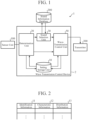
- FIG. 1 is a diagram illustrating an example of a configuration of an underwater organism guidance device and a wave transmission control device according to the present disclosure.
- An underwater organism guidance device 1 guides underwater organisms in such a manner that a desired distribution is obtained for each characteristic of underwater organisms. In a case where a plurality of organisms with different characteristics are mixed in water, the underwater organism guidance device 1 guides at least one type of fish as a guidance target using a sound and sorts the fish from other types of fish.
- the underwater organism guidance device 1 is assumed to be used for guiding one type of fish in the direction of a fishing net when fishing is performed in the sea.
- the underwater organism guidance device 1 is assumed to be used, for example, for guiding adult fish in the direction of a fishing net, keeping juvenile fish away from the fishing net, and preventing overfishing of the juvenile fish.
- the underwater organism guidance device 1 is assumed to be used, for example, for feeding small fish with a body length less than a threshold after keeping large fish with a body length larger than or equal to the threshold away from a feeding position when feeding the fish in an aquaculture farm.
- the underwater organism guidance device 1 is assumed to be used, for example, for separately guiding specific types of fish in a water tank of an aquarium.
- the underwater organism guidance device 1 illustrated in FIG. 1 includes a wave transmission control device 2, a sensor unit 100, a sound information database 200, and a transmitter 300.
- the wave transmission control device 2 the sensor unit 100, the sound information database 200, and the transmitter 300 are communicably connected to each other.
- the wave transmission control device 2 selects sound information with reference to the sound information database 200 by using detection information from the sensor unit 100 and distribution information indicating a distribution state being a guidance target, determines a sound output condition, and controls the transmitter 300 by using the output condition to form a sound field in water. Details of the wave transmission control device 2 and the sound information database 200 will be described later.
- the sensor unit 100 detects underwater organisms and outputs detection information.
- the sensor unit 100 detects underwater organisms using, for example, a sound wave, a radio wave, or light, and outputs detection information.
- the sensor unit 100 detects underwater organisms using, for example, an image captured by a camera, and outputs detection information.
- the sensor unit 100 may detect underwater organisms using two or more of a sound wave, a radio wave, light, and an image captured by a camera, and output the detection information.
- the transmitter 300 is provided in water.
- the transmitter 300 is attached to the hull of a ship, for example.
- the transmitter 300 is attached to a structure provided in, for example, the ocean, a river, or a water tank.
- the structure includes a structure floating on the water in addition to a structure fixed to a shore or a benthic region.
- the transmitter 300 outputs directional sound waves into water to form a sound field in the water.
- the transmitter 300 is, for example, a speaker, and is specifically an underwater speaker, a superdirectional speaker, an ultrasonic speaker, or an ultrasonic sensor.
- the transmitter 300 may be a speaker array including a plurality of any of the above and arranged in an array. That is, the transmitter includes, for example, one or a plurality of speakers.
- the transmitter 300 may output directional sound waves in a plurality of different directions in water.
- the transmitter 300 may include a drive unit (not illustrated) that changes a direction in which the transmitter 300 transmits waves in accordance with an output direction included in the output condition determined by a wave-transmission control unit 50.
- the drive unit when receiving a control signal from the wave-transmission control unit 50, the drive unit mechanically changes the direction of the transmitter 300 in accordance with the output direction indicated by the control signal.
- the wave-transmission control unit 50 can further cause the transmitter 300 to form a sound field in any direction in water and in any range in water.
- the wave-transmission control unit 50 controls the amplitude and phase of a sound output from each of the transmitters 300.
- the transmitter 300 can transmit waves, it is possible to cause the transmitter 300 to form a sound field in any direction in water and in any range in water.
- the wave transmission control device 2 illustrated in FIG. 1 includes a setting storage unit 10, a determination unit 20, a sound selection unit 30, and the wave-transmission control unit 50.
- the wave transmission control device 2 includes a control unit (not illustrated).
- the control unit issues a command to start, continue, and end the entire processing of the wave transmission control device 2 on the basis of information acquired from the inside and the outside of the wave transmission control device 2. For example, the control unit determines whether or not to end wave transmission control each time the wave transmission control device 2 executes control on the transmitter 300. When determining to end the wave transmission control, the control unit ends the processing performed by the wave transmission control device 2. When determining not to end the wave transmission control, the control unit issues a command to repeat the processing related to the wave transmission control from the beginning. When repeating the processing related to the wave transmission control, the control unit may issue a command to omit the processing performed by the sound selection unit 30 in the second and subsequent processing.
- the setting storage unit 10 stores a distribution state for each characteristic set in advance. Specifically, the setting storage unit 10 stores in advance information indicating characteristics of an underwater organism and information indicating a distribution state of the underwater organism in water before the wave transmission control device 2 starts wave transmission control processing on the transmitter 300.
- the information indicating the characteristics of the underwater organism and the information indicating the distribution state of the underwater organism in water are, for example, information set by a user before the wave transmission control device 2 starts the control processing.
- the information stored in the setting storage unit 10 indicates the distribution state in water of each underwater organism (guidance target) that the user desires to guide. It is only required that this information is received and stored at the latest until immediately before the wave transmission control device 2 starts control.
- FIG. 2 is a diagram illustrating an example of information stored in the setting storage unit 10.
- the setting storage unit 10 stores identification information 11, characteristic information 12, and distribution information 13 in association with one another.
- the setting storage unit 10 may store a plurality of sets of the identification information 11, the characteristic information 12, and the distribution information 13.
- the identification information 11 in the setting storage unit 10 is information for identifying a combination of the characteristic information 12 and the distribution information 13 in a case where a plurality of sets of the characteristic information 12 and the distribution information 13 are stored in the setting storage unit 10.
- the identification information 11 is, for example, alphanumeric characters that do not overlap in combinations of the characteristic information 12 and the distribution information 13.
- the characteristic information 12 in the setting storage unit 10 indicates characteristics of the underwater organism set in advance.
- the characteristic information 12 is, for example, at least one of information indicating the type of the underwater organism or information indicating the size of the underwater organism.
- the distribution information 13 indicates the distribution state of the underwater organism in water.
- the distribution information 13 indicates, for example, at least one of a direction of a region in water, a distance to the region, or a position of the region based on an installation position of the transmitter 300. Furthermore, the distribution information 13 may include the area of the region.
- the identification information 11 set in the setting storage unit 10 may be referred to as “set identification information 11", and similarly, the characteristic information 12 may be referred to as “set characteristic information 12", and the distribution information 13 may be referred to as “set distribution information 13".
- the distribution state indicated by the set distribution information 13 may be referred to as "set distribution state”.
- the set identification information 11 is not essential.
- FIG. 3 is a concept diagram illustrating an example of a distribution state set in the wave transmission control device 2.
- the setting storage unit 10 stores set distribution information 13 indicating a distribution state where fish 510a are present in a region 13a on the right front of the transmitter, and stores set distribution information 13 indicating a distribution state where fish 510b are present in a region 13b on the left front of the transmitter.
- the fish 510a and the fish 510b are different types of fish, and have different audible sounds from each other, or have different preference sounds and repellent sounds from each other.
- the determination unit 20 determines the characteristics of the underwater organism and the distribution state of the underwater organism for said characteristic using the detection information.
- the determination unit 20 outputs the characteristic information indicating the characteristic of the underwater organism and the distribution information indicating the distribution state of the organism for each characteristic.
- FIG. 4 is a diagram illustrating a configuration of the determination unit 20 in the wave transmission control device 2.
- FIG. 4 illustrates the configuration of the determination unit 20 and a relationship with peripheral components.
- the determination unit 20 illustrated in FIG. 4 includes a characteristic determination unit 21, a distribution determination unit 22, and a guidance determination unit 23.
- the characteristic determination unit 21 determines the characteristic of the underwater organism detected by the sensor unit 100 using the detection information received from the sensor unit 100.
- the characteristic of the underwater organism is, for example, the type, size, or degree of growth of the underwater organism.
- the technique of determining the type, size, or degree of growth of the underwater organism using the detection information from the sensor unit 100 can be implemented using a known technique. Therefore, detailed description is omitted here.
- the characteristic determination unit 21 outputs characteristic information indicating the determined characteristic.
- the characteristic information output by the characteristic determination unit 21 may be referred to as "determined characteristic information”.
- the distribution determination unit 22 determines the distribution state of the underwater organism detected by the sensor unit 100 using the detection information received from the sensor unit 100.
- the distribution determination unit 22 outputs distribution information indicating the determined distribution state.
- the distribution information determined by the distribution determination unit 22 indicates a region where the underwater organism is currently present. Specifically, the distribution information determined by the distribution determination unit 22 indicates any one of the direction of the region in water, the distance to the region, and the position of the region based on the installation position of the transmitter 300. In addition thereto, information indicating the area of the region may be included.
- the distribution information output by the distribution determination unit 22 may be referred to as "determined distribution information".
- the guidance determination unit 23 determines whether to execute wave transmission control for guiding the underwater organism.
- the guidance determination unit 23 refers to the setting storage unit 10 and determines whether or not the determined characteristic information received from the characteristic determination unit 21 matches the set characteristic information 12. As a result, when determining that they match, the guidance determination unit 23 can determine that the underwater organism detected by the sensor unit 100 is the underwater organism to be guided.
- the guidance determination unit 23 refers to the setting storage unit 10 and determines whether or not the determined distribution information received from the distribution determination unit 22 matches the set distribution information 13. As a result, when determining that they match, the guidance determination unit 23 can determine that the wave transmission control is executed to guide the underwater organism.
- the guidance determination unit 23 When determining that the wave transmission control is executed, the guidance determination unit 23 outputs the determined characteristic information and the determined distribution information.
- the guidance determination unit 23 may determine that the wave transmission control is not executed, and when determining that the difference exceeds the threshold, the guidance determination unit may determine that the wave transmission control is executed.
- the sound selection unit 30 refers to the sound information database 200 in which the characteristic of the underwater organism and the sound information are associated, and acquires sound information based on the characteristic determined by the determination unit 20. Specifically, the sound selection unit 30 refers to the sound information database 200 to search for characteristic information matching the determined characteristic information, and selects and acquires sound information associated with the searched characteristic information. The sound selection unit 30 outputs the acquired sound information.
- FIG. 5 is a diagram illustrating an example of information stored in the sound information database 200 used in the underwater organism guidance device 1.
- the sound information database 200 stores identification information 201, characteristic information 202, and sound information 203 in association with one another.
- the identification information 201 in the sound information database 200 is information for identifying a combination of the characteristic information 202 and the sound information 203.
- the identification information 201 includes, for example, alphabetical character strings or the like that are different for each pieces of set information.
- the characteristic information 202 in the sound information database 200 indicates characteristics of the underwater organism.
- the characteristic information 202 is, for example, type information indicating the type of the underwater organism or size information indicating the size of the underwater organism.
- the type information is fish name information such as "sardine” or “sea bream”
- the size information is information indicating a body length such as "10 cm”, or "adult fish” or “juvenile fish” based on the body length.
- the characteristic information 202 may be a value indicating the degree of growth of the underwater organism.
- the characteristic information 202 may be information indicating the combination of the type information and the size information.
- the sound information 203 in the sound information database 200 indicates an audible sound based on the auditory characteristic of each underwater organism.
- the sound information 203 indicates, for example, a frequency band and a wave transmission pattern in which the intensity of a sound changes with time.
- the auditory sense of underwater organisms will be described by taking fish as an example.
- the fish have auditory characteristics, and for example, the audible range varies depending on the type and size of the fish. That is, there is an audible sound corresponding to the type and size of fish.
- a predation sound generated at the time of preying on bait is a preference sound
- a barking sound generated against an action of a natural enemy is a repellent sound
- a feeding sound generated when a feeder operates is a preference sound
- a sound that fish has intentionally trained to avoid is a repellent sound.
- a method of intentionally training fish to avoid there is a method of training the fish by repeating a series of processes of vibrating water immediately after generating a certain sound and causing the fish to move away from the current position.
- Information indicating these preference sound and repellent sound is set as the sound information 203 in the sound information database 200.
- the sound type information capable of identifying that the sound is the preference sound or the repellent sound is further given to each combination of the characteristic information 202 and the sound information 203.
- the wave-transmission control unit 50 determines a sound output condition, the sound type information is used, for example, in processing of determining a direction in which the underwater organism is to be guided as the output direction in a case where the sound type information indicates the preference sound, and in processing of determining a direction opposite to the direction in which the underwater organism is to be guided as the output direction in a case where the sound type information indicates the repellent sound.
- the preference sound and the repellent sound can be used for processing in which both sounds are used in combination.
- the preference sound of the fish species A to be caught is selected, the preference sound of the fish species A is output to a desired position, and the fish species A is guided to a catch position.
- the repellent sound of the underwater organisms other than the fish species A is output to the position where the preference sound of the fish species A is output to move the underwater organisms other than the fish species A away from the catch position.
- the sound information 203 in the sound information database 200 may be only the preference sound or only the repellent sound.
- the sound information database 200 is configured to be included in the underwater organism guidance device 1 and is provided outside the wave transmission control device 2, but is not limited thereto.
- the sound information database 200 may be, for example, a database outside the underwater organism guidance device 1, and the sound information database 200 may be provided inside the wave transmission control device 2, for example.
- the sound information database 200 may be provided in a cloud or the like that can be referred to by the underwater organism guidance device 1, or may be provided in a portable storage medium such as an SD card.
- the sound information database is only required to be communicably connected to the wave transmission control device 2.
- the wave-transmission control unit 50 illustrated in FIG. 1 determines a sound output condition so as to guide an underwater organism to be guided to a region to be guided, and executes control to cause the transmitter 300 to output a sound using the output condition.
- the wave-transmission control unit 50 determines a sound output condition so as to obtain a distribution state (a distribution state indicated by set distribution information) for each characteristic set in advance in the setting storage unit 10, and causes the transmitter 300 to output a sound based on the sound information acquired by the sound selection unit 30 in such a manner that the determined output condition is satisfied.
- the wave-transmission control unit 50 repeats processing of determining a sound output condition and causing the transmitter 300 to output a sound based on the sound information acquired by the sound selection unit 30 in such a manner that the determined output condition is satisfied until the distribution state changes from the distribution state determined by the determination unit 20 to the distribution state indicated by the set distribution information.
- FIG. 6 is a diagram illustrating a configuration of the wave-transmission control unit 50 in the wave transmission control device 2.
- FIG. 6 illustrates the configuration of the wave-transmission control unit 50 and a relationship with peripheral components.
- the wave-transmission control unit 50 illustrated in FIG. 6 includes a distribution estimation unit 51, an output-direction determination unit 52, and a control-signal generation unit 53.
- the output-direction determination unit 52 is an example of an output-condition determination unit that determines a sound output condition.
- the distribution estimation unit 51 compares the distribution state determined by the determination unit 20 with the distribution state indicated by the set distribution information, and estimates a distribution state where the distribution state determined by the determination unit 20 becomes closer to the distribution state indicated by the set distribution information.
- the distribution estimation unit 51 compares the determined distribution information with the set distribution information for each characteristic stored in the setting storage unit 10. The distribution estimation unit 51 estimates a distribution state where the distribution state indicated by the determined distribution information becomes closer to the distribution state indicated by the set distribution information.
- the method of estimating the distribution state where the current distribution state is brought close to the distribution state for each characteristic set in advance can be implemented by a known technique such as artificial intelligence (AI).
- AI artificial intelligence
- it can be implemented by changing the distance between the coordinates of two different distributions so as to gradually decrease. Therefore, a more detailed description will be omitted.
- the distribution estimation unit 51 outputs distribution information indicating the estimated distribution state. Specifically, the distribution information output from the distribution estimation unit 51 indicates any one of the direction of the region in water, the distance to the region, and the position of the region based on the installation position of the transmitter 300. In addition thereto, information indicating the area of the region may be included. Hereinafter, the distribution information output by the distribution estimation unit 51 may be referred to as "estimated distribution information".
- the output-direction determination unit 52 determines a sound output direction in such a manner that the distribution state estimated by the distribution estimation unit 51 is obtained.
- the output-direction determination unit 52 determines the direction indicated by the estimated distribution information as the output direction. Furthermore, for example, in a case where the repellent sound is output, the output-direction determination unit 52 determines the direction opposite to the direction indicated by the estimated distribution information as the output direction with respect to the region indicated by the determined distribution information.
- the output-direction determination unit 52 outputs output direction information indicating the determined output direction.
- the output-direction determination unit 52 determines only the sound output direction, but the output-direction determination unit 52 can be changed to an output-condition determination unit corresponding to the distribution state indicated by the distribution information.
- the output-direction determination unit 52 may be changed to an output-intensity determination unit, and the output-intensity determination unit determines the intensity of the sound to be output.
- the output-direction determination unit 52 may be changed to an output-direction intensity determination unit, and the output-direction intensity determination unit determines the sound output direction and the intensity of the sound to be output.
- the output-condition determination unit may be any of the output-direction determination unit 52, the output-intensity determination unit, and the output-direction intensity determination unit.
- each of the output-direction determination unit 52, the output-intensity determination unit, and the output-direction intensity determination unit may determine the degree of directivity at the time of outputting a sound.
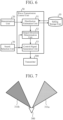
- FIG. 7 is a diagram illustrating a first concept of a state where the transmitter 300 controlled by the wave transmission control device 2 transmits waves.
- FIG. 8 is a diagram illustrating a second concept of a state where the transmitter 300 controlled by the wave transmission control device 2 transmits waves.
- the output-direction determination unit 52 in the wave-transmission control unit 50 determines an output direction as follows, for example.
- the output-direction determination unit 52 determines that the sound to be output is the preference sound on the basis of, for example, the sound type information received from the sound selection unit 30. Then, as illustrated in FIG. 7 , the output-direction determination unit 52 determines the output direction of the preference sound 311a as a direction of the region 13a, and determines the output direction of the preference sound 311b as a direction of the region 13b.
- the output-direction determination unit 52 determines that the sound to be output is the repellent sound on the basis of, for example, the sound type information received from the sound selection unit 30. Then, as illustrated in FIG. 8 , the output-direction determination unit 52 determines the output direction of the repellent sound 312a as the direction of the region 13b, and determines the output direction of the repellent sound 312b as the direction of the region 13a.
- control-signal generation unit 53 uses the output direction information received from the output-direction determination unit 52 and the sound information received from the sound selection unit 30, the control-signal generation unit 53 generates a control signal for causing the transmitter 300 to output a sound based on the sound information acquired by the sound selection unit 30 in the output direction determined by the output-direction determination unit 52.
- the control-signal generation unit 53 outputs the generated control signal.
- FIGS. 9A and 9B are diagrams illustrating a hardware configuration of the wave transmission control device 2 according to the first embodiment.
- the functions of the determination unit 20, the sound selection unit 30, and the wave-transmission control unit 50 are implemented by a processing circuit 1001. That is, the wave transmission control device 2 includes the processing circuit 1001 for executing wave transmission control to select and acquire the sound information 203 corresponding to a characteristic of the underwater organism, causing the transmitter 300 to output a sound into water using the acquired sound information 203, and forming a sound field in water.
- the processing circuit 1001 may be dedicated hardware as illustrated in FIG. 9A , or may be a central processing unit (CPU) 1005 that executes a program stored in a memory 1006 as illustrated in FIG. 9B .
- CPU central processing unit
- the processing circuit 1001 corresponds to, for example, a single circuit, a composite circuit, a programmed processor, a parallel programmed processor, an application specific integrated circuit (ASIC), a field-programmable gate array (FPGA), or a combination thereof.
- ASIC application specific integrated circuit
- FPGA field-programmable gate array
- the functions of the determination unit 20, the sound selection unit 30, and the wave-transmission control unit 50 are implemented by software, firmware, or a combination of software and firmware. That is, the functions of the determination unit 20, the sound selection unit 30, and the wave-transmission control unit 50 are implemented by a processing circuit such as the CPU 1005 that executes a program stored in a hard disk drive (HDD) 1002, a memory 1006, or the like, or a system large-scale integration (LSI). It can also be said that the program stored in the HDD 1002, the memory 1006, or the like causes a computer to execute procedures and methods of processing performed by the determination unit 20, the sound selection unit 30, and the wave-transmission control unit 50.
- HDD hard disk drive
- LSI system large-scale integration
- the memory 1006 corresponds to, for example, a nonvolatile or volatile semiconductor memory such as a random access memory (RAM), a read only memory (ROM), a flash memory, an erasable programmable read only memory (EPROM), or an electrically erasable programmable read only memory (EEPROM), a magnetic disk, a flexible disk, an optical disk, a compact disk, a mini disk, a digital versatile disc (DVD), or the like.
- RAM random access memory
- ROM read only memory
- EPROM erasable programmable read only memory
- EEPROM electrically erasable programmable read only memory
- the functions of the determination unit 20, the sound selection unit 30, and the wave-transmission control unit 50 may be implemented by dedicated hardware, whereas some thereof may be implemented by software or firmware.
- the function of the sound selection unit 30 can be implemented by the processing circuit 1001 as dedicated hardware, and the functions of the determination unit 20, the sound selection unit 30, and the wave-transmission control unit 50 can be implemented by the CPU 1005 reading and executing a program stored in the memory 1006.
- the wave transmission control device 2 includes an input interface device 1003 and an output interface device 1004 that communicate with the sensor unit 100, the sound information database 200, the transmitter 300, or the like.
- FIG. 10 is a flowchart illustrating processing of the wave transmission control device 2.
- FIG. 11 is a flowchart illustrating processing of the determination unit 20.
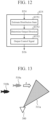
- FIG. 12 is a flowchart illustrating processing of the wave-transmission control unit 50.
- the wave transmission control device 2 starts processing (start).
- the determination unit 20 determines characteristics of an underwater organism and a distribution state of the underwater organism in water (step ST2 in FIG. 10 ).
- step ST2 the characteristic determination unit 21 in the determination unit 20 determines the characteristic of the underwater organism using the detection information, and outputs determined characteristic information indicating the determined characteristic (step ST21 in FIG. 11 ).
- the distribution determination unit 22 in the determination unit 20 determines the distribution state of the underwater organism using the detection information, and outputs determined distribution information indicating the determined distribution state (step ST22 in FIG. 11 ).
- the guidance determination unit 23 in the determination unit 20 refers to the setting storage unit 10 and determines whether or not to execute wave transmission control for guiding the underwater organism (step ST3 in FIG. 10 ). If it is determined that the wave transmission control is not executed (step ST3 "No" in FIG. 10 ), the processing returns to step ST1.
- the guidance determination unit 23 determines that the wave transmission control is executed (step ST3 "Yes" in FIG. 10 ), the guidance determination unit outputs the determined characteristic information and the determined distribution information.
- the sound selection unit 30 When acquiring the determined characteristic information, the sound selection unit 30 refers to the sound information database 200 to search for characteristic information matching the determined characteristic information, and selects and acquires sound information associated with the searched characteristic information (step ST4 in FIG. 10 ). The sound selection unit 30 outputs the acquired sound information.
- the wave-transmission control unit 50 determines a sound output direction so as to obtain a distribution state for each characteristic set in advance, and controls the transmitter 300 to output a sound based on the sound information acquired by the sound selection unit 30 in the determined output direction (step ST5 in FIG. 10 ).
- step ST5 the distribution estimation unit 51 in the wave-transmission control unit 50 compares the determined distribution information determined by the determination unit 20 with the set distribution information for each characteristic set in advance, and estimates a distribution state where the distribution state determined by the determination unit 20 becomes closer to the distribution state for each characteristic set in advance (step ST51 in FIG. 12 ).
- the output-direction determination unit 52 in the wave-transmission control unit 50 determines the sound output direction in such a manner that the distribution state estimated by the distribution estimation unit 51 is obtained (step ST52 in FIG. 12 ). Note that, in a case where both the preference sound and the repellent sound are included in the sound information database 200, in step ST52, the output-direction determination unit 52 adjusts the sound output direction based on the type of the sound information acquired by the sound selection unit 30 and then determines the sound output direction.
- the output-direction determination unit 52 outputs output direction information indicating the determined output direction.
- control-signal generation unit 53 uses the output direction information received from the output-direction determination unit 52 and the sound information received from the sound selection unit 30, the control-signal generation unit 53 generates a control signal for causing the transmitter 300 to output a sound based on the sound information acquired by the sound selection unit 30 in the output direction determined by the output-direction determination unit 52.
- the control-signal generation unit 53 outputs the generated control signal (step ST53 in FIG. 12 ).
- a control unit (not illustrated) in the wave transmission control device 2 determines whether to end the wave transmission control. Specifically, for example, the control unit uses the determined distribution information, the set distribution information 13, and the estimated distribution information to determine whether or not the current distribution state matches the distribution state indicated by the set distribution information 13.
- the control unit determines whether or not to end the wave transmission control on the basis of the determination result, and ends the processing (end in FIG. 10 ) when determining that the distribution states match and the wave transmission control is to be ended (step ST6 "Yes” in FIG. 10 ). If the control unit determines that the distribution states do not match and the wave transmission control is not ended (step ST6 "No” in FIG. 10 ), the control unit issues a command to repeat from the processing of step ST1.
- control unit may determine that the wave transmission control is ended in a case where the difference between the current distribution state and the distribution state indicated by the set distribution information 13 is equal to or less than a threshold.
- the current distribution state may be estimated using the estimated distribution information, or the determined distribution information may be obtained from newly acquired detection information.
- FIG. 13 is a first concept diagram illustrating a state where underwater organisms are guided by the transmitter 300 controlled by the wave transmission control device 2 transmitting waves.
- the setting storage unit 10 stores the set distribution information 13 indicating a distribution state where the fish 510a gather in the region 13a illustrated in FIG. 3 on the right front of the transmitter 300.
- the transmitter By the transmitter outputting the preference sound 311a to the right front region of the transmitter 300 on the basis of the control signal received from the wave-transmission control unit 50, a sound field where the fish 510a are guided is formed in the right front region of the transmitter 300.
- the fish 510a Since the sound field of the preference sound 311a for the fish 510a is formed in the region 13a, the fish 510a are guided and moved toward the sound field of the preference sound 311a as indicated by an arrow A.
- the preference sound 311a is different from the audible sound of the fish 510b or from the preference sound of the fish 510b. Therefore, the fish 510b do not move.
- FIG. 14 is a second concept diagram illustrating the state where underwater organisms are guided by the transmitter 300 controlled by the wave transmission control device 2 transmitting waves.
- the setting storage unit 10 stores the set distribution information 13 indicating a distribution state where the fish 510a gather in the region 13b illustrated in FIG. 3 on the left front of the transmitter 300.
- the transmitter 300 By the transmitter 300 outputting the repellent sound 312a to the right front region of the transmitter 300 on the basis of the control signal received from the wave-transmission control unit 50, a sound field to be avoided by the fish 510a is formed in the right front region of the transmitter 300.
- the fish 510a move as indicated by an arrow B while avoiding the sound field of the repellent sound 312a.
- the repellent sound 312a is different from the audible sound of the fish 510b or from the repellent sound 312b of the fish 510b. Therefore, the fish 510b do not move.
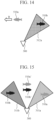
- FIG. 15 is a third concept diagram illustrating the state where underwater organisms are guided by the transmitter 300 controlled by the wave transmission control device 2 transmitting waves.
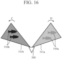
- FIG. 16 is a fourth concept diagram illustrating the state where underwater organisms are guided by the transmitter 300 controlled by the wave transmission control device 2 transmitting waves.
- the setting storage unit 10 stores the set distribution information 13 indicating a distribution state where the fish 510a gather in the region 13a illustrated in FIG. 3 on the right front of the transmitter 300, and stores the set distribution information 13 indicating a distribution state where the fish 510b gather in the region 13b illustrated in FIG. 3 .
- the transmitter By the transmitter outputting the preference sound 311a to the right front region of the transmitter on the basis of the control signal received from the wave-transmission control unit 50, a sound field where the fish 510a are guided is formed in the right front region of the transmitter 300.
- a sound field where the fish 510b are guided is formed in the left front region of the transmitter 300.
- the fish 510a move to the right front region of the transmitter 300, whereas the fish 510b move to the left front region of the transmitter.
- the wave transmission control device 2 moves fish in a horizontal direction with respect to the transmitter 300 based on the sound output direction, but it is not limited thereto, and the wave transmission control device may control the output intensity of the sound in the transmitter 300 on the basis of the distance to the fish and move the fish in a distance direction from the transmitter 300 to the fish. Furthermore, the wave transmission control device 2 may control both the sound output direction and the sound output intensity.
- the wave transmission control device controls a transmitter to form a sound field in water
- the wave transmission control device including a determination unit to, when detection information is input from a sensor unit to detect an organism in water, perform determination of a characteristic of the organism among a plurality of characteristics and a distribution state for said characteristic using the detection information, a sound selection unit to acquire sound information based on a characteristic determined by the determination unit by referring to a database in which the plurality of characteristics and a plural pieces of sound information are respectively associated with each other, and a wave-transmission control unit to determine a sound output condition in such a manner that a distribution state changes from the distribution state determined by the determination unit to a set distribution state which is set for each of the plurality of characteristics received before processing starts and to cause the transmitter to output a sound based on the sound information acquired by the sound selection unit using the sound output condition.
- the wave-transmission control unit includes the distribution estimation unit to estimate an estimated distribution state where the distribution state determined by the determination unit becomes closer to the set distribution state by comparing the distribution state determined by the determination unit with the set distribution state, and the output-condition determination unit to determine a sound output condition so as to obtain the estimated distribution state estimated by the distribution estimation unit.
- the wave-transmission control unit repeats processing of determining the sound output condition and causing the transmitter to output a sound based on the sound information acquired by the sound selection unit using the sound output condition until the distribution state determined by the determination unit changes to the set distribution state.
- the characteristic of the organism includes a type of the organism.
- the characteristic of the organism includes a size of the organism.
- the characteristic of the organism includes a type of the organism and a size of the organism.
- the wave-transmission control unit causes the transmitter to output a preference sound preferred by the organism.
- the wave-transmission control unit causes the transmitter to output a repellent sound of an organism.
- the wave-transmission control unit causes the transmitter to output a preference sound preferred by the organism and a repellent sound of the organism as the different sounds.
- the underwater organism guidance device includes a transmitter to form a sound field in water, the determination unit to, when detection information is input from a sensor unit to detect an organism in water, perform determination of a characteristic of the organism among a plurality of characteristics and a distribution state for said characteristic using the detection information, the sound selection unit to acquire sound information based on a characteristic determined by the determination unit using a database in which a plural pieces of information of the plurality of characteristics of organisms and a plural pieces of sound information are respectively associated with each other, and the wave-transmission control unit to determine a sound output condition in such a manner that a distribution state changes from the distribution state determined by the determination unit to a set distribution state which is set for each of the plurality of characteristics received before processing starts and to cause the transmitter to output a sound based on sound information acquired by the sound selection unit using the sound output condition.
- the wave-transmission control unit includes the distribution estimation unit to estimate an estimated distribution state where the distribution state determined by the determination unit becomes closer to the set distribution state by comparing the distribution state determined by the determination unit with the set distribution state, and an output-condition determination unit to determine a sound output condition so as to obtain the estimated distribution state estimated by the distribution estimation unit
- the wave-transmission control unit repeats processing of determining the sound output condition and causing the transmitter to output a sound based on sound information acquired by the sound selection unit using the output condition until the distribution state determined by the determination unit changes to the set distribution state.
- the transmitter includes an underwater speaker.
- the transmitter includes a superdirectional speaker.
- the transmitter includes a speaker array.
- the transmitter includes a drive unit to change a direction in which the transmitter transmits a wave in accordance with the sound output condition determined by the wave-transmission control unit.
- the wave transmission control method is a method to control a transmitter to form a sound field in water, the wave transmission control method including a determination step to, when detection information is input from a sensor unit to detect an organism in water, cause a determination unit to perform determination of a characteristic of the organism among a plurality of characteristics and a distribution state for said characteristic using the detection information, a sound acquisition step to cause a sound selection unit to acquire sound information based on the characteristic determined by the determination unit using a database in which a plural pieces of information of the plurality of characteristics of organisms and a plural pieces of sound information are respectively associated with each other, and a wave-transmission control step to cause a wave-transmission control unit to determine a sound output condition in such a manner that a distribution state changes from the distribution state determined by the determination unit to a set distribution state which is set for each of the plurality of characteristics received before processing starts and to cause the transmitter to output a sound based on sound information acquired by the sound selection unit using the output condition.
- the wave transmission control device can select a sound for each characteristic of an underwater organism, output the sound so as to satisfy an output condition for obtaining a distribution state for each characteristic, and sort and guide the underwater organism based on each characteristic, and thus is suitable for use in an underwater organism guidance device.
- 1 underwater organism guidance device
- 2 wave transmission control device
- 10 setting storage unit
- 11 identification information (set identification information), 12: characteristic information (set characteristic information), 13: distribution information (set distribution information), 13a, 13b: region
- 20 determination unit
- 30 sound selection unit
- 53 control-signal generation unit
- 200 sound information database
- 201 identification information
- 202 characteristic information
- 203 sound information
- 300 transmitter
- 311a, 3 11b preference sound
- 312a, 312b repellent sound
- 510a, 510a', 510b, 510b' underwater organism
- 1003 input interface device
- 1006 memory
- 1007 HDD
Landscapes
- Life Sciences & Earth Sciences (AREA)
- Environmental Sciences (AREA)
- Zoology (AREA)
- Birds (AREA)
- Biodiversity & Conservation Biology (AREA)
- Animal Husbandry (AREA)
- Marine Sciences & Fisheries (AREA)
- Engineering & Computer Science (AREA)
- Insects & Arthropods (AREA)
- Pest Control & Pesticides (AREA)
- Wood Science & Technology (AREA)
- Measurement Of Velocity Or Position Using Acoustic Or Ultrasonic Waves (AREA)
- Mechanical Means For Catching Fish (AREA)
- Farming Of Fish And Shellfish (AREA)
Description
- The present disclosure relates to a wave transmission control device that outputs sound waves for moving organisms in water.
- Conventionally, there is known a technique of moving organisms in water (hereinafter, referred to as "underwater organisms"). For example, Patent Literature 1 discloses a crustacean plankton catching method in which a group of crustacean plankton in the sea is moved. Specifically, when a group of crustacean plankton swimming in the sea is found by a fish detection device, sound wave generators are arranged in the sea so as to surround the group. When moving the group, the sound wave generators sequentially transmit a sound from the sound wave generator disposed below the group to the sound wave generator disposed above the group while detecting the position of the group, and move the group toward the sea surface. As a result, the crustacean plankton sequentially moves from the lower side to the upper side in the sea within the range surrounded by the sound wave generators.
Patent Literature 2 discloses acoustic devices, attached to fishing nets, which emit a deterrent signal to a particular marine animal on actuation by the approach of the animal. Patent Literature 3 discloses a programmable, customizable system, method, and apparatus for attracting and stimulating aquatic animals. Patent Literature 4 discloses a device for modifying the behavior of fish, causing them to swim along a desired path, wherein the device projects sequences of sound into the water, resulting in sound wave patterns which direct the fish along the desired path. Patent Literature 5 discloses a device having a sound acquisition unit for acquiring sound to be outputted by a transmitter and a sound-field formation control unit for determining a range in which a sound-field is formed in water and for causing the transmitter to output the sound acquired by the sound acquisition unit to the determined range. -
- Patent Literature 1:
JP 52-016385 A - Patent Literature 2:
US 6 170 436 B1 - Patent Literature 3:
US 2006/268664 A1 - Patent Literature 4:
US 4 932 007 A - Patent Literature 5:
WO 2019/229981 A1 - However, in the conventional technique, there is a problem that, in a case where a plurality of underwater organisms with different characteristics are mixed in water, in addition to underwater organisms to be guided, other underwater organisms are unintendedly guided.
- In a case where the crustacean plankton catching method described in Patent Literature 1 is applied to the case where a plurality of underwater organisms with different characteristics are mixed, it is not possible to sort and guide the underwater organisms, and the problem still cannot be solved.
- The present disclosure has been made to solve the above problems, and an object of the present disclosure is to provide a wave transmission control device that sorts and guides underwater organisms based on each characteristic even in a case where a plurality of organisms with different characteristics are mixed in water.
- The invention is set out in the appended set of claims. A wave transmission control device according to the present disclosure performs control of a transmitter to form a sound field in water, the wave transmission control device including: a determination unit to, when detection information is input from a sensor to detect an organism in water, perform determination of a characteristic of the organism among a plurality of characteristics and a distribution state for said characteristic using the detection information; a sound selection unit to acquire sound information based on the characteristic determined by the determination unit by referring to a database in which the plurality of characteristics and a plural pieces of sound information are respectively associated with each other; and a wave-transmission control unit to determine a sound output condition in such a manner that a distribution state changes from the distribution state determined by the determination unit to a set distribution state which is set for each of the plurality of characteristics received before processing starts and to cause the transmitter to output a sound based on the sound information acquired by the sound selection unit using the sound output condition
- According to the present disclosure, with the above configuration, it has the effect of providing a wave transmission control device that sorts and guides underwater organisms based on each characteristic.
-
-
FIG. 1 is a diagram illustrating an example of a configuration of an underwater organism guidance device and a wave transmission control device according to a first embodiment. -
FIG. 2 is a diagram illustrating an example of information stored in a setting storage unit. -
FIG. 3 is a concept diagram illustrating an example of a distribution state set in the wave transmission control device. -
FIG. 4 is a diagram illustrating a configuration of a determination unit in the wave transmission control device. -
FIG. 5 is a diagram illustrating an example of information stored in a database used in the underwater organism guidance device. -
FIG. 6 is a diagram illustrating a configuration of a wave-transmission control unit in the wave transmission control device. -
FIG. 7 is a diagram illustrating a first concept of a state where a transmitter controlled by the wave transmission control device transmits waves. -
FIG. 8 is a diagram illustrating a second concept of the state where the transmitter controlled by the wave transmission control device transmits waves. -
FIGS. 9A and 9B are diagrams illustrating a hardware configuration of the underwater organism guidance device and the wave transmission control device according to the first embodiment. -
FIG. 10 is a flowchart illustrating processing performed by the wave transmission control device. -
FIG. 11 is a flowchart illustrating processing performed by the determination unit. -
FIG. 12 is a flowchart illustrating processing performed by the wave-transmission control unit. -
FIG. 13 is a first concept diagram illustrating a state where underwater organisms are guided by the transmitter controlled by the wave transmission control device transmitting waves. -
FIG. 14 is a second concept diagram illustrating the state where underwater organisms are guided by the transmitter controlled by the wave transmission control device transmitting waves. -
FIG. 15 is a third concept diagram illustrating the state where underwater organisms are guided by the transmitter controlled by the wave transmission control device transmitting waves. -
FIG. 16 is a fourth concept diagram illustrating the state where underwater organisms are guided by the transmitter controlled by the wave transmission control device transmitting waves. - Hereinafter, an underwater organism guidance device and a wave transmission control device according to the present disclosure will be described with reference to the accompanying drawings.
- In the present disclosure, organisms in water are referred to as "underwater organisms". The underwater organisms include all organisms in water. In addition, underwater includes a benthic region.
- Furthermore, sound or sound waves are used in the present disclosure. The sound or sound waves include frequencies below the human audible range and frequencies above the human audible range (ultrasound waves).
-
FIG. 1 is a diagram illustrating an example of a configuration of an underwater organism guidance device and a wave transmission control device according to the present disclosure. - An underwater organism guidance device 1 guides underwater organisms in such a manner that a desired distribution is obtained for each characteristic of underwater organisms. In a case where a plurality of organisms with different characteristics are mixed in water, the underwater organism guidance device 1 guides at least one type of fish as a guidance target using a sound and sorts the fish from other types of fish.
- For example, the underwater organism guidance device 1 is assumed to be used for guiding one type of fish in the direction of a fishing net when fishing is performed in the sea.
- In addition, the underwater organism guidance device 1 is assumed to be used, for example, for guiding adult fish in the direction of a fishing net, keeping juvenile fish away from the fishing net, and preventing overfishing of the juvenile fish.
- Furthermore, the underwater organism guidance device 1 is assumed to be used, for example, for feeding small fish with a body length less than a threshold after keeping large fish with a body length larger than or equal to the threshold away from a feeding position when feeding the fish in an aquaculture farm.
- Moreover, the underwater organism guidance device 1 is assumed to be used, for example, for separately guiding specific types of fish in a water tank of an aquarium.
- The underwater organism guidance device 1 illustrated in
FIG. 1 includes a wavetransmission control device 2, asensor unit 100, asound information database 200, and atransmitter 300. - The wave
transmission control device 2, thesensor unit 100, thesound information database 200, and thetransmitter 300 are communicably connected to each other. - The wave
transmission control device 2 selects sound information with reference to thesound information database 200 by using detection information from thesensor unit 100 and distribution information indicating a distribution state being a guidance target, determines a sound output condition, and controls thetransmitter 300 by using the output condition to form a sound field in water. Details of the wavetransmission control device 2 and thesound information database 200 will be described later. - The
sensor unit 100 detects underwater organisms and outputs detection information. Thesensor unit 100 detects underwater organisms using, for example, a sound wave, a radio wave, or light, and outputs detection information. Alternatively, thesensor unit 100 detects underwater organisms using, for example, an image captured by a camera, and outputs detection information. Alternatively, thesensor unit 100 may detect underwater organisms using two or more of a sound wave, a radio wave, light, and an image captured by a camera, and output the detection information. - The
transmitter 300 is provided in water. Thetransmitter 300 is attached to the hull of a ship, for example. Alternatively, thetransmitter 300 is attached to a structure provided in, for example, the ocean, a river, or a water tank. The structure includes a structure floating on the water in addition to a structure fixed to a shore or a benthic region. - The
transmitter 300 outputs directional sound waves into water to form a sound field in the water. Thetransmitter 300 is, for example, a speaker, and is specifically an underwater speaker, a superdirectional speaker, an ultrasonic speaker, or an ultrasonic sensor. In addition, thetransmitter 300 may be a speaker array including a plurality of any of the above and arranged in an array. That is, the transmitter includes, for example, one or a plurality of speakers. - The
transmitter 300 may output directional sound waves in a plurality of different directions in water. - Further, the
transmitter 300 may include a drive unit (not illustrated) that changes a direction in which thetransmitter 300 transmits waves in accordance with an output direction included in the output condition determined by a wave-transmission control unit 50. - In this case, when receiving a control signal from the wave-
transmission control unit 50, the drive unit mechanically changes the direction of thetransmitter 300 in accordance with the output direction indicated by the control signal. - As a result, in the water where the
transmitter 300 can transmit waves, the wave-transmission control unit 50 can further cause thetransmitter 300 to form a sound field in any direction in water and in any range in water. - In a case where the plurality of
transmitters 300 are provided and the plurality oftransmitters 300 are installed at different positions, the wave-transmission control unit 50 controls the amplitude and phase of a sound output from each of thetransmitters 300. As a result, in the water where thetransmitter 300 can transmit waves, it is possible to cause thetransmitter 300 to form a sound field in any direction in water and in any range in water. - Details of the wave
transmission control device 2 and thesound information database 200 will be described. - The wave
transmission control device 2 illustrated inFIG. 1 includes a settingstorage unit 10, adetermination unit 20, asound selection unit 30, and the wave-transmission control unit 50. - In addition, the wave
transmission control device 2 includes a control unit (not illustrated). The control unit issues a command to start, continue, and end the entire processing of the wavetransmission control device 2 on the basis of information acquired from the inside and the outside of the wavetransmission control device 2. For example, the control unit determines whether or not to end wave transmission control each time the wavetransmission control device 2 executes control on thetransmitter 300. When determining to end the wave transmission control, the control unit ends the processing performed by the wavetransmission control device 2. When determining not to end the wave transmission control, the control unit issues a command to repeat the processing related to the wave transmission control from the beginning. When repeating the processing related to the wave transmission control, the control unit may issue a command to omit the processing performed by thesound selection unit 30 in the second and subsequent processing. - The setting
storage unit 10 stores a distribution state for each characteristic set in advance. Specifically, the settingstorage unit 10 stores in advance information indicating characteristics of an underwater organism and information indicating a distribution state of the underwater organism in water before the wavetransmission control device 2 starts wave transmission control processing on thetransmitter 300. - The information indicating the characteristics of the underwater organism and the information indicating the distribution state of the underwater organism in water are, for example, information set by a user before the wave
transmission control device 2 starts the control processing. In other words, the information stored in the settingstorage unit 10 indicates the distribution state in water of each underwater organism (guidance target) that the user desires to guide. It is only required that this information is received and stored at the latest until immediately before the wavetransmission control device 2 starts control. - Furthermore, information set in the setting
storage unit 10 will be described. -
FIG. 2 is a diagram illustrating an example of information stored in the settingstorage unit 10. - The setting
storage unit 10stores identification information 11,characteristic information 12, anddistribution information 13 in association with one another. The settingstorage unit 10 may store a plurality of sets of theidentification information 11, thecharacteristic information 12, and thedistribution information 13. - The
identification information 11 in the settingstorage unit 10 is information for identifying a combination of thecharacteristic information 12 and thedistribution information 13 in a case where a plurality of sets of thecharacteristic information 12 and thedistribution information 13 are stored in the settingstorage unit 10. Theidentification information 11 is, for example, alphanumeric characters that do not overlap in combinations of thecharacteristic information 12 and thedistribution information 13. - The
characteristic information 12 in the settingstorage unit 10 indicates characteristics of the underwater organism set in advance. Thecharacteristic information 12 is, for example, at least one of information indicating the type of the underwater organism or information indicating the size of the underwater organism. - The
distribution information 13 indicates the distribution state of the underwater organism in water. Thedistribution information 13 indicates, for example, at least one of a direction of a region in water, a distance to the region, or a position of the region based on an installation position of thetransmitter 300. Furthermore, thedistribution information 13 may include the area of the region. - In the following description, the
identification information 11 set in the settingstorage unit 10 may be referred to as "setidentification information 11", and similarly, thecharacteristic information 12 may be referred to as "setcharacteristic information 12", and thedistribution information 13 may be referred to as "setdistribution information 13". In addition, the distribution state indicated by the setdistribution information 13 may be referred to as "set distribution state". - In the following description, a case where the direction of a region in water based on the installation position of the
transmitter 300 is used will be described as a representative, but the present disclosure is not limited to this case. - Note that, in a case where only one set of information is set in the setting
storage unit 10, theset identification information 11 is not essential. -
FIG. 3 is a concept diagram illustrating an example of a distribution state set in the wavetransmission control device 2. - For example, as illustrated in
FIG. 3 , the settingstorage unit 10 stores setdistribution information 13 indicating a distribution state wherefish 510a are present in aregion 13a on the right front of the transmitter, and stores setdistribution information 13 indicating a distribution state wherefish 510b are present in aregion 13b on the left front of the transmitter. Here, thefish 510a and thefish 510b are different types of fish, and have different audible sounds from each other, or have different preference sounds and repellent sounds from each other. - When detection information is input from the
sensor unit 100 that detects an underwater organism, thedetermination unit 20 determines the characteristics of the underwater organism and the distribution state of the underwater organism for said characteristic using the detection information. Thedetermination unit 20 outputs the characteristic information indicating the characteristic of the underwater organism and the distribution information indicating the distribution state of the organism for each characteristic. -
FIG. 4 is a diagram illustrating a configuration of thedetermination unit 20 in the wavetransmission control device 2. -
FIG. 4 illustrates the configuration of thedetermination unit 20 and a relationship with peripheral components. - The
determination unit 20 illustrated inFIG. 4 includes acharacteristic determination unit 21, adistribution determination unit 22, and aguidance determination unit 23. - The
characteristic determination unit 21 determines the characteristic of the underwater organism detected by thesensor unit 100 using the detection information received from thesensor unit 100. The characteristic of the underwater organism is, for example, the type, size, or degree of growth of the underwater organism. The technique of determining the type, size, or degree of growth of the underwater organism using the detection information from thesensor unit 100 can be implemented using a known technique. Therefore, detailed description is omitted here. - The
characteristic determination unit 21 outputs characteristic information indicating the determined characteristic. Hereinafter, the characteristic information output by thecharacteristic determination unit 21 may be referred to as "determined characteristic information". - The
distribution determination unit 22 determines the distribution state of the underwater organism detected by thesensor unit 100 using the detection information received from thesensor unit 100. Thedistribution determination unit 22 outputs distribution information indicating the determined distribution state. The distribution information determined by thedistribution determination unit 22 indicates a region where the underwater organism is currently present. Specifically, the distribution information determined by thedistribution determination unit 22 indicates any one of the direction of the region in water, the distance to the region, and the position of the region based on the installation position of thetransmitter 300. In addition thereto, information indicating the area of the region may be included. Hereinafter, the distribution information output by thedistribution determination unit 22 may be referred to as "determined distribution information". - The
guidance determination unit 23 determines whether to execute wave transmission control for guiding the underwater organism. - Specifically, the
guidance determination unit 23 refers to the settingstorage unit 10 and determines whether or not the determined characteristic information received from thecharacteristic determination unit 21 matches the setcharacteristic information 12. As a result, when determining that they match, theguidance determination unit 23 can determine that the underwater organism detected by thesensor unit 100 is the underwater organism to be guided. - In addition, the
guidance determination unit 23 refers to the settingstorage unit 10 and determines whether or not the determined distribution information received from thedistribution determination unit 22 matches the setdistribution information 13. As a result, when determining that they match, theguidance determination unit 23 can determine that the wave transmission control is executed to guide the underwater organism. - When determining that the wave transmission control is executed, the
guidance determination unit 23 outputs the determined characteristic information and the determined distribution information. - Note that when comparing the determined distribution information with the set
distribution information 13 and determining that the difference is equal to or less than a threshold, theguidance determination unit 23 may determine that the wave transmission control is not executed, and when determining that the difference exceeds the threshold, the guidance determination unit may determine that the wave transmission control is executed. - The
sound selection unit 30 refers to thesound information database 200 in which the characteristic of the underwater organism and the sound information are associated, and acquires sound information based on the characteristic determined by thedetermination unit 20. Specifically, thesound selection unit 30 refers to thesound information database 200 to search for characteristic information matching the determined characteristic information, and selects and acquires sound information associated with the searched characteristic information. Thesound selection unit 30 outputs the acquired sound information. - Here, the
sound information database 200 will be described. -
FIG. 5 is a diagram illustrating an example of information stored in thesound information database 200 used in the underwater organism guidance device 1. - In
FIG. 5 , thesound information database 200stores identification information 201,characteristic information 202, andsound information 203 in association with one another. - The
identification information 201 in thesound information database 200 is information for identifying a combination of thecharacteristic information 202 and thesound information 203. Theidentification information 201 includes, for example, alphabetical character strings or the like that are different for each pieces of set information. - The
characteristic information 202 in thesound information database 200 indicates characteristics of the underwater organism. Thecharacteristic information 202 is, for example, type information indicating the type of the underwater organism or size information indicating the size of the underwater organism. Specifically, the type information is fish name information such as "sardine" or "sea bream", and the size information is information indicating a body length such as "10 cm", or "adult fish" or "juvenile fish" based on the body length. In addition, thecharacteristic information 202 may be a value indicating the degree of growth of the underwater organism. Furthermore, thecharacteristic information 202 may be information indicating the combination of the type information and the size information. - The
sound information 203 in thesound information database 200 indicates an audible sound based on the auditory characteristic of each underwater organism. Thesound information 203 indicates, for example, a frequency band and a wave transmission pattern in which the intensity of a sound changes with time. - Here, the auditory sense of underwater organisms will be described by taking fish as an example. The fish have auditory characteristics, and for example, the audible range varies depending on the type and size of the fish. That is, there is an audible sound corresponding to the type and size of fish.
- In the audible range of fish, there are a preference sound and a repellent sound corresponding to the breeding environment of fish.
- For example, in a natural environment such as the sea, a predation sound generated at the time of preying on bait is a preference sound, whereas a barking sound generated against an action of a natural enemy is a repellent sound.
- In addition, for example, in a breeding environment such as an aquaculture farm, a feeding sound generated when a feeder operates is a preference sound, whereas a sound that fish has intentionally trained to avoid is a repellent sound. As a method of intentionally training fish to avoid, there is a method of training the fish by repeating a series of processes of vibrating water immediately after generating a certain sound and causing the fish to move away from the current position.
- Information indicating these preference sound and repellent sound is set as the
sound information 203 in thesound information database 200. - In a case where the
sound information 203 in thesound information database 200 includes both the preference sound and the repellent sound, sound type information capable of identifying that the sound is the preference sound or the repellent sound is further given to each combination of thecharacteristic information 202 and thesound information 203. When the wave-transmission control unit 50 determines a sound output condition, the sound type information is used, for example, in processing of determining a direction in which the underwater organism is to be guided as the output direction in a case where the sound type information indicates the preference sound, and in processing of determining a direction opposite to the direction in which the underwater organism is to be guided as the output direction in a case where the sound type information indicates the repellent sound. - In addition, in a case where the
sound information 203 includes both the preference sound and the repellent sound, the preference sound and the repellent sound can be used for processing in which both sounds are used in combination. For example, in a case where it is desired to catch only a specific fish species A, the preference sound of the fish species A to be caught is selected, the preference sound of the fish species A is output to a desired position, and the fish species A is guided to a catch position. On the other hand, for the underwater organisms other than the fish species A, the repellent sound of the underwater organisms other than the fish species A is output to the position where the preference sound of the fish species A is output to move the underwater organisms other than the fish species A away from the catch position. - The
sound information 203 in thesound information database 200 may be only the preference sound or only the repellent sound. - Note that, in
FIG. 1 , thesound information database 200 is configured to be included in the underwater organism guidance device 1 and is provided outside the wavetransmission control device 2, but is not limited thereto. Thesound information database 200 may be, for example, a database outside the underwater organism guidance device 1, and thesound information database 200 may be provided inside the wavetransmission control device 2, for example. - Furthermore, although the
sound information database 200 is illustrated in the present disclosure, for example, thesound information database 200 may be provided in a cloud or the like that can be referred to by the underwater organism guidance device 1, or may be provided in a portable storage medium such as an SD card. - That is, the sound information database is only required to be communicably connected to the wave
transmission control device 2. - The wave-
transmission control unit 50 illustrated inFIG. 1 determines a sound output condition so as to guide an underwater organism to be guided to a region to be guided, and executes control to cause thetransmitter 300 to output a sound using the output condition. - Specifically, the wave-
transmission control unit 50 determines a sound output condition so as to obtain a distribution state (a distribution state indicated by set distribution information) for each characteristic set in advance in the settingstorage unit 10, and causes thetransmitter 300 to output a sound based on the sound information acquired by thesound selection unit 30 in such a manner that the determined output condition is satisfied. - Furthermore, the wave-
transmission control unit 50 repeats processing of determining a sound output condition and causing thetransmitter 300 to output a sound based on the sound information acquired by thesound selection unit 30 in such a manner that the determined output condition is satisfied until the distribution state changes from the distribution state determined by thedetermination unit 20 to the distribution state indicated by the set distribution information. -
FIG. 6 is a diagram illustrating a configuration of the wave-transmission control unit 50 in the wavetransmission control device 2. -
FIG. 6 illustrates the configuration of the wave-transmission control unit 50 and a relationship with peripheral components. - The wave-
transmission control unit 50 illustrated inFIG. 6 includes adistribution estimation unit 51, an output-direction determination unit 52, and a control-signal generation unit 53. In the present disclosure, the output-direction determination unit 52 is an example of an output-condition determination unit that determines a sound output condition. - The
distribution estimation unit 51 compares the distribution state determined by thedetermination unit 20 with the distribution state indicated by the set distribution information, and estimates a distribution state where the distribution state determined by thedetermination unit 20 becomes closer to the distribution state indicated by the set distribution information. - Specifically, when receiving the determined characteristic information and the determined distribution information from the
determination unit 20, thedistribution estimation unit 51 compares the determined distribution information with the set distribution information for each characteristic stored in the settingstorage unit 10. Thedistribution estimation unit 51 estimates a distribution state where the distribution state indicated by the determined distribution information becomes closer to the distribution state indicated by the set distribution information. - The method of estimating the distribution state where the current distribution state is brought close to the distribution state for each characteristic set in advance can be implemented by a known technique such as artificial intelligence (AI). In addition, for example, it can be implemented by changing the distance between the coordinates of two different distributions so as to gradually decrease. Therefore, a more detailed description will be omitted.
- The
distribution estimation unit 51 outputs distribution information indicating the estimated distribution state. Specifically, the distribution information output from thedistribution estimation unit 51 indicates any one of the direction of the region in water, the distance to the region, and the position of the region based on the installation position of thetransmitter 300. In addition thereto, information indicating the area of the region may be included. Hereinafter, the distribution information output by thedistribution estimation unit 51 may be referred to as "estimated distribution information". - The output-
direction determination unit 52 determines a sound output direction in such a manner that the distribution state estimated by thedistribution estimation unit 51 is obtained. - Specifically, for example, in a case where the preference sound is output, the output-
direction determination unit 52 determines the direction indicated by the estimated distribution information as the output direction. Furthermore, for example, in a case where the repellent sound is output, the output-direction determination unit 52 determines the direction opposite to the direction indicated by the estimated distribution information as the output direction with respect to the region indicated by the determined distribution information. - The output-
direction determination unit 52 outputs output direction information indicating the determined output direction. - Note that, in a case where the distribution information indicates a direction, the output-
direction determination unit 52 determines only the sound output direction, but the output-direction determination unit 52 can be changed to an output-condition determination unit corresponding to the distribution state indicated by the distribution information. - For example, in a case where the distribution information indicates a distance, the output-
direction determination unit 52 may be changed to an output-intensity determination unit, and the output-intensity determination unit determines the intensity of the sound to be output. - Furthermore, for example, in a case where the distribution information indicates a position, the output-
direction determination unit 52 may be changed to an output-direction intensity determination unit, and the output-direction intensity determination unit determines the sound output direction and the intensity of the sound to be output. - That is, the output-condition determination unit may be any of the output-
direction determination unit 52, the output-intensity determination unit, and the output-direction intensity determination unit. - Furthermore, for example, in a case where the area is included in the distribution information, each of the output-
direction determination unit 52, the output-intensity determination unit, and the output-direction intensity determination unit may determine the degree of directivity at the time of outputting a sound. -
FIG. 7 is a diagram illustrating a first concept of a state where thetransmitter 300 controlled by the wavetransmission control device 2 transmits waves. -
FIG. 8 is a diagram illustrating a second concept of a state where thetransmitter 300 controlled by the wavetransmission control device 2 transmits waves. - The output-
direction determination unit 52 in the wave-transmission control unit 50 determines an output direction as follows, for example. - In a case where the sound information acquired by the
sound selection unit 30 is a preference sound 311a of thefish 510a and apreference sound 311b of thefish 510b, the output-direction determination unit 52 determines that the sound to be output is the preference sound on the basis of, for example, the sound type information received from thesound selection unit 30. Then, as illustrated inFIG. 7 , the output-direction determination unit 52 determines the output direction of thepreference sound 311a as a direction of theregion 13a, and determines the output direction of thepreference sound 311b as a direction of theregion 13b. - On the other hand, in a case where the sound information acquired by the
sound selection unit 30 is arepellent sound 312a of thefish 510a and arepellent sound 312b of thefish 510b, the output-direction determination unit 52 determines that the sound to be output is the repellent sound on the basis of, for example, the sound type information received from thesound selection unit 30. Then, as illustrated inFIG. 8 , the output-direction determination unit 52 determines the output direction of therepellent sound 312a as the direction of theregion 13b, and determines the output direction of therepellent sound 312b as the direction of theregion 13a. - Using the output direction information received from the output-
direction determination unit 52 and the sound information received from thesound selection unit 30, the control-signal generation unit 53 generates a control signal for causing thetransmitter 300 to output a sound based on the sound information acquired by thesound selection unit 30 in the output direction determined by the output-direction determination unit 52. The control-signal generation unit 53 outputs the generated control signal. -
FIGS. 9A and 9B are diagrams illustrating a hardware configuration of the wavetransmission control device 2 according to the first embodiment. - In the first embodiment, the functions of the
determination unit 20, thesound selection unit 30, and the wave-transmission control unit 50 are implemented by aprocessing circuit 1001. That is, the wavetransmission control device 2 includes theprocessing circuit 1001 for executing wave transmission control to select and acquire thesound information 203 corresponding to a characteristic of the underwater organism, causing thetransmitter 300 to output a sound into water using the acquiredsound information 203, and forming a sound field in water. - The
processing circuit 1001 may be dedicated hardware as illustrated inFIG. 9A , or may be a central processing unit (CPU) 1005 that executes a program stored in amemory 1006 as illustrated inFIG. 9B . - In a case where the
processing circuit 1001 is dedicated hardware, theprocessing circuit 1001 corresponds to, for example, a single circuit, a composite circuit, a programmed processor, a parallel programmed processor, an application specific integrated circuit (ASIC), a field-programmable gate array (FPGA), or a combination thereof. - In a case where the
processing circuit 1001 is theCPU 1005, the functions of thedetermination unit 20, thesound selection unit 30, and the wave-transmission control unit 50 are implemented by software, firmware, or a combination of software and firmware. That is, the functions of thedetermination unit 20, thesound selection unit 30, and the wave-transmission control unit 50 are implemented by a processing circuit such as theCPU 1005 that executes a program stored in a hard disk drive (HDD) 1002, amemory 1006, or the like, or a system large-scale integration (LSI). It can also be said that the program stored in theHDD 1002, thememory 1006, or the like causes a computer to execute procedures and methods of processing performed by thedetermination unit 20, thesound selection unit 30, and the wave-transmission control unit 50. Here, thememory 1006 corresponds to, for example, a nonvolatile or volatile semiconductor memory such as a random access memory (RAM), a read only memory (ROM), a flash memory, an erasable programmable read only memory (EPROM), or an electrically erasable programmable read only memory (EEPROM), a magnetic disk, a flexible disk, an optical disk, a compact disk, a mini disk, a digital versatile disc (DVD), or the like. - Note that some of the functions of the
determination unit 20, thesound selection unit 30, and the wave-transmission control unit 50 may be implemented by dedicated hardware, whereas some thereof may be implemented by software or firmware. For example, the function of thesound selection unit 30 can be implemented by theprocessing circuit 1001 as dedicated hardware, and the functions of thedetermination unit 20, thesound selection unit 30, and the wave-transmission control unit 50 can be implemented by theCPU 1005 reading and executing a program stored in thememory 1006. - In addition, the wave
transmission control device 2 includes aninput interface device 1003 and anoutput interface device 1004 that communicate with thesensor unit 100, thesound information database 200, thetransmitter 300, or the like. - Next, processing of the wave
transmission control device 2 according to the first embodiment will be described. -
FIG. 10 is a flowchart illustrating processing of the wavetransmission control device 2. -
FIG. 11 is a flowchart illustrating processing of thedetermination unit 20. -
FIG. 12 is a flowchart illustrating processing of the wave-transmission control unit 50. - For example, when receiving a start command from a user and detection information from the
sensor unit 100, the wavetransmission control device 2 starts processing (start). - When acquiring the detection information (step ST1 in
FIG. 10 ), thedetermination unit 20 determines characteristics of an underwater organism and a distribution state of the underwater organism in water (step ST2 inFIG. 10 ). - Specifically, in step ST2, for example, as illustrated in
FIG. 11 , thecharacteristic determination unit 21 in thedetermination unit 20 determines the characteristic of the underwater organism using the detection information, and outputs determined characteristic information indicating the determined characteristic (step ST21 inFIG. 11 ). In addition, thedistribution determination unit 22 in thedetermination unit 20 determines the distribution state of the underwater organism using the detection information, and outputs determined distribution information indicating the determined distribution state (step ST22 inFIG. 11 ). - Using the determined characteristic information and the determined distribution information output from the
determination unit 20, theguidance determination unit 23 in thedetermination unit 20 refers to the settingstorage unit 10 and determines whether or not to execute wave transmission control for guiding the underwater organism (step ST3 inFIG. 10 ). If it is determined that the wave transmission control is not executed (step ST3 "No" inFIG. 10 ), the processing returns to step ST1. - If the
guidance determination unit 23 determines that the wave transmission control is executed (step ST3 "Yes" inFIG. 10 ), the guidance determination unit outputs the determined characteristic information and the determined distribution information. - When acquiring the determined characteristic information, the
sound selection unit 30 refers to thesound information database 200 to search for characteristic information matching the determined characteristic information, and selects and acquires sound information associated with the searched characteristic information (step ST4 inFIG. 10 ). Thesound selection unit 30 outputs the acquired sound information. - When receiving the sound information from the
sound selection unit 30, the wave-transmission control unit 50 determines a sound output direction so as to obtain a distribution state for each characteristic set in advance, and controls thetransmitter 300 to output a sound based on the sound information acquired by thesound selection unit 30 in the determined output direction (step ST5 inFIG. 10 ). - Specifically, in step ST5, for example, as illustrated in
FIG. 12 , thedistribution estimation unit 51 in the wave-transmission control unit 50 compares the determined distribution information determined by thedetermination unit 20 with the set distribution information for each characteristic set in advance, and estimates a distribution state where the distribution state determined by thedetermination unit 20 becomes closer to the distribution state for each characteristic set in advance (step ST51 inFIG. 12 ). - Next, the output-
direction determination unit 52 in the wave-transmission control unit 50 determines the sound output direction in such a manner that the distribution state estimated by thedistribution estimation unit 51 is obtained (step ST52 inFIG. 12 ). Note that, in a case where both the preference sound and the repellent sound are included in thesound information database 200, in step ST52, the output-direction determination unit 52 adjusts the sound output direction based on the type of the sound information acquired by thesound selection unit 30 and then determines the sound output direction. - The output-
direction determination unit 52 outputs output direction information indicating the determined output direction. - Next, using the output direction information received from the output-
direction determination unit 52 and the sound information received from thesound selection unit 30, the control-signal generation unit 53 generates a control signal for causing thetransmitter 300 to output a sound based on the sound information acquired by thesound selection unit 30 in the output direction determined by the output-direction determination unit 52. The control-signal generation unit 53 outputs the generated control signal (step ST53 inFIG. 12 ). - A control unit (not illustrated) in the wave
transmission control device 2 determines whether to end the wave transmission control. Specifically, for example, the control unit uses the determined distribution information, the setdistribution information 13, and the estimated distribution information to determine whether or not the current distribution state matches the distribution state indicated by the setdistribution information 13. - The control unit determines whether or not to end the wave transmission control on the basis of the determination result, and ends the processing (end in
FIG. 10 ) when determining that the distribution states match and the wave transmission control is to be ended (step ST6 "Yes" inFIG. 10 ). If the control unit determines that the distribution states do not match and the wave transmission control is not ended (step ST6 "No" inFIG. 10 ), the control unit issues a command to repeat from the processing of step ST1. - Note that, for example, the control unit may determine that the wave transmission control is ended in a case where the difference between the current distribution state and the distribution state indicated by the set
distribution information 13 is equal to or less than a threshold. - In the above processing performed by the control unit, the current distribution state may be estimated using the estimated distribution information, or the determined distribution information may be obtained from newly acquired detection information.
- Next, a concept of guiding underwater organisms using the underwater organism guidance device and the wave transmission control device according to the first embodiment will be described.
-
FIG. 13 is a first concept diagram illustrating a state where underwater organisms are guided by thetransmitter 300 controlled by the wavetransmission control device 2 transmitting waves. - It is assumed that the setting
storage unit 10 stores the setdistribution information 13 indicating a distribution state where thefish 510a gather in theregion 13a illustrated inFIG. 3 on the right front of thetransmitter 300. - By the transmitter outputting the
preference sound 311a to the right front region of thetransmitter 300 on the basis of the control signal received from the wave-transmission control unit 50, a sound field where thefish 510a are guided is formed in the right front region of thetransmitter 300. - Since the sound field of the
preference sound 311a for thefish 510a is formed in theregion 13a, thefish 510a are guided and moved toward the sound field of thepreference sound 311a as indicated by an arrow A. - On the other hand, the
preference sound 311a is different from the audible sound of thefish 510b or from the preference sound of thefish 510b. Therefore, thefish 510b do not move. -
FIG. 14 is a second concept diagram illustrating the state where underwater organisms are guided by thetransmitter 300 controlled by the wavetransmission control device 2 transmitting waves. - It is assumed that the setting
storage unit 10 stores the setdistribution information 13 indicating a distribution state where thefish 510a gather in theregion 13b illustrated inFIG. 3 on the left front of thetransmitter 300. - By the
transmitter 300 outputting therepellent sound 312a to the right front region of thetransmitter 300 on the basis of the control signal received from the wave-transmission control unit 50, a sound field to be avoided by thefish 510a is formed in the right front region of thetransmitter 300. - Since the sound field of the
repellent sound 312a for thefish 510a is formed in the right front region of thetransmitter 300, thefish 510a move as indicated by an arrow B while avoiding the sound field of therepellent sound 312a. - On the other hand, the
repellent sound 312a is different from the audible sound of thefish 510b or from therepellent sound 312b of thefish 510b. Therefore, thefish 510b do not move. -
FIG. 15 is a third concept diagram illustrating the state where underwater organisms are guided by thetransmitter 300 controlled by the wavetransmission control device 2 transmitting waves. -
FIG. 16 is a fourth concept diagram illustrating the state where underwater organisms are guided by thetransmitter 300 controlled by the wavetransmission control device 2 transmitting waves. - It is assumed that the setting
storage unit 10 stores the setdistribution information 13 indicating a distribution state where thefish 510a gather in theregion 13a illustrated inFIG. 3 on the right front of thetransmitter 300, and stores the setdistribution information 13 indicating a distribution state where thefish 510b gather in theregion 13b illustrated inFIG. 3 . - By the transmitter outputting the
preference sound 311a to the right front region of the transmitter on the basis of the control signal received from the wave-transmission control unit 50, a sound field where thefish 510a are guided is formed in the right front region of thetransmitter 300. In addition, by thetransmitter 300 outputting thepreference sound 311b to the left front region of thetransmitter 300, a sound field where thefish 510b are guided is formed in the left front region of thetransmitter 300. - As a result, the
fish 510a move to the right front region of thetransmitter 300, whereas thefish 510b move to the left front region of the transmitter. - However, in single wave transmission control, as illustrated in
FIG. 15 , somefish 510a' and somefish 510b' may not move. - On the other hand, as in the flowchart illustrated in
FIG. 10 , by repeating the wave transmission control, the direction and range in which the sound field is formed in water are changed, and as indicated by arrows C and D inFIG. 16 , some of thefish 510a and some of thefish 510b can also be moved in such a manner that the distribution state indicated by the setdistribution information 13 is obtained. - Note that, in the above description, the wave
transmission control device 2 moves fish in a horizontal direction with respect to thetransmitter 300 based on the sound output direction, but it is not limited thereto, and the wave transmission control device may control the output intensity of the sound in thetransmitter 300 on the basis of the distance to the fish and move the fish in a distance direction from thetransmitter 300 to the fish. Furthermore, the wavetransmission control device 2 may control both the sound output direction and the sound output intensity. - As described above, the wave transmission control device according to the present disclosure controls a transmitter to form a sound field in water, the wave transmission control device including a determination unit to, when detection information is input from a sensor unit to detect an organism in water, perform determination of a characteristic of the organism among a plurality of characteristics and a distribution state for said characteristic using the detection information, a sound selection unit to acquire sound information based on a characteristic determined by the determination unit by referring to a database in which the plurality of characteristics and a plural pieces of sound information are respectively associated with each other, and a wave-transmission control unit to determine a sound output condition in such a manner that a distribution state changes from the distribution state determined by the determination unit to a set distribution state which is set for each of the plurality of characteristics received before processing starts and to cause the transmitter to output a sound based on the sound information acquired by the sound selection unit using the sound output condition.
- As a result, it has the effect of providing a wave transmission control device that sorts and guides underwater organisms based on each characteristic.
- Furthermore, in the wave transmission control device according to the present disclosure, the wave-transmission control unit includes the distribution estimation unit to estimate an estimated distribution state where the distribution state determined by the determination unit becomes closer to the set distribution state by comparing the distribution state determined by the determination unit with the set distribution state, and the output-condition determination unit to determine a sound output condition so as to obtain the estimated distribution state estimated by the distribution estimation unit.
- As a result, it has the effect of providing a wave transmission control device that guides underwater organisms in a stepwise manner.
- Furthermore, in the wave transmission control device according to the present disclosure, the wave-transmission control unit repeats processing of determining the sound output condition and causing the transmitter to output a sound based on the sound information acquired by the sound selection unit using the sound output condition until the distribution state determined by the determination unit changes to the set distribution state.
- As a result, it is possible to provide a wave transmission control device that reliably guides underwater organisms.
- Furthermore, in the wave transmission control device according to the present disclosure, the characteristic of the organism includes a type of the organism.
- As a result, it is possible to provide the wave transmission control device that sorts and guides underwater organisms based on each characteristic.
- Furthermore, in the wave transmission control device according to the present disclosure, the characteristic of the organism includes a size of the organism.
- As a result, it is possible to provide a wave transmission control device that sorts and guides underwater organisms based on the size of the underwater organisms.
- Furthermore, in the wave transmission control device according to the present disclosure, the characteristic of the organism includes a type of the organism and a size of the organism.
- As a result, it is possible to provide a wave transmission control device that sorts and guides underwater organisms based on each combination of the type and size of the underwater organisms.
- Furthermore, in the wave transmission control device according to the present disclosure, the wave-transmission control unit causes the transmitter to output a preference sound preferred by the organism.
- As a result, it is possible to provide a wave transmission control device that guides underwater organisms so as to attract the underwater organisms using different preference sounds based on each characteristic.
- Furthermore, in the wave transmission control device according to the present disclosure, the wave-transmission control unit causes the transmitter to output a repellent sound of an organism.
- As a result, it is possible to provide a wave transmission control device that guides underwater organisms so as to move away using different repellent sounds based on each characteristic.
- Furthermore, in the wave transmission control device according to the present disclosure, in a case where the transmitter can output different sounds in a plurality of output directions respectively, the wave-transmission control unit causes the transmitter to output a preference sound preferred by the organism and a repellent sound of the organism as the different sounds.
- As a result, since the preference sound and the repellent sound are used in combination for each characteristic of underwater organisms, it has the effect of providing a wave transmission control device that more easily sorts and guides the underwater organisms.
- The underwater organism guidance device according to the present disclosure includes a transmitter to form a sound field in water, the determination unit to, when detection information is input from a sensor unit to detect an organism in water, perform determination of a characteristic of the organism among a plurality of characteristics and a distribution state for said characteristic using the detection information, the sound selection unit to acquire sound information based on a characteristic determined by the determination unit using a database in which a plural pieces of information of the plurality of characteristics of organisms and a plural pieces of sound information are respectively associated with each other, and the wave-transmission control unit to determine a sound output condition in such a manner that a distribution state changes from the distribution state determined by the determination unit to a set distribution state which is set for each of the plurality of characteristics received before processing starts and to cause the transmitter to output a sound based on sound information acquired by the sound selection unit using the sound output condition.
- As a result, it has the effect of providing an underwater organism guidance device that sorts and guides underwater organisms based on each characteristic.
- Furthermore, in the underwater organism guidance device according to the present disclosure, the wave-transmission control unit includes the distribution estimation unit to estimate an estimated distribution state where the distribution state determined by the determination unit becomes closer to the set distribution state by comparing the distribution state determined by the determination unit with the set distribution state, and an output-condition determination unit to determine a sound output condition so as to obtain the estimated distribution state estimated by the distribution estimation unit
- As a result, it has the effect of providing an underwater organism guidance device that guides underwater organisms in a stepwise manner. As a result, the underwater organism guidance device easily guides underwater organisms.
- Furthermore, in the underwater organism guidance device according to the present disclosure, the wave-transmission control unit repeats processing of determining the sound output condition and causing the transmitter to output a sound based on sound information acquired by the sound selection unit using the output condition until the distribution state determined by the determination unit changes to the set distribution state.
- As a result, it has the effect of providing an underwater organism guidance device that reliably guides underwater organisms.
- In the underwater organism guidance device according to the present disclosure, the transmitter includes an underwater speaker.
- As a result, it has the effect of providing the underwater organism guidance device that sorts and guides underwater organisms based on each characteristic.
- In the underwater organism guidance device according to the present disclosure, the transmitter includes a superdirectional speaker.
- As a result, it has the effect of providing the underwater organism guidance device that sorts and guides underwater organisms based on each characteristic.
- In the underwater organism guidance device according to the present disclosure, the transmitter includes a speaker array.
- As a result, it has the effect of providing the underwater organism guidance device that sorts and guides underwater organisms based on each characteristic.
- In the underwater organism guidance device according to the present disclosure, the transmitter includes a drive unit to change a direction in which the transmitter transmits a wave in accordance with the sound output condition determined by the wave-transmission control unit.
- As a result, it has the effect of providing an underwater organism guidance device that, in water where the transmitter can transmit waves, can cause the transmitter to form a sound field in any direction in water and in any range in water.
- The wave transmission control method according to the present disclosure is a method to control a transmitter to form a sound field in water, the wave transmission control method including a determination step to, when detection information is input from a sensor unit to detect an organism in water, cause a determination unit to perform determination of a characteristic of the organism among a plurality of characteristics and a distribution state for said characteristic using the detection information, a sound acquisition step to cause a sound selection unit to acquire sound information based on the characteristic determined by the determination unit using a database in which a plural pieces of information of the plurality of characteristics of organisms and a plural pieces of sound information are respectively associated with each other, and a wave-transmission control step to cause a wave-transmission control unit to determine a sound output condition in such a manner that a distribution state changes from the distribution state determined by the determination unit to a set distribution state which is set for each of the plurality of characteristics received before processing starts and to cause the transmitter to output a sound based on sound information acquired by the sound selection unit using the output condition.
- As a result, it has the effect of providing a wave transmission control method that sorts and guides underwater organisms based on each characteristic.
- Note that it is possible to modify or omit any component of the embodiment within the scope of the present disclosure.
- The wave transmission control device according to the present disclosure can select a sound for each characteristic of an underwater organism, output the sound so as to satisfy an output condition for obtaining a distribution state for each characteristic, and sort and guide the underwater organism based on each characteristic, and thus is suitable for use in an underwater organism guidance device.
- 1: underwater organism guidance device, 2: wave transmission control device, 10: setting storage unit, 11: identification information (set identification information), 12: characteristic information (set characteristic information), 13: distribution information (set distribution information), 13a, 13b: region, 20: determination unit, 21: characteristic determination unit, 22: distribution determination unit, 23: guidance determination unit, 30: sound selection unit, 50: wave-transmission control unit, 51: distribution estimation unit, 52: output-direction determination unit (an example of an output-condition determination unit of the present disclosure), 53: control-signal generation unit, 100: sensor unit, 200: sound information database, 201: identification information, 202: characteristic information, 203: sound information, 300: transmitter, 311a, 3 11b: preference sound, 312a, 312b: repellent sound, 510a, 510a', 510b, 510b' : underwater organism, 1001: processing circuit, 1002: HDD, 1003: input interface device, 1004: output interface device, 1005: CPU, 1006: memory, 1007: HDD
Claims (13)
- A wave transmission control device (2) to perform control of a transmitter (300) to form a sound field in water, the wave transmission control device comprising:a determination unit (20) configured to, when detection information is input from a sensor (100) to detect an underwater organism in water, perform determination of a characteristic of the underwater organism among a plurality of characteristics and a distribution state of the underwater organism in water for said characteristic using the detection information, wherein the plurality of characteristics includes the type, size, and degree of growth of the underwater organism;a sound information database (200) which is communicably connected to the wave transmission control device (2) and in which the plurality of characteristics and a plural pieces of sound information are respectively associated with each other,a sound selection unit (30) configured to acquire sound information based on the characteristic determined by the determination unit (20) by referring to the sound information database (200); anda wave-transmission control unit (50) configured to determine a sound output condition in such a manner that a distribution state of the underwater organism in water changes from the distribution state of the underwater organism in water determined by the determination unit (20) to a set distribution state of the underwater organism in water which is set for said characteristic of the plurality of characteristics received before processing starts, and to cause the transmitter (300) to output a sound based on the sound information acquired by the sound selection unit (30) using the sound output condition,wherein the wave-transmission control unit (50) is configured to cause the transmitter to output a preference sound preferred by a first type ofunderwater organism and a repellent sound which is different from the preference sound and avoided by a second type of underwater organism.
- The wave transmission control device (2) according to claim 1, wherein the wave-transmission control unit (50) includes:a distribution estimation unit (51) configured to estimate an estimated distribution state of the underwater organism in water where the distribution state of the underwater organism in water determined by the determination unit becomes closer to the set distribution state of the underwater organism in water by comparing the distribution state of the underwater organism in water determined by the determination unit with the set distribution state of the underwater organism in water; andan output-condition determination unit (52) configured to determine a sound output condition so as to obtain the estimated distribution state of the underwater organism in water estimated by the distribution estimation unit.
- The wave transmission control device (2) according to claim 2, wherein the wave-transmission control unit (50) repeats processing of determining the sound output condition and causing the transmitter to output a sound based on the sound information acquired by the sound selection unit (30) using the sound output condition until the distribution state of the underwater organism in water determined by the determination unit (20) changes to the set distribution state of the underwater organism in water.
- The wave transmission control device (2) according to any one of claims 1 to 3, wherein the characteristic of the underwater organism includes a type of the underwater organism.
- The wave transmission control device (2) according to any one of claims 1 to 3, wherein the characteristic of the underwater organism includes a size of the underwater organism.
- The wave transmission control device (2) according to any one of claims 1 to 3, wherein the characteristic of the underwater organism includes a type of the underwater organism and a size of the underwater organism.
- The wave transmission control device (2) according to any one of claims 1 to 3, wherein
the transmitter (300) is capable to output different sounds in a plurality of output directions respectively and the wave-transmission control unit (50) is configured to cause the transmitter to output a preference sound preferred by the underwater organism and a repellent sound of the underwater organism as the different sounds. - An underwater organism guidance device (1) comprising:the wave transmission control device (2) according to any one of claims 1 to 3; andthe transmitter (300).
- The underwater organism guidance device (1) according to claim 8, wherein the transmitter (300) includes an underwater speaker.
- The underwater organism guidance device (1) according claim 8, wherein the transmitter (300) includes a superdirectional speaker.
- The underwater organism guidance device (1) according to claim 8, wherein the transmitter (300) includes a speaker array.
- The underwater organism guidance device (1) according to claim 8, wherein the transmitter (300) includes a drive unit to change a direction in which the transmitter transmits a wave in accordance with the sound output condition determined by the wave-transmission control unit (50).
- A wave transmission control method to control a transmitter (300) to form a sound field in water, the wave transmission control method comprising:a determination step (ST2) to, when detection information is input from a sensor (100) to detect an underwater organism in water, cause a determination unit (20) to perform determination of a characteristic of the underwater organism among a plurality of characteristics and a distribution state of the underwater organism in water for said characteristic using the detection information, wherein the plurality of characteristics includes the type, size, and degree of growth of the underwater organism;a sound selection step (ST4) to cause a sound selection unit (30) to acquire sound information based on the characteristic determined by the determination unit (20) using a sound information database (200) in which the plurality of characteristics and a plural pieces of sound information are respectively associated with each other; anda wave-transmission control step (ST5) to cause a wave-transmission control unit (50)to determine a sound output condition in such a manner that a distribution state of the underwater organism in water changes from the distribution state of the underwater organism in water determined by the determination unit (20) to a set distribution state of the underwater organism in water which is set for said characteristic of the plurality of characteristics received before processing starts,to cause the transmitter (300) to output a sound based on the sound information acquired by the sound selection unit (30) using the sound output condition, andto cause the transmitter (300) to output a preference sound preferred by a first type of underwater organism and a repellent sound which is different from the preference sound and avoided by a second type of underwater organism.
Applications Claiming Priority (1)
| Application Number | Priority Date | Filing Date | Title |
|---|---|---|---|
| PCT/JP2021/000137 WO2022149197A1 (en) | 2021-01-06 | 2021-01-06 | Wave transmission control device, underwater organism guidance device, and wave transmission control method |
Publications (3)
| Publication Number | Publication Date |
|---|---|
| EP4260695A1 EP4260695A1 (en) | 2023-10-18 |
| EP4260695A4 EP4260695A4 (en) | 2024-02-21 |
| EP4260695B1 true EP4260695B1 (en) | 2025-02-12 |
Family
ID=82358152
Family Applications (1)
| Application Number | Title | Priority Date | Filing Date |
|---|---|---|---|
| EP21917425.7A Active EP4260695B1 (en) | 2021-01-06 | 2021-01-06 | Wave transmission control device, underwater organism guidance device, and wave transmission control method |
Country Status (5)
| Country | Link |
|---|---|
| US (1) | US12604870B2 (en) |
| EP (1) | EP4260695B1 (en) |
| JP (1) | JP7321396B2 (en) |
| CN (1) | CN116709914A (en) |
| WO (1) | WO2022149197A1 (en) |
Family Cites Families (18)
| Publication number | Priority date | Publication date | Assignee | Title |
|---|---|---|---|---|
| JPS4941181A (en) | 1972-09-06 | 1974-04-17 | ||
| JPS5216385A (en) | 1975-07-31 | 1977-02-07 | Nippon Suisan Kaisha Ltd | Method of trapping crustacean plankton |
| JPS58141739A (en) | 1982-02-16 | 1983-08-23 | 横家 里子 | Sound source moving type electronic fish inducing device |
| US4955005A (en) * | 1988-10-05 | 1990-09-04 | Loeffelman Paul H | Underwater acoustic animal guidance system |
| US4932007A (en) * | 1988-10-07 | 1990-06-05 | Underwater Acoustics Systems, Inc. | Fish behavior control system |
| US4922468A (en) * | 1989-06-02 | 1990-05-01 | Sonalysts, Inc. | Method and apparatus for controlling aquatic population in defined areas |
| AU3629097A (en) * | 1996-07-19 | 1998-02-10 | Loughborough University Innovations Limited | By-catch reduction acoustic device |
| US7333395B2 (en) * | 2003-07-09 | 2008-02-19 | Bioxonix Systems, L.L.C. | System, method and apparatus for attracting and stimulating aquatic animals |
| JP2005328743A (en) * | 2004-05-19 | 2005-12-02 | Ryomei Eng Corp Ltd | Fish-inducing system |
| US8306638B2 (en) * | 2005-08-26 | 2012-11-06 | The Invention Science Fund I, Llc | Mote presentation affecting |
| US8683865B2 (en) * | 2011-05-26 | 2014-04-01 | General Electric Company | Ultrasonic scanning with local gain intervals |
| US20150156998A1 (en) * | 2013-12-09 | 2015-06-11 | Smart Catch LLC | System, method, and platform for remote sensing and device manipulation in fishing environments |
| JP6280388B2 (en) * | 2014-02-20 | 2018-02-14 | 古野電気株式会社 | Detection device, fish finder, and detection method |
| JP2018078814A (en) * | 2016-11-15 | 2018-05-24 | 富士ゼロックス株式会社 | Underwater vehicle and program |
| JPWO2019229981A1 (en) * | 2018-06-01 | 2020-06-11 | 三菱電機株式会社 | Sound field control device, sound field control method, and sound field control system |
| KR102089165B1 (en) * | 2018-07-19 | 2020-03-13 | 신상운 | A system that recognizes objects and recognizes motion by diverging ultrasonic waves |
| WO2020163530A1 (en) * | 2019-02-08 | 2020-08-13 | Vulcan Inc. | Devices to assist ecosystem development and preservation |
| JP7497004B1 (en) | 2024-03-13 | 2024-06-10 | 松本正修 | Pachinko gaming machine and pachinko gaming system |
-
2021
- 2021-01-06 WO PCT/JP2021/000137 patent/WO2022149197A1/en not_active Ceased
- 2021-01-06 EP EP21917425.7A patent/EP4260695B1/en active Active
- 2021-01-06 JP JP2022571091A patent/JP7321396B2/en active Active
- 2021-01-06 CN CN202180088119.7A patent/CN116709914A/en active Pending
-
2023
- 2023-05-15 US US18/197,352 patent/US12604870B2/en active Active
Also Published As
| Publication number | Publication date |
|---|---|
| US20230276777A1 (en) | 2023-09-07 |
| CN116709914A (en) | 2023-09-05 |
| EP4260695A1 (en) | 2023-10-18 |
| JPWO2022149197A1 (en) | 2022-07-14 |
| US12604870B2 (en) | 2026-04-21 |
| JP7321396B2 (en) | 2023-08-04 |
| WO2022149197A1 (en) | 2022-07-14 |
| EP4260695A4 (en) | 2024-02-21 |
Similar Documents
| Publication | Publication Date | Title |
|---|---|---|
| Thorstad et al. | The use of electronic tags in fish research–an overview of fish telemetry methods | |
| Rountree et al. | Listening to fish: applications of passive acoustics to fisheries science | |
| Hawkins et al. | Responses of free-living coastal pelagic fish to impulsive sounds | |
| Madsen et al. | Echolocation clicks of two free-ranging, oceanic delphinids with different food preferences: false killer whales Pseudorca crassidens and Risso's dolphins Grampus griseus | |
| US7333395B2 (en) | System, method and apparatus for attracting and stimulating aquatic animals | |
| Gannon | Passive acoustic techniques in fisheries science: a review and prospectus | |
| Vongraven et al. | Prey switching by killer whales in the north-east Atlantic: observational evidence and experimental insights | |
| Fenton et al. | Sonar signals of bats and toothed whales | |
| Anderson Hansen et al. | The common murre (Uria aalge), an auk seabird, reacts to underwater sound | |
| Stanley et al. | Behavioural response thresholds in New Zealand crab megalopae to ambient underwater sound | |
| Nøttestad | Extensive gas bubble release in Norwegian spring-spawning herring (Clupea harengus) during predator avoidance | |
| Fang et al. | The source parameters of echolocation clicks from captive and free-ranging Yangtze finless porpoises (Neophocaena asiaeorientalis asiaeorientalis) | |
| Koschinski et al. | Click train patterns of free-ranging harbour porpoises acquired using T-PODs may be useful as indicators of their behaviour | |
| Munnelly et al. | Applications and analytical approaches using imaging sonar for quantifying behavioural interactions among aquatic organisms and their environment | |
| Madsen et al. | Echolocation in air and water | |
| Benti et al. | Indication that the behavioural responses of humpback whales to killer whale sounds are influenced by trophic relationships | |
| US12604870B2 (en) | Wave transmission control device, underwater organism guidance device, and wave transmission control method | |
| RU2818041C1 (en) | Wave transmission control device, underwater organism control device and method of wave transmission control | |
| EP4205074A1 (en) | Image processing-based weight estimation for aquaculture | |
| Hosseini et al. | An investigation of reactive behavior of yellow fin tuna schools to the purse seining process. | |
| US20240107985A1 (en) | Calibration target for ultrasonic removal of ectoparasites from fish | |
| CN117496999A (en) | A method for driving away marine mammals in the whole sea area | |
| Meyer et al. | Use of an implanted sound recording device (Bioacoustic Probe) to document the acoustic environment of a blacktip reef shark (Carcharhinus melanopterus) | |
| Wahlberg et al. | The acoustic world of harbor porpoises | |
| RU2760192C2 (en) | Method for growing fish in cage complexes |
Legal Events
| Date | Code | Title | Description |
|---|---|---|---|
| STAA | Information on the status of an ep patent application or granted ep patent |
Free format text: STATUS: THE INTERNATIONAL PUBLICATION HAS BEEN MADE |
|
| PUAI | Public reference made under article 153(3) epc to a published international application that has entered the european phase |
Free format text: ORIGINAL CODE: 0009012 |
|
| STAA | Information on the status of an ep patent application or granted ep patent |
Free format text: STATUS: REQUEST FOR EXAMINATION WAS MADE |
|
| 17P | Request for examination filed |
Effective date: 20230630 |
|
| AK | Designated contracting states |
Kind code of ref document: A1 Designated state(s): AL AT BE BG CH CY CZ DE DK EE ES FI FR GB GR HR HU IE IS IT LI LT LU LV MC MK MT NL NO PL PT RO RS SE SI SK SM TR |
|
| A4 | Supplementary search report drawn up and despatched |
Effective date: 20240124 |
|
| RIC1 | Information provided on ipc code assigned before grant |
Ipc: A01M 29/16 20110101ALI20240118BHEP Ipc: A01K 79/00 20060101AFI20240118BHEP |
|
| DAV | Request for validation of the european patent (deleted) | ||
| DAX | Request for extension of the european patent (deleted) | ||
| GRAP | Despatch of communication of intention to grant a patent |
Free format text: ORIGINAL CODE: EPIDOSNIGR1 |
|
| STAA | Information on the status of an ep patent application or granted ep patent |
Free format text: STATUS: GRANT OF PATENT IS INTENDED |
|
| INTG | Intention to grant announced |
Effective date: 20240909 |
|
| GRAS | Grant fee paid |
Free format text: ORIGINAL CODE: EPIDOSNIGR3 |
|
| GRAA | (expected) grant |
Free format text: ORIGINAL CODE: 0009210 |
|
| STAA | Information on the status of an ep patent application or granted ep patent |
Free format text: STATUS: THE PATENT HAS BEEN GRANTED |
|
| AK | Designated contracting states |
Kind code of ref document: B1 Designated state(s): AL AT BE BG CH CY CZ DE DK EE ES FI FR GB GR HR HU IE IS IT LI LT LU LV MC MK MT NL NO PL PT RO RS SE SI SK SM TR |
|
| REG | Reference to a national code |
Ref country code: GB Ref legal event code: FG4D |
|
| REG | Reference to a national code |
Ref country code: CH Ref legal event code: EP |
|
| REG | Reference to a national code |
Ref country code: DE Ref legal event code: R096 Ref document number: 602021026202 Country of ref document: DE |
|
| REG | Reference to a national code |
Ref country code: IE Ref legal event code: FG4D |
|
| REG | Reference to a national code |
Ref country code: NL Ref legal event code: MP Effective date: 20250212 |
|
| PG25 | Lapsed in a contracting state [announced via postgrant information from national office to epo] |
Ref country code: RS Free format text: LAPSE BECAUSE OF FAILURE TO SUBMIT A TRANSLATION OF THE DESCRIPTION OR TO PAY THE FEE WITHIN THE PRESCRIBED TIME-LIMIT Effective date: 20250512 |
|
| PG25 | Lapsed in a contracting state [announced via postgrant information from national office to epo] |
Ref country code: FI Free format text: LAPSE BECAUSE OF FAILURE TO SUBMIT A TRANSLATION OF THE DESCRIPTION OR TO PAY THE FEE WITHIN THE PRESCRIBED TIME-LIMIT Effective date: 20250212 |
|
| PG25 | Lapsed in a contracting state [announced via postgrant information from national office to epo] |
Ref country code: PL Free format text: LAPSE BECAUSE OF FAILURE TO SUBMIT A TRANSLATION OF THE DESCRIPTION OR TO PAY THE FEE WITHIN THE PRESCRIBED TIME-LIMIT Effective date: 20250212 |
|
| PG25 | Lapsed in a contracting state [announced via postgrant information from national office to epo] |
Ref country code: ES Free format text: LAPSE BECAUSE OF FAILURE TO SUBMIT A TRANSLATION OF THE DESCRIPTION OR TO PAY THE FEE WITHIN THE PRESCRIBED TIME-LIMIT Effective date: 20250212 |
|
| REG | Reference to a national code |
Ref country code: LT Ref legal event code: MG9D |
|
| PG25 | Lapsed in a contracting state [announced via postgrant information from national office to epo] |
Ref country code: IS Free format text: LAPSE BECAUSE OF FAILURE TO SUBMIT A TRANSLATION OF THE DESCRIPTION OR TO PAY THE FEE WITHIN THE PRESCRIBED TIME-LIMIT Effective date: 20250612 |
|
| PG25 | Lapsed in a contracting state [announced via postgrant information from national office to epo] |
Ref country code: NL Free format text: LAPSE BECAUSE OF FAILURE TO SUBMIT A TRANSLATION OF THE DESCRIPTION OR TO PAY THE FEE WITHIN THE PRESCRIBED TIME-LIMIT Effective date: 20250212 |
|
| PG25 | Lapsed in a contracting state [announced via postgrant information from national office to epo] |
Ref country code: HR Free format text: LAPSE BECAUSE OF FAILURE TO SUBMIT A TRANSLATION OF THE DESCRIPTION OR TO PAY THE FEE WITHIN THE PRESCRIBED TIME-LIMIT Effective date: 20250212 |
|
| PG25 | Lapsed in a contracting state [announced via postgrant information from national office to epo] |
Ref country code: LV Free format text: LAPSE BECAUSE OF FAILURE TO SUBMIT A TRANSLATION OF THE DESCRIPTION OR TO PAY THE FEE WITHIN THE PRESCRIBED TIME-LIMIT Effective date: 20250212 Ref country code: PT Free format text: LAPSE BECAUSE OF FAILURE TO SUBMIT A TRANSLATION OF THE DESCRIPTION OR TO PAY THE FEE WITHIN THE PRESCRIBED TIME-LIMIT Effective date: 20250612 |
|
| PG25 | Lapsed in a contracting state [announced via postgrant information from national office to epo] |
Ref country code: BG Free format text: LAPSE BECAUSE OF FAILURE TO SUBMIT A TRANSLATION OF THE DESCRIPTION OR TO PAY THE FEE WITHIN THE PRESCRIBED TIME-LIMIT Effective date: 20250212 Ref country code: GR Free format text: LAPSE BECAUSE OF FAILURE TO SUBMIT A TRANSLATION OF THE DESCRIPTION OR TO PAY THE FEE WITHIN THE PRESCRIBED TIME-LIMIT Effective date: 20250513 |
|
| REG | Reference to a national code |
Ref country code: AT Ref legal event code: MK05 Ref document number: 1765138 Country of ref document: AT Kind code of ref document: T Effective date: 20250212 |
|
| PG25 | Lapsed in a contracting state [announced via postgrant information from national office to epo] |
Ref country code: SE Free format text: LAPSE BECAUSE OF FAILURE TO SUBMIT A TRANSLATION OF THE DESCRIPTION OR TO PAY THE FEE WITHIN THE PRESCRIBED TIME-LIMIT Effective date: 20250212 |
|
| P01 | Opt-out of the competence of the unified patent court (upc) registered |
Free format text: CASE NUMBER: UPC_APP_4952_4260695/2025 Effective date: 20250827 |
|
| PG25 | Lapsed in a contracting state [announced via postgrant information from national office to epo] |
Ref country code: SM Free format text: LAPSE BECAUSE OF FAILURE TO SUBMIT A TRANSLATION OF THE DESCRIPTION OR TO PAY THE FEE WITHIN THE PRESCRIBED TIME-LIMIT Effective date: 20250212 |
|
| PG25 | Lapsed in a contracting state [announced via postgrant information from national office to epo] |
Ref country code: DK Free format text: LAPSE BECAUSE OF FAILURE TO SUBMIT A TRANSLATION OF THE DESCRIPTION OR TO PAY THE FEE WITHIN THE PRESCRIBED TIME-LIMIT Effective date: 20250212 |
|
| PG25 | Lapsed in a contracting state [announced via postgrant information from national office to epo] |
Ref country code: IT Free format text: LAPSE BECAUSE OF FAILURE TO SUBMIT A TRANSLATION OF THE DESCRIPTION OR TO PAY THE FEE WITHIN THE PRESCRIBED TIME-LIMIT Effective date: 20250212 |
|
| PG25 | Lapsed in a contracting state [announced via postgrant information from national office to epo] |
Ref country code: AT Free format text: LAPSE BECAUSE OF FAILURE TO SUBMIT A TRANSLATION OF THE DESCRIPTION OR TO PAY THE FEE WITHIN THE PRESCRIBED TIME-LIMIT Effective date: 20250212 |
|
| PG25 | Lapsed in a contracting state [announced via postgrant information from national office to epo] |
Ref country code: EE Free format text: LAPSE BECAUSE OF FAILURE TO SUBMIT A TRANSLATION OF THE DESCRIPTION OR TO PAY THE FEE WITHIN THE PRESCRIBED TIME-LIMIT Effective date: 20250212 Ref country code: CZ Free format text: LAPSE BECAUSE OF FAILURE TO SUBMIT A TRANSLATION OF THE DESCRIPTION OR TO PAY THE FEE WITHIN THE PRESCRIBED TIME-LIMIT Effective date: 20250212 |
|
| PG25 | Lapsed in a contracting state [announced via postgrant information from national office to epo] |
Ref country code: RO Free format text: LAPSE BECAUSE OF FAILURE TO SUBMIT A TRANSLATION OF THE DESCRIPTION OR TO PAY THE FEE WITHIN THE PRESCRIBED TIME-LIMIT Effective date: 20250212 |
|
| PG25 | Lapsed in a contracting state [announced via postgrant information from national office to epo] |
Ref country code: SK Free format text: LAPSE BECAUSE OF FAILURE TO SUBMIT A TRANSLATION OF THE DESCRIPTION OR TO PAY THE FEE WITHIN THE PRESCRIBED TIME-LIMIT Effective date: 20250212 |
|
| REG | Reference to a national code |
Ref country code: DE Ref legal event code: R097 Ref document number: 602021026202 Country of ref document: DE |
|
| PLBE | No opposition filed within time limit |
Free format text: ORIGINAL CODE: 0009261 |
|
| STAA | Information on the status of an ep patent application or granted ep patent |
Free format text: STATUS: NO OPPOSITION FILED WITHIN TIME LIMIT |
|
| 26N | No opposition filed |
Effective date: 20251113 |
|
| PGFP | Annual fee paid to national office [announced via postgrant information from national office to epo] |
Ref country code: NO Payment date: 20260109 Year of fee payment: 6 |