EP4258522A1 - Carbon composite rotor for electric motors - Google Patents
Carbon composite rotor for electric motors Download PDFInfo
- Publication number
- EP4258522A1 EP4258522A1 EP23167046.4A EP23167046A EP4258522A1 EP 4258522 A1 EP4258522 A1 EP 4258522A1 EP 23167046 A EP23167046 A EP 23167046A EP 4258522 A1 EP4258522 A1 EP 4258522A1
- Authority
- EP
- European Patent Office
- Prior art keywords
- rotor
- magnets
- densifying
- disk
- carbon
- Prior art date
- Legal status (The legal status is an assumption and is not a legal conclusion. Google has not performed a legal analysis and makes no representation as to the accuracy of the status listed.)
- Pending
Links
- OKTJSMMVPCPJKN-UHFFFAOYSA-N Carbon Chemical compound [C] OKTJSMMVPCPJKN-UHFFFAOYSA-N 0.000 title claims abstract description 14
- 229910052799 carbon Inorganic materials 0.000 title claims abstract description 14
- 239000002131 composite material Substances 0.000 title description 3
- 239000000463 material Substances 0.000 claims abstract description 33
- 238000004519 manufacturing process Methods 0.000 claims abstract description 3
- 238000000034 method Methods 0.000 claims description 37
- VNWKTOKETHGBQD-UHFFFAOYSA-N methane Chemical compound C VNWKTOKETHGBQD-UHFFFAOYSA-N 0.000 claims description 13
- 229920000049 Carbon (fiber) Polymers 0.000 claims description 12
- 239000004917 carbon fiber Substances 0.000 claims description 12
- 229910001172 neodymium magnet Inorganic materials 0.000 claims description 10
- 229920002239 polyacrylonitrile Polymers 0.000 claims description 10
- 229910000938 samarium–cobalt magnet Inorganic materials 0.000 claims description 10
- KPLQYGBQNPPQGA-UHFFFAOYSA-N cobalt samarium Chemical compound [Co].[Sm] KPLQYGBQNPPQGA-UHFFFAOYSA-N 0.000 claims description 8
- 239000011302 mesophase pitch Substances 0.000 claims description 8
- 239000011271 tar pitch Substances 0.000 claims description 8
- 230000008595 infiltration Effects 0.000 claims description 6
- 238000001764 infiltration Methods 0.000 claims description 6
- QJVKUMXDEUEQLH-UHFFFAOYSA-N [B].[Fe].[Nd] Chemical compound [B].[Fe].[Nd] QJVKUMXDEUEQLH-UHFFFAOYSA-N 0.000 claims description 5
- 229910000828 alnico Inorganic materials 0.000 claims description 5
- 238000010000 carbonizing Methods 0.000 claims description 5
- 239000000919 ceramic Substances 0.000 claims description 5
- 239000004744 fabric Substances 0.000 claims description 5
- 229910000859 α-Fe Inorganic materials 0.000 claims description 5
- 239000000835 fiber Substances 0.000 claims description 4
- 239000000945 filler Substances 0.000 claims description 3
- 238000010438 heat treatment Methods 0.000 claims description 3
- 229920005989 resin Polymers 0.000 claims description 3
- 239000011347 resin Substances 0.000 claims description 3
- 239000000126 substance Substances 0.000 claims description 3
- 238000001816 cooling Methods 0.000 description 7
- CREMABGTGYGIQB-UHFFFAOYSA-N carbon carbon Chemical compound C.C CREMABGTGYGIQB-UHFFFAOYSA-N 0.000 description 2
- 239000011203 carbon fibre reinforced carbon Substances 0.000 description 2
- 238000003754 machining Methods 0.000 description 2
- 229910000831 Steel Inorganic materials 0.000 description 1
- 230000037237 body shape Effects 0.000 description 1
- 150000001721 carbon Chemical class 0.000 description 1
- 238000007796 conventional method Methods 0.000 description 1
- 230000001419 dependent effect Effects 0.000 description 1
- 238000010586 diagram Methods 0.000 description 1
- 230000004907 flux Effects 0.000 description 1
- 230000006872 improvement Effects 0.000 description 1
- 230000007246 mechanism Effects 0.000 description 1
- 229910052751 metal Inorganic materials 0.000 description 1
- 239000002184 metal Substances 0.000 description 1
- 150000002739 metals Chemical class 0.000 description 1
- 238000012986 modification Methods 0.000 description 1
- 230000004048 modification Effects 0.000 description 1
- 230000035699 permeability Effects 0.000 description 1
- 239000007858 starting material Substances 0.000 description 1
- 239000010959 steel Substances 0.000 description 1
- XLYOFNOQVPJJNP-UHFFFAOYSA-N water Substances O XLYOFNOQVPJJNP-UHFFFAOYSA-N 0.000 description 1
Images

Classifications
-
- H—ELECTRICITY
- H02—GENERATION; CONVERSION OR DISTRIBUTION OF ELECTRIC POWER
- H02K—DYNAMO-ELECTRIC MACHINES
- H02K1/00—Details of the magnetic circuit
- H02K1/04—Details of the magnetic circuit characterised by the material used for insulating the magnetic circuit or parts thereof
-
- H—ELECTRICITY
- H02—GENERATION; CONVERSION OR DISTRIBUTION OF ELECTRIC POWER
- H02K—DYNAMO-ELECTRIC MACHINES
- H02K15/00—Processes or apparatus specially adapted for manufacturing, assembling, maintaining or repairing of dynamo-electric machines
- H02K15/02—Processes or apparatus specially adapted for manufacturing, assembling, maintaining or repairing of dynamo-electric machines of stator or rotor bodies
- H02K15/03—Processes or apparatus specially adapted for manufacturing, assembling, maintaining or repairing of dynamo-electric machines of stator or rotor bodies having permanent magnets
-
- H—ELECTRICITY
- H02—GENERATION; CONVERSION OR DISTRIBUTION OF ELECTRIC POWER
- H02K—DYNAMO-ELECTRIC MACHINES
- H02K1/00—Details of the magnetic circuit
- H02K1/06—Details of the magnetic circuit characterised by the shape, form or construction
- H02K1/22—Rotating parts of the magnetic circuit
- H02K1/27—Rotor cores with permanent magnets
- H02K1/2793—Rotors axially facing stators
-
- Y—GENERAL TAGGING OF NEW TECHNOLOGICAL DEVELOPMENTS; GENERAL TAGGING OF CROSS-SECTIONAL TECHNOLOGIES SPANNING OVER SEVERAL SECTIONS OF THE IPC; TECHNICAL SUBJECTS COVERED BY FORMER USPC CROSS-REFERENCE ART COLLECTIONS [XRACs] AND DIGESTS
- Y10—TECHNICAL SUBJECTS COVERED BY FORMER USPC
- Y10T—TECHNICAL SUBJECTS COVERED BY FORMER US CLASSIFICATION
- Y10T29/00—Metal working
- Y10T29/49—Method of mechanical manufacture
- Y10T29/49002—Electrical device making
- Y10T29/49009—Dynamoelectric machine
- Y10T29/49012—Rotor
Definitions
- the present disclosure relates to rotors, and more particularly to carbon composite rotors for electric motors.
- a method of making a carbon rotor includes, providing a quantity of material, densifying the quantity of material, and forming the densified material into a disk shape.
- the quantity of material can include a quantity of open carbon fiber fabric, and the method can further include layering portions of the quantity of fabric atop one another to form a laminated structure.
- the method can include providing a resin infiltration between each layer of the laminated structure, and heating (e.g., heat treating) the laminated structure, such that densifying includes, densifying the laminated structure.
- the method includes carbonizing the disk, to form a carbon-carbon rotor, for example.
- the quantity of material can include an open carbon fiber needled preform, and a filler material.
- densifying can include densifying the open fiber needled preform by chemical vapor infiltration (CVI).
- CVI chemical vapor infiltration
- the method can further include carbonizing the disk.
- the quantity of material can include a quantity of mesophase pitch. In certain embodiments, the quantity of material can include a quantity of tar pitch. In certain embodiments, the quantity of material can include a quantity of Polyacrylonitrile (PAN). In certain embodiments, the quantity of material can include a quantity of any combination of mesophase pitch, tar pitch, and/or PAN, for example two or more of mesophase pitch, tar pitch, and/or PAN.
- PAN Polyacrylonitrile
- the method also includes forming a central bore in the disk configured to accept a rotor shaft and two or more apertures in the disk.
- the two or more apertures can be formed in the disk radially outward from the central bore and circumferentially spaced from one another, and configured to accept two or more rotor magnets.
- the method can then further include inserting the two or more magnets into the two or more apertures, respectively, such that each aperture includes one magnet.
- the two or more magnets can include neodymium iron boron (NdFeB), samarium cobalt (SmCo), alnico, and ceramic or ferrite magnets.
- a rotor can include a carbon rotor body, a central bore defined in the rotor body configured to accept a rotor shaft, and two or more rotor magnets disposed in the rotor body radially outward from the central bore and circumferentially spaced from one another.
- the carbon rotor body can be formed from one or more of mesophase pitch, tar pitch, and/or PAN.
- the rotor body can include a densified, carbonized, laminated carbon fiber preform disk.
- the rotor body can include a densified, carbonized, carbon fiber preform disk.
- the one or more magnets can include neodymium iron boron (NdFeB), samarium cobalt (SmCo), alnico, and ceramic or ferrite magnets.
- FIG. 1 an illustrative view of an embodiment of a method in accordance with the disclosure is shown in Fig. 1 and is designated generally by reference character 100.
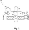
- FIG. 2 Other embodiments and/or aspects of this disclosure are shown in Fig. 2 .
- a method 100 of making a carbon rotor 300 includes, at block 102, providing a quantity of material.
- the method that follows can be dependent on the chosen material for the quantity of material.
- the method 100 further includes, at box 104, layering portions of the quantity of material atop one another to form a laminated structure, and at box 106, providing a resin infiltration between each layer of the laminated structure.
- the method 100 can further include, at box 108, heating (e.g., heat treating) the laminated structure.
- the method 100 can then include, at box 110 densifying the quantity of material (e.g., the laminated structure).
- the method can include forming the densified laminated structure into a disk shape, so as to form a rotor body shape, and at box 114, the method 100 can include carbonizing the densified disk.
- the method 100 includes forming (e.g., machining) a central bore in the disk configured to accept a rotor shaft and forming (e.g., machining) two or more apertures in the disk.
- the method 100 then further includes, at box 118, inserting magnets into the two or more apertures, respectively, such that each aperture includes one magnet.
- a method 200 can be similar to method 100, but differs because the quantity of material includes a quantity of an open carbon fiber needled preform, and a filler material.
- densifying 110 can include densifying the open fiber needled preform by chemical vapor infiltration (CVI).
- CVI chemical vapor infiltration
- the method 200 need not include the items performed in boxes 104, 106, 108, and instead, the material can go directly to densifying 110, and the remainder of the method 200 can be carried out as described above with respect to method 100.
- the rotor 300 can include a carbon rotor body 320 (e.g., a carbon fiber reinforced composite rotor body).
- a central bore 322 can be defined in the rotor body configured to accept a rotor shaft 324, and two or more rotor magnets 326 can be disposed in the rotor body 320 radially outward from the central bore 322 and circumferentially spaced from one another.
- the magnets 326 can be inserted into designated apertures 328 disposed in the rotor body 320. While shown in Fig.
- any suitable configuration of magnets 326 is contemplated herein.
- the magnets 326 could be arranged or oriented in a schach array, or standard configuration as appreciated by one having ordinary skill in the art.
- the magnets 326 can be arranged or oriented in a manner suitable for use in an axial flux motor, where the magnetic field is axially along the motor.
- the rotor 300 can include an even number of magnets 326, for example up to 30-40 magnets 326, however any suitable number of magnets 326 may be included depending on application.
- the carbon rotor body 302 can be formed (e.g., using one of methods 100, 200) from one or more of mesophase pitch, tar pitch, and/or PAN, or any suitable combination thereof.
- the rotor body 320 can include a densified, carbonized, laminated carbon preform disk, or in embodiments the rotor body 320 can include a densified, carbonized, carbon fiber preform disk.
- the preform can include carbon fibers in a two-dimensional or a three-dimensional arrangement.
- the two or more magnets 326 can include neodymium iron boron (NdFeB), samarium cobalt (SmCo), alnico, ceramic or ferrite magnets.
- Embodiments include a carbon fiber rotor, which provides for a different flow in the magnetic field, for example, directing heat outward from the rotor shaft. Embodiments allow for higher power to weight ratio in the electric motor.
- Embodiments of the carbon-carbon rotor allow for extracting heat generated by the rotor out of the rotor body at a better and/or faster rate than conventional cooling methods, more efficiently drawing the heat away from the magnets and out of the rotor body.
- embodiments include a rotor having a higher thermal diffusivity than typical rotors. Embodiments can improve eddy loss to zero or near zero due to eddy currents flowing through the rotor body.
- the material and manner in which the rotor is formed can be chosen based on different applications. For example, one method or starting material may be chosen over another when considering, desired thermodynamic properties, desired cooling rate, quantity of material needed or available, structural requirements, magnetic permeability, and the like for each given application.
- Embodiments can also provide for a much lighter rotor than traditional rotors which may be made from steel. Further, because the rotor will increase in size as its motor increases in size, the weigh savings offered by the carbon rotor disclosed herein is amplified. Additionally, weight savings are not limited to the rotor itself, but due to the improved cooling capability of the carbon rotor, additional cooling mechanisms may not need to be included in the motor system to cool the rotor, thus saving space and weight by eliminating the need for such additional components.
- any numerical values disclosed herein can be exact values or can be values within a range. Further, any terms of approximation (e.g., “about”, “approximately”, “around”) used in this disclosure can mean the stated value within a range. For example, in certain embodiments, the range can be within (plus or minus) 20%, or within 10%, or within 5%, or within 2%, or within any other suitable percentage or number as appreciated by those having ordinary skill in the art (e.g., for known tolerance limits or error ranges).
- a reference to "A and/or B", when used in conjunction with open-ended language such as “comprising” can refer, in one embodiment, to A only (optionally including elements other than B); in another embodiment, to B only (optionally including elements other than A); in yet another embodiment, to both A and B (optionally including other elements); etc.
Landscapes
- Engineering & Computer Science (AREA)
- Power Engineering (AREA)
- Manufacturing & Machinery (AREA)
- Permanent Field Magnets Of Synchronous Machinery (AREA)
Abstract
Description
- The present disclosure relates to rotors, and more particularly to carbon composite rotors for electric motors.
- Current electric motors are typically made out of metals, which can be heavy and require additional cooling in order to operate at higher capacities. Such rotors typically do not cool easily and can require additional cooling in order to operate at higher temperatures.
- However, there remains a need in the art for rotors in electric motors having reduced weight and improved temperature capabilities and cooling, removing the need for additional coolers. This disclosure provides a solution for this need.
- In accordance with at least one aspect of this disclosure, a method of making a carbon rotor includes, providing a quantity of material, densifying the quantity of material, and forming the densified material into a disk shape.
- In certain embodiments, the quantity of material can include a quantity of open carbon fiber fabric, and the method can further include layering portions of the quantity of fabric atop one another to form a laminated structure. In certain such embodiments, the method can include providing a resin infiltration between each layer of the laminated structure, and heating (e.g., heat treating) the laminated structure, such that densifying includes, densifying the laminated structure. In embodiments, the method includes carbonizing the disk, to form a carbon-carbon rotor, for example.
- In certain embodiments, the quantity of material can include an open carbon fiber needled preform, and a filler material. In certain such embodiments, densifying can include densifying the open fiber needled preform by chemical vapor infiltration (CVI). The method can further include carbonizing the disk.
- In certain embodiments, the quantity of material can include a quantity of mesophase pitch. In certain embodiments, the quantity of material can include a quantity of tar pitch. In certain embodiments, the quantity of material can include a quantity of Polyacrylonitrile (PAN). In certain embodiments, the quantity of material can include a quantity of any combination of mesophase pitch, tar pitch, and/or PAN, for example two or more of mesophase pitch, tar pitch, and/or PAN.
- In embodiments, the method also includes forming a central bore in the disk configured to accept a rotor shaft and two or more apertures in the disk. The two or more apertures can be formed in the disk radially outward from the central bore and circumferentially spaced from one another, and configured to accept two or more rotor magnets. The method can then further include inserting the two or more magnets into the two or more apertures, respectively, such that each aperture includes one magnet. In embodiments, the two or more magnets can include neodymium iron boron (NdFeB), samarium cobalt (SmCo), alnico, and ceramic or ferrite magnets.
- In accordance with at least one aspect of this disclosure, a rotor can include a carbon rotor body, a central bore defined in the rotor body configured to accept a rotor shaft, and two or more rotor magnets disposed in the rotor body radially outward from the central bore and circumferentially spaced from one another. In embodiments, the carbon rotor body can be formed from one or more of mesophase pitch, tar pitch, and/or PAN. In certain embodiments, the rotor body can include a densified, carbonized, laminated carbon fiber preform disk. In certain embodiments, the rotor body can include a densified, carbonized, carbon fiber preform disk. In embodiments, the one or more magnets can include neodymium iron boron (NdFeB), samarium cobalt (SmCo), alnico, and ceramic or ferrite magnets.
- These and other features of the embodiments of the subject disclosure will become more readily apparent to those skilled in the art from the following detailed description taken in conjunction with the drawings.
- So that those skilled in the art to which the subject disclosure appertains will readily understand how to make and use the devices and methods of the subject disclosure without undue experimentation, embodiments thereof will be described in detail herein below with reference to certain figures, wherein:
-
Fig. 1 is a box diagram of a method in accordance with this disclosure, showing a method of forming a rotor; and -
Fig. 2 is a partial perspective view of an embodiment of a rotor, showing the rotor formed by the method ofFig. 1 . - Reference will now be made to the drawings wherein like reference numerals identify similar structural features or aspects of the subject disclosure. For purposes of explanation and illustration, and not limitation, an illustrative view of an embodiment of a method in accordance with the disclosure is shown in
Fig. 1 and is designated generally byreference character 100. Other embodiments and/or aspects of this disclosure are shown inFig. 2 . - In accordance with at least one aspect of this disclosure, as shown in
Fig. 1 , amethod 100 of making a carbon rotor 300 (e.g., as shown inFig. 2 ) includes, atblock 102, providing a quantity of material. The method that follows can be dependent on the chosen material for the quantity of material. - In certain embodiments, if using a preformed open carbon fiber fabric for example, the
method 100 further includes, atbox 104, layering portions of the quantity of material atop one another to form a laminated structure, and atbox 106, providing a resin infiltration between each layer of the laminated structure. In certain such embodiments, themethod 100 can further include, atbox 108, heating (e.g., heat treating) the laminated structure. Themethod 100 can then include, atbox 110 densifying the quantity of material (e.g., the laminated structure). - At
box 112, the method can include forming the densified laminated structure into a disk shape, so as to form a rotor body shape, and atbox 114, themethod 100 can include carbonizing the densified disk. Atbox 116, themethod 100 includes forming (e.g., machining) a central bore in the disk configured to accept a rotor shaft and forming (e.g., machining) two or more apertures in the disk. Themethod 100 then further includes, atbox 118, inserting magnets into the two or more apertures, respectively, such that each aperture includes one magnet. - In certain embodiments, a
method 200 can be similar tomethod 100, but differs because the quantity of material includes a quantity of an open carbon fiber needled preform, and a filler material. In certain such embodiments, densifying 110 can include densifying the open fiber needled preform by chemical vapor infiltration (CVI). Here, themethod 200 need not include the items performed inboxes method 200 can be carried out as described above with respect tomethod 100. - Turning now to
Fig. 2 , in accordance with at least one aspect of this disclosure, therotor 300 can include a carbon rotor body 320 (e.g., a carbon fiber reinforced composite rotor body). Acentral bore 322 can be defined in the rotor body configured to accept arotor shaft 324, and two ormore rotor magnets 326 can be disposed in therotor body 320 radially outward from thecentral bore 322 and circumferentially spaced from one another. Themagnets 326 can be inserted into designated apertures 328 disposed in therotor body 320. While shown inFig. 2 as circumferentially spaced around a perimeter of therotor body 320, any suitable configuration ofmagnets 326 is contemplated herein. For example, themagnets 326 could be arranged or oriented in a halbach array, or standard configuration as appreciated by one having ordinary skill in the art. In embodiments, themagnets 326 can be arranged or oriented in a manner suitable for use in an axial flux motor, where the magnetic field is axially along the motor. In embodiments, therotor 300 can include an even number ofmagnets 326, for example up to 30-40magnets 326, however any suitable number ofmagnets 326 may be included depending on application. - In embodiments, the carbon rotor body 302 can be formed (e.g., using one of
methods 100, 200) from one or more of mesophase pitch, tar pitch, and/or PAN, or any suitable combination thereof. In embodiments, therotor body 320 can include a densified, carbonized, laminated carbon preform disk, or in embodiments therotor body 320 can include a densified, carbonized, carbon fiber preform disk. In embodiments, the preform can include carbon fibers in a two-dimensional or a three-dimensional arrangement. In embodiments, the two ormore magnets 326 can include neodymium iron boron (NdFeB), samarium cobalt (SmCo), alnico, ceramic or ferrite magnets. - Currently, typical electric motors having traditional rotors may not be able be adequately cooled using conventional methods such as air or water. Embodiments include a carbon fiber rotor, which provides for a different flow in the magnetic field, for example, directing heat outward from the rotor shaft. Embodiments allow for higher power to weight ratio in the electric motor.
- Embodiments of the carbon-carbon rotor allow for extracting heat generated by the rotor out of the rotor body at a better and/or faster rate than conventional cooling methods, more efficiently drawing the heat away from the magnets and out of the rotor body. Moreover, embodiments include a rotor having a higher thermal diffusivity than typical rotors. Embodiments can improve eddy loss to zero or near zero due to eddy currents flowing through the rotor body.
- As described, the material and manner in which the rotor is formed can be chosen based on different applications. For example, one method or starting material may be chosen over another when considering, desired thermodynamic properties, desired cooling rate, quantity of material needed or available, structural requirements, magnetic permeability, and the like for each given application.
- Embodiments can also provide for a much lighter rotor than traditional rotors which may be made from steel. Further, because the rotor will increase in size as its motor increases in size, the weigh savings offered by the carbon rotor disclosed herein is amplified. Additionally, weight savings are not limited to the rotor itself, but due to the improved cooling capability of the carbon rotor, additional cooling mechanisms may not need to be included in the motor system to cool the rotor, thus saving space and weight by eliminating the need for such additional components.
- Those having ordinary skill in the art understand that any numerical values disclosed herein can be exact values or can be values within a range. Further, any terms of approximation (e.g., "about", "approximately", "around") used in this disclosure can mean the stated value within a range. For example, in certain embodiments, the range can be within (plus or minus) 20%, or within 10%, or within 5%, or within 2%, or within any other suitable percentage or number as appreciated by those having ordinary skill in the art (e.g., for known tolerance limits or error ranges).
- The articles "a", "an", and "the" as used herein and in the appended claims are used herein to refer to one or to more than one (i.e., to at least one) of the grammatical object of the article unless the context clearly indicates otherwise. By way of example, "an element" means one element or more than one element.
- The phrase "and/or," as used herein in the specification and in the claims, should be understood to mean "either or both" of the elements so conjoined, i.e., elements that are conjunctively present in some cases and disjunctively present in other cases. Multiple elements listed with "and/or" should be construed in the same fashion, i.e., "one or more" of the elements so conjoined. Other elements may optionally be present other than the elements specifically identified by the "and/or" clause, whether related or unrelated to those elements specifically identified. Thus, as a non-limiting example, a reference to "A and/or B", when used in conjunction with open-ended language such as "comprising" can refer, in one embodiment, to A only (optionally including elements other than B); in another embodiment, to B only (optionally including elements other than A); in yet another embodiment, to both A and B (optionally including other elements); etc.
- As used herein in the specification and in the claims, "or" should be understood to have the same meaning as "and/or" as defined above. For example, when separating items in a list, "or" or "and/or" shall be interpreted as being inclusive, i.e., the inclusion of at least one, but also including more than one, of a number or list of elements, and, optionally, additional unlisted items. Only terms clearly indicated to the contrary, such as "only one of" or "exactly one of," or, when used in the claims, "consisting of," will refer to the inclusion of exactly one element of a number or list of elements. In general, the term "or" as used herein shall only be interpreted as indicating exclusive alternatives (i.e., "one or the other but not both") when preceded by terms of exclusivity, such as "either," "one of," "only one of," or "exactly one of."
- Any suitable combination(s) of any disclosed embodiments and/or any suitable portion(s) thereof are contemplated herein as appreciated by those having ordinary skill in the art in view of this disclosure.
- The embodiments of the present disclosure, as described above and shown in the drawings, provide for improvement in the art to which they pertain. While the apparatus and methods of the subject disclosure have been shown and described, those skilled in the art will readily appreciate that changes and/or modifications may be made thereto without departing from the scope of the subject disclosure. The scope of protection is defined by the appended claims.
Claims (15)
- A method of making a carbon rotor, comprising:providing a quantity of material;densifying the quantity of material; andforming the densified material into a disk shape.
- The method of claim 1, wherein the quantity of material includes a quantity of open carbon fiber fabric, and further comprising layering portions of the quantity of fabric atop one another to form a laminated structure.
- The method of claim 2, further comprising, providing a resin infiltration between each layer of the laminated structure; and optionally further comprising:
heating the laminated structure, wherein densifying includes, densifying the laminated structure; and optionally further comprising:
carbonizing the densified laminated structure. - The method of any preceding claim, wherein the quantity of material includes an open carbon fiber needled preform and a filler material.
- The method of claim 4, wherein densifying includes, densifying the filled open fiber needled preform by chemical vapor infiltration, CVI,; and optionally further comprising:
carbonizing the filled open fiber needled preform. - The method of any preceding claim, wherein the quantity of material includes a quantity of mesophase pitch; or wherein the quantity of material includes a quantity of tar pitch; or wherein the quantity of material includes a quantity of Polyacrylonitrile, PAN,.
- The method of any preceding claim, wherein the quantity of material includes a quantity of a combination of two or more of mesophase pitch, tar pitch, and/or PAN.
- The method of any preceding claim, further comprising:forming a central bore in the disk configured to accept a rotor shaft; andforming two or more apertures in the disk, radially outward from the central bore and circumferentially spaced from one another, configured to accept two or more rotor magnets.
- The method of claim 8, further comprising, inserting two or more magnets into the two or more apertures, respectively.
- The method of claim 9, wherein the two or more magnets include neodymium iron boron, NdFeB, samarium cobalt, SmCo, alnico, ceramic, or ferrite magnets.
- A rotor, comprising:a carbon rotor body (320);a central bore (322) defined in the rotor body, configured to accept a rotor shaft (324); andtwo or more rotor magnets (326) disposed in the rotor body radially outward from the central bore and circumferentially spaced from one another.
- The rotor of claim 11, wherein the carbon rotor body (320) is formed from one or more of mesophase pitch, tar pitch, and/or PAN.
- The rotor of claim 11 or 12, wherein the rotor body (320) includes a densified, carbonized, laminated carbon fiber preform disk.
- The rotor of claim 11, 12 or 13, wherein the rotor body (320) includes a densified, carbonized, carbon fiber preform disk.
- The rotor of any of claims 11 to 14, wherein the two or more magnets (326) include neodymium iron boron, NdFeB, samarium cobalt, SmCo, alnico, ceramic, or ferrite magnets.
Applications Claiming Priority (1)
| Application Number | Priority Date | Filing Date | Title |
|---|---|---|---|
| US17/715,671 US11901766B2 (en) | 2022-04-07 | 2022-04-07 | Carbon composite rotor for electric motors |
Publications (1)
| Publication Number | Publication Date |
|---|---|
| EP4258522A1 true EP4258522A1 (en) | 2023-10-11 |
Family
ID=85980745
Family Applications (1)
| Application Number | Title | Priority Date | Filing Date |
|---|---|---|---|
| EP23167046.4A Pending EP4258522A1 (en) | 2022-04-07 | 2023-04-06 | Carbon composite rotor for electric motors |
Country Status (2)
| Country | Link |
|---|---|
| US (1) | US11901766B2 (en) |
| EP (1) | EP4258522A1 (en) |
Citations (4)
| Publication number | Priority date | Publication date | Assignee | Title |
|---|---|---|---|---|
| EP2088347A1 (en) * | 2008-02-06 | 2009-08-12 | Honeywell International Inc. | CVD densified preform followed by VPI and RTM |
| DE102008050807A1 (en) * | 2008-10-08 | 2010-04-22 | Pro Diskus Ag | Rotor for an electric machine |
| US20150349596A1 (en) * | 2012-12-19 | 2015-12-03 | Leantec Motor Gmbh | Method for producing a rotor for an electric motor |
| DE102017204356A1 (en) * | 2017-03-16 | 2018-09-20 | Bayerische Motoren Werke Aktiengesellschaft | Rotor for a permanent magnet excited transverse flux machine |
Family Cites Families (4)
| Publication number | Priority date | Publication date | Assignee | Title |
|---|---|---|---|---|
| US4862763A (en) * | 1984-01-09 | 1989-09-05 | Ltv Aerospace & Defense Company | Method and apparatus for manufacturing high speed rotors |
| EP2112744A1 (en) | 2008-04-24 | 2009-10-28 | Magneti Marelli Holding S.p.A. | Multiphase synchronous electrical machine for converting kinetic energy into electrical energy and electrical energy into kinetic energy onboard a transport vehicle, and transport vehicle provided with said electrical machine |
| US20140167555A1 (en) | 2009-04-20 | 2014-06-19 | Eric Mims | Carbon fiber stator and rotor for an electric motor |
| US9729025B2 (en) | 2012-04-03 | 2017-08-08 | The Boeing Company | Open-core flywheel architecture |
-
2022
- 2022-04-07 US US17/715,671 patent/US11901766B2/en active Active
-
2023
- 2023-04-06 EP EP23167046.4A patent/EP4258522A1/en active Pending
Patent Citations (4)
| Publication number | Priority date | Publication date | Assignee | Title |
|---|---|---|---|---|
| EP2088347A1 (en) * | 2008-02-06 | 2009-08-12 | Honeywell International Inc. | CVD densified preform followed by VPI and RTM |
| DE102008050807A1 (en) * | 2008-10-08 | 2010-04-22 | Pro Diskus Ag | Rotor for an electric machine |
| US20150349596A1 (en) * | 2012-12-19 | 2015-12-03 | Leantec Motor Gmbh | Method for producing a rotor for an electric motor |
| DE102017204356A1 (en) * | 2017-03-16 | 2018-09-20 | Bayerische Motoren Werke Aktiengesellschaft | Rotor for a permanent magnet excited transverse flux machine |
Also Published As
| Publication number | Publication date |
|---|---|
| US20230327502A1 (en) | 2023-10-12 |
| US11901766B2 (en) | 2024-02-13 |
Similar Documents
| Publication | Publication Date | Title |
|---|---|---|
| Fang et al. | Rotor design and eddy-current loss suppression for high-speed machines with a solid-PM rotor | |
| Fang et al. | Rotor design for high-speed high-power permanent-magnet synchronous machines | |
| US8004140B2 (en) | Dovetail spoke internal permanent magnet machine | |
| US8018110B2 (en) | High speed internal permanent magnet machine and method of manufacturing the same | |
| EP1309074B1 (en) | Superconducting electromagnetic machine with tapered air gap and methods for cooling and forming an air gap in a superconducting machine | |
| Liu et al. | Application of an amorphous core to an ultra-high-speed sleeve-free interior permanent-magnet rotor | |
| EP2647875A2 (en) | Flexible magnet directional stiffening methods | |
| CN102377286A (en) | Motor and cooling systeem thereof | |
| EP2648318A2 (en) | Nested-rotor open-core flywheel | |
| EP1286448A1 (en) | Reverse flow stator ventilation system for superconducting synchronous machine | |
| EP2648319A2 (en) | Open-core flywheel construction | |
| US20160294229A1 (en) | Electric rotating machine with laterally magnetized magnets | |
| CN104702011A (en) | Rotor of rotating electrical machine and rotating electrical machine | |
| EP3082224B1 (en) | System and method for supporting laminations of synchronous reluctance motors | |
| US20060226724A1 (en) | Rotor for an electrical machine | |
| CN106300737A (en) | A kind of magnetic-suspension high-speed rotor structure for permanent magnet motor | |
| Krishnasamy et al. | Spray-formed hybrid-field traction motor | |
| US11901766B2 (en) | Carbon composite rotor for electric motors | |
| Darius Gnanaraj et al. | Materials for lightweight electric motors–a review | |
| EP2246962A2 (en) | High speed internal permanent magnet machine | |
| JP3670494B2 (en) | Electric machine | |
| Fang et al. | Rotor eddy-current loss minimization in high-speed PMSMs | |
| CN113991906A (en) | High-power high-speed permanent magnet motor rotor and cooling method thereof | |
| US20170110924A1 (en) | Rotor Cap for Electric Generators | |
| Geng et al. | Design of cooling system for high torque density permanent magnet synchronous motor based on heat pipe |
Legal Events
| Date | Code | Title | Description |
|---|---|---|---|
| PUAI | Public reference made under article 153(3) epc to a published international application that has entered the european phase |
Free format text: ORIGINAL CODE: 0009012 |
|
| STAA | Information on the status of an ep patent application or granted ep patent |
Free format text: STATUS: THE APPLICATION HAS BEEN PUBLISHED |
|
| AK | Designated contracting states |
Kind code of ref document: A1 Designated state(s): AL AT BE BG CH CY CZ DE DK EE ES FI FR GB GR HR HU IE IS IT LI LT LU LV MC ME MK MT NL NO PL PT RO RS SE SI SK SM TR |
|
| STAA | Information on the status of an ep patent application or granted ep patent |
Free format text: STATUS: REQUEST FOR EXAMINATION WAS MADE |
|
| 17P | Request for examination filed |
Effective date: 20240410 |
|
| RBV | Designated contracting states (corrected) |
Designated state(s): AL AT BE BG CH CY CZ DE DK EE ES FI FR GB GR HR HU IE IS IT LI LT LU LV MC ME MK MT NL NO PL PT RO RS SE SI SK SM TR |