EP4258510A1 - Battery replacement apparatus and battery replacement system - Google Patents
Battery replacement apparatus and battery replacement system Download PDFInfo
- Publication number
- EP4258510A1 EP4258510A1 EP22874195.5A EP22874195A EP4258510A1 EP 4258510 A1 EP4258510 A1 EP 4258510A1 EP 22874195 A EP22874195 A EP 22874195A EP 4258510 A1 EP4258510 A1 EP 4258510A1
- Authority
- EP
- European Patent Office
- Prior art keywords
- battery
- covering member
- connecting rod
- movable base
- connector
- Prior art date
- Legal status (The legal status is an assumption and is not a legal conclusion. Google has not performed a legal analysis and makes no representation as to the accuracy of the status listed.)
- Pending
Links
Images




Classifications
-
- B—PERFORMING OPERATIONS; TRANSPORTING
- B60—VEHICLES IN GENERAL
- B60S—SERVICING, CLEANING, REPAIRING, SUPPORTING, LIFTING, OR MANOEUVRING OF VEHICLES, NOT OTHERWISE PROVIDED FOR
- B60S5/00—Servicing, maintaining, repairing, or refitting of vehicles
- B60S5/06—Supplying batteries to, or removing batteries from, vehicles
-
- H—ELECTRICITY
- H02—GENERATION; CONVERSION OR DISTRIBUTION OF ELECTRIC POWER
- H02J—ELECTRIC POWER NETWORKS; CIRCUIT ARRANGEMENTS OR SYSTEMS FOR SUPPLYING OR DISTRIBUTING ELECTRIC POWER; SYSTEMS FOR STORING ELECTRIC ENERGY
- H02J7/00—Circuit arrangements for charging or discharging batteries or for supplying loads from batteries
- H02J7/70—Circuit arrangements for charging or discharging batteries or for supplying loads from batteries characterised by the mechanical construction
-
- H—ELECTRICITY
- H02—GENERATION; CONVERSION OR DISTRIBUTION OF ELECTRIC POWER
- H02J—ELECTRIC POWER NETWORKS; CIRCUIT ARRANGEMENTS OR SYSTEMS FOR SUPPLYING OR DISTRIBUTING ELECTRIC POWER; SYSTEMS FOR STORING ELECTRIC ENERGY
- H02J7/00—Circuit arrangements for charging or discharging batteries or for supplying loads from batteries
- H02J7/70—Circuit arrangements for charging or discharging batteries or for supplying loads from batteries characterised by the mechanical construction
- H02J7/751—Circuit arrangements for charging or discharging batteries or for supplying loads from batteries characterised by the mechanical construction concerning the insertion or the connection of the batteries
-
- B—PERFORMING OPERATIONS; TRANSPORTING
- B60—VEHICLES IN GENERAL
- B60L—PROPULSION OF ELECTRICALLY-PROPELLED VEHICLES; SUPPLYING ELECTRIC POWER FOR AUXILIARY EQUIPMENT OF ELECTRICALLY-PROPELLED VEHICLES; ELECTRODYNAMIC BRAKE SYSTEMS FOR VEHICLES IN GENERAL; MAGNETIC SUSPENSION OR LEVITATION FOR VEHICLES; MONITORING OPERATING VARIABLES OF ELECTRICALLY-PROPELLED VEHICLES; ELECTRIC SAFETY DEVICES FOR ELECTRICALLY-PROPELLED VEHICLES
- B60L3/00—Electric devices on electrically-propelled vehicles for safety purposes; Monitoring operating variables, e.g. speed, deceleration or energy consumption
- B60L3/0023—Detecting, eliminating, remedying or compensating for drive train abnormalities, e.g. failures within the drive train
- B60L3/0046—Detecting, eliminating, remedying or compensating for drive train abnormalities, e.g. failures within the drive train relating to electric energy storage systems, e.g. batteries or capacitors
-
- B—PERFORMING OPERATIONS; TRANSPORTING
- B60—VEHICLES IN GENERAL
- B60L—PROPULSION OF ELECTRICALLY-PROPELLED VEHICLES; SUPPLYING ELECTRIC POWER FOR AUXILIARY EQUIPMENT OF ELECTRICALLY-PROPELLED VEHICLES; ELECTRODYNAMIC BRAKE SYSTEMS FOR VEHICLES IN GENERAL; MAGNETIC SUSPENSION OR LEVITATION FOR VEHICLES; MONITORING OPERATING VARIABLES OF ELECTRICALLY-PROPELLED VEHICLES; ELECTRIC SAFETY DEVICES FOR ELECTRICALLY-PROPELLED VEHICLES
- B60L53/00—Methods of charging batteries, specially adapted for electric vehicles; Charging stations or on-board charging equipment therefor; Exchange of energy storage elements in electric vehicles
- B60L53/80—Exchanging energy storage elements, e.g. removable batteries
-
- Y—GENERAL TAGGING OF NEW TECHNOLOGICAL DEVELOPMENTS; GENERAL TAGGING OF CROSS-SECTIONAL TECHNOLOGIES SPANNING OVER SEVERAL SECTIONS OF THE IPC; TECHNICAL SUBJECTS COVERED BY FORMER USPC CROSS-REFERENCE ART COLLECTIONS [XRACs] AND DIGESTS
- Y02—TECHNOLOGIES OR APPLICATIONS FOR MITIGATION OR ADAPTATION AGAINST CLIMATE CHANGE
- Y02T—CLIMATE CHANGE MITIGATION TECHNOLOGIES RELATED TO TRANSPORTATION
- Y02T10/00—Road transport of goods or passengers
- Y02T10/60—Other road transportation technologies with climate change mitigation effect
- Y02T10/70—Energy storage systems for electromobility, e.g. batteries
-
- Y—GENERAL TAGGING OF NEW TECHNOLOGICAL DEVELOPMENTS; GENERAL TAGGING OF CROSS-SECTIONAL TECHNOLOGIES SPANNING OVER SEVERAL SECTIONS OF THE IPC; TECHNICAL SUBJECTS COVERED BY FORMER USPC CROSS-REFERENCE ART COLLECTIONS [XRACs] AND DIGESTS
- Y02—TECHNOLOGIES OR APPLICATIONS FOR MITIGATION OR ADAPTATION AGAINST CLIMATE CHANGE
- Y02T—CLIMATE CHANGE MITIGATION TECHNOLOGIES RELATED TO TRANSPORTATION
- Y02T10/00—Road transport of goods or passengers
- Y02T10/60—Other road transportation technologies with climate change mitigation effect
- Y02T10/7072—Electromobility specific charging systems or methods for batteries, ultracapacitors, supercapacitors or double-layer capacitors
Definitions
- the present application relates to the technical field of battery swapping for power consuming devices, and in particular to a battery swap device and a battery swap system.
- the battery swap device removes an under-charge battery (i.e., a battery to be charged) from a power consuming device, transfers the under-charge battery to a charging device for replenishment with electric energy, and transfers a full-charge battery (i.e., a fully charged battery) to the power consuming device for installation. During the transfer process, the battery is exposed and thus easily damaged, thereby reducing the safety of the battery.
- an under-charge battery i.e., a battery to be charged
- a charging device for replenishment with electric energy
- a full-charge battery i.e., a fully charged battery
- the present application aims to provide a battery swap device and a battery swap system, so as to solve the problem in the prior art.
- a battery swap device comprising:
- the protective apparatus is provided on the movable base.
- the drive mechanism of the protective apparatus drives the covering member to cover the connector of the battery, and the covering member protects the connector to prevent dust and water from entering the connector.
- the drive mechanism drives the covering member to move away from the connector to enable the battery to leave the movable base.
- the covering member automatically protects the connector of the battery under the action of the drive mechanism, thereby effectively improving the safety of the battery and prolonging the service life of the connector.
- the protective apparatus has an extended state in which the covering member extends out of the movable base to cover the connector, and a retracted state in which the covering member is retracted to the movable base.
- the drive mechanism drives the covering member to leave the connector of the battery and drives the covering member to retract to the movable base, so that the whole battery swap device takes up a small space.
- the movable base has an accommodating space, and in the retracted state, the covering member is at least partially located in the accommodating space.
- the covering member when retracted, is at least partially located in the accommodating space, with only part of the covering member exposed or not exposed to the outside of the movable base, so that the battery swap device is of a more compact structure, has reduced space occupied by the battery swap device, and also has a function of protecting the covering member to prevent the covering member from being damaged by interference with foreign objects.
- the covering member in the retracted state, is located on a side surface of the movable base; and in the extended state, the covering member is located above the movable base.
- the covering member is retracted to the side surface of the movable base and does not occupy the space above the movable base, so that when the battery is placed on the movable base, there is no need to consider avoiding the covering member.
- Such a configuration will not affect the pick and place of the battery.
- the covering member on the side surface is less likely to interfere with the power consuming device.
- one end of the drive mechanism is mounted to the movable base, and the covering member is connected to the other end of the drive mechanism.
- the covering member is directly connected to the movable base by means of the drive mechanism, so that the connection structure is simple.
- the drive mechanism comprises a drive member, a first connecting rod and a second connecting rod, one end of the first connecting rod and one end of the second connecting rod being separately hinged to the movable base, the other end of the first connecting rod and the other end of the second connecting rod being separately hinged to the covering member, and the drive member being configured to drive the first connecting rod to rotate around a hinge point of the first connecting rod to the movable base.
- the movable base, the first connecting rod, the covering member and the second connecting rod are sequentially hinged to form a four-connecting-rod mechanism which guarantees, with a simple structure, smooth movement of the covering member along a set route to ensure that the covering member covers the connector.
- the drive mechanism further comprises a first rotating shaft, one end of the first connecting rod being hinged to the movable base by means of the first rotating shaft, and the first rotating shaft being fixed to the first connecting rod; and the drive mechanism further comprises a gear and a rack which mesh with each other, the gear being fixed to the first rotating shaft, and the drive member being configured to drive the rack to move so as to swing the first connecting rod by means of the gear.
- a linear motion is converted into rotation by means of the gear and the rack and then swings the first connecting rod to drive the covering member.
- the driving can be implemented with an ordinary pneumatic cylinder, electric cylinder, etc., and does not require the use of a high-torque rotary drive device, so as to have low requirements on the drive device.
- the drive mechanism further comprises a sliding rail and a slider which cooperate with each other, the slider being fixedly connected to the movable base, and the rack being fixedly connected to the sliding rail.
- the sliding rail and the slider cooperate for guiding the rack to move stably, ensuring the drive effect.
- the covering member is a cover-shaped member configured to cover over the connector.
- the cover-shaped structure shields the connector in all directions to achieve comprehensive protection and high safety.
- the covering member comprises a top plate, an end plate and two side plates, the two side plates being connected to opposite sides of the top plate, the end plate being provided at one end of the top plate and connected to the top plate and the two side plates, and the side of the covering member opposite the top plate and the side of the covering member opposite the end plate being both open.
- the cover-shaped structure in addition to the opening opposite the top plate, the cover-shaped structure further has an opening opposite the end plate.
- the side opposite the end plate needs to pass over the connector to reach the other side of the connector. Providing the opening on this side can prevent interference between the cover-shaped structure and the connector. Since there is no interference, the movement path of the covering member can be set relatively close to the movable base, so that the protective apparatus requires a relatively small operating space and can thus conveniently operate in a narrow space under a vehicle.
- the battery swap device further comprises:
- the first detection unit and the second detection unit are provided to obtain state information of the covering member, so as to eliminate abnormality in a timely manner to ensure the safety of the battery during the transfer process.
- a battery swap system comprising:
- the battery swap device moves between the battery swap platform and the battery pick-and-place device to transfer a battery.
- the connector is protected by the protective apparatus during the movement of the battery swap device, so that the battery is not easily damaged.
- a plurality of means two or more (including two), similarly the term “a plurality of groups” means two or more groups (including two groups), and the term “a plurality of pieces” means two or more pieces (including two pieces).
- the technical terms “mounting”, “mutual connection”, “connection”, “fixing”, etc. should be understood in a broad sense, for example, they may be a fixed connection, a detachable connection, or an integrated connection; may be a mechanical connection or an electrical connection; and may be a direct connection or an indirect connection through an intermediate medium, and may be communication between interiors of two elements or interaction between the two elements.
- mounting may be a fixed connection, a detachable connection, or an integrated connection
- the specific meaning of the above terms in the embodiments of the present application can be understood according to specific situations.
- a power consuming device When the electric energy is exhausted, a power consuming device is always connected to a charging device for replenishment with electric energy.
- a charging device For example, an electric vehicle can be connected to a charging pile for charging.
- the battery replacement can achieve faster replenishment with electric energy.
- a special battery swap system for battery replacement which is provided with a battery pick-and-place device and a movable battery swap device.
- the battery pick-and-place device is configured to place a battery on the battery swap device, or take away the battery on the battery swap device and transfer the battery to a charging device for charging.
- the battery swap device carries the battery, moves between a power consuming device and the battery pick-and-place device, i.e., transfers the battery between the power consuming device and the battery pick-and-place device, and installs the battery to the power consuming device or removes the battery from the power consuming device.
- a connector of the battery fits with a connector of the power consuming device in a plug-in manner to output electric energy to the power consuming device; and when the battery is being charged, the connector of the battery fits with a connector of the charging device in a plug-in manner to output electric energy to the battery.
- a short circuit occurs when the battery is connected to the power consuming device, and there is also a short circuit when the battery is connected to the charging device for charging, resulting in a safety risk.
- the battery cannot normally output or input electric energy due to poor electric connection with the power consuming device and the charging device.
- the inventors have found that the above situations are mostly caused by water and dust entering the connector of the battery.
- the inventors have noticed that the connector of the battery is usually exposed during the transfer process of the battery by the battery swap device and thus prone to dust or water ingress. Dust ingress easily leads to a poor electric connection, water ingress easily leads to a short circuit, and water ingress also makes it easier for dust to adhere to the connector and thus affects the stability of connection, resulting in reduced safety of the battery and reduced electric current transfer stability.
- the present application provides a battery swap device, comprising a movable base and a protective apparatus.
- the protective apparatus is provided on the movable base and configured to protect a connector.
- the protective apparatus comprises a drive mechanism and a covering member.
- the drive mechanism is configured to drive the covering member to move to cover or uncover the connector.
- the drive mechanism drives the covering member to cover the connector so as to prevent dust and water from entering the connector.
- the drive mechanism drives the covering member to leave the battery, so that the connector is exposed again so as to connect the connector of the battery to a current input port of the power consuming device.
- the covering member automatically protects the connector of the battery under the action of the drive mechanism, so as to effectively solve the problem of water and dust entering the connector, thereby improving the safety of the battery and the electric current transfer stability.
- a battery installation position refers to a space formed in the power consuming device for accommodating a battery, e.g., an upward recess formed in a chassis of a vehicle, the recess serves as the battery installation position for accommodating the battery, and the connector of the power consuming device is disposed in the battery installation position.
- the battery swap device and the battery swap system disclosed in the embodiments of the present application can be used for, but not limited to, replacing batteries of vehicles, and can also be used for replacing batteries of ships, aircrafts, and other power consuming devices, such as electric toys, electric tools, battery cars, electric vehicles, steamships and spacecrafts.
- the electric toys may include stationary or mobile toys, for example, game consoles, electric car toys, electric ship toys, electric airplane toys, etc.
- the electric tools may include a stationary or mobile electric tools, for example, electric machine tools, electric sweeping vehicles, etc.
- the spacecrafts may include airplanes, rockets, aerospace planes, spaceships, etc.
- the battery swap device and the battery swap system are described below, taking the power consuming device being a vehicle as an example.
- the battery swap system comprises a battery swap device 1000 and a battery pick-and-place device 4000.
- the battery swap system further comprises a charging device (not shown in the figure), and the charging device is configured to store a battery 2000 and charge the battery 2000.
- the battery pick-and-place device 4000 may be a robot, a stacker, etc.
- the battery pick-and-place device 4000 is provided with a fork 4001 (the fork 4001 may also be replaced with a mechanical arm). Using the fork 4001, an under-charge battery 2000 on the battery swap device 1000 is removed and placed into the charging device for recycling, and a full-charge battery 2000 is taken out from the charging device and placed on the battery swap device 1000.
- the battery swap device 1000 moves between the vehicle and the battery pick-and-place device 4000.
- the battery swap device 1000 removes the under-charge battery 2000 from the vehicle and transfers same to the battery pick-and-place device 4000.
- the battery pick-and-place device 4000 takes away the under-charge battery 2000 from the battery swap device 1000 and places same into the charging device, and takes out the full-charge battery 2000 from the charging device and places same onto the battery swap device 1000, and then the battery swap device 1000 transfers the full-charge battery 2000 to the vehicle and installs same to the vehicle.
- the battery swap system may further comprise a battery swap platform 3000 for parking the vehicle.
- the battery swap device 1000 moves between the battery swap platform 3000 and the battery pick-and-place device 4000.
- the battery swap platform 3000 is configured to lift the vehicle as a whole, the vehicle is located above the battery swap platform 3000, an avoidance opening 3001 is formed in the battery swap platform 3000, an installation position (not shown in the figure) of the battery 2000 of the vehicle corresponds to the avoidance opening 3001, the battery swap device 1000 is parked below the avoidance opening 3001 of the vehicle, and the battery 2000 on the battery swap device 1000 passes through the avoidance opening 3001 and is then installed in the installation position of the battery 2000 of the vehicle, or the battery 2000 in the installation position of the battery 2000 of the vehicle is removed, passes through the avoidance opening 3001, and then falls onto the battery swap device 1000.
- the battery swap device 1000 comprises a movable base 100 and a protective apparatus 200.
- the movable base 100 is configured to carry the battery 2000, and the battery 2000 is provided with a connector 2001 configured to transfer electric energy.
- the protective apparatus 200 is provided on the movable base 100 and configured to protect the connector 2001.
- the protective apparatus 200 comprises a drive mechanism and a covering member 220. The drive mechanism is configured to drive the covering member 220 to move to cover or uncover the connector 2001.
- the movable base 100 is an apparatus configured to move between the battery pick-and-place device 4000 and the vehicle, and is also an apparatus configured to carry the battery 2000 during the transfer process. In other words, the movable base 100 moves between the battery pick-and-place device 4000 and the vehicle to transfer the battery 2000.
- the movable base 100 may be a trolley driven by a motor. The trolley moves between the battery pick-and-place device 4000 and the vehicle along a set path. A track may be provided between the battery pick-and-place device 4000 and the vehicle to set the path. The trolley is mounted to the track and moves along the track.
- the connector 2001 of the battery 2000 When the battery 2000 is located on the movable base 100, the connector 2001 of the battery 2000 usually faces upwards so as to be connected to the connector 2001 in the installation position of the battery 2000 on a chassis of the vehicle.
- the protective apparatus 200 is an apparatus for protecting the connector 2001 of the battery 2000, and the protective apparatus 200 is provided on the movable base 100.
- the protective apparatus 200 protects the connector 2001 of the battery 2000 from external dust, water and other substances.
- the covering member 220 is a component of the protective apparatus 200 for covering the connector 2001.
- the covering member 220 covering the connector 2001 means that the protective apparatus 200 at least shields an upper end surface of the connector 2001 by means of the covering member 220 such that the end of the connector 2001 to be connected to the power consuming device and the charging device is prevented from contacting with water, for example, the covering member 220 can protect the connector 2001 from getting wet on a rainy day, and when there is an opening in the upper end surface of the connector 2001, it is possible to prevent water from entering the interior of the connector 2001 through the opening.
- the covering member 220 uncovering the connector 2001 means that the covering member 220 moves away from the above of the connector 2001, so that the power consuming device is connected to the charging device by means of the connector 2001.
- the drive mechanism is a component for providing power to the covering member 220 so as to enable the covering member 220 to switch between a position where the connector 2001 is covered and a position where the connector 2001 is uncovered.
- the protective apparatus 200 is provided on the movable base 100, the drive mechanism of the protective apparatus 200 drives the covering member 220 to cover the connector 2001 of the battery 2000, and during the transfer process of the battery 2000 by the movable base 100, the covering member 220 protects the connector 2001 to prevent dust and water from entering the connector 2001.
- the drive mechanism drives the covering member 220 to move away from the connector 2001 to enable the battery 2000 to leave the movable base 100.
- the covering member 220 automatically protects the connector 2001 of the battery 2000 under the action of the drive mechanism, thereby effectively improving the safety of the battery 2000 and prolonging the service life of the connector 2001.
- the protective apparatus 200 has an extended state in which the covering member 220 extends out of the movable base 100 to cover the connector 2001, and a retracted state in which the covering member 220 is retracted to the movable base 100.
- the drive mechanism can drive the covering member 220 to extend or retract. After the battery 2000 is placed on the movable base 100, the drive mechanism drives the covering member 220 to extend to cover the connector 2001 of the battery 2000; and after the movable base 100 transfers the battery 2000 in position, the drive mechanism drives the covering member 220 to be retracted to the movable base 100 to provide a space for the battery 2000 to leave the movable base 100.
- the drive mechanism drives the covering member 220 to leave the connector 2001 of the battery 2000 and drives the covering member 220 to be retracted to the movable base 100, so that the whole battery swap device 1000 takes up a small space.
- the number of the protective apparatuses 200 is not limited in the present application.
- the movable base 100 is provided with one protective apparatus 200.
- the movable base 100 is provided with two protective apparatuses 200, and the two protective apparatuses 200 may be disposed symmetrically about the movable base 100 to respectively protect the two batteries 2000 carried on the movable base 100, or protect the two connectors 2001 of one battery 2000.
- the movable base 100 is provided with an accommodating space 120.
- the covering member 220 is at least partially located in the accommodating space 120.
- the accommodating space 120 described above is a space within an outer contour of the movable base 100, and the covering member 220 is embedded into the movable base 100 when the movable base 100 is located within the accommodating space 120.
- the covering member 220 when retracted, is at least partially located in the accommodating space 120, with only part of the covering member exposed or not exposed to an outside of the movable base 100, so that the battery swap device 1000 is of a more compact structure, has reduced space occupied by the battery swap device 1000, and also has a function of protecting the covering member 220 to prevent the covering member 220 from being damaged by interference with foreign objects.
- the covering member 220 in the extended state, is located above the movable base 100; and as shown in FIGS. 4 , 7 and 8 , in the retracted state, the covering member 220 is located on a side surface of the movable base 100.
- the movable base 100 generally comprises a top surface, a bottom surface and a side surface.
- the top surface and the bottom surface are opposite in the direction of gravity, the top surface is configured to place the battery 2000, the bottom surface is provided with walking wheels, and the side surface is located between the top surface and the bottom surface and connects the top surface to the bottom surface.
- the covering member 220 is retracted to the side surface of the movable base 100 by means of the drive mechanism.
- the drive mechanism lifts the covering member 220 above of the battery 2000 and covers the connector 2001 of the battery 2000 from above.
- the covering member 220 is retracted to the side surface of the movable base 100 and does not occupy the space above the movable base 100, so that when the battery 2000 is placed on the movable base 100, there is no need to consider avoiding the covering member 220. Such a configuration will not affect the pick and place of the battery 2000.
- the covering member 220 on the side surface is less likely to interfere with the power consuming device.
- the covering member 220 in the retracted state, may also be located on the top surface or the bottom surface of the movable base 100, which is not limited by the present application.
- one end of the drive mechanism is mounted to the movable base 100, and the covering member 220 is connected to the other end of the drive mechanism.
- the drive mechanism is similar to a mechanical arm, and the covering member 220 is connected to an output end of the drive mechanism, so that the covering member 220 can be driven by the drive mechanism to move with multiple degrees of freedom so as to cover and uncover the connector 2001.
- the drive mechanism comprises a drive member 210, a first connecting rod 2121 and a second connecting rod 2122.
- One end of the first connecting rod 2121 and one end of the second connecting rod 2122 are separately hinged to the movable base 100, and the other end of the first connecting rod 2121 and the other end of the second connecting rod 2122 are separately hinged to the covering member 220.
- the drive member 210 is configured to drive the first connecting rod 2121 to rotate around a hinge point of the first connecting rod 2121 to the movable base 100.
- the movable base 100, the first connecting rod 2121, the covering member 220 and the second connecting rod 2122 are sequentially hinged.
- the first connecting rod 2121 is a driving member
- the first connecting rod 2121 drives the covering member 220 and the second connecting rod 2122 to rotate
- the first connecting rod 2121 and the second connecting rod 2122 constrain the covering member 220, so as to guarantee the smooth movement of the covering member 220 and ensure the positional consistency of each covering by the covering member 220 to not interfere with the connector 2001.
- the movable base 100 comprises a base body 110, a third connecting rod 130, and an elastic resetting member 140.
- the third connecting rod 130 and the first connecting rod 2121 are both hinged to the base body 110, and their hinge axes are collinear.
- One end of the second connecting rod 2122 is hinged to the covering member 220, and the other end of the second connecting rod 2122 is hinged to the third connecting rod 130.
- the elastic resetting member 140 is configured to maintain the third connecting rod 130 in an initial position.
- the first connecting rod 2121, the covering member 220, the second connecting rod 2122 and the third connecting rod 130 firstly form a parallelogram connecting rod mechanism, and during clockwise rotation of the first connecting rod 2121, the angle of the covering member 220 remains unchanged, and the covering member 220 only translates but does not rotate.
- the first connecting rod 2121 drives the third connecting rod 130 to rotate clockwise against an elastic force of the elastic resetting member 140 when the first connecting rod 2121 rotates clockwise to abut against the third connecting rod 130, and at this time, the connecting rod mechanism degrades from the parallelogram connecting rod mechanism to a triangular connecting rod mechanism.
- the connecting rod mechanism as a whole follows the third connecting rod 130 to rotate around a hinge axis of the third connecting rod 130 and the base body 110, and the angle of the covering member 220 changes.
- clockwise refers to a clockwise direction ⁇ shown in the figures.
- the first connecting rod 2121 rotates in a counterclockwise direction ⁇ , and the connecting rod mechanism is transformed from the triangular connecting rod mechanism to the parallelogram connecting rod mechanism.
- the third connecting rod 130 is provided with a limiting boss 131, and when the first connecting rod 2121 rotates clockwise to abut against the limiting boss 131, the first connecting rod 2121 drives the third connecting rod 130 to rotate clockwise against the elastic force of the elastic resetting member 140, and at this time, the connecting rod mechanism degrades from the parallelogram connecting rod mechanism to the triangular connecting rod mechanism.
- the elastic resetting member 140 may be a torsion spring, with one end of the torsion spring abutting against the third connecting rod 130, and the other end abutting against the base body 110, so that the third connecting rod 130 is maintained in an initial position.
- the drive mechanism further comprises a first rotating shaft 2123, one end of the first connecting rod 2121 being hinged to the movable base 100 by means of the first rotating shaft 2123, and the first rotating shaft 2123 being fixed to the first connecting rod 2121; and the drive mechanism further comprises a gear 2132 and a rack 2131 which mesh with each other, the gear 2132 being fixed to the first rotating shaft 2123, and the drive member 210 being configured to drive the rack 2131 to move to swing the first connecting rod 2121 by means of the gear 2132.
- the first rotating shaft 2123 may be fixed to the first connecting rod 2121 by means of welding or integral forming.
- the gear 2132 may be fixed to the first rotating shaft 2123 by means of interference fitting or integral forming, the rack 2131 meshes with the gear 2132, and when the drive member 210 drives the rack 2131 to move in its extension direction, the rack 2131 drives the gear 2132 to rotate to swing the first connecting rod 2121 so as to move the covering member 220.
- a linear motion is converted into rotation by means of the gear 2132 and the rack 2131 and then swings the first connecting rod 2121 to drive the covering member 220.
- the driving can be implemented with an ordinary pneumatic cylinder, electric cylinder, etc., and does not require the use of a high-torque rotary drive member 210, so as to have low requirements on the drive member 210.
- the drive mechanism further comprises a connecting member 211, and an output end of the drive member 210 is connected to the rack 2131 by means of the connecting member 211.
- the drive mechanism further comprises a sliding rail 2133 and a slider 2134 which cooperate with each other, the slider 2134 being fixedly connected to the movable base 100, and the rack 2131 being fixedly connected to the sliding rail 2133.
- the slider 2134 is fixed to the movable base 100, and the sliding rail 2133 extends in an extension direction of the rack 2131 and forms a sliding fit with the slider 2134, the sliding rail 2133 and the slider 2134 slide relative to each other when the drive member 210 drives the rack 2131 to move, and the sliding rail 2133 and the slider 2134 cooperate for guiding the rack 2131 to move stably, ensuring a drive effect.
- the covering member 220 is a cover-shaped member configured to cover over the connector 2001.
- the cover-shaped member described above refers to a component having an accommodating space 120 and an opening that is in communication with the accommodating space 120.
- the cover-shaped structure shields the connector 2001 in all directions to achieve comprehensive protection and high safety.
- the covering member 220 comprises a top plate 221, an end plate 222 and two side plates 223, the two side plates 223 being connected to opposite sides of the top plate 221, the end plate 222 being provided at one end of the top plate 221 and connected to the top plate 221 and the two side plates 223, and the side of the covering member 220 opposite the top plate 221 and the side of the covering member opposite the end plate 222 being both open.
- the cover-shaped structure in addition to a first opening 224 opposite the top plate 221, the cover-shaped structure further has a second opening 225 opposite the end plate 222.
- the covering member 220 extends out of the movable base 100 to cover the connector 2001, the side opposite the end plate 222 needs to pass over the connector 2001 to reach the other side of the connector 2001. Providing the opening on this side can prevent interference between the cover-shaped structure and the connector 2001. Since there is no interference, the movement path of the covering member 220 can be set relatively close to the movable base 100, so that the protective apparatus 200 requires a relatively small operating space and can thus conveniently operate in a narrow space under a vehicle.
- the battery swap device 1000 further comprises: a first detection unit 300 configured to output a first signal when the protective apparatus 200 is detected to be in the extended state; and/or a second detection unit 400 configured to output a second signal when the protective apparatus 200 is detected to be in the retracted state.
- the first detection unit 300 detects that the protective apparatus 200 extends in position and then outputs the first signal to provide, to a control system, a feedback that the covering member 220 covers the connector 2001, and then the transfer of the battery 2000 can be started.
- the second detection unit 400 detects that the protective apparatus 200 is retracted in position and then outputs the second signal to provide, to the control system, a feedback that the covering member 220 is removed from the connector 2001, and then the battery 2000 can be taken away from the movable base 100.
- the first detection unit 300 and the second detection unit 400 may be in-position sensors, and the first detection unit 300 and the second detection unit 400 are both mounted on the base body 110.
- the first detection unit 300 is configured to detect the connecting member 211, and the connecting member 211 triggers the first detection unit 300 to output the first signal when the connecting member 211 moves to a position corresponding to the extended state of the protective apparatus 200.
- the second detection unit 400 is configured to detect the second connecting rod 2122, and the second connecting rod 2122 triggers the second detection unit 400 to output the second signal when the second connecting rod 2122 moves to a position corresponding to the retracted state of the protective apparatus 200.
- the first detection unit 300 and the second detection unit 400 are provided to obtain state information of the covering member 220, so as to eliminate abnormality in a timely manner to ensure the safety of the battery 2000 during the transfer process.
- a battery swap system comprising a battery swap platform 3000, a battery pick-and-place device 4000, and a battery swap device 1000 according to the embodiments of the present application.
- the battery swap platform 3000 is configured to carry a power consuming device that has a battery 2000 to be replaced.
- the battery swap device 1000 moves between the battery swap platform 3000 and the battery pick-and-place device 4000 to transfer the battery 2000.
- the battery pick-and-place device 4000 may be a robot, a stacker, etc.
- the battery pick-and-place device 4000 is provided with a fork 4001 (the fork 4001 may also be replaced with a mechanical arm). Using the fork 4001, an under-charge battery 2000 on the battery swap device 1000 is removed and placed into the charging device for recycling, and a full-charge battery 2000 is taken out from the charging device and placed on the battery swap device 1000.
- the present application provides a battery swap device 1000.
- the battery swap device 1000 comprises a movable base 100 and a protective apparatus 200.
- the protective apparatus 200 is provided on the movable base 100 and configured to protect the connector 2001.
- the protective apparatus 200 comprises a drive mechanism and a covering member 220.
- the drive mechanism is configured to drive the covering member 220 to cover or uncover the connector 2001.
- the drive mechanism comprises a drive member 210, a first rotating shaft 2123, a gear 2132, a rack 2131, a sliding rail 2133, a slider 2134, a first connecting rod 2121 and a second connecting rod 2122.
- the movable base 100 comprises a base body 110, a third connecting rod 130 and an elastic resetting member 140.
- One end of the first connecting rod 2121 and one end of the third connecting rod 130 are both hinged to the base body 110 and their hinge axes are collinear, the other end of the first connecting rod 2121 is hinged to the covering member 220, one end of the second connecting rod 2122 is hinged to the covering member 220, and the other end of the second connecting rod 2122 is hinged to the third connecting rod 130.
- the elastic resetting member 140 is a torsion spring, with one end of the torsion spring abutting against a fourth connecting rod, and the other end abutting against the base body 110, so that the fourth connecting rod is maintained in an initial position.
- the first rotating shaft 2123 is fixed to the first connecting rod 2121.
- the gear 2132 is fixed to the first rotating shaft 2123, and the rack 2131 meshes with the gear 2132.
- the drive member 210 is a pneumatic cylinder, with an output end of the pneumatic cylinder being connected to the rack 2131 by means of the connecting member 211.
- the slider 2134 is fixedly connected to the base body 110, the rack 2131 is fixedly connected to the sliding rail 2133, and the slider 2134 and the slider 2134 cooperate with each other.
- the covering member 220 comprises a top plate 221, an end plate 222 and two side plates 223, the two side plates 223 being connected to opposite sides of the top plate 221, the end plate 222 being provided at one end of the top plate 221 and connected to the top plate 221 and the two side plates 223, and the side of the covering member 220 opposite the top plate 221 and the side of the covering member opposite the end plate 222 being both open.
Landscapes
- Engineering & Computer Science (AREA)
- Power Engineering (AREA)
- Mechanical Engineering (AREA)
- Transportation (AREA)
- Life Sciences & Earth Sciences (AREA)
- Sustainable Development (AREA)
- Sustainable Energy (AREA)
- Charge And Discharge Circuits For Batteries Or The Like (AREA)
- Arrangement Or Mounting Of Propulsion Units For Vehicles (AREA)
- Battery Mounting, Suspending (AREA)
- Electric Propulsion And Braking For Vehicles (AREA)
Abstract
Description
- The present application claims priority to
Chinese patent application no. 202111166643.X, entitled "BATTERY SWAP DEVICE AND BATTERY SWAP SYSTEM" and filed on September 30, 2021 - The present application relates to the technical field of battery swapping for power consuming devices, and in particular to a battery swap device and a battery swap system.
- With the development of new energy technology, there are more and more devices using a battery. When the electric energy is exhausted, a power consuming device is always connected to a charging device for replenishment with electric energy. In addition, there is also a way to quickly replenish electric energy by means of replacing a battery, so that a special battery swap device is usually required to replace the battery.
- The battery swap device removes an under-charge battery (i.e., a battery to be charged) from a power consuming device, transfers the under-charge battery to a charging device for replenishment with electric energy, and transfers a full-charge battery (i.e., a fully charged battery) to the power consuming device for installation. During the transfer process, the battery is exposed and thus easily damaged, thereby reducing the safety of the battery. battery
- The present application aims to provide a battery swap device and a battery swap system, so as to solve the problem in the prior art.
- The embodiments of the present application are implemented as below.
- In a first aspect, according to an embodiment of the present application, a battery swap device is provided, comprising:
- a movable base configured to carry a battery that is provided with a connector configured to transfer electric energy; and
- a protective apparatus provided on the movable base, configured to protect the connector, and comprising a drive mechanism and a covering member, the drive mechanism being configured to drive the covering member to move to cover or uncover the connector.
- In the technical solution of the present application, the protective apparatus is provided on the movable base. During the transfer process of the battery by the movable base, the drive mechanism of the protective apparatus drives the covering member to cover the connector of the battery, and the covering member protects the connector to prevent dust and water from entering the connector. After the battery is transferred in position, the drive mechanism drives the covering member to move away from the connector to enable the battery to leave the movable base. In the battery swap device according to the present application, during the transfer process, the covering member automatically protects the connector of the battery under the action of the drive mechanism, thereby effectively improving the safety of the battery and prolonging the service life of the connector.
- In an embodiment of the present application, the protective apparatus has an extended state in which the covering member extends out of the movable base to cover the connector, and a retracted state in which the covering member is retracted to the movable base.
- In the above technical solution, the drive mechanism drives the covering member to leave the connector of the battery and drives the covering member to retract to the movable base, so that the whole battery swap device takes up a small space.
- In an embodiment of the present application, the movable base has an accommodating space, and in the retracted state, the covering member is at least partially located in the accommodating space.
- In the above technical solution, when retracted, the covering member is at least partially located in the accommodating space, with only part of the covering member exposed or not exposed to the outside of the movable base, so that the battery swap device is of a more compact structure, has reduced space occupied by the battery swap device, and also has a function of protecting the covering member to prevent the covering member from being damaged by interference with foreign objects.
- In an embodiment of the present application, in the retracted state, the covering member is located on a side surface of the movable base; and in the extended state, the covering member is located above the movable base.
- In the above technical solution, the covering member is retracted to the side surface of the movable base and does not occupy the space above the movable base, so that when the battery is placed on the movable base, there is no need to consider avoiding the covering member. Such a configuration will not affect the pick and place of the battery. In addition, when the battery is mounted upwards to a power consuming device by the battery swap device, the covering member on the side surface is less likely to interfere with the power consuming device.
- In an embodiment of the present application, one end of the drive mechanism is mounted to the movable base, and the covering member is connected to the other end of the drive mechanism.
- In the above technical solution, the covering member is directly connected to the movable base by means of the drive mechanism, so that the connection structure is simple.
- In an embodiment of the present application, the drive mechanism comprises a drive member, a first connecting rod and a second connecting rod, one end of the first connecting rod and one end of the second connecting rod being separately hinged to the movable base, the other end of the first connecting rod and the other end of the second connecting rod being separately hinged to the covering member, and the drive member being configured to drive the first connecting rod to rotate around a hinge point of the first connecting rod to the movable base.
- In the above technical solution, the movable base, the first connecting rod, the covering member and the second connecting rod are sequentially hinged to form a four-connecting-rod mechanism which guarantees, with a simple structure, smooth movement of the covering member along a set route to ensure that the covering member covers the connector.
- In an embodiment of the present application, the drive mechanism further comprises a first rotating shaft, one end of the first connecting rod being hinged to the movable base by means of the first rotating shaft, and the first rotating shaft being fixed to the first connecting rod; and the drive mechanism further comprises a gear and a rack which mesh with each other, the gear being fixed to the first rotating shaft, and the drive member being configured to drive the rack to move so as to swing the first connecting rod by means of the gear.
- In the above technical solution, a linear motion is converted into rotation by means of the gear and the rack and then swings the first connecting rod to drive the covering member. The driving can be implemented with an ordinary pneumatic cylinder, electric cylinder, etc., and does not require the use of a high-torque rotary drive device, so as to have low requirements on the drive device.
- In an embodiment of the present application, the drive mechanism further comprises a sliding rail and a slider which cooperate with each other, the slider being fixedly connected to the movable base, and the rack being fixedly connected to the sliding rail.
- In the above technical solution, the sliding rail and the slider cooperate for guiding the rack to move stably, ensuring the drive effect.
- In an embodiment of the present application, the covering member is a cover-shaped member configured to cover over the connector.
- In the above technical solution, the cover-shaped structure shields the connector in all directions to achieve comprehensive protection and high safety.
- In an embodiment of the present application, the covering member comprises a top plate, an end plate and two side plates, the two side plates being connected to opposite sides of the top plate, the end plate being provided at one end of the top plate and connected to the top plate and the two side plates, and the side of the covering member opposite the top plate and the side of the covering member opposite the end plate being both open.
- In the above technical solution, in addition to the opening opposite the top plate, the cover-shaped structure further has an opening opposite the end plate. When the covering member extends out of the movable base to cover the connector, the side opposite the end plate needs to pass over the connector to reach the other side of the connector. Providing the opening on this side can prevent interference between the cover-shaped structure and the connector. Since there is no interference, the movement path of the covering member can be set relatively close to the movable base, so that the protective apparatus requires a relatively small operating space and can thus conveniently operate in a narrow space under a vehicle.
- In an embodiment of the present application, the battery swap device further comprises:
- a first detection unit configured to output a first signal when the protective apparatus is detected to be in the extended state; and/or
- a second detection unit configured to output a second signal when the protective apparatus is detected to be in the retracted state.
- In the above technical solution, the first detection unit and the second detection unit are provided to obtain state information of the covering member, so as to eliminate abnormality in a timely manner to ensure the safety of the battery during the transfer process.
- In a second aspect, according to an embodiment of the present application, a battery swap system is provided, comprising:
- a battery swap platform; and
- a battery pick-and-place device.
- With regard to the battery swap device according to the first aspect of the present application, the battery swap device moves between the battery swap platform and the battery pick-and-place device to transfer a battery.
- In the battery swap system according to the present application, the connector is protected by the protective apparatus during the movement of the battery swap device, so that the battery is not easily damaged.
- In order to more clearly describe the technical solutions of the embodiments of the present application, the accompanying drawings required in the embodiments will be described briefly below. It should be understood that the following accompanying drawings illustrate only some embodiments of the present application and therefore should not be construed as a limitation on the scope thereof. For those of ordinary skill in the art, other relevant accompanying drawings can also be obtained from these accompanying drawings without any creative effort.
-
FIG. 1 is a schematic structural diagram of a battery swap system according to an embodiment of the present application; -
FIG. 2 is a schematic structural diagram of a battery swap device according to an embodiment of the present application; -
FIG. 3 is a schematic structural diagram of a battery swap device according to an embodiment of the present application, with a covering member covering a connector of a battery; -
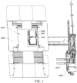
FIG. 4 is a cross-sectional view ofFIG. 3 taken along line A-A; -
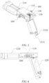
FIG. 5 is a schematic perspective view of a protective apparatus in a retracted state; -
FIG. 6 is a schematic front view of the protective apparatus in the retracted state; -
FIG. 7 is a schematic perspective view of the protective apparatus in an extended state; -
FIG. 8 is a schematic front view of the protective apparatus in the extended state; -
FIG. 9 is a schematic top view of the protective apparatus in the retracted state; -
FIG. 10 is a schematic simulated diagram of rod members of a first connecting rod and a second connecting rod of the protective apparatus in the extended state; -
FIG. 11 is a schematic diagram of the protective apparatus when transformed from a parallelogram connecting rod mechanism to a triangular connecting rod mechanism; -
FIG. 12 is a schematic simulated diagram of the first connecting rod and the second connecting rod of the protective apparatus in the retracted state; -
FIG. 13 is a schematic structural diagram of the covering member; -
FIG. 14 is a structural exploded view of a first detection apparatus in a triggered state; and -
FIG. 15 is a diagram of a second detection apparatus in a triggered state. - List of reference signs: 1000 - Battery swap device; 2000 - Battery; 2001 - Connector; 3000 - Battery swap platform; 3001 - Avoidance opening; 4000 - Battery pick-and-place device; 4001 - Fork; 100 - Movable base; 110 - Base body; 120 - Accommodating space; 130 - Third connecting rod; 131 - Limiting boss; 140 - Elastic resetting member; 200 - Protective apparatus; 210 - Drive member; 211 - Connecting member; 2121 - First connecting rod; 2122 - Second connecting rod; 2123 - First rotating shaft; 2131 - Rack; 2132 - Gear; 2133 - Sliding rail; 2134 - Slider; 220 - Covering member; 221 - Top plate; 222 - End plate; 223 - Side plate; 224 - First opening; 225 - Second opening; 300 - First detection unit; 400 - Second detection unit; α - Clockwise direction; β - Counterclockwise direction.
- Embodiments of the technical solutions of the present application will be described in more detail below with reference to the drawings. The following embodiments are merely intended to more clearly illustrate the technical solutions of the present application, so they merely serve as examples, but are not intended to limit the scope of protection of the present application.
- Unless otherwise defined, all technical and scientific terms used herein have the same meanings as those commonly understood by those skilled in the art to which the present application belongs. The terms used herein are merely for the purpose of describing specific embodiments, but are not intended to limit the present application. The terms "comprising" and "having" and any variations thereof in the description and the claims of the present application as well as the brief description of the accompanying drawings described above are intended to cover non-exclusive inclusion.
- In the description of the embodiments of the present application, the technical terms "first", "second", etc. are merely used for distinguishing different objects, and are not to be construed as indicating or implying relative importance or implicitly indicating the number, particular order or primary-secondary relationship of the technical features modified thereby. In the description of the embodiments of the present application, the phrase "a plurality of' means two or more, unless otherwise explicitly and specifically defined.
- The phrase "embodiment" mentioned herein means that the specific features, structures, or characteristics described in conjunction with the embodiment can be encompassed in at least one embodiment of the present application. The phrase at various locations in the description does not necessarily refer to the same embodiment, or an independent or alternative embodiment exclusive of another embodiment. Those skilled in the art understand explicitly or implicitly that the embodiment described herein may be combined with another embodiment.
- In the description of the embodiments of the present application, the term "and/or" is merely intended to describe the associated relationship of associated objects, indicating that three relationships can exist, for example, A and/or B can include: the three instances of A alone, A and B simultaneously, and B alone. In addition, the character "j" herein generally indicates an "or" relationship between the associated objects.
- In the description of the embodiments of the present application, the term "a plurality of" means two or more (including two), similarly the term "a plurality of groups" means two or more groups (including two groups), and the term "a plurality of pieces" means two or more pieces (including two pieces).
- In the description of the embodiments of the present application, the orientation or position relationship indicated by the technical terms "central", "longitudinal", "transverse", "length", "width", "thickness", "upper", "lower", "front"; "rear", "left", "right", "vertical", "horizontal", "top", "bottom", "inner", "outer", "clockwise", "counterclockwise", "axial", "radial", "circumferential", etc. are based on the orientation or position relationship shown in the drawings and are merely intended to facilitate and simplify the description of the embodiments of the present application, rather than indicating or implying that the apparatus or element considered must have a particular orientation or be constructed and operated in a particular orientation, and therefore not to be construed as limiting the embodiments of the present application.
- In the description of the embodiments of the present application, unless otherwise explicitly specified and defined, the technical terms "mounting", "mutual connection", "connection", "fixing", etc. should be understood in a broad sense, for example, they may be a fixed connection, a detachable connection, or an integrated connection; may be a mechanical connection or an electrical connection; and may be a direct connection or an indirect connection through an intermediate medium, and may be communication between interiors of two elements or interaction between the two elements. For those of ordinary skill in the art, the specific meaning of the above terms in the embodiments of the present application can be understood according to specific situations.
- With the development of new energy technology, there are more and more devices using a battery. When the electric energy is exhausted, a power consuming device is always connected to a charging device for replenishment with electric energy. For example, an electric vehicle can be connected to a charging pile for charging. Compared with the method of connection to a charging device, such as a charging pile, for replenishment with electric energy, the battery replacement can achieve faster replenishment with electric energy. At present, there is also a special battery swap system for battery replacement, which is provided with a battery pick-and-place device and a movable battery swap device. The battery pick-and-place device is configured to place a battery on the battery swap device, or take away the battery on the battery swap device and transfer the battery to a charging device for charging. The battery swap device carries the battery, moves between a power consuming device and the battery pick-and-place device, i.e., transfers the battery between the power consuming device and the battery pick-and-place device, and installs the battery to the power consuming device or removes the battery from the power consuming device. When the battery is installed to the power consuming device, a connector of the battery fits with a connector of the power consuming device in a plug-in manner to output electric energy to the power consuming device; and when the battery is being charged, the connector of the battery fits with a connector of the charging device in a plug-in manner to output electric energy to the battery.
- Sometimes, a short circuit occurs when the battery is connected to the power consuming device, and there is also a short circuit when the battery is connected to the charging device for charging, resulting in a safety risk. Sometimes, the battery cannot normally output or input electric energy due to poor electric connection with the power consuming device and the charging device. The inventors have found that the above situations are mostly caused by water and dust entering the connector of the battery. The inventors have noticed that the connector of the battery is usually exposed during the transfer process of the battery by the battery swap device and thus prone to dust or water ingress. Dust ingress easily leads to a poor electric connection, water ingress easily leads to a short circuit, and water ingress also makes it easier for dust to adhere to the connector and thus affects the stability of connection, resulting in reduced safety of the battery and reduced electric current transfer stability.
- In view of this, the present application provides a battery swap device, comprising a movable base and a protective apparatus. The protective apparatus is provided on the movable base and configured to protect a connector. The protective apparatus comprises a drive mechanism and a covering member. The drive mechanism is configured to drive the covering member to move to cover or uncover the connector. During the battery transfer process, the drive mechanism drives the covering member to cover the connector so as to prevent dust and water from entering the connector. After the transfer, for example, when the battery swap device and the battery reach a battery installation position of a power consuming device, the drive mechanism drives the covering member to leave the battery, so that the connector is exposed again so as to connect the connector of the battery to a current input port of the power consuming device. Thus, in the battery swap device according to the present application, during the transfer process, the covering member automatically protects the connector of the battery under the action of the drive mechanism, so as to effectively solve the problem of water and dust entering the connector, thereby improving the safety of the battery and the electric current transfer stability.
- It should be noted that a battery installation position refers to a space formed in the power consuming device for accommodating a battery, e.g., an upward recess formed in a chassis of a vehicle, the recess serves as the battery installation position for accommodating the battery, and the connector of the power consuming device is disposed in the battery installation position.
- The battery swap device and the battery swap system disclosed in the embodiments of the present application can be used for, but not limited to, replacing batteries of vehicles, and can also be used for replacing batteries of ships, aircrafts, and other power consuming devices, such as electric toys, electric tools, battery cars, electric vehicles, steamships and spacecrafts. The electric toys may include stationary or mobile toys, for example, game consoles, electric car toys, electric ship toys, electric airplane toys, etc. The electric tools may include a stationary or mobile electric tools, for example, electric machine tools, electric sweeping vehicles, etc. The spacecrafts may include airplanes, rockets, aerospace planes, spaceships, etc.
- The battery swap device and the battery swap system are described below, taking the power consuming device being a vehicle as an example.
- Referring to
FIG. 1 , the battery swap system comprises abattery swap device 1000 and a battery pick-and-place device 4000. - The battery swap system further comprises a charging device (not shown in the figure), and the charging device is configured to store a
battery 2000 and charge thebattery 2000. The battery pick-and-place device 4000 may be a robot, a stacker, etc. The battery pick-and-place device 4000 is provided with a fork 4001 (thefork 4001 may also be replaced with a mechanical arm). Using thefork 4001, an under-charge battery 2000 on thebattery swap device 1000 is removed and placed into the charging device for recycling, and a full-charge battery 2000 is taken out from the charging device and placed on thebattery swap device 1000. - The
battery swap device 1000 moves between the vehicle and the battery pick-and-place device 4000. Thebattery swap device 1000 removes the under-charge battery 2000 from the vehicle and transfers same to the battery pick-and-place device 4000. The battery pick-and-place device 4000 takes away the under-charge battery 2000 from thebattery swap device 1000 and places same into the charging device, and takes out the full-charge battery 2000 from the charging device and places same onto thebattery swap device 1000, and then thebattery swap device 1000 transfers the full-charge battery 2000 to the vehicle and installs same to the vehicle. - In the case where the power consuming device is a movable device, such as a vehicle, the battery swap system may further comprise a
battery swap platform 3000 for parking the vehicle. Thebattery swap device 1000 moves between thebattery swap platform 3000 and the battery pick-and-place device 4000. Thebattery swap platform 3000 is configured to lift the vehicle as a whole, the vehicle is located above thebattery swap platform 3000, anavoidance opening 3001 is formed in thebattery swap platform 3000, an installation position (not shown in the figure) of thebattery 2000 of the vehicle corresponds to theavoidance opening 3001, thebattery swap device 1000 is parked below theavoidance opening 3001 of the vehicle, and thebattery 2000 on thebattery swap device 1000 passes through theavoidance opening 3001 and is then installed in the installation position of thebattery 2000 of the vehicle, or thebattery 2000 in the installation position of thebattery 2000 of the vehicle is removed, passes through theavoidance opening 3001, and then falls onto thebattery swap device 1000. - As shown in
FIG. 2 , thebattery swap device 1000 comprises amovable base 100 and aprotective apparatus 200. Themovable base 100 is configured to carry thebattery 2000, and thebattery 2000 is provided with aconnector 2001 configured to transfer electric energy. Theprotective apparatus 200 is provided on themovable base 100 and configured to protect theconnector 2001. Theprotective apparatus 200 comprises a drive mechanism and a coveringmember 220. The drive mechanism is configured to drive the coveringmember 220 to move to cover or uncover theconnector 2001. - The
movable base 100 is an apparatus configured to move between the battery pick-and-place device 4000 and the vehicle, and is also an apparatus configured to carry thebattery 2000 during the transfer process. In other words, themovable base 100 moves between the battery pick-and-place device 4000 and the vehicle to transfer thebattery 2000. Themovable base 100 may be a trolley driven by a motor. The trolley moves between the battery pick-and-place device 4000 and the vehicle along a set path. A track may be provided between the battery pick-and-place device 4000 and the vehicle to set the path. The trolley is mounted to the track and moves along the track. - When the
battery 2000 is located on themovable base 100, theconnector 2001 of thebattery 2000 usually faces upwards so as to be connected to theconnector 2001 in the installation position of thebattery 2000 on a chassis of the vehicle. - The
protective apparatus 200 is an apparatus for protecting theconnector 2001 of thebattery 2000, and theprotective apparatus 200 is provided on themovable base 100. When themovable base 100 carries thebattery 2000 and moves between the battery pick-and-place device 4000 and the vehicle, theprotective apparatus 200 protects theconnector 2001 of thebattery 2000 from external dust, water and other substances. - The covering
member 220 is a component of theprotective apparatus 200 for covering theconnector 2001. The coveringmember 220 covering theconnector 2001 means that theprotective apparatus 200 at least shields an upper end surface of theconnector 2001 by means of the coveringmember 220 such that the end of theconnector 2001 to be connected to the power consuming device and the charging device is prevented from contacting with water, for example, the coveringmember 220 can protect theconnector 2001 from getting wet on a rainy day, and when there is an opening in the upper end surface of theconnector 2001, it is possible to prevent water from entering the interior of theconnector 2001 through the opening. The coveringmember 220 uncovering theconnector 2001 means that the coveringmember 220 moves away from the above of theconnector 2001, so that the power consuming device is connected to the charging device by means of theconnector 2001. - The drive mechanism is a component for providing power to the covering
member 220 so as to enable the coveringmember 220 to switch between a position where theconnector 2001 is covered and a position where theconnector 2001 is uncovered. - In the technical solution of the present application, the
protective apparatus 200 is provided on themovable base 100, the drive mechanism of theprotective apparatus 200 drives the coveringmember 220 to cover theconnector 2001 of thebattery 2000, and during the transfer process of thebattery 2000 by themovable base 100, the coveringmember 220 protects theconnector 2001 to prevent dust and water from entering theconnector 2001. After the battery is transferred in position, the drive mechanism drives the coveringmember 220 to move away from theconnector 2001 to enable thebattery 2000 to leave themovable base 100. In thebattery swap device 1000 according to the present application, during the transfer process, the coveringmember 220 automatically protects theconnector 2001 of thebattery 2000 under the action of the drive mechanism, thereby effectively improving the safety of thebattery 2000 and prolonging the service life of theconnector 2001. - As shown in
FIGS. 2, 3 and4 , in an embodiment of the present application, theprotective apparatus 200 has an extended state in which the coveringmember 220 extends out of themovable base 100 to cover theconnector 2001, and a retracted state in which the coveringmember 220 is retracted to themovable base 100. - In other words, the drive mechanism can drive the covering
member 220 to extend or retract. After thebattery 2000 is placed on themovable base 100, the drive mechanism drives the coveringmember 220 to extend to cover theconnector 2001 of thebattery 2000; and after themovable base 100 transfers thebattery 2000 in position, the drive mechanism drives the coveringmember 220 to be retracted to themovable base 100 to provide a space for thebattery 2000 to leave themovable base 100. - In the above technical solution, the drive mechanism drives the covering
member 220 to leave theconnector 2001 of thebattery 2000 and drives the coveringmember 220 to be retracted to themovable base 100, so that the wholebattery swap device 1000 takes up a small space. - The number of the
protective apparatuses 200 is not limited in the present application. In an embodiment, themovable base 100 is provided with oneprotective apparatus 200. In another embodiment, themovable base 100 is provided with twoprotective apparatuses 200, and the twoprotective apparatuses 200 may be disposed symmetrically about themovable base 100 to respectively protect the twobatteries 2000 carried on themovable base 100, or protect the twoconnectors 2001 of onebattery 2000. - As shown in
FIG. 4 , in an embodiment of the present application, themovable base 100 is provided with anaccommodating space 120. In the retracted state, the coveringmember 220 is at least partially located in theaccommodating space 120. - The
accommodating space 120 described above is a space within an outer contour of themovable base 100, and the coveringmember 220 is embedded into themovable base 100 when themovable base 100 is located within theaccommodating space 120. - In the above technical solution, when retracted, the covering
member 220 is at least partially located in theaccommodating space 120, with only part of the covering member exposed or not exposed to an outside of themovable base 100, so that thebattery swap device 1000 is of a more compact structure, has reduced space occupied by thebattery swap device 1000, and also has a function of protecting the coveringmember 220 to prevent the coveringmember 220 from being damaged by interference with foreign objects. - In an embodiment of the present application, as shown in
FIGS. 4 ,5 and 6 , in the extended state, the coveringmember 220 is located above themovable base 100; and as shown inFIGS. 4 ,7 and 8 , in the retracted state, the coveringmember 220 is located on a side surface of themovable base 100. - The
movable base 100 generally comprises a top surface, a bottom surface and a side surface. The top surface and the bottom surface are opposite in the direction of gravity, the top surface is configured to place thebattery 2000, the bottom surface is provided with walking wheels, and the side surface is located between the top surface and the bottom surface and connects the top surface to the bottom surface. In the retracted state, the coveringmember 220 is retracted to the side surface of themovable base 100 by means of the drive mechanism. In the extended state, the drive mechanism lifts the coveringmember 220 above of thebattery 2000 and covers theconnector 2001 of thebattery 2000 from above. - In the above technical solution, the covering
member 220 is retracted to the side surface of themovable base 100 and does not occupy the space above themovable base 100, so that when thebattery 2000 is placed on themovable base 100, there is no need to consider avoiding the coveringmember 220. Such a configuration will not affect the pick and place of thebattery 2000. In addition, when thebattery 2000 is mounted upwards to a power consuming device by thebattery swap device 1000, the coveringmember 220 on the side surface is less likely to interfere with the power consuming device. - In other embodiments, in the retracted state, the covering
member 220 may also be located on the top surface or the bottom surface of themovable base 100, which is not limited by the present application. - As shown in
FIG. 4 , in an embodiment of the present application, one end of the drive mechanism is mounted to themovable base 100, and the coveringmember 220 is connected to the other end of the drive mechanism. - In the above technical solution, the drive mechanism is similar to a mechanical arm, and the covering
member 220 is connected to an output end of the drive mechanism, so that the coveringmember 220 can be driven by the drive mechanism to move with multiple degrees of freedom so as to cover and uncover theconnector 2001. - As shown in
FIG. 9 , in an embodiment of the present application, the drive mechanism comprises adrive member 210, a first connectingrod 2121 and a second connectingrod 2122. One end of the first connectingrod 2121 and one end of the second connectingrod 2122 are separately hinged to themovable base 100, and the other end of the first connectingrod 2121 and the other end of the second connectingrod 2122 are separately hinged to the coveringmember 220. Thedrive member 210 is configured to drive the first connectingrod 2121 to rotate around a hinge point of the first connectingrod 2121 to themovable base 100. - In the above technical solution, the
movable base 100, the first connectingrod 2121, the coveringmember 220 and the second connectingrod 2122 are sequentially hinged. The first connectingrod 2121 is a driving member, the first connectingrod 2121 drives the coveringmember 220 and the second connectingrod 2122 to rotate, and the first connectingrod 2121 and the second connectingrod 2122 constrain the coveringmember 220, so as to guarantee the smooth movement of the coveringmember 220 and ensure the positional consistency of each covering by the coveringmember 220 to not interfere with theconnector 2001. - Further, in an embodiment of the present application, as shown in
FIGS. 4 ,7 and9 , themovable base 100 comprises abase body 110, a third connectingrod 130, and anelastic resetting member 140. The thirdconnecting rod 130 and the first connectingrod 2121 are both hinged to thebase body 110, and their hinge axes are collinear. One end of the second connectingrod 2122 is hinged to the coveringmember 220, and the other end of the second connectingrod 2122 is hinged to the third connectingrod 130. Theelastic resetting member 140 is configured to maintain the third connectingrod 130 in an initial position. - As shown in
FIG. 10 , during the movement of theprotective apparatus 200 from the extended state to the retracted state, the first connectingrod 2121, the coveringmember 220, the second connectingrod 2122 and the third connectingrod 130 firstly form a parallelogram connecting rod mechanism, and during clockwise rotation of the first connectingrod 2121, the angle of the coveringmember 220 remains unchanged, and the coveringmember 220 only translates but does not rotate. As shown inFIG. 11 , the first connectingrod 2121 drives the third connectingrod 130 to rotate clockwise against an elastic force of theelastic resetting member 140 when the first connectingrod 2121 rotates clockwise to abut against the third connectingrod 130, and at this time, the connecting rod mechanism degrades from the parallelogram connecting rod mechanism to a triangular connecting rod mechanism. As shown inFIG. 12 , the connecting rod mechanism as a whole follows the third connectingrod 130 to rotate around a hinge axis of the third connectingrod 130 and thebase body 110, and the angle of the coveringmember 220 changes. - In the embodiments of the present application, clockwise refers to a clockwise direction α shown in the figures. During the movement of the
protective apparatus 200 from the retracted state to the extended state, the first connectingrod 2121 rotates in a counterclockwise direction β, and the connecting rod mechanism is transformed from the triangular connecting rod mechanism to the parallelogram connecting rod mechanism. - Further, the third connecting
rod 130 is provided with a limitingboss 131, and when the first connectingrod 2121 rotates clockwise to abut against the limitingboss 131, the first connectingrod 2121 drives the third connectingrod 130 to rotate clockwise against the elastic force of theelastic resetting member 140, and at this time, the connecting rod mechanism degrades from the parallelogram connecting rod mechanism to the triangular connecting rod mechanism. - Further, the
elastic resetting member 140 may be a torsion spring, with one end of the torsion spring abutting against the third connectingrod 130, and the other end abutting against thebase body 110, so that the third connectingrod 130 is maintained in an initial position. - In an embodiment of the present application, the drive mechanism further comprises a first
rotating shaft 2123, one end of the first connectingrod 2121 being hinged to themovable base 100 by means of the firstrotating shaft 2123, and the firstrotating shaft 2123 being fixed to the first connectingrod 2121; and the drive mechanism further comprises agear 2132 and arack 2131 which mesh with each other, thegear 2132 being fixed to the firstrotating shaft 2123, and thedrive member 210 being configured to drive therack 2131 to move to swing the first connectingrod 2121 by means of thegear 2132. - The first
rotating shaft 2123 may be fixed to the first connectingrod 2121 by means of welding or integral forming. Thegear 2132 may be fixed to the firstrotating shaft 2123 by means of interference fitting or integral forming, therack 2131 meshes with thegear 2132, and when thedrive member 210 drives therack 2131 to move in its extension direction, therack 2131 drives thegear 2132 to rotate to swing the first connectingrod 2121 so as to move the coveringmember 220. - In the above technical solution, a linear motion is converted into rotation by means of the
gear 2132 and therack 2131 and then swings the first connectingrod 2121 to drive the coveringmember 220. The driving can be implemented with an ordinary pneumatic cylinder, electric cylinder, etc., and does not require the use of a high-torquerotary drive member 210, so as to have low requirements on thedrive member 210. - Further, the drive mechanism further comprises a connecting
member 211, and an output end of thedrive member 210 is connected to therack 2131 by means of the connectingmember 211. - In an embodiment of the present application, the drive mechanism further comprises a sliding
rail 2133 and aslider 2134 which cooperate with each other, theslider 2134 being fixedly connected to themovable base 100, and therack 2131 being fixedly connected to the slidingrail 2133. - In the above technical solution, the
slider 2134 is fixed to themovable base 100, and the slidingrail 2133 extends in an extension direction of therack 2131 and forms a sliding fit with theslider 2134, the slidingrail 2133 and theslider 2134 slide relative to each other when thedrive member 210 drives therack 2131 to move, and the slidingrail 2133 and theslider 2134 cooperate for guiding therack 2131 to move stably, ensuring a drive effect. - As shown in
FIG. 13 , in an embodiment of the present application, the coveringmember 220 is a cover-shaped member configured to cover over theconnector 2001. - The cover-shaped member described above refers to a component having an
accommodating space 120 and an opening that is in communication with theaccommodating space 120. In the above technical solution, the cover-shaped structure shields theconnector 2001 in all directions to achieve comprehensive protection and high safety. - In an embodiment of the present application, the covering
member 220 comprises atop plate 221, anend plate 222 and twoside plates 223, the twoside plates 223 being connected to opposite sides of thetop plate 221, theend plate 222 being provided at one end of thetop plate 221 and connected to thetop plate 221 and the twoside plates 223, and the side of the coveringmember 220 opposite thetop plate 221 and the side of the covering member opposite theend plate 222 being both open. - In the above technical solution, in addition to a first opening 224 opposite the
top plate 221, the cover-shaped structure further has a second opening 225 opposite theend plate 222. When the coveringmember 220 extends out of themovable base 100 to cover theconnector 2001, the side opposite theend plate 222 needs to pass over theconnector 2001 to reach the other side of theconnector 2001. Providing the opening on this side can prevent interference between the cover-shaped structure and theconnector 2001. Since there is no interference, the movement path of the coveringmember 220 can be set relatively close to themovable base 100, so that theprotective apparatus 200 requires a relatively small operating space and can thus conveniently operate in a narrow space under a vehicle. - As shown in
FIGS. 14 and15 , in an embodiment of the present application, thebattery swap device 1000 further comprises: afirst detection unit 300 configured to output a first signal when theprotective apparatus 200 is detected to be in the extended state; and/or asecond detection unit 400 configured to output a second signal when theprotective apparatus 200 is detected to be in the retracted state. - As shown in
FIG. 14 , when theprotective apparatus 200 is switched to the extended state, thefirst detection unit 300 detects that theprotective apparatus 200 extends in position and then outputs the first signal to provide, to a control system, a feedback that the coveringmember 220 covers theconnector 2001, and then the transfer of thebattery 2000 can be started. As shown inFIG. 15 , when theprotective apparatus 200 is switched to the retracted state, thesecond detection unit 400 detects that theprotective apparatus 200 is retracted in position and then outputs the second signal to provide, to the control system, a feedback that the coveringmember 220 is removed from theconnector 2001, and then thebattery 2000 can be taken away from themovable base 100. - Specifically, the
first detection unit 300 and thesecond detection unit 400 may be in-position sensors, and thefirst detection unit 300 and thesecond detection unit 400 are both mounted on thebase body 110. Thefirst detection unit 300 is configured to detect the connectingmember 211, and the connectingmember 211 triggers thefirst detection unit 300 to output the first signal when the connectingmember 211 moves to a position corresponding to the extended state of theprotective apparatus 200. Thesecond detection unit 400 is configured to detect the second connectingrod 2122, and the second connectingrod 2122 triggers thesecond detection unit 400 to output the second signal when the second connectingrod 2122 moves to a position corresponding to the retracted state of theprotective apparatus 200. - In the above technical solution, the
first detection unit 300 and thesecond detection unit 400 are provided to obtain state information of the coveringmember 220, so as to eliminate abnormality in a timely manner to ensure the safety of thebattery 2000 during the transfer process. - According to an embodiment of the present application, a battery swap system is further provided, comprising a
battery swap platform 3000, a battery pick-and-place device 4000, and abattery swap device 1000 according to the embodiments of the present application. - The
battery swap platform 3000 is configured to carry a power consuming device that has abattery 2000 to be replaced. Thebattery swap device 1000 moves between thebattery swap platform 3000 and the battery pick-and-place device 4000 to transfer thebattery 2000. The battery pick-and-place device 4000 may be a robot, a stacker, etc. The battery pick-and-place device 4000 is provided with a fork 4001 (thefork 4001 may also be replaced with a mechanical arm). Using thefork 4001, an under-charge battery 2000 on thebattery swap device 1000 is removed and placed into the charging device for recycling, and a full-charge battery 2000 is taken out from the charging device and placed on thebattery swap device 1000. - According to some embodiments of the present application, referring to
FIGS. 2-15 , the present application provides abattery swap device 1000. Thebattery swap device 1000 comprises amovable base 100 and aprotective apparatus 200. Theprotective apparatus 200 is provided on themovable base 100 and configured to protect theconnector 2001. Theprotective apparatus 200 comprises a drive mechanism and a coveringmember 220. The drive mechanism is configured to drive the coveringmember 220 to cover or uncover theconnector 2001. The drive mechanism comprises adrive member 210, a firstrotating shaft 2123, agear 2132, arack 2131, a slidingrail 2133, aslider 2134, a first connectingrod 2121 and a second connectingrod 2122. Themovable base 100 comprises abase body 110, a third connectingrod 130 and anelastic resetting member 140. One end of the first connectingrod 2121 and one end of the third connectingrod 130 are both hinged to thebase body 110 and their hinge axes are collinear, the other end of the first connectingrod 2121 is hinged to the coveringmember 220, one end of the second connectingrod 2122 is hinged to the coveringmember 220, and the other end of the second connectingrod 2122 is hinged to the third connectingrod 130. Theelastic resetting member 140 is a torsion spring, with one end of the torsion spring abutting against a fourth connecting rod, and the other end abutting against thebase body 110, so that the fourth connecting rod is maintained in an initial position. The firstrotating shaft 2123 is fixed to the first connectingrod 2121. Thegear 2132 is fixed to the firstrotating shaft 2123, and therack 2131 meshes with thegear 2132. Thedrive member 210 is a pneumatic cylinder, with an output end of the pneumatic cylinder being connected to therack 2131 by means of the connectingmember 211. Theslider 2134 is fixedly connected to thebase body 110, therack 2131 is fixedly connected to the slidingrail 2133, and theslider 2134 and theslider 2134 cooperate with each other. the coveringmember 220 comprises atop plate 221, anend plate 222 and twoside plates 223, the twoside plates 223 being connected to opposite sides of thetop plate 221, theend plate 222 being provided at one end of thetop plate 221 and connected to thetop plate 221 and the twoside plates 223, and the side of the coveringmember 220 opposite thetop plate 221 and the side of the covering member opposite theend plate 222 being both open. - The foregoing descriptions are merely preferred embodiments of the present application, but are not intended to limit the present application. For those skilled in the art, the present application may have various modifications and variations. Any modifications, equivalent substitutions, improvements, and the like made within the spirit and principle of the present application should fall within the scope of protection of the present application.
Claims (12)
- A battery swap device, comprising:a movable base configured to carry a battery that is provided with a connector configured to transfer electric energy; anda protective apparatus provided on the movable base, configured to protect the connector, and comprising a drive mechanism and a covering member, the drive mechanism being configured to drive the covering member to move to cover or uncover the connector.
- The battery swap device according to claim 1, wherein the protective apparatus has an extended state in which the covering member extends out of the movable base to cover the connector, and a retracted state in which the covering member is retracted to the movable base.
- The battery swap device according to claim 2, wherein the movable base has an accommodating space, and in the retracted state, the covering member is at least partially located in the accommodating space.
- The battery swap device according to claim 2 or 3, wherein in the retracted state, the covering member is located on a side surface of the movable base; and in the extended state, the covering member is located above the movable base.
- The battery swap device according to any one of claims 1-4, wherein one end of the drive mechanism is mounted to the movable base, and the covering member is connected to the other end of the drive mechanism.
- The battery swap device according to any one of claims 1-5, wherein the drive mechanism comprises a drive member, a first connecting rod and a second connecting rod, one end of the first connecting rod and one end of the second connecting rod being separately hinged to the movable base, the other end of the first connecting rod and the other end of the second connecting rod being separately hinged to the covering member, and the drive member being configured to drive the first connecting rod to rotate around a hinge point of the first connecting rod to the movable base.
- The battery swap device according to claim 6, wherein the drive mechanism further comprises a first rotating shaft, one end of the first connecting rod being hinged to the movable base by means of the first rotating shaft, and the first rotating shaft being fixed to the first connecting rod; and the drive mechanism further comprises a gear and a rack which mesh with each other, the gear being fixed to the first rotating shaft, and the drive member being configured to drive the rack to move so as to swing the first connecting rod by means of the gear.
- The battery swap device according to claim 7, wherein the drive mechanism further comprises a sliding rail and a slider which cooperate with each other, the slider being fixedly connected to the movable base, and the rack being fixedly connected to the sliding rail.
- The battery swap device according to any one of claims 1-8, wherein the covering member is a cover-shaped member configured to cover over the connector.
- The battery swap device according to claim 9, wherein the covering member comprises a top plate, an end plate and two side plates, the two side plates being connected to opposite sides of the top plate, the end plate being provided at one end of the top plate and connected to the top plate and the two side plates, and the side of the covering member opposite the top plate and the side of the covering member opposite the end plate being both open.
- The battery swap device according to any one of claims 2-4, further comprising:a first detection unit configured to output a first signal when the protective apparatus is detected to be in the extended state; and/ora second detection unit configured to output a second signal when the protective apparatus is detected to be in the retracted state.
- A battery swap system, comprising:a battery swap platform;a battery pick-and-place device; anda battery swap device according to any one of claims 1-11, wherein the battery swap device moves between the battery swap platform and the battery pick-and-place device to transfer a battery.
Applications Claiming Priority (2)
| Application Number | Priority Date | Filing Date | Title |
|---|---|---|---|
| CN202111166643.XA CN115912528A (en) | 2021-09-30 | 2021-09-30 | Power exchange equipment and power exchange system |
| PCT/CN2022/089981 WO2023050797A1 (en) | 2021-09-30 | 2022-04-28 | Battery replacement apparatus and battery replacement system |
Publications (2)
| Publication Number | Publication Date |
|---|---|
| EP4258510A1 true EP4258510A1 (en) | 2023-10-11 |
| EP4258510A4 EP4258510A4 (en) | 2024-08-21 |
Family
ID=85739488
Family Applications (1)
| Application Number | Title | Priority Date | Filing Date |
|---|---|---|---|
| EP22874195.5A Pending EP4258510A4 (en) | 2021-09-30 | 2022-04-28 | BATTERY REPLACEMENT DEVICE AND SYSTEM |
Country Status (6)
| Country | Link |
|---|---|
| US (1) | US20230415708A1 (en) |
| EP (1) | EP4258510A4 (en) |
| JP (1) | JP7569480B2 (en) |
| KR (1) | KR20230117211A (en) |
| CN (1) | CN115912528A (en) |
| WO (1) | WO2023050797A1 (en) |
Families Citing this family (1)
| Publication number | Priority date | Publication date | Assignee | Title |
|---|---|---|---|---|
| US20240383368A1 (en) * | 2023-05-16 | 2024-11-21 | Ample, Inc. | Battery-Exchange System and Service Station |
Family Cites Families (35)
| Publication number | Priority date | Publication date | Assignee | Title |
|---|---|---|---|---|
| US4120411A (en) * | 1977-09-15 | 1978-10-17 | Johnson Bobby L | Portable battery cart |
| US4808058A (en) * | 1987-09-29 | 1989-02-28 | Carney Wayne D | Battery handling machine |
| US5360307A (en) * | 1992-12-07 | 1994-11-01 | Windsor Industries | Battery transfer technique for vehicle |
| DE4242659A1 (en) * | 1992-12-17 | 1994-06-23 | Truetzschler Gmbh & Co Kg | Device for transporting at least one can between a sliver-delivering spinning machine, e.g. B. teasel and a fiber-fed spinning machine, for. B. route |
| US5760569A (en) * | 1997-02-26 | 1998-06-02 | Chase, Jr.; Robert B. | Replaceable battery module for electric vehicle |
| US6896468B2 (en) * | 2002-02-19 | 2005-05-24 | Tennant Company | Battery interchange system for battery powered floor maintenance equipment |
| JP3881317B2 (en) * | 2003-01-30 | 2007-02-14 | 川崎重工業株式会社 | Battery box for railway vehicles |
| US8006793B2 (en) | 2008-09-19 | 2011-08-30 | Better Place GmbH | Electric vehicle battery system |
| US20100292877A1 (en) * | 2009-05-18 | 2010-11-18 | Gabrielle W. Lee | Comprehensive engineering / operation system for electric vehicle and smart networked and decentralized power storage |
| US8858152B1 (en) * | 2010-05-06 | 2014-10-14 | Steven D. McDaniel | System for replacing batteries in electric cars |
| SE536036C2 (en) * | 2010-06-21 | 2013-04-09 | Sten Corfitsen | Procedure for replacing batteries in battery-powered vehicles. |
| AT511274B1 (en) * | 2011-04-06 | 2013-01-15 | Karl Ing Timischl | COVER LIFT FOR SECONDARY BASIN INSULATION COVERS |
| EP2718221B1 (en) * | 2011-06-07 | 2017-03-29 | Crown Equipment Corporation | Battery transfer apparatus |
| JP2013139207A (en) | 2012-01-04 | 2013-07-18 | Toyota Industries Corp | Terminal cover transition structure |
| US9358895B2 (en) * | 2013-10-28 | 2016-06-07 | Meir Avganim | Quick loading and unloading battery system for vehicles |
| KR20170102255A (en) * | 2014-12-04 | 2017-09-08 | 딕난 허버트 레이너 | Apparatus and system for providing secondary power for electric vehicles |
| US9827865B2 (en) * | 2014-12-30 | 2017-11-28 | General Electric Company | Systems and methods for recharging vehicle-mounted energy storage devices |
| NO344308B1 (en) * | 2016-06-21 | 2019-10-28 | Autostore Tech As | Storage system comprising a charging station assembly and method of replacing the power source of a remotely operated vehicle |
| CN106891865B (en) * | 2016-10-12 | 2021-07-23 | 蔚来(安徽)控股有限公司 | Chassis-type power exchange station for electric vehicle and power exchange method thereof |
| EP3326917A1 (en) * | 2016-11-24 | 2018-05-30 | Airbus Operations GmbH | A structural element, a battery set, an arrangement of a structural element and a battery set, and an aerospace vehicle |
| CN106627235B (en) | 2017-01-04 | 2020-05-15 | 上海蔚来汽车有限公司 | Full-automatic dustproof system for quick-change connector of electric automobile |
| JP6286084B1 (en) * | 2017-03-24 | 2018-02-28 | 本田技研工業株式会社 | Containment device |
| CN207070478U (en) * | 2017-07-10 | 2018-03-02 | 佛山市顺德区顺达电脑厂有限公司 | Wave-soldering autoamtic protection device for forming |
| JP6568261B2 (en) | 2017-09-29 | 2019-08-28 | 本田技研工業株式会社 | Magazine type charger |
| CN109849861A (en) * | 2017-11-30 | 2019-06-07 | 上海电巴新能源科技有限公司 | Swap station and its control method |
| CN108116378B (en) * | 2017-12-27 | 2023-08-08 | 力帆实业(集团)股份有限公司 | Electric vehicle battery replacement equipment |
| CN210041358U (en) * | 2018-03-02 | 2020-02-07 | 意法半导体有限公司 | Battery Charging Systems and Mobile Devices |
| CN208093627U (en) * | 2018-04-13 | 2018-11-13 | 蔚来汽车有限公司 | Battery transfer device |
| CN110893790B (en) * | 2018-08-22 | 2022-12-23 | 富泰华工业(深圳)有限公司 | Automatic charging and replacing system and method for electric vehicle |
| CN210554713U (en) * | 2019-10-14 | 2020-05-19 | 博众精工科技股份有限公司 | Battery electric connector waterproof device for charging and replacing station |
| CN213243581U (en) * | 2020-08-18 | 2021-05-18 | 广州视源电子科技股份有限公司 | Mobile bases, mobile devices and charging systems |
| CN213242751U (en) * | 2020-10-30 | 2021-05-18 | 徐州徐工汽车制造有限公司 | Battery connector protection device of electric automobile and electric automobile |
| CN112259874B (en) * | 2020-10-30 | 2023-11-10 | 徐州徐工汽车制造有限公司 | Battery connector protection device of electric automobile and electric automobile |
| US12030402B2 (en) * | 2020-11-09 | 2024-07-09 | Zimeno Inc. | Battery swap system |
| CN112821500B (en) * | 2021-01-27 | 2024-04-09 | 华南理工大学 | A magnetic suction automatic charging device for drones |
-
2021
- 2021-09-30 CN CN202111166643.XA patent/CN115912528A/en active Pending
-
2022
- 2022-04-28 EP EP22874195.5A patent/EP4258510A4/en active Pending
- 2022-04-28 JP JP2023541131A patent/JP7569480B2/en active Active
- 2022-04-28 KR KR1020237022886A patent/KR20230117211A/en not_active Ceased
- 2022-04-28 WO PCT/CN2022/089981 patent/WO2023050797A1/en not_active Ceased
-
2023
- 2023-09-14 US US18/467,385 patent/US20230415708A1/en active Pending
Also Published As
| Publication number | Publication date |
|---|---|
| JP2024509351A (en) | 2024-03-01 |
| US20230415708A1 (en) | 2023-12-28 |
| JP7569480B2 (en) | 2024-10-18 |
| WO2023050797A1 (en) | 2023-04-06 |
| EP4258510A4 (en) | 2024-08-21 |
| KR20230117211A (en) | 2023-08-07 |
| CN115912528A (en) | 2023-04-04 |
Similar Documents
| Publication | Publication Date | Title |
|---|---|---|
| US11634046B2 (en) | Vehicle charging system and power receiving fitting body | |
| EP4212382B1 (en) | Battery swapping platform and a battery swapping station | |
| CN216101652U (en) | Power exchange device and power exchange system | |
| KR102802824B1 (en) | Battery replacement device and battery replacement system | |
| CN113589517B (en) | Separable modularized sub-mirror structure of large space telescope and on-orbit replacement method | |
| US20170182924A1 (en) | Modular configurable automated guided vehicle | |
| US20230415708A1 (en) | Battery swap device and battery swap system | |
| US20100181129A1 (en) | Swappable modulated battery packs system for electrically driven vehicle | |
| CN118317884A (en) | Charging interface device for electric vehicles | |
| US20170182898A1 (en) | Charge head landing switch | |
| CN111873848A (en) | Power exchange station and power exchange method and device of the power exchange station | |
| CN113226846A (en) | Conveyor for moving four-wheeled vehicle | |
| CN105691229A (en) | Vehicle-mounted automatic charging mechanical arm and electric vehicle carried with same | |
| JP6308550B2 (en) | Aircraft battery with protection frame that can run on land or water and its charge exchange device | |
| CN114249013A (en) | Mobile device carrier apparatus for vehicle | |
| CN107323273B (en) | Retractable automatic charging mechanical arm and electric automobile carrying same | |
| CN217320101U (en) | Battery changing platform and battery changing station | |
| CN106274625A (en) | A kind of mechanical arm type unmanned plane hoistable platform | |
| CN119590669A (en) | A vehicle-mounted rapid take-off and landing platform device for cluster UAV formation | |
| CN219989530U (en) | A drone inspection workstation | |
| CN217347388U (en) | Flying car | |
| CN205951803U (en) | Arm -type unmanned aerial vehicle lift platform of machinery | |
| CN222876060U (en) | A turnover vehicle for transporting wiring harness materials | |
| CN116573093B (en) | Folding transport vehicle and vehicle | |
| KR102936474B1 (en) | Charging apparatus for moving robot |
Legal Events
| Date | Code | Title | Description |
|---|---|---|---|
| STAA | Information on the status of an ep patent application or granted ep patent |
Free format text: STATUS: THE INTERNATIONAL PUBLICATION HAS BEEN MADE |
|
| PUAI | Public reference made under article 153(3) epc to a published international application that has entered the european phase |
Free format text: ORIGINAL CODE: 0009012 |
|
| STAA | Information on the status of an ep patent application or granted ep patent |
Free format text: STATUS: REQUEST FOR EXAMINATION WAS MADE |
|
| 17P | Request for examination filed |
Effective date: 20230704 |
|
| AK | Designated contracting states |
Kind code of ref document: A1 Designated state(s): AL AT BE BG CH CY CZ DE DK EE ES FI FR GB GR HR HU IE IS IT LI LT LU LV MC MK MT NL NO PL PT RO RS SE SI SK SM TR |
|
| A4 | Supplementary search report drawn up and despatched |
Effective date: 20240719 |
|
| RIC1 | Information provided on ipc code assigned before grant |
Ipc: H02J 7/00 20060101AFI20240715BHEP |
|
| RAP1 | Party data changed (applicant data changed or rights of an application transferred) |
Owner name: CONTEMPORARY AMPEREX TECHNOLOGY(HONG KONG) LIMITED |
|
| DAV | Request for validation of the european patent (deleted) | ||
| DAX | Request for extension of the european patent (deleted) |