EP4258475A1 - Method and system for managing orientation direction of mobile communication base station antenna - Google Patents
Method and system for managing orientation direction of mobile communication base station antenna Download PDFInfo
- Publication number
- EP4258475A1 EP4258475A1 EP21901088.1A EP21901088A EP4258475A1 EP 4258475 A1 EP4258475 A1 EP 4258475A1 EP 21901088 A EP21901088 A EP 21901088A EP 4258475 A1 EP4258475 A1 EP 4258475A1
- Authority
- EP
- European Patent Office
- Prior art keywords
- antenna
- antenna device
- spatial orientation
- orientation information
- video data
- Prior art date
- Legal status (The legal status is an assumption and is not a legal conclusion. Google has not performed a legal analysis and makes no representation as to the accuracy of the status listed.)
- Pending
Links
Images




Classifications
-
- H—ELECTRICITY
- H01—ELECTRIC ELEMENTS
- H01Q—ANTENNAS, i.e. RADIO AERIALS
- H01Q3/00—Arrangements for changing or varying the orientation or the shape of the directional pattern of the waves radiated from an antenna or antenna system
- H01Q3/26—Arrangements for changing or varying the orientation or the shape of the directional pattern of the waves radiated from an antenna or antenna system varying the relative phase or relative amplitude of energisation between two or more active radiating elements; varying the distribution of energy across a radiating aperture
- H01Q3/2605—Array of radiating elements provided with a feedback control over the element weights, e.g. adaptive arrays
-
- H—ELECTRICITY
- H01—ELECTRIC ELEMENTS
- H01Q—ANTENNAS, i.e. RADIO AERIALS
- H01Q1/00—Details of, or arrangements associated with, antennas
- H01Q1/12—Supports; Mounting means
- H01Q1/125—Means for positioning
-
- H—ELECTRICITY
- H01—ELECTRIC ELEMENTS
- H01Q—ANTENNAS, i.e. RADIO AERIALS
- H01Q1/00—Details of, or arrangements associated with, antennas
- H01Q1/12—Supports; Mounting means
- H01Q1/22—Supports; Mounting means by structural association with other equipment or articles
- H01Q1/24—Supports; Mounting means by structural association with other equipment or articles with receiving set
- H01Q1/241—Supports; Mounting means by structural association with other equipment or articles with receiving set used in mobile communications, e.g. GSM
- H01Q1/246—Supports; Mounting means by structural association with other equipment or articles with receiving set used in mobile communications, e.g. GSM specially adapted for base stations
-
- H—ELECTRICITY
- H01—ELECTRIC ELEMENTS
- H01Q—ANTENNAS, i.e. RADIO AERIALS
- H01Q3/00—Arrangements for changing or varying the orientation or the shape of the directional pattern of the waves radiated from an antenna or antenna system
- H01Q3/005—Arrangements for changing or varying the orientation or the shape of the directional pattern of the waves radiated from an antenna or antenna system using remotely controlled antenna positioning or scanning
-
- H—ELECTRICITY
- H01—ELECTRIC ELEMENTS
- H01Q—ANTENNAS, i.e. RADIO AERIALS
- H01Q3/00—Arrangements for changing or varying the orientation or the shape of the directional pattern of the waves radiated from an antenna or antenna system
- H01Q3/02—Arrangements for changing or varying the orientation or the shape of the directional pattern of the waves radiated from an antenna or antenna system using mechanical movement of antenna or antenna system as a whole
- H01Q3/08—Arrangements for changing or varying the orientation or the shape of the directional pattern of the waves radiated from an antenna or antenna system using mechanical movement of antenna or antenna system as a whole for varying two co-ordinates of the orientation
Definitions
- the present disclosure relates to an antenna, and more particularly, to a method and system for managing the orientation direction of a mobile communication base station antenna capable of monitoring and adjusting information on the orientation direction of the antenna.
- a position and angle of an antenna installed in a mobile communication base station should be determined according to precise design.
- the installation location of the antenna is determined according to the result of network design considering coverage and traffic.
- An orientation angle of the antenna is determined by considering a sector orientation angle of a horizontal component of a beam.
- a tilting angle of the antenna is determined by considering a tilting angle of a vertical component of the beam. The orientation angle and tilting angle are optimized to suit a radio environment of a site where the antenna is installed through testing.
- Radio signals in a frequency band of 5G 3.5 GHz have strong radio wave straightness. Therefore, in order to secure a planned service coverage, the antenna should be installed with a pre-designed antenna azimuth. In the future, even when increasing antennas, design and optimization should be performed based on consistent indicators to secure service quality. In particular, since the radio wave straightness increases as the frequency band increases, a design that minimizes azimuth errors should be performed in antenna installation.
- a tilting angle and an orientation angle of a pre-installed antenna need to be readjusted.
- a tilt of a mast supporting the antenna may change due to an external environment such as strong wind.
- a clamp for combining the antenna and the mast may be twisted in a horizontal direction.
- a main object thereof is to provide an antenna management method and system for measuring the orientation direction of a mobile communication base station antenna in real time and controlling an antenna so that the antenna has a target orientation direction.
- an antenna management system including a direction control device for controlling the orientation direction of a mobile communication base station antenna, wherein the direction control device comprises: a data receiving unit configured to receive spatial orientation information of an antenna device or video data obtained by capturing a foreground orientated by the antenna device from a measuring device; and a control unit configured to control a tilting and steering means of the antenna device so that the antenna device has a preset target spatial orientation using at least one of the spatial orientation information and the video data.
- an antenna management method performed by a direction control device for controlling an orientation direction of a mobile communication base station antenna on an antenna management system including the direction control device, the antenna management method comprising: receiving spatial orientation information of an antenna device or video data obtained by capturing a foreground orientated by the antenna device from a measuring device; and controlling a tilting and steering means of the antenna device so that the antenna device has a preset target spatial orientation using at least one of the spatial orientation information and the video data.
- an antenna management system including a measuring device for measuring an orientation direction of a mobile communication base station antenna, wherein the measuring device mounted on a housing of an antenna device comprises: a communication unit configured to transmit or receive data to or from a direction control device for controlling a tilting and steering means of the antenna device or the antenna device; a direction measuring unit configured to detect an incident angle of sunlight to measure spatial orientation information of the antenna device; and an image generating unit configured to generate video data obtained by capturing a foreground orientated by the antenna device.
- a spatial direction of an antenna is measured and controlled using a measuring device and a direction control device, it is possible to maintain base station facilities without putting workers into the field.
- the present disclosure relates to measuring 3D spatial orientation information of an antenna device in real time, and remotely monitoring and controlling a direction of the antenna device based on spatial orientation information.
- the present disclosure uses a low-cost and low error rate measuring device compared to an expensive measuring instrument of a Dual GPS method. Since the measuring device of the present disclosure has a small size compared to the size of the antenna, there is an advantage in that it is easy to install on the antenna. Since the measuring device measures the 3D spatial orientation information of the antenna device, it may be referred to as a beam navigator (BN).
- BN beam navigator
- FIG. 1 is a conceptual diagram for describing an antenna management system according to one embodiment of the present disclosure.
- An antenna management system 10 includes any one of a measuring device 100 and a direction control device 102.
- the measuring device 100 is a device that measures spatial orientation information of an antenna device 104 by detecting an incident angle of sunlight.
- the measuring device 100 may be mounted on a housing of the antenna device 104 and generates video data obtained by capturing the foreground orientated by the antenna device 104.
- the measured spatial orientation information and captured video data will be described later with reference to FIG. 3 .
- the direction control device 102 is a device for controlling a tilting and steering means provided in the antenna device 104 so that the antenna device 104 has a target spatial orientation.
- the tilting and steering means may be implemented by a mast supporting the antenna device 104 and a clamping device connecting the antenna device 104.
- the direction control device 102 includes a data receiving unit (not shown) that receives the spatial orientation information of the antenna device 104 or video data obtained by capturing the foreground orientated by the antenna device 104 from the measuring device, and a control unit (not shown) that controls the tilting and steering means of the antenna device 104 so that the antenna device 104 has a preset target spatial orientation using at least one of the spatial orientation information and the video data.
- the direction control device 102 uses at least one of the spatial orientation information and video data measured by the measuring device 100 to measure an error between a current orientation direction of the antenna device 104 and the target spatial orientation.
- the direction control device 102 may be implemented by a control circuit included in the antenna device 104.
- the direction control device 102 may be implemented by part of a remote administrator (RAD) that manages the antenna device 104 installed in a plurality of sites.
- the direction control device 102 may be implemented by a portable controller (RPC: RTS Portable Controller, hereinafter, referred to as "RPC" for RTS control carried by a base station operator.
- RPC RTS Portable Controller
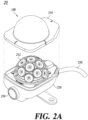
- FIG. 2 is an exemplary diagram for describing hardware of the measuring device according to one embodiment of the present disclosure.
- FIG. 2a an exploded perspective view 20 in which only some components of the measuring device 100 are separated is shown.
- the housing of the measuring device 100 includes a protection cap 210, a body 220, and a camera cover 230.
- FIG. 2a showing the protection cap 210, the body 220, and the camera cover is an exemplary drawing for describing the appearance of the measuring device 100, and the specific appearance of the measuring device 100 may be varied in various ways according to the embodiment of the present disclosure.
- a cross-sectional side view 22 of the metering device 100 is shown.
- the inside of the measuring device 100 includes at least a photo sensor 212, a main board 222, a surge board 224, a control cable 226, and a camera module 232.
- the measuring device 100 may further include a GPS module (not shown) that provides GPS information of the antenna device 104 corresponding to the installation location of the measuring device 100.
- a plurality of photo sensors 212 which are arranged with different orientation directions from each other on the spherical surface of a structure having a half-sphere shape surrounded by the protection cap 210, measure the amount of light of sunlight.
- Each photo sensor 212 is disposed at intervals of a predetermined angle in a vertical direction in order to detect an incident angle of sunlight.
- Each photo sensor 212 is arranged at intervals of a predetermined angle in a horizontal direction in order to determine the orientation of the antenna device 104.
- the measuring device 100 can measure the 3D spatial orientation information having azimuth, tilt, and roll as elements.
- the main board 222 processes data collected by each module included in the measuring device 100 and controls each module.
- the surge board 224 prevents malfunctions and defects of the measuring device 100 due to overvoltage.
- the camera module 232 captures the foreground orientated by the antenna device 104 in which the measuring device 100 is installed.
- the GPS module can measure the latitude and longitude of the current location where the beam navigator is installed.
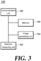
- FIG. 3 is a block configuration diagram for describing the measuring device according to one embodiment of the present disclosure.
- the measuring device 100 includes all or some of a communication unit 300, a direction measuring unit 302, an image generating unit 304, and a memory 306.
- the measuring device 20 shown in FIG. 3 is according to one embodiment of the present disclosure, and all blocks shown in FIG. 3 are not essential components, and some blocks included in the measuring device 100 in another embodiment may be added, changed, or deleted.
- the direction measuring unit 302 and the image generating unit 304 may be logical components implemented by a processor included in the main board 222.
- the communication unit 300 provides access to an external network.
- a remote administrator 400 may transmit or receive data to or from the direction control device 102 or the antenna device 104 through the communication unit 300.
- the control cable 226 may operate as a part of communication unit 300.
- the measuring device 100 transmits and receives measurement data and control data to or from an external device through the control cable 226.
- the direction measuring unit 302 calculates the incident angle of sunlight based on output information measured by the plurality of photo sensors 212.
- the direction measuring unit 302 calculates the azimuth of the antenna device 104 based on the calculated incident angle of sunlight, single GPS information collected by the GPS module, and a date and time of measuring the amount of sunlight.
- the azimuth calculated by the direction measuring unit 302 may be an absolute azimuth or absolute horizontal azimuth.
- the single GPS information includes the latitude and longitude of the location where the measuring device 100 is installed.
- the direction measuring unit 302 may measure the tilt and roll of the antenna device 104 in real time using an Inertial Measurement Unit sensor (IMU sensor). Meanwhile, a method for measuring the azimuth, tilt, and roll using the GPS device and sensor is disclosed in Korean Patent Publication No. 2018-0023198 or the like.
- IMU sensor Inertial Measurement Unit sensor
- the direction measuring unit 302 tracks a change in position of the antenna device 104 by using a motion sensor to measure the azimuth of the antenna device 104 in a meteorological environment in which sunlight cannot be detected.
- the motion sensor may be a displacement sensor that detects the amount of change in position, but the specific type of motion sensor is not limited.
- the direction measuring unit 302 may output the 3D spatial orientation information having calculated and measured azimuth, tilt, and roll as respective elements.
- the direction measuring unit 302 may be implemented by a photo sensor module including a plurality of photo sensors 212 and part of the main board 222.
- Exemplary measurement data output by the direction measuring unit 302 is shown in Table 1.
- the measurement data includes the latitude and longitude.
- a tolerance means a difference between the latitude and longitude provided by Google Map and the measurement data by the direction measuring unit 302. [Table 1] Item Measure AVG.
- Table 2 shows exemplary azimuth data measured by the direction measuring unit 302 in an actual mobile communication base station field.
- an error represents a difference between the azimuth provided by Google Maps and the azimuth measured by the direction measuring unit 302.
- the image generating unit 304 generates the image or video data obtained by capturing the foreground orientated by the antenna device 104 in which the measuring device 100 is installed.
- the direction control device 102 monitors a change in the orientation direction of the antenna device 104 using video data generated by the image generating unit 304.
- the image generating unit 304 may be implemented by the camera module 232 and part of the main board 222.
- the memory 306 may store a program that causes a processor to perform a method of controlling the orientation direction of the mobile communication base station antenna according to one embodiment of the present disclosure.
- the program may include a plurality of instructions executable by the processor, and a positioning database update method may be performed by executing the plurality of instructions by the processor.
- the memory 306 may include at least one of volatile memory and non-volatile memory.
- the volatile memory includes static random access memory (SRAM) or dynamic random access memory (DRAM), and the like, and the non-volatile memory includes flash memory and the like.
- FIG. 4 is an exemplary diagram for describing one embodiment in which the direction control device controls the antenna based on communication with the RPC according to one embodiment of the present disclosure.
- antenna 104 is supported by a mast 404, and the direction control device 102 may be disposed between the antenna 104 and the mast 404.
- the direction control device 102 may be implemented as part of an antenna to control a clamping device supporting the antenna 104.
- the measuring device 100 measures the 3D spatial orientation information of the antenna device 104 measured in real time.
- the direction control device 102 controls a remote tilting and steering means (hereinafter, "RTS module") provided in the antenna device 104 based on the spatial orientation information. Specifically, the direction control device 102 remotely monitors the tilt and steering of the antenna device 104 and aligns the antenna device 104 so that the antenna device 140 has the target spatial orientation.
- RTS module remote tilting and steering means
- a clamping device for an antenna and a control method thereof to change the angle of the antenna device 104 are known in the art, and thus, a detailed description thereof will be omitted.
- the RPC 402 receives current spatial orientation information of the plurality of antenna devices 104 measured by the measuring device 100.
- the direction control device 102 for controlling the tilting angle and orientation angle of the antenna device 104 may be implemented by the RAD 400 or the RPC 402.
- the RPC 402 may transmit or receive data with the measuring device 100 using wired or wireless communication.
- the RPC 402 may be connected wirelessly or in a wired manner with an RTS module for providing the RTS function.
- the RPC 402 may perform wired communication using a local area network (LAN) or a wide area network (WAN).
- RPC 402 may perform wireless communication through a cellular network or a Wi-Fi network.
- the specific type of wireless or wired communication network used by the RPC 402 is not limited thereto.
- the base station operator may use the RPC 402 at the installation or maintenance site of the antenna device 104 to check the received spatial orientation information, and thus, check whether the current orientation direction of each antenna device 104 matches the originally designed target spatial orientation.
- the RPC 402 may generate control data for each antenna device 104 to have a target spatial orientation based on the current spatial orientation information of the plurality of antenna devices 104.
- the RPC 402 may control the tilting angle and orientation angle of the antenna device 104 by transmitting control data to the RTS module of the antenna device 104.
- the RPC 402, the measuring device 100, and the RTS module may transmit or receive measurement data and control data to each other according to an Antenna Interface Standards Group protocol (AISG protocol).
- AISG protocol is a standardized specification to secure interconnectivity for the antenna control method, and since it is already known in the art, a detailed description thereof will be omitted.
- FIG. 5 is an exemplary view for describing one embodiment of monitoring the antenna device using the video data generated by the measuring device according to one embodiment of the present disclosure.
- the remote administrator 400 disposed in a central control center receives, through the AISG protocol", the spatial orientation information and the video data generated by the measuring device 100 from the antenna devices 104 installed in a plurality of places.
- a manager of the central control center can monitor the foreground orientated by the antenna device 104 located in each base station using video data provided through a display 500. In addition, the manager can monitor the GPS coordinates and spatial orientation coordinates of each antenna device 104.
- an operation & management center 502 receives information generated by the measuring device 100 disposed on the antenna device 104 installed in a plurality of sites.
- the information generated by the measuring device 100 includes the azimuth, the tilt, the roll, the video data obtained by capturing the foreground to which the antenna device 104 is directed, and the GPS information.
- the GPS information includes the latitude, longitude, and altitude of the antenna device 104.
- the information generated by the measuring device 100 is transmitted to a core network 508 through an AISG protocol via an optical fiber 504 and a digital unit (DU) 506.
- the operation & management center 502 connected to the core network 508 is a communication network management system and can monitor the change in the orientation direction of the antenna device 104 in real time.
- FIG. 6 is an exemplary diagram for describing one embodiment in which the measuring device transmits the video data to the remote administrator according to one embodiment of the present disclosure.
- the remote administrator 400 receives the current spatial orientation information of the antenna device 104 using wired or wireless communication.
- the direction control device 102 for controlling the tilting angle and orientation angle of the antenna device 104 may be implemented by the remote administrator 400.
- the remote administrator 400 may control the RTS module of the antenna device 104 based on the difference between the current spatial orientation information and the target spatial orientationspatial orientation information. That is, the remote administrator 400 may detect a change in the orientation direction of the antenna device 104 due to an external environment in real time and automatically control the RTS module so that the antenna device 104 has the target orientation direction.
- the remote administrator 400 may monitor and control the change in orientation direction of the antenna device 104 without the spatial orientation information of the antenna device 104.
- an exceptional situation in which the measuring device 100 cannot measure spatial orientation information of the antenna device 104 may be assumed.
- the exceptional situation may be a situation in which sunlight is not incident at night, bad weather in which the amount of sunlight is insignificant, or a case where a failure of the photo sensor 212 occurs.
- the remote administrator 400 uses the video data, which is generated by the measuring device 100, in an auxiliary way when orientation direction monitoring based on the spatial orientation information of the antenna device 104 is impossible.
- the remote administrator 400 may monitor the change in the orientation direction of the antenna device 104 based on the video data, and control the tilting angle and orientation angle of the antenna device 104.
- the remote administrator 400 may store an image frame of video data captured in a situation in which the spatial orientation information of the antenna device 104 measured by the measuring device 100 coincides with target spatial orientationspatial orientation information as a reference image. Subsequently, when measurement of the spatial orientation information by the measuring device 100 is impossible, the remote administrator 400 compares the image frame obtained from the video stream obtained by capturing the foreground to which the antenna device 104 is directed with the reference image. Specifically, the remote administrator 400 detects the change in the orientation direction by controlling the RTS module of the antenna device 104 so that the center of an image frame received in real time coincides with the center of the reference image.
- the remote administrator 400 may remotely adjust the tilting angle and orientation angle of the antenna device 104 in response to changes in the wireless environment on the path through which radio waves are transmitted from the base station antenna device 104.
- the change in the wireless environment means a change in the wireless communication environment due to new building construction, land development, or terrain change.
- the remote administrator 400 may provide the spatial orientation information measured by the measuring device 100 to a baseband unit (BBU).
- BBU baseband unit
- Spatial orientation information which is accurate information about the actual antenna beam direction, can be used in a solution for network optimization.
- a mobile communication service provider checks the antenna beam direction through the spatial orientation information measured by the measuring device 100 according to the present disclosure. The mobile communication service provider can build a more precise network optimization solution by remotely aligning the desired antenna beam direction using the RTS module.
- the direction control device 102 may be implemented by a control circuit of antenna device 104.
- the control circuit receives the current spatial orientation information of the antenna device 104 from the measuring device 100.
- An algorithm for automatically controlling the RTS module of the antenna device 104 based on the difference between the current spatial orientation information and the target spatial orientationspatial orientation information may be mounted in the control circuit. That is, the control circuit of the antenna device 104 may detect the change in the orientation direction of the antenna device 104 due to external factors in real time and provide a function of automatically restoring the antenna device 104 to have the target orientation direction.
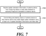
- FIG. 7 is a flow chart for describing each process included in the antenna management method performed by the direction control device according to one embodiment of the present disclosure.
- the data receiving unit included in the direction control device 102 receives the spatial orientation information of the antenna device 104 from the measuring device 100 or the video data obtained by capturing the foreground orientated by the antenna device 104 (S700).
- the control unit included in the direction control device 102 controls the tilting and steering means of the antenna device 104 so that the antenna device 104 has the preset target spatial orientation using at least one of the spatial orientation information and the video data (S702).
- Various implementations of the devices and methods described herein may include a digital electronic circuit, an integrated circuit, a field programmable gate arrays (FPGA), an application specific integrated circuit (ASIC), computer hardware, firmware, software, and/or combinations thereof. These various implementations may include being implemented by one or more computer programs executable on a programmable system.
- the programmable system includes at least one programmable processor (which may be a special purpose processor or may be a general-purpose processor) coupled to receive data and instructions from and transmit data and instructions to the storage system, at least one input device, and at least one output device.
- Computer programs also known as programs, software, software applications, or code
- the computer-readable recording medium includes all types of recording devices in which data that can be read by a computer system is stored.
- the computer-readable recording medium may further include non-volatile or non-transitory media such as a ROM, a CD-ROM, a magnetic tape, a floppy disk, a memory card, a hard disk, a magneto-optical disk, and a storage device or a transitory medium such as a data transmission medium.
- the computer-readable recording medium may be distributed in computer systems connected through a network, and computer-readable codes may be stored and executed in a distributed manner.
- the computer includes a programmable processor, a data storage system (including volatile memory, non-volatile memory, or other types of storage systems, or combinations thereof) and at least one communication interface.
- the programmable computer may be one of a server, a network device, a set top box, an embedded device, a computer expansion module, a personal computer, a laptop, a personal data assistant (PDA), a cloud computing system, and a mobile device.
- PDA personal data assistant
Landscapes
- Engineering & Computer Science (AREA)
- Computer Networks & Wireless Communication (AREA)
- Mobile Radio Communication Systems (AREA)
Abstract
Description
- The present disclosure relates to an antenna, and more particularly, to a method and system for managing the orientation direction of a mobile communication base station antenna capable of monitoring and adjusting information on the orientation direction of the antenna.
- Contents described below merely provide background information related to embodiments of the present disclosure and do not constitute the related art.
- A position and angle of an antenna installed in a mobile communication base station should be determined according to precise design. In general, the installation location of the antenna is determined according to the result of network design considering coverage and traffic. An orientation angle of the antenna is determined by considering a sector orientation angle of a horizontal component of a beam. A tilting angle of the antenna is determined by considering a tilting angle of a vertical component of the beam. The orientation angle and tilting angle are optimized to suit a radio environment of a site where the antenna is installed through testing.
- Radio signals in a frequency band of 5G 3.5 GHz have strong radio wave straightness. Therefore, in order to secure a planned service coverage, the antenna should be installed with a pre-designed antenna azimuth. In the future, even when increasing antennas, design and optimization should be performed based on consistent indicators to secure service quality. In particular, since the radio wave straightness increases as the frequency band increases, a design that minimizes azimuth errors should be performed in antenna installation.
- In response to changes in a wireless environment, there are cases in which a tilting angle and an orientation angle of a pre-installed antenna need to be readjusted. For example, a tilt of a mast supporting the antenna may change due to an external environment such as strong wind. Alternatively, a clamp for combining the antenna and the mast may be twisted in a horizontal direction. When the tilting angle or orientation angle of the antenna is different, there is a problem in that a worker should perform direction measurement and alignment work using an expensive measuring instrument of a Dual GPS method in the field.
- Therefore, it is necessary to measure spatial orientation information of an antenna without putting a worker in a field of a mobile communication base station, and to adjust a tilting angle and an orientation angle of the antenna so that the antenna has a target spatial orientation.
- According to one aspect of the present disclosure, a main object thereof is to provide an antenna management method and system for measuring the orientation direction of a mobile communication base station antenna in real time and controlling an antenna so that the antenna has a target orientation direction.
- According to an embodiment of the present disclosure, an antenna management system including a direction control device for controlling the orientation direction of a mobile communication base station antenna, wherein the direction control device comprises: a data receiving unit configured to receive spatial orientation information of an antenna device or video data obtained by capturing a foreground orientated by the antenna device from a measuring device; and a control unit configured to control a tilting and steering means of the antenna device so that the antenna device has a preset target spatial orientation using at least one of the spatial orientation information and the video data.
- According to another embodiment of the present disclosure, an antenna management method performed by a direction control device for controlling an orientation direction of a mobile communication base station antenna on an antenna management system including the direction control device, the antenna management method comprising: receiving spatial orientation information of an antenna device or video data obtained by capturing a foreground orientated by the antenna device from a measuring device; and controlling a tilting and steering means of the antenna device so that the antenna device has a preset target spatial orientation using at least one of the spatial orientation information and the video data.
- According to yet another embodiment of the present disclosure, an antenna management system including a measuring device for measuring an orientation direction of a mobile communication base station antenna, wherein the measuring device mounted on a housing of an antenna device comprises: a communication unit configured to transmit or receive data to or from a direction control device for controlling a tilting and steering means of the antenna device or the antenna device; a direction measuring unit configured to detect an incident angle of sunlight to measure spatial orientation information of the antenna device; and an image generating unit configured to generate video data obtained by capturing a foreground orientated by the antenna device.
- According to an embodiment of the present disclosure, since a spatial direction of an antenna is measured and controlled using a measuring device and a direction control device, it is possible to maintain base station facilities without putting workers into the field.
-
-
FIG. 1 is a conceptual diagram for describing an antenna management system according to one embodiment of the present disclosure. -
FIG. 2 is an exemplary diagram for describing hardware of a measuring device according to one embodiment of the present disclosure. -
FIG. 3 is a block configuration diagram for describing the measuring device according to one embodiment of the present disclosure. -
FIG. 4 is an exemplary diagram for describing one embodiment in which a direction control device controls an antenna based on communication with an RPC according to one embodiment of the present disclosure. -
FIG. 5 is an exemplary view for describing one embodiment of monitoring an antenna device using video data generated by a measuring device according to one embodiment of the present disclosure. -
FIG. 6 is an exemplary diagram for describing one embodiment in which the measuring device transmits the video data to a remote administrator according to one embodiment of the present disclosure. -
FIG. 7 is a flow chart for describing each process included in an antenna management method performed by a direction control device according to one embodiment of the present disclosure. - The present disclosure relates to measuring 3D spatial orientation information of an antenna device in real time, and remotely monitoring and controlling a direction of the antenna device based on spatial orientation information. In order to measure the 3D spatial orientation information of the antenna device, the present disclosure uses a low-cost and low error rate measuring device compared to an expensive measuring instrument of a Dual GPS method. Since the measuring device of the present disclosure has a small size compared to the size of the antenna, there is an advantage in that it is easy to install on the antenna. Since the measuring device measures the 3D spatial orientation information of the antenna device, it may be referred to as a beam navigator (BN).
- The detailed description set forth below in conjunction with the accompanying drawings is intended to describe exemplary embodiments of the present disclosure, and is not intended to represent the only embodiments in which the present disclosure may be practiced.
-
FIG. 1 is a conceptual diagram for describing an antenna management system according to one embodiment of the present disclosure. - An
antenna management system 10 according to one embodiment of the present disclosure includes any one of ameasuring device 100 and adirection control device 102. - The
measuring device 100 is a device that measures spatial orientation information of anantenna device 104 by detecting an incident angle of sunlight. Themeasuring device 100 may be mounted on a housing of theantenna device 104 and generates video data obtained by capturing the foreground orientated by theantenna device 104. The measured spatial orientation information and captured video data will be described later with reference toFIG. 3 . - The
direction control device 102 is a device for controlling a tilting and steering means provided in theantenna device 104 so that theantenna device 104 has a target spatial orientation. In one embodiment, the tilting and steering means may be implemented by a mast supporting theantenna device 104 and a clamping device connecting theantenna device 104. For example, thedirection control device 102 includes a data receiving unit (not shown) that receives the spatial orientation information of theantenna device 104 or video data obtained by capturing the foreground orientated by theantenna device 104 from the measuring device, and a control unit (not shown) that controls the tilting and steering means of theantenna device 104 so that theantenna device 104 has a preset target spatial orientation using at least one of the spatial orientation information and the video data. Thedirection control device 102 uses at least one of the spatial orientation information and video data measured by themeasuring device 100 to measure an error between a current orientation direction of theantenna device 104 and the target spatial orientation. In one embodiment, thedirection control device 102 may be implemented by a control circuit included in theantenna device 104. In another embodiment, thedirection control device 102 may be implemented by part of a remote administrator (RAD) that manages theantenna device 104 installed in a plurality of sites. In another embodiment, thedirection control device 102 may be implemented by a portable controller (RPC: RTS Portable Controller, hereinafter, referred to as "RPC") for RTS control carried by a base station operator. One embodiment of operations of the RAD and RPC will be described later with reference toFIGS. 4 and6 . -
FIG. 2 is an exemplary diagram for describing hardware of the measuring device according to one embodiment of the present disclosure. - Referring to
FIG. 2a , an exploded perspective view 20 in which only some components of themeasuring device 100 are separated is shown. The housing of themeasuring device 100 includes aprotection cap 210, abody 220, and acamera cover 230.FIG. 2a showing theprotection cap 210, thebody 220, and the camera cover is an exemplary drawing for describing the appearance of themeasuring device 100, and the specific appearance of themeasuring device 100 may be varied in various ways according to the embodiment of the present disclosure. - Referring to
FIG. 2b , across-sectional side view 22 of themetering device 100 is shown. The inside of themeasuring device 100 includes at least aphoto sensor 212, amain board 222, asurge board 224, acontrol cable 226, and acamera module 232. In one embodiment, themeasuring device 100 may further include a GPS module (not shown) that provides GPS information of theantenna device 104 corresponding to the installation location of themeasuring device 100. - Referring to
FIG. 2a , a plurality ofphoto sensors 212, which are arranged with different orientation directions from each other on the spherical surface of a structure having a half-sphere shape surrounded by theprotection cap 210, measure the amount of light of sunlight. Eachphoto sensor 212 is disposed at intervals of a predetermined angle in a vertical direction in order to detect an incident angle of sunlight. Eachphoto sensor 212 is arranged at intervals of a predetermined angle in a horizontal direction in order to determine the orientation of theantenna device 104. As shown inFIG. 2a , since the plurality ofphoto sensors 212 are disposed on the spherical surface of the hemispherical structure, the measuringdevice 100 can measure the 3D spatial orientation information having azimuth, tilt, and roll as elements. - The
main board 222 processes data collected by each module included in themeasuring device 100 and controls each module. Thesurge board 224 prevents malfunctions and defects of the measuringdevice 100 due to overvoltage. Thecamera module 232 captures the foreground orientated by theantenna device 104 in which themeasuring device 100 is installed. The GPS module can measure the latitude and longitude of the current location where the beam navigator is installed. -
FIG. 3 is a block configuration diagram for describing the measuring device according to one embodiment of the present disclosure. - The measuring
device 100 according to one embodiment of the present disclosure includes all or some of acommunication unit 300, adirection measuring unit 302, animage generating unit 304, and amemory 306. The measuringdevice 20 shown inFIG. 3 is according to one embodiment of the present disclosure, and all blocks shown inFIG. 3 are not essential components, and some blocks included in themeasuring device 100 in another embodiment may be added, changed, or deleted. Thedirection measuring unit 302 and theimage generating unit 304 may be logical components implemented by a processor included in themain board 222. - Hereinafter, each component included in the
measuring device 100 will be described with reference toFIG. 3 . - The
communication unit 300 provides access to an external network. For example, aremote administrator 400 may transmit or receive data to or from thedirection control device 102 or theantenna device 104 through thecommunication unit 300. In one embodiment, thecontrol cable 226 may operate as a part ofcommunication unit 300. The measuringdevice 100 transmits and receives measurement data and control data to or from an external device through thecontrol cable 226. - The
direction measuring unit 302 calculates the incident angle of sunlight based on output information measured by the plurality ofphoto sensors 212. Thedirection measuring unit 302 calculates the azimuth of theantenna device 104 based on the calculated incident angle of sunlight, single GPS information collected by the GPS module, and a date and time of measuring the amount of sunlight. Here, the azimuth calculated by thedirection measuring unit 302 may be an absolute azimuth or absolute horizontal azimuth. Here, the single GPS information includes the latitude and longitude of the location where the measuringdevice 100 is installed. Thedirection measuring unit 302 may measure the tilt and roll of theantenna device 104 in real time using an Inertial Measurement Unit sensor (IMU sensor). Meanwhile, a method for measuring the azimuth, tilt, and roll using the GPS device and sensor is disclosed inKorean Patent Publication No. 2018-0023198 - The
direction measuring unit 302 tracks a change in position of theantenna device 104 by using a motion sensor to measure the azimuth of theantenna device 104 in a meteorological environment in which sunlight cannot be detected. For example, the motion sensor may be a displacement sensor that detects the amount of change in position, but the specific type of motion sensor is not limited. Thedirection measuring unit 302 may output the 3D spatial orientation information having calculated and measured azimuth, tilt, and roll as respective elements. In one embodiment, thedirection measuring unit 302 may be implemented by a photo sensor module including a plurality ofphoto sensors 212 and part of themain board 222. - Exemplary measurement data output by the
direction measuring unit 302 is shown in Table 1. Here, the measurement data includes the latitude and longitude. In Table 1, a tolerance means a difference between the latitude and longitude provided by Google Map and the measurement data by thedirection measuring unit 302.[Table 1] Item Measure AVG. 1st 2nd 3rd 4th 5th GPS Detect Time [sec] 42 47 53 45 55 48.4 Latitude Google Map 33.86 33.86 33.86 33.86 33.86 33.86 Beam Navigation 33.51 33.51 33.51 33.51 33.51 33.51 Tolerance 0.35 0.35 0.35 0.35 0.35 0.35 Longitude Google Map -117.89 -117.89 -117.89 -117.89 -117.89 -117.89 Beam Navigation -117.53 -117.53 -117.53 -117.53 -117.53 -117.53 Tolerance -0.36 -0.36 -0.36 -0.36 -0.36 -0.36 Altitude 56.1 59.3 45.7 39.3 54 50.88 - Table 2 shows exemplary azimuth data measured by the
direction measuring unit 302 in an actual mobile communication base station field. In Table 2, an error represents a difference between the azimuth provided by Google Maps and the azimuth measured by thedirection measuring unit 302.[Table 2] Google map BN Error UE Application (for reference) Azimuth 180° 177.8° 2.2° 157° - The
image generating unit 304 generates the image or video data obtained by capturing the foreground orientated by theantenna device 104 in which themeasuring device 100 is installed. Thedirection control device 102 monitors a change in the orientation direction of theantenna device 104 using video data generated by theimage generating unit 304. Theimage generating unit 304 may be implemented by thecamera module 232 and part of themain board 222. - The
memory 306 may store a program that causes a processor to perform a method of controlling the orientation direction of the mobile communication base station antenna according to one embodiment of the present disclosure. For example, the program may include a plurality of instructions executable by the processor, and a positioning database update method may be performed by executing the plurality of instructions by the processor. Thememory 306 may include at least one of volatile memory and non-volatile memory. The volatile memory includes static random access memory (SRAM) or dynamic random access memory (DRAM), and the like, and the non-volatile memory includes flash memory and the like. -
FIG. 4 is an exemplary diagram for describing one embodiment in which the direction control device controls the antenna based on communication with the RPC according to one embodiment of the present disclosure. - Referring to an
exemplary view 40 ofFIG. 4 , anantenna 104 and anRPC 402 controlling at least oneantenna 104 respectively disposed in a remote base station are shown. In one embodiment,antenna 104 is supported by amast 404, and thedirection control device 102 may be disposed between theantenna 104 and themast 404. In another embodiment, thedirection control device 102 may be implemented as part of an antenna to control a clamping device supporting theantenna 104. - The measuring
device 100 measures the 3D spatial orientation information of theantenna device 104 measured in real time. Thedirection control device 102 controls a remote tilting and steering means (hereinafter, "RTS module") provided in theantenna device 104 based on the spatial orientation information. Specifically, thedirection control device 102 remotely monitors the tilt and steering of theantenna device 104 and aligns theantenna device 104 so that the antenna device 140 has the target spatial orientation. A clamping device for an antenna and a control method thereof to change the angle of theantenna device 104 are known in the art, and thus, a detailed description thereof will be omitted. - Referring to
FIG. 4 , theRPC 402 receives current spatial orientation information of the plurality ofantenna devices 104 measured by the measuringdevice 100. In the embodiment ofFIG. 4 , thedirection control device 102 for controlling the tilting angle and orientation angle of theantenna device 104 may be implemented by theRAD 400 or theRPC 402. In one embodiment, theRPC 402 may transmit or receive data with the measuringdevice 100 using wired or wireless communication. In another embodiment, theRPC 402 may be connected wirelessly or in a wired manner with an RTS module for providing the RTS function. For example, theRPC 402 may perform wired communication using a local area network (LAN) or a wide area network (WAN).RPC 402 may perform wireless communication through a cellular network or a Wi-Fi network. However, the specific type of wireless or wired communication network used by theRPC 402 is not limited thereto. The base station operator may use theRPC 402 at the installation or maintenance site of theantenna device 104 to check the received spatial orientation information, and thus, check whether the current orientation direction of eachantenna device 104 matches the originally designed target spatial orientation. In another embodiment, theRPC 402 may generate control data for eachantenna device 104 to have a target spatial orientation based on the current spatial orientation information of the plurality ofantenna devices 104. TheRPC 402 may control the tilting angle and orientation angle of theantenna device 104 by transmitting control data to the RTS module of theantenna device 104. TheRPC 402, the measuringdevice 100, and the RTS module may transmit or receive measurement data and control data to each other according to an Antenna Interface Standards Group protocol (AISG protocol). The AISG protocol is a standardized specification to secure interconnectivity for the antenna control method, and since it is already known in the art, a detailed description thereof will be omitted. -
FIG. 5 is an exemplary view for describing one embodiment of monitoring the antenna device using the video data generated by the measuring device according to one embodiment of the present disclosure. - Referring to
FIG. 5a , theremote administrator 400 disposed in a central control center receives, through the AISG protocol", the spatial orientation information and the video data generated by the measuringdevice 100 from theantenna devices 104 installed in a plurality of places. A manager of the central control center can monitor the foreground orientated by theantenna device 104 located in each base station using video data provided through adisplay 500. In addition, the manager can monitor the GPS coordinates and spatial orientation coordinates of eachantenna device 104. - Referring to
FIG. 5b , an operation &management center 502 receives information generated by the measuringdevice 100 disposed on theantenna device 104 installed in a plurality of sites. The information generated by the measuringdevice 100 includes the azimuth, the tilt, the roll, the video data obtained by capturing the foreground to which theantenna device 104 is directed, and the GPS information. The GPS information includes the latitude, longitude, and altitude of theantenna device 104. Specifically, the information generated by the measuringdevice 100 is transmitted to acore network 508 through an AISG protocol via anoptical fiber 504 and a digital unit (DU) 506. The operation &management center 502 connected to thecore network 508 is a communication network management system and can monitor the change in the orientation direction of theantenna device 104 in real time. -
FIG. 6 is an exemplary diagram for describing one embodiment in which the measuring device transmits the video data to the remote administrator according to one embodiment of the present disclosure. - Referring to
FIG. 6 , theremote administrator 400 receives the current spatial orientation information of theantenna device 104 using wired or wireless communication. In the embodiment ofFIG. 6 , thedirection control device 102 for controlling the tilting angle and orientation angle of theantenna device 104 may be implemented by theremote administrator 400. Theremote administrator 400 may control the RTS module of theantenna device 104 based on the difference between the current spatial orientation information and the target spatial orientationspatial orientation information. That is, theremote administrator 400 may detect a change in the orientation direction of theantenna device 104 due to an external environment in real time and automatically control the RTS module so that theantenna device 104 has the target orientation direction. - In another embodiment, the
remote administrator 400 may monitor and control the change in orientation direction of theantenna device 104 without the spatial orientation information of theantenna device 104. For example, an exceptional situation in which themeasuring device 100 cannot measure spatial orientation information of theantenna device 104 may be assumed. The exceptional situation may be a situation in which sunlight is not incident at night, bad weather in which the amount of sunlight is insignificant, or a case where a failure of thephoto sensor 212 occurs. Theremote administrator 400 uses the video data, which is generated by the measuringdevice 100, in an auxiliary way when orientation direction monitoring based on the spatial orientation information of theantenna device 104 is impossible. Theremote administrator 400 may monitor the change in the orientation direction of theantenna device 104 based on the video data, and control the tilting angle and orientation angle of theantenna device 104. For example, theremote administrator 400 may store an image frame of video data captured in a situation in which the spatial orientation information of theantenna device 104 measured by the measuringdevice 100 coincides with target spatial orientationspatial orientation information as a reference image. Subsequently, when measurement of the spatial orientation information by the measuringdevice 100 is impossible, theremote administrator 400 compares the image frame obtained from the video stream obtained by capturing the foreground to which theantenna device 104 is directed with the reference image. Specifically, theremote administrator 400 detects the change in the orientation direction by controlling the RTS module of theantenna device 104 so that the center of an image frame received in real time coincides with the center of the reference image. - In another embodiment of the present disclosure, the
remote administrator 400 may remotely adjust the tilting angle and orientation angle of theantenna device 104 in response to changes in the wireless environment on the path through which radio waves are transmitted from the basestation antenna device 104. Here, the change in the wireless environment means a change in the wireless communication environment due to new building construction, land development, or terrain change. - In another embodiment of the present disclosure, the
remote administrator 400 may provide the spatial orientation information measured by the measuringdevice 100 to a baseband unit (BBU). Spatial orientation information, which is accurate information about the actual antenna beam direction, can be used in a solution for network optimization. A mobile communication service provider checks the antenna beam direction through the spatial orientation information measured by the measuringdevice 100 according to the present disclosure. The mobile communication service provider can build a more precise network optimization solution by remotely aligning the desired antenna beam direction using the RTS module. - In another embodiment, the
direction control device 102 may be implemented by a control circuit ofantenna device 104. The control circuit receives the current spatial orientation information of theantenna device 104 from the measuringdevice 100. An algorithm for automatically controlling the RTS module of theantenna device 104 based on the difference between the current spatial orientation information and the target spatial orientationspatial orientation information may be mounted in the control circuit. That is, the control circuit of theantenna device 104 may detect the change in the orientation direction of theantenna device 104 due to external factors in real time and provide a function of automatically restoring theantenna device 104 to have the target orientation direction. -
FIG. 7 is a flow chart for describing each process included in the antenna management method performed by the direction control device according to one embodiment of the present disclosure. - Hereinafter, each process included in the antenna management method will be described with reference to
FIG. 7 . Meanwhile, descriptions overlapping those ofFIGS. 1 to 6 will be omitted. - The data receiving unit included in the
direction control device 102 receives the spatial orientation information of theantenna device 104 from the measuringdevice 100 or the video data obtained by capturing the foreground orientated by the antenna device 104 (S700). - The control unit included in the
direction control device 102 controls the tilting and steering means of theantenna device 104 so that theantenna device 104 has the preset target spatial orientation using at least one of the spatial orientation information and the video data (S702). - In the flow chart, each process is described as sequentially executed, but this is merely an example of the technical idea of some embodiments of the present disclosure. In other words, those skilled in the art to which some embodiments of the present disclosure belong may change and execute the processes described in the flow chart within the scope of not departing from the essential characteristics of some embodiments of this disclosure, or can apply various modifications and variations by executing one or more processes in parallel. Therefore, the flow chart is not limited to a time-series order.
- Various implementations of the devices and methods described herein may include a digital electronic circuit, an integrated circuit, a field programmable gate arrays (FPGA), an application specific integrated circuit (ASIC), computer hardware, firmware, software, and/or combinations thereof. These various implementations may include being implemented by one or more computer programs executable on a programmable system. The programmable system includes at least one programmable processor (which may be a special purpose processor or may be a general-purpose processor) coupled to receive data and instructions from and transmit data and instructions to the storage system, at least one input device, and at least one output device. Computer programs (also known as programs, software, software applications, or code) contain instructions for a programmable processor and are stored on a "computer readable medium".
- The computer-readable recording medium includes all types of recording devices in which data that can be read by a computer system is stored. The computer-readable recording medium may further include non-volatile or non-transitory media such as a ROM, a CD-ROM, a magnetic tape, a floppy disk, a memory card, a hard disk, a magneto-optical disk, and a storage device or a transitory medium such as a data transmission medium. In addition, the computer-readable recording medium may be distributed in computer systems connected through a network, and computer-readable codes may be stored and executed in a distributed manner.
- Various implementations of the devices and methods described herein may be implemented by a programmable computer. Here, the computer includes a programmable processor, a data storage system (including volatile memory, non-volatile memory, or other types of storage systems, or combinations thereof) and at least one communication interface. For example, the programmable computer may be one of a server, a network device, a set top box, an embedded device, a computer expansion module, a personal computer, a laptop, a personal data assistant (PDA), a cloud computing system, and a mobile device.
Claims (12)
- An antenna management system including a direction control device for controlling the orientation direction of a mobile communication base station antenna, wherein the direction control device comprises:a data receiving unit configured to receive spatial orientation information of an antenna device or video data obtained by capturing a foreground orientated by the antenna device from a measuring device; anda control unit configured to control a tilting and steering means of the antenna device so that the antenna device has a preset target spatial orientation using at least one of the spatial orientation information and the video data.
- The antenna management system of claim 1, wherein the control unitmonitors a change in the orientation direction of the antenna device in real time based on a difference between the spatial orientation information and the preset target spatial orientation information, andin response to detecting the change in the orientation direction, controls the tilting and steering means so that the antenna device has the target spatial orientation.
- The antenna management system of claim 1, wherein the control unitmonitors a change in the orientation direction of the antenna device by using the video data as an aid when measurement of the spatial orientation information is impossible, andin response to detecting the change in the orientation direction, controls the tilting and steering means so that the antenna device has the target spatial orientation.
- The antenna management system of claim 1, wherein the control unit,stores an image frame of the video data in advance as a reference image in a situation in which the spatial orientation information of the antenna device coincides with preset target spatial orientation information, andmonitors the change in the orientation direction of the antenna device by comparing an image frame obtained from video data generated in real time by the measuring device with the reference image.
- The antenna management system of claim 1, wherein the direction control device is any one of a remote administrator which manages antenna devices installed in a plurality of places, a portable controller for RTS control carried by a base station operator, and a control circuit mounted on the antenna device.
- An antenna management method performed by a direction control device for controlling an orientation direction of a mobile communication base station antenna on an antenna management system including the direction control device, the antenna management method comprising:receiving spatial orientation information of an antenna device or video data obtained by capturing a foreground orientated by the antenna device from a measuring device; andcontrolling a tilting and steering means of the antenna device so that the antenna device has a preset target spatial orientation using at least one of the spatial orientation information and the video data.
- The antenna management method of claim 6, wherein the controlling includesmonitoring a change in the orientation direction of the antenna device in real time based on a difference between the spatial orientation information and the preset target spatial orientation information, andin response to detecting the change in the orientation direction, controlling the tilting and steering means so that the antenna device has the target spatial orientation.
- The antenna management method of claim 6, wherein the controlling includesmonitoring a change in the orientation direction of the antenna device by using the video data as an aid when measurement of the spatial orientation information is impossible, andin response to detecting the change in the orientation direction, controlling the tilting and steering means so that the antenna device has the target spatial orientation.
- The antenna management method of claim 8, wherein the controlling includesstoring an image frame of the video data in advance as a reference image in a situation in which the spatial orientation information of the antenna device coincides with preset target spatial orientation information, andmonitoring the change in the orientation direction of the antenna device by comparing an image frame obtained from video data generated in real time by the measuring device with the reference image.
- An antenna management system including a measuring device for measuring an orientation direction of a mobile communication base station antenna, wherein the measuring device mounted on a housing of an antenna device comprises:a communication unit configured to transmit or receive data to or from a direction control device for controlling a tilting and steering means of the antenna device or the antenna device;a direction measuring unit configured to detect an incident angle of sunlight to measure spatial orientation information of the antenna device; andan image generating unit configured to generate video data obtained by capturing a foreground orientated by the antenna device.
- The antenna management system of claim 10, wherein the direction measuring unit tracks an amount of change in a position of the antenna device by using a motion sensor to measure an azimuth of the antenna device in a meteorological environment in which sunlight cannot be detected.
- The antenna management system of claim 10, wherein the measuring device transmits the spatial orientation information measured through the communication unit and the generated video data to the direction control device.
Applications Claiming Priority (2)
| Application Number | Priority Date | Filing Date | Title |
|---|---|---|---|
| KR20200168992 | 2020-12-04 | ||
| PCT/KR2021/018276 WO2022119400A1 (en) | 2020-12-04 | 2021-12-03 | Method and system for managing orientation direction of mobile communication base station antenna |
Publications (2)
| Publication Number | Publication Date |
|---|---|
| EP4258475A1 true EP4258475A1 (en) | 2023-10-11 |
| EP4258475A4 EP4258475A4 (en) | 2024-10-23 |
Family
ID=81980339
Family Applications (1)
| Application Number | Title | Priority Date | Filing Date |
|---|---|---|---|
| EP21901088.1A Pending EP4258475A4 (en) | 2020-12-04 | 2021-12-03 | METHOD AND SYSTEM FOR MANAGING THE POINTING DIRECTION OF A BASE STATION ANTENNA FOR MOBILE COMMUNICATIONS |
Country Status (3)
| Country | Link |
|---|---|
| EP (1) | EP4258475A4 (en) |
| KR (1) | KR102655429B1 (en) |
| CN (1) | CN116636084A (en) |
Families Citing this family (3)
| Publication number | Priority date | Publication date | Assignee | Title |
|---|---|---|---|---|
| KR20250009906A (en) | 2023-07-10 | 2025-01-20 | 주식회사 케이엠더블유 | Apparatus and method for controlling the direction of an electronic device |
| EP4746199A1 (en) | 2023-07-10 | 2026-05-20 | Kmw Inc | APPARATUS AND METHOD FOR CONTROLLING THE STEERING OF AN ELECTRONIC DEVICE |
| KR102716861B1 (en) | 2024-02-29 | 2024-10-15 | 주식회사 에디슨전기 | APPARATUS FOR MONITORING COMMUNICATION FACILITIES BASED ON IoT |
Family Cites Families (8)
| Publication number | Priority date | Publication date | Assignee | Title |
|---|---|---|---|---|
| US20080012750A1 (en) * | 2006-06-30 | 2008-01-17 | Robert Wayne Austin | Directional alignment and alignment monitoring systems for directional and omni-directional antennas based on solar positioning alone or with electronic level sensing |
| US20090141179A1 (en) * | 2007-11-27 | 2009-06-04 | Hyun Jung | Cellular Antenna Assembly With Video Capability |
| WO2009097282A1 (en) * | 2008-01-28 | 2009-08-06 | Kmw U.S.A., Inc. | Central antenna management system with centralized database |
| JP5456043B2 (en) * | 2008-08-20 | 2014-03-26 | ケーエムダブリュ・インコーポレーテッド | Mobile communication base station antenna control system and video information providing system and method using the control system |
| WO2011103818A2 (en) * | 2011-04-15 | 2011-09-01 | 华为技术有限公司 | Method and system for remotely detecting information of base station antenna |
| CN202066499U (en) * | 2011-05-09 | 2011-12-07 | 厦门特力通信息技术有限公司 | Antenna azimuth angle device for remotely monitoring base station in real time |
| KR101685634B1 (en) * | 2015-07-17 | 2016-12-12 | 주식회사 케이엠더블유 | Mechanically Tiltable Antenna and Communication Protocol used therein |
| CN109075442A (en) * | 2016-05-04 | 2018-12-21 | 康普技术有限责任公司 | The system and method for adjusting the antenna beam on mast |
-
2021
- 2021-12-03 KR KR1020210172002A patent/KR102655429B1/en active Active
- 2021-12-03 CN CN202180081534.XA patent/CN116636084A/en active Pending
- 2021-12-03 EP EP21901088.1A patent/EP4258475A4/en active Pending
Also Published As
| Publication number | Publication date |
|---|---|
| KR102655429B1 (en) | 2024-05-08 |
| KR20220079788A (en) | 2022-06-14 |
| EP4258475A4 (en) | 2024-10-23 |
| CN116636084A (en) | 2023-08-22 |
Similar Documents
| Publication | Publication Date | Title |
|---|---|---|
| JP6946402B2 (en) | Equipment and method | |
| KR102655429B1 (en) | Method And System for Managing Orientation Direction of Mobile Communication Base Station Antenna | |
| CN1322334C (en) | satellite positioning system | |
| EP2784533B1 (en) | Method and device for acquiring information about base station antenna, and base station antenna | |
| US8471780B2 (en) | Autonomous wireless antenna sensor system | |
| US20230411842A1 (en) | Method and system for managing orientation direction of mobile communication base station antenna | |
| EP2702773B1 (en) | Autonomous wireless antenna sensor system | |
| JP5656316B1 (en) | System including a marker device and method using the same | |
| US20110007157A1 (en) | Mechanical stabilization and automated positional corrections for stationary or mobile surveillance systems | |
| US10957975B2 (en) | System and method of adjusting antenna beam on antenna tower | |
| US10790579B2 (en) | Adjustable antenna system for unmanned aerial vehicle | |
| KR101202833B1 (en) | Total station of numerical map measuring ground feature with sea-level | |
| CN115876197B (en) | A tethered, airborne photoelectric imaging target localization method | |
| US11369817B1 (en) | Watchtower vehicle | |
| KR20170127735A (en) | Apparatus for guiding antenna alignment | |
| US20150295644A1 (en) | Aligning Transceiver Systems of a Data Transmission Network | |
| CN116719352A (en) | Unmanned ship cloud deck automatic steering method, system, computer equipment and storage medium | |
| EP2196817B1 (en) | An antenna measurement system and method thereof | |
| KR101813206B1 (en) | Operating system for digital map making system capable of real-time remote modification | |
| US7565169B1 (en) | Access point with orientation sensor | |
| US20190148813A1 (en) | Imaging system and method for accurately directing antennas | |
| US9942749B2 (en) | Methods and apparatus for managing and/or configuring base stations which include sensors | |
| CN106233529B (en) | Base station antenna system with orientation sensor | |
| KR101217855B1 (en) | System for maintaining proper topography measurement information by measuring position level and distance between positions | |
| JP6809131B2 (en) | Propagation path line-of-sight test system and propagation path line-of-sight test method using this |
Legal Events
| Date | Code | Title | Description |
|---|---|---|---|
| STAA | Information on the status of an ep patent application or granted ep patent |
Free format text: STATUS: THE INTERNATIONAL PUBLICATION HAS BEEN MADE |
|
| PUAI | Public reference made under article 153(3) epc to a published international application that has entered the european phase |
Free format text: ORIGINAL CODE: 0009012 |
|
| STAA | Information on the status of an ep patent application or granted ep patent |
Free format text: STATUS: REQUEST FOR EXAMINATION WAS MADE |
|
| 17P | Request for examination filed |
Effective date: 20230623 |
|
| AK | Designated contracting states |
Kind code of ref document: A1 Designated state(s): AL AT BE BG CH CY CZ DE DK EE ES FI FR GB GR HR HU IE IS IT LI LT LU LV MC MK MT NL NO PL PT RO RS SE SI SK SM TR |
|
| DAV | Request for validation of the european patent (deleted) | ||
| DAX | Request for extension of the european patent (deleted) | ||
| REG | Reference to a national code |
Ref country code: DE Ref legal event code: R079 Free format text: PREVIOUS MAIN CLASS: H01Q0003260000 Ipc: H01Q0001120000 |
|
| A4 | Supplementary search report drawn up and despatched |
Effective date: 20240924 |
|
| RIC1 | Information provided on ipc code assigned before grant |
Ipc: H01Q 3/08 20060101ALI20240918BHEP Ipc: H01Q 3/00 20060101ALI20240918BHEP Ipc: H01Q 1/24 20060101ALI20240918BHEP Ipc: H01Q 1/12 20060101AFI20240918BHEP |