EP4258456B1 - Electrode lead gripper - Google Patents
Electrode lead gripper Download PDFInfo
- Publication number
- EP4258456B1 EP4258456B1 EP22876807.3A EP22876807A EP4258456B1 EP 4258456 B1 EP4258456 B1 EP 4258456B1 EP 22876807 A EP22876807 A EP 22876807A EP 4258456 B1 EP4258456 B1 EP 4258456B1
- Authority
- EP
- European Patent Office
- Prior art keywords
- lead
- gripper
- electrode
- lead fixing
- fixing protrusion
- Prior art date
- Legal status (The legal status is an assumption and is not a legal conclusion. Google has not performed a legal analysis and makes no representation as to the accuracy of the status listed.)
- Active
Links
Images





Classifications
-
- H—ELECTRICITY
- H01—ELECTRIC ELEMENTS
- H01M—PROCESSES OR MEANS, e.g. BATTERIES, FOR THE DIRECT CONVERSION OF CHEMICAL ENERGY INTO ELECTRICAL ENERGY
- H01M50/00—Constructional details or processes of manufacture of the non-active parts of electrochemical cells other than fuel cells, e.g. hybrid cells
- H01M50/50—Current conducting connections for cells or batteries
- H01M50/531—Electrode connections inside a battery casing
-
- B—PERFORMING OPERATIONS; TRANSPORTING
- B25—HAND TOOLS; PORTABLE POWER-DRIVEN TOOLS; MANIPULATORS
- B25J—MANIPULATORS; CHAMBERS PROVIDED WITH MANIPULATION DEVICES
- B25J15/00—Gripping heads and other end effectors
- B25J15/0033—Gripping heads and other end effectors with gripping surfaces having special shapes
-
- B—PERFORMING OPERATIONS; TRANSPORTING
- B25—HAND TOOLS; PORTABLE POWER-DRIVEN TOOLS; MANIPULATORS
- B25J—MANIPULATORS; CHAMBERS PROVIDED WITH MANIPULATION DEVICES
- B25J15/00—Gripping heads and other end effectors
- B25J15/0071—Gripping heads and other end effectors with needles engaging into objects to be gripped
-
- B—PERFORMING OPERATIONS; TRANSPORTING
- B25—HAND TOOLS; PORTABLE POWER-DRIVEN TOOLS; MANIPULATORS
- B25J—MANIPULATORS; CHAMBERS PROVIDED WITH MANIPULATION DEVICES
- B25J15/00—Gripping heads and other end effectors
- B25J15/02—Gripping heads and other end effectors servo-actuated
- B25J15/0253—Gripping heads and other end effectors servo-actuated comprising parallel grippers
-
- B—PERFORMING OPERATIONS; TRANSPORTING
- B65—CONVEYING; PACKING; STORING; HANDLING THIN OR FILAMENTARY MATERIAL
- B65H—HANDLING THIN OR FILAMENTARY MATERIAL, e.g. SHEETS, WEBS, CABLES
- B65H5/00—Feeding articles separated from piles; Feeding articles to machines
- B65H5/08—Feeding articles separated from piles; Feeding articles to machines by grippers, e.g. suction grippers
- B65H5/14—Details of grippers; Actuating-mechanisms therefor
-
- H—ELECTRICITY
- H01—ELECTRIC ELEMENTS
- H01M—PROCESSES OR MEANS, e.g. BATTERIES, FOR THE DIRECT CONVERSION OF CHEMICAL ENERGY INTO ELECTRICAL ENERGY
- H01M50/00—Constructional details or processes of manufacture of the non-active parts of electrochemical cells other than fuel cells, e.g. hybrid cells
- H01M50/50—Current conducting connections for cells or batteries
- H01M50/531—Electrode connections inside a battery casing
- H01M50/54—Connection of several leads or tabs of plate-like electrode stacks, e.g. electrode pole straps or bridges
-
- H—ELECTRICITY
- H01—ELECTRIC ELEMENTS
- H01M—PROCESSES OR MEANS, e.g. BATTERIES, FOR THE DIRECT CONVERSION OF CHEMICAL ENERGY INTO ELECTRICAL ENERGY
- H01M50/00—Constructional details or processes of manufacture of the non-active parts of electrochemical cells other than fuel cells, e.g. hybrid cells
- H01M50/50—Current conducting connections for cells or batteries
- H01M50/543—Terminals
- H01M50/552—Terminals characterised by their shape
- H01M50/553—Terminals adapted for prismatic, pouch or rectangular cells
- H01M50/557—Plate-shaped terminals
-
- H—ELECTRICITY
- H01—ELECTRIC ELEMENTS
- H01M—PROCESSES OR MEANS, e.g. BATTERIES, FOR THE DIRECT CONVERSION OF CHEMICAL ENERGY INTO ELECTRICAL ENERGY
- H01M50/00—Constructional details or processes of manufacture of the non-active parts of electrochemical cells other than fuel cells, e.g. hybrid cells
- H01M50/50—Current conducting connections for cells or batteries
- H01M50/543—Terminals
- H01M50/564—Terminals characterised by their manufacturing process
-
- H—ELECTRICITY
- H01—ELECTRIC ELEMENTS
- H01M—PROCESSES OR MEANS, e.g. BATTERIES, FOR THE DIRECT CONVERSION OF CHEMICAL ENERGY INTO ELECTRICAL ENERGY
- H01M50/00—Constructional details or processes of manufacture of the non-active parts of electrochemical cells other than fuel cells, e.g. hybrid cells
- H01M50/50—Current conducting connections for cells or batteries
- H01M50/543—Terminals
- H01M50/564—Terminals characterised by their manufacturing process
- H01M50/567—Terminals characterised by their manufacturing process by fixing means, e.g. screws, rivets or bolts
-
- B—PERFORMING OPERATIONS; TRANSPORTING
- B65—CONVEYING; PACKING; STORING; HANDLING THIN OR FILAMENTARY MATERIAL
- B65H—HANDLING THIN OR FILAMENTARY MATERIAL, e.g. SHEETS, WEBS, CABLES
- B65H2701/00—Handled material; Storage means
- B65H2701/10—Handled articles or webs
- B65H2701/17—Nature of material
- B65H2701/173—Metal
-
- Y—GENERAL TAGGING OF NEW TECHNOLOGICAL DEVELOPMENTS; GENERAL TAGGING OF CROSS-SECTIONAL TECHNOLOGIES SPANNING OVER SEVERAL SECTIONS OF THE IPC; TECHNICAL SUBJECTS COVERED BY FORMER USPC CROSS-REFERENCE ART COLLECTIONS [XRACs] AND DIGESTS
- Y02—TECHNOLOGIES OR APPLICATIONS FOR MITIGATION OR ADAPTATION AGAINST CLIMATE CHANGE
- Y02E—REDUCTION OF GREENHOUSE GAS [GHG] EMISSIONS, RELATED TO ENERGY GENERATION, TRANSMISSION OR DISTRIBUTION
- Y02E60/00—Enabling technologies; Technologies with a potential or indirect contribution to GHG emissions mitigation
- Y02E60/10—Energy storage using batteries
Definitions
- the present invention relates to an electrode lead gripper.
- lithium secondary batteries which have high energy density, can maintain relatively high voltage, and have a low self-discharge rate, have been commercialized and widely used, and research and development for improving performance are being actively performed.
- the lithium secondary batteries can be classified into a lithium ion battery that uses a liquid electrolyte, and a lithium ion polymer battery that uses a polymer solid electrolyte depending on the type of electrolyte.
- the lithium ion battery that uses a liquid electrolyte it may be usually used in the form in which a cylindrical or rectangular metal can is used as a container and is welded and sealed. Since the can-type secondary battery that uses such a metal can as a container has a fixed shape, it has the drawback of restricting the design of electronic products that uses it as a power source, and it is difficult to reduce the volume. Therefore, a pouch-type secondary battery has been developed and used in which both electrodes, a separation membrane, and an electrolyte are formed into a film, put in a pouch, and sealed.
- the pouch-type secondary battery includes, as a basic structure, a battery case and an electrode assembly which are made up of a pouch or the like.
- the electrode assembly includes a positive electrode plate, a negative electrode plate, and a separation membrane interposed between the positive electrode plate and the negative electrode plate to electrically insulate the positive electrode plate and the negative electrode plate.
- the positive elecrode plate is provided with an anode tab 12 provided on one or more regions of the positive electrode plate
- the negative electrode plate is provided with a negative electrode tab 13 provided on one or more regions of the negative electrode plate.
- the electrode lead 20 connected and extending in this way performs a function corresponding to a predetermined electrode interface for electrically connecting the secondary battery and an external application device.
- the electrode lead 20 In order to bond the electrode lead 20 to the electrode tabs 12 and 13, the electrode lead 20 needs to be transported so as to be located above the electrode tabs 12 and 13.
- the electrode lead 20 is transported using a manner of gripping and transporting the electrode lead 20 by the gripper 200, and is a manner of applying pressure to the electrode lead 20 with the gripper 200 to fix the electrode lead 20 and transporting it to the electrode tabs 12 and 13 of the electrode assembly 10.
- FIG. 2 is a side cross-sectional view showing that the gripper 210 grips the electrode lead 20 in the above-described conventional manner, and in which the electrode lead 20 having a flat surface is gripped using the gripper 200 having a flat grip surface.
- JPH0722542 U discloses a transport hand suitable for transporting a lead frame.
- An object of the present invention is to provide an electrode lead gripper that can transport the electrode lead without twisting the electrode lead, even if pressure or friction changes, by fixing the electrode lead using a gripper.
- the lead fixing protrusion may pass through the electrode lead and may be inserted into the groove which accommodates the lead fixing protrusion.
- the lead fixing protrusion may have a truncated conical shape or a truncated polygonal pyramid shape.
- the lead fixing protrusion may have the truncated conical shape.
- the two or more lead fixing protrusions may be included, and the two or more lead fixing protrusions may be located on the grip surface to be spaced apart from each other.
- the two or more lead fixing protrusions may be located in a horizontal direction or in a vertical direction on the basis of a tip of the arm.
- the lead gripper may include one to three pairs of arms.
- the lead fixing hole may have a circular or polygonal shape.
- the lead fixing hole may have a circular shape.
- the lead gripper may include a pair of arms
- the lead gripper may include two or more pairs of arms,
- the lead gripper of the present invention can fix the electrode lead by the lead fixing protrusion that passes through the electrode lead, it is possible to grip and transport the electrode lead without twisting the electrode lead even when pressure and friction change. This makes it possible to solve problems such as dimensional defects of the battery.
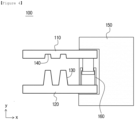
- FIGS. 4 and 5 are side cross-sectional views that show a lead gripper according to an embodiment of the present invention.
- a lead gripper 100 includes an upper arm 110 and a lower arm 120, and any one or more grip surfaces of the upper arm 110 and the lower arm 120 includes one or more lead fixing protrusions 130 that pass through the electrode lead to be gripped.
- the grip surface of the upper arm 110 or the lower arm 120 corresponding to the upper arm 110 or the lower arm 120 including the lead fixing protrusion 130 includes grooves 140 that accommodate the lead fixing protrusion 130.
- the lead gripper 100 of the present invention other configurations except for the structure of the gripper 100 can be configured in the same manner as lead grippers commonly used in this field. That is, as shown in FIG. 4 , rear end portions of the upper arm 110 and the lower arm 120 can be coupled to a lead gripper body 150. At this time, the lead gripper body 150 may include an arm moving member 160 that moves one or more of the upper arm 110 and the lower arm 120 to enable gripping.
- the arm moving member 160 can be driven by known driving means, for example, hydraulic driving means, mechanical driving means, or the like.
- the lead fixing protrusion 130 can be inserted through the electrode lead into the groove 140 that accommodates the lead fixing protrusion 130. That is, the upper end portion of the lead fixing protrusion 130 can be inserted into the groove 140 that accommodate the lead fixing protrusion, while penetrating the electrode lead.
- the electrode lead can be grasped by fitting engagement in which the lower arm 120 moves upward so that the lead fixing protrusion 130 passes through the electrode lead, and the upper arm 110 moves downward to insert the penetrated lead fixing protrusion 130 into the groove 140. Also, the electrode lead grip can be released by moving the lower arm 120 downward and moving the upper arm 110 upward to release the fitting engagement.
- the electrode lead can be transported to the electrode tab of the electrode assembly without being twisted.
- the lead fixing protrusion 130 may have a truncated conical shape or a truncated polygonal pyramid shape.
- lead fixing protrusion 130 has a truncated polygonal pyramid shape, since the lead is less likely to be twisted due to the polygonal shape, one or more lead fixing protrusions 130 may be included on the grip surface of the upper arm 110 or the lower arm 120.
- two or more lead fixing protrusions 130 may be included on the grip surface of the upper arm 110 or the lower arm 120.
- two or more lead fixing protrusions 130 may be included on the grip surface of the upper arm 110 or the lower arm 120, and the two or more lead fixing protrusions may be spaced apart from each other on the grip surface.
- FIG. 4 is a diagram showing that the two or more lead fixing protrusions 130 are located in a horizontal direction x on the basis of the tip of the arm
- FIG. 5 shows that the two or more lead fixing protrusions 130 are located in a vertical direction y.
- the lead gripper 100 may include one to three pairs of arms.
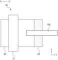
- FIGS. 6 and 7 are plan views showing the electrode lead 20 that is gripped by the lead gripper 100 according to an embodiment of the present invention.
- the electrode lead 20 includes a lead fixing hole 24 through which the lead fixing protrusion 130 can pass. Specifically, one or more lead fixing holes 24 may be included.
- the electrode lead 20 includes a joint portion 22 joined with the electrode tab, and one or more lead fixing holes 24 at one end portion, and a sealing film 21 can be placed around the electrode lead 20.
- the grip of the electrode lead 20 can be performed by making the lead fixing protrusion 130 pass through the lead fixing hole 24 formed in the electrode lead, and by inserting the lead fixing protrusion 130 having passed through the lead fixing hole 24 into the groove 140 that accommodates the lead fixing protrusion.
- the electrode lead 20 can be gripped by the fitting engagement in which the lower arm 120 moves upward to allow the lead fixing protrusion 130 to pass through the lead fixing hole 24 of the electrode lead 20, and the upper arm 110 moves downward to insert the lead fixing protrusion 130 having passed through the lead fixing hole 24 into the groove 140. Further, the grip of the electrode lead 20 can be released, by moving the lower arm 120 downward and moving the upper arm 110 upward to release the fitting engagement.
- the electrode lead 20 After the electrode lead 20 is gripped, it may be transported such that the joint portion 22 of the gripped electrode lead can be located above the electrode tab. After the transportation is completed and the grip of the electrode lead 20 is released, since the lead fixing hole 24 of the electrode lead 20 is no longer needed, it is possible to perform a step of cutting one end portion of the electrode lead 20 at which the lead fixing hole 24 is located. Cutting can be performed along a cut surface 23 of the electrode lead 20.
- the lead fixing hole 24 may have a circular or polygonal shape, and the shape of the lead fixing hole 24 can be determined depending on the shape of the lead fixing protrusion 130.
- lead fixing hole 24 may have a circular shape.
- the lead fixing holes 24 may be included in the same number as the lead fixing protrusions 130, and two or more lead fixing holes 24 may be located at one end portion of the electrode lead 20 to be separated from each other.
- FIG. 6 is a diagram showing that the two or more lead fixing holes 24 are located in the horizontal direction x on the basis of the tip of the electrode lead 20, and
- FIG. 7 is a diagram showing that the two or more lead fixing holes 24 are located in the vertical direction y.
- FIG. 8 shows that the lead gripper 100 according to one embodiment of the present invention grips the electrode lead 20.
- the lead gripper 100 can include a pair of arms. Additionally, the grip surface of one of the upper arm 110 or the lower arm 120 can include two or more lead fixing protrusions 130 that pass through the gripped electrode lead 20. The two or more lead fixing protrusions 130 may be located in the horizontal direction x or in the vertical direction y on the basis of the tip of the arm. Also, a groove 140 that accommodates the lead fixing protrusion 130 can be included on the grip surface of the upper arm 110 or the lower arm 120 corresponding to the upper arm 110 or the lower arm 120 including the lead fixing protrusion 130.
- FIG. 9 shows a lead gripper 100 according to an embodiment of the present invention.
- a lead gripper 100 can include two pairs of arms.
- the grip surface of either upper arm 110 or lower arm 120 in each pair of arms can include one or more lead fixing protrusions 130 that pass through the electrode lead 20 being gripped.
- the grip surface of the upper arm 110 or the lower arm 120 corresponding to the upper arm 110 or the lower arm 120 including the lead fixing protrusion 130 in each pair of arms may include a groove 140 that accommodates the lead fixing protrusion.
Landscapes
- Engineering & Computer Science (AREA)
- Chemical Kinetics & Catalysis (AREA)
- Electrochemistry (AREA)
- General Chemical & Material Sciences (AREA)
- Chemical & Material Sciences (AREA)
- Mechanical Engineering (AREA)
- Robotics (AREA)
- Manufacturing & Machinery (AREA)
- Connection Of Batteries Or Terminals (AREA)
- Feeding Of Articles By Means Other Than Belts Or Rollers (AREA)
- Installation Of Indoor Wiring (AREA)
- Sealing Battery Cases Or Jackets (AREA)
- Fixed Capacitors And Capacitor Manufacturing Machines (AREA)
Description
- The present invention relates to an electrode lead gripper.
- Demand for high-efficiency secondary batteries is rapidly increasing in the fields of mobile devices and electric vehicles. Among such secondary batteries, lithium secondary batteries, which have high energy density, can maintain relatively high voltage, and have a low self-discharge rate, have been commercialized and widely used, and research and development for improving performance are being actively performed.
- The lithium secondary batteries can be classified into a lithium ion battery that uses a liquid electrolyte, and a lithium ion polymer battery that uses a polymer solid electrolyte depending on the type of electrolyte.
- In the case of the lithium ion battery that uses a liquid electrolyte, it may be usually used in the form in which a cylindrical or rectangular metal can is used as a container and is welded and sealed. Since the can-type secondary battery that uses such a metal can as a container has a fixed shape, it has the drawback of restricting the design of electronic products that uses it as a power source, and it is difficult to reduce the volume. Therefore, a pouch-type secondary battery has been developed and used in which both electrodes, a separation membrane, and an electrolyte are formed into a film, put in a pouch, and sealed.
- The pouch-type secondary battery includes, as a basic structure, a battery case and an electrode assembly which are made up of a pouch or the like.
- The electrode assembly includes a positive electrode plate, a negative electrode plate, and a separation membrane interposed between the positive electrode plate and the negative electrode plate to electrically insulate the positive electrode plate and the negative electrode plate.
- As shown in
FIG. 1 , in anelectrode assembly 10, the positive elecrode plate is provided with ananode tab 12 provided on one or more regions of the positive electrode plate, and the negative electrode plate is provided with anegative electrode tab 13 provided on one or more regions of the negative electrode plate. After the one or morepositive electrode tabs 12 andnegative electrode tabs 13 converge in a certain direction, they are joined to theelectrode lead 20 made of a conductive material by a method such as general resistance welding, ultrasonic welding, laser welding, and riveting. At this time, asealing film 21 may be disposed around theelectrode lead 20 to ensure an insulated state at a contact portion with the battery case and to increase the degree of sealing. - The
electrode lead 20 connected and extending in this way performs a function corresponding to a predetermined electrode interface for electrically connecting the secondary battery and an external application device. - In order to bond the
electrode lead 20 to theelectrode tabs electrode lead 20 needs to be transported so as to be located above theelectrode tabs electrode lead 20 is transported using a manner of gripping and transporting theelectrode lead 20 by thegripper 200, and is a manner of applying pressure to theelectrode lead 20 with thegripper 200 to fix theelectrode lead 20 and transporting it to theelectrode tabs electrode assembly 10. -
FIG. 2 is a side cross-sectional view showing that the gripper 210 grips the electrode lead 20 in the above-described conventional manner, and in which theelectrode lead 20 having a flat surface is gripped using thegripper 200 having a flat grip surface. - However, if the electrode lead 20 and the grip surface are flat as described above, when a change occurs in pressure or surface friction, a phenomenon in which the
electrode lead 20 is twisted as shown inFIG. 3 may occur, which may cause dimensional defects in the battery. - Therefore, there is an emerging need for an electrode lead gripper that can solve the above problems.
-
JPH0722542 U -
-
Korean Patent Application No. 10-2014-0133140 -
Korean Patent Application No. 10-2012-0016905 - An object of the present invention is to provide an electrode lead gripper that can transport the electrode lead without twisting the electrode lead, even if pressure or friction changes, by fixing the electrode lead using a gripper.
- In order to achieve the above purpose,
the present invention provides a lead gripper that grips and transports an electrode lead as recited in independent claim 1. - In an aspect of the present invention, the lead fixing protrusion may pass through the electrode lead and may be inserted into the groove which accommodates the lead fixing protrusion.
- In an aspect of the present invention, the lead fixing protrusion may have a truncated conical shape or a truncated polygonal pyramid shape.
- In an aspect of the present invention, the lead fixing protrusion may have the truncated conical shape.
- In an aspect of the present invention, the two or more lead fixing protrusions may be included, and the two or more lead fixing protrusions may be located on the grip surface to be spaced apart from each other.
- In an aspect of the present invention, the two or more lead fixing protrusions may be located in a horizontal direction or in a vertical direction on the basis of a tip of the arm.
- In an aspect of the present invention, the lead gripper may include one to three pairs of arms.
- In an aspect of the present invention, the lead fixing hole may have a circular or polygonal shape.
- In an aspect of the present invention, the lead fixing hole may have a circular shape.
- In an aspect of the present invention, the lead gripper may include a pair of arms,
- the grip surface of any one of the upper arm or the lower arm may include two or more lead fixing protrusions that pass through the gripped electrode lead,
- the two or more lead fixing protrusions may be located in the horizontal direction or in the vertical direction on the basis of the tip of the arm, and
- the grip surface of the upper arm or the lower arm corresponding to the upper arm or the lower arm including the lead fixing protrusion may include a groove that accommodates the lead fixing protrusion.
- In an aspect of the present invention, the lead gripper may include two or more pairs of arms,
- the grip surface of any one of the upper arm or the lower arm in each pair of arms may include one or more lead fixing protrusions that pass through the gripped electrode lead, and
- the grip surface of the upper arm or the lower arm corresponding to the upper arm or the lower arm including the lead fixing protrusion in each pair of arms may include a groove that accommodates the lead fixing protrusion.
- Since the lead gripper of the present invention can fix the electrode lead by the lead fixing protrusion that passes through the electrode lead, it is possible to grip and transport the electrode lead without twisting the electrode lead even when pressure and friction change. This makes it possible to solve problems such as dimensional defects of the battery.
-
-
FIG. 1 is a perspective view of an electrode assembly. -
FIG. 2 is a side sectional view showing a status in which a conventional electrode lead gripper grips the electrode lead. -
FIG. 3 is a plan view showing a lead twisting phenomenon that occurs in the conventional electrode lead transportation. -
FIG. 4 is a side cross-sectional view of a lead gripper according to an embodiment of the present invention. -
FIG. 5 is a front view of a lead gripper according to an embodiment of the present invention. -
FIG. 6 is a plan view of the electrode lead gripped by the lead gripper according to an embodiment of the present invention. -
FIG. 7 is a plan view of the electrode lead gripped by the lead gripper according to an embodiment of the present invention. -
FIG. 8 is a plan view of the lead gripper that grips the electrode lead according to an embodiment of the present invention. -
FIG. 9 is a plan view of the lead gripper that grips the electrode lead according to an embodiment of the present invention. - Hereinafter, the present invention will be described in detail based on the accompanying drawings so that a person having ordinary knowledge in the technical field to which the present invention belongs can easily carry it out. This invention may, however, be embodied in many different forms and is not limited to the embodiments set forth herein.
- In order to clearly describe the present invention, parts irrelevant to the description have been omitted, and the same or similar components are denoted by the same reference numerals throughout the specification.
- Furthermore, terms or words used in the specification and claims should not be construed as being limited to its customary or dictionary meaning, and should be interpreted by the inventors as a meaning and concept consistent with the technical idea of the present invention, based on the principle that the concepts of the terms can be properly defined to describe their invention in the best possible manner.
- Embodiments will now be described in detail with reference to the accompanying drawings. This invention may, however, be embodied in many different forms and is not limited to the embodiments set forth herein.
-
FIGS. 4 and5 are side cross-sectional views that show a lead gripper according to an embodiment of the present invention. - Referring to
FIGS. 4 and5 , alead gripper 100 according to one embodiment of the present invention includes anupper arm 110 and alower arm 120, and any one or more grip surfaces of theupper arm 110 and thelower arm 120 includes one or morelead fixing protrusions 130 that pass through the electrode lead to be gripped. - Also, the grip surface of the
upper arm 110 or thelower arm 120 corresponding to theupper arm 110 or thelower arm 120 including thelead fixing protrusion 130 includesgrooves 140 that accommodate thelead fixing protrusion 130. - In the
lead gripper 100 of the present invention, other configurations except for the structure of thegripper 100 can be configured in the same manner as lead grippers commonly used in this field. That is, as shown inFIG. 4 , rear end portions of theupper arm 110 and thelower arm 120 can be coupled to alead gripper body 150. At this time, thelead gripper body 150 may include anarm moving member 160 that moves one or more of theupper arm 110 and thelower arm 120 to enable gripping. Thearm moving member 160 can be driven by known driving means, for example, hydraulic driving means, mechanical driving means, or the like. - In the
lead gripper 100 of the present invention, thelead fixing protrusion 130 can be inserted through the electrode lead into thegroove 140 that accommodates thelead fixing protrusion 130. That is, the upper end portion of thelead fixing protrusion 130 can be inserted into thegroove 140 that accommodate the lead fixing protrusion, while penetrating the electrode lead. - For example, when the
lower arm 120 includes thelead fixing protrusion 130, and theupper arm 110 includes thegroove 140 for accommodating thelead fixing protrusion 130, the electrode lead can be grasped by fitting engagement in which thelower arm 120 moves upward so that thelead fixing protrusion 130 passes through the electrode lead, and theupper arm 110 moves downward to insert the penetratedlead fixing protrusion 130 into thegroove 140. Also, the electrode lead grip can be released by moving thelower arm 120 downward and moving theupper arm 110 upward to release the fitting engagement. - Due to the fitting engagement, the electrode lead can be transported to the electrode tab of the electrode assembly without being twisted.
- The
lead fixing protrusion 130 may have a truncated conical shape or a truncated polygonal pyramid shape. - If the
lead fixing protrusion 130 has a truncated polygonal pyramid shape, since the lead is less likely to be twisted due to the polygonal shape, one or morelead fixing protrusions 130 may be included on the grip surface of theupper arm 110 or thelower arm 120. - In addition, when the
lead fixing protrusion 130 has a truncated conical shape, since the penetratedlead fixing protrusion 130 is easily twisted, two or morelead fixing protrusions 130 may be included on the grip surface of theupper arm 110 or thelower arm 120. - Preferably, two or more
lead fixing protrusions 130 may be included on the grip surface of theupper arm 110 or thelower arm 120, and the two or more lead fixing protrusions may be spaced apart from each other on the grip surface. -
FIG. 4 is a diagram showing that the two or morelead fixing protrusions 130 are located in a horizontal direction x on the basis of the tip of the arm, andFIG. 5 shows that the two or morelead fixing protrusions 130 are located in a vertical direction y. - The
lead gripper 100 may include one to three pairs of arms. -
FIGS. 6 and7 are plan views showing theelectrode lead 20 that is gripped by thelead gripper 100 according to an embodiment of the present invention. - In order for the
lead fixing protrusion 130 of thelead gripper 100 to pass through theelectrode lead 20, theelectrode lead 20 includes alead fixing hole 24 through which thelead fixing protrusion 130 can pass. Specifically, one or morelead fixing holes 24 may be included. - Referring to
FIGS. 6 and7 , theelectrode lead 20 includes ajoint portion 22 joined with the electrode tab, and one or morelead fixing holes 24 at one end portion, and a sealingfilm 21 can be placed around theelectrode lead 20. - The grip of the
electrode lead 20 can be performed by making thelead fixing protrusion 130 pass through thelead fixing hole 24 formed in the electrode lead, and by inserting thelead fixing protrusion 130 having passed through thelead fixing hole 24 into thegroove 140 that accommodates the lead fixing protrusion. - For example, when the
lower arm 120 includes thelead fixing protrusion 130 and theupper arm 110 includes thegroove 140 that accommodates thelead fixing protrusion 130, theelectrode lead 20 can be gripped by the fitting engagement in which thelower arm 120 moves upward to allow thelead fixing protrusion 130 to pass through thelead fixing hole 24 of theelectrode lead 20, and theupper arm 110 moves downward to insert thelead fixing protrusion 130 having passed through thelead fixing hole 24 into thegroove 140. Further, the grip of theelectrode lead 20 can be released, by moving thelower arm 120 downward and moving theupper arm 110 upward to release the fitting engagement. - After the
electrode lead 20 is gripped, it may be transported such that thejoint portion 22 of the gripped electrode lead can be located above the electrode tab. After the transportation is completed and the grip of theelectrode lead 20 is released, since thelead fixing hole 24 of theelectrode lead 20 is no longer needed, it is possible to perform a step of cutting one end portion of theelectrode lead 20 at which thelead fixing hole 24 is located. Cutting can be performed along acut surface 23 of theelectrode lead 20. - The
lead fixing hole 24 may have a circular or polygonal shape, and the shape of thelead fixing hole 24 can be determined depending on the shape of thelead fixing protrusion 130. Preferably, lead fixinghole 24 may have a circular shape. - Also, the
lead fixing holes 24 may be included in the same number as thelead fixing protrusions 130, and two or morelead fixing holes 24 may be located at one end portion of theelectrode lead 20 to be separated from each other. -
FIG. 6 is a diagram showing that the two or morelead fixing holes 24 are located in the horizontal direction x on the basis of the tip of theelectrode lead 20, andFIG. 7 is a diagram showing that the two or morelead fixing holes 24 are located in the vertical direction y. -
FIG. 8 shows that thelead gripper 100 according to one embodiment of the present invention grips theelectrode lead 20. - Referring to
FIG. 8 , thelead gripper 100 according to an embodiment of the present invention can include a pair of arms. Additionally, the grip surface of one of theupper arm 110 or thelower arm 120 can include two or morelead fixing protrusions 130 that pass through the grippedelectrode lead 20. The two or morelead fixing protrusions 130 may be located in the horizontal direction x or in the vertical direction y on the basis of the tip of the arm. Also, agroove 140 that accommodates thelead fixing protrusion 130 can be included on the grip surface of theupper arm 110 or thelower arm 120 corresponding to theupper arm 110 or thelower arm 120 including thelead fixing protrusion 130. -
FIG. 9 shows alead gripper 100 according to an embodiment of the present invention. - Referring to
FIG. 9 , alead gripper 100 according to one embodiment of the present invention can include two pairs of arms. The grip surface of eitherupper arm 110 orlower arm 120 in each pair of arms can include one or morelead fixing protrusions 130 that pass through theelectrode lead 20 being gripped. At this time, the grip surface of theupper arm 110 or thelower arm 120 corresponding to theupper arm 110 or thelower arm 120 including thelead fixing protrusion 130 in each pair of arms may include agroove 140 that accommodates the lead fixing protrusion. -
- 10: Electrode assembly, 12: Positive electrode tab
- 13: Negative electrode tab 20: Electrode lead
- 21: Sealing film, 22: Joint portion
- 23: Cut surface, 24: Lead fixing hole
- 100, 200: Lead gripper, 110: Upper arm
- 120: Lower arm, 130: Lead fixing protrusion
- 140: Groove, 150: Lead gripper body
- 160: Arm moving member
- 23: Cut surface, 24: Lead fixing hole
- 100, 200: Lead gripper, 110: Upper arm
- 120: Lower arm, 130: Lead fixing protrusion
- 140: Groove, 150: Lead gripper body
- 160: Arm moving member
Claims (11)
- A lead gripper (100,200) that is configured to grip and transport an electrode lead (20),wherein the lead gripper (100,200) comprises an upper arm (110) and a lower arm (120),wherein one or more grip surfaces of any one of the upper arm (110) and the lower arm (120) comprise one or more lead fixing protrusions (130) that are configured topass through one or more lead fixing holes (24) in the electrode lead to be gripped; andcharacterized in that a grip surface of the upper arm (110) or the lower arm (120) corresponding to the upper arm (110) or the lower arm (120) comprising the lead fixing protrusion (130) comprises a groove (140) which is configured to accommodate the lead fixing protrusion (130).
- The lead gripper (100,200) according to claim 1,
wherein the lead fixing protrusion (130) is configured to pass through the electrode lead and is configured to be inserted into the groove (140) which is configured to accommodate the lead fixing protrusion (130). - The lead gripper (100,200) according to claim 1,
wherein the lead fixing protrusion (130) has a truncated conical shape or a truncated polygonal pyramid shape. - The lead gripper (100,200) according to claim 3,
wherein the lead fixing protrusion (130) has a truncated conical shape. - The lead gripper (100,200) according to claim 1,wherein two or more lead fixing protrusions (130) are comprised, andthe two or more lead fixing protrusions (130) are located on the grip surface to be spaced apart from each other.
- The lead gripper (100,200) according to claim 5,
wherein the two or more lead fixing protrusions (130) are located in a horizontal direction or in a vertical direction on the basis of a tip of arm. - The lead gripper (100,200) according to claim 1,
wherein the lead gripper (100, 200) comprises one to three pairs of arms. - A system comprising a lead gripper (100,200) and an electrode lead (20) according to claim 1,
wherein the lead fixing hole has a circular or polygonal shape. - The system according to claim 8,
wherein the lead fixing hole has a circular shape. - The lead gripper (100,200) according to claim 1,wherein the lead gripper (100, 200) comprises a pair of arms,a grip surface of any one of the upper arm (110) or the lower arm (120) comprises two or more lead fixing protrusions (130) that are configured to pass through the gripped electrode lead (20),the two or more lead fixing protrusions (130) are located in a horizontal direction or in a vertical direction on the basis of the tip of the arm, anda grip surface of an upper arm (110) or a lower arm (120) corresponding to an upper arm (110) or a lower arm (120) comprising the lead fixing protrusion (130) comprises a groove (140) that is configured to accommodate the lead fixing protrusion (130).
- The lead gripper (100,200) according to claim 1,wherein the lead gripper (100,200) comprises two or more pairs of arms,a grip surface of any one of an upper arm (110) or a lower arm (120) in each pair of arms comprises one or more lead fixing protrusions (130) that are configured to pass through the gripped electrode lead (20), anda grip surface of an upper arm (110) or a lower arm (120) corresponding to an upper arm (110) or a lower arm (120) comprising the lead fixing protrusion (130) in each pair of arms comprises a groove (140) that is configured to accommodate the lead fixing protrusion (130).
Applications Claiming Priority (2)
| Application Number | Priority Date | Filing Date | Title |
|---|---|---|---|
| KR1020210129232A KR102940369B1 (en) | 2021-09-29 | 2021-09-29 | Electrode lead gripper |
| PCT/KR2022/014467 WO2023055035A1 (en) | 2021-09-29 | 2022-09-27 | Electrode lead gripper |
Publications (3)
| Publication Number | Publication Date |
|---|---|
| EP4258456A1 EP4258456A1 (en) | 2023-10-11 |
| EP4258456A4 EP4258456A4 (en) | 2024-07-24 |
| EP4258456B1 true EP4258456B1 (en) | 2025-05-14 |
Family
ID=85783148
Family Applications (1)
| Application Number | Title | Priority Date | Filing Date |
|---|---|---|---|
| EP22876807.3A Active EP4258456B1 (en) | 2021-09-29 | 2022-09-27 | Electrode lead gripper |
Country Status (8)
| Country | Link |
|---|---|
| US (1) | US20240157578A1 (en) |
| EP (1) | EP4258456B1 (en) |
| JP (1) | JP7515724B2 (en) |
| KR (1) | KR102940369B1 (en) |
| CN (1) | CN116601827A (en) |
| ES (1) | ES3032215T3 (en) |
| HU (1) | HUE071687T2 (en) |
| WO (1) | WO2023055035A1 (en) |
Family Cites Families (9)
| Publication number | Priority date | Publication date | Assignee | Title |
|---|---|---|---|---|
| JPS63110099U (en) * | 1987-01-07 | 1988-07-15 | ||
| JP2566734Y2 (en) * | 1993-09-16 | 1998-03-30 | 住友精密工業株式会社 | Transfer hand |
| KR101254691B1 (en) | 2010-08-17 | 2013-04-15 | 주식회사 엘지화학 | Secondary electric cell with enhanced lead structure |
| KR101359902B1 (en) * | 2011-01-31 | 2014-02-07 | 주식회사 엘지화학 | Jig for Charging and Discharging of Battery Cell |
| KR101905079B1 (en) * | 2011-12-21 | 2018-10-08 | 삼성에스디아이 주식회사 | Secondary Battery |
| KR20140048622A (en) * | 2012-10-16 | 2014-04-24 | 주식회사 엘지화학 | Electrode assembly and containing the electrode assembly, electrochemical cell |
| KR101486232B1 (en) | 2013-05-10 | 2015-01-26 | 주식회사 엘지화학 | Apparatus Transferring Battery Cell |
| KR102165327B1 (en) * | 2017-04-04 | 2020-10-13 | 주식회사 엘지화학 | Jig for contact between two electrode leads and welding method of electrode leads |
| TWI901065B (en) | 2019-03-15 | 2025-10-11 | 美商蘭姆研究公司 | Friction stir welding in semiconductor manufacturing applications |
-
2021
- 2021-09-29 KR KR1020210129232A patent/KR102940369B1/en active Active
-
2022
- 2022-09-27 US US18/283,914 patent/US20240157578A1/en active Pending
- 2022-09-27 ES ES22876807T patent/ES3032215T3/en active Active
- 2022-09-27 EP EP22876807.3A patent/EP4258456B1/en active Active
- 2022-09-27 HU HUE22876807A patent/HUE071687T2/en unknown
- 2022-09-27 WO PCT/KR2022/014467 patent/WO2023055035A1/en not_active Ceased
- 2022-09-27 CN CN202280007552.8A patent/CN116601827A/en active Pending
- 2022-09-27 JP JP2023532824A patent/JP7515724B2/en active Active
Also Published As
| Publication number | Publication date |
|---|---|
| KR102940369B1 (en) | 2026-03-16 |
| EP4258456A4 (en) | 2024-07-24 |
| ES3032215T3 (en) | 2025-07-16 |
| US20240157578A1 (en) | 2024-05-16 |
| WO2023055035A1 (en) | 2023-04-06 |
| HUE071687T2 (en) | 2025-09-28 |
| JP2024501619A (en) | 2024-01-15 |
| KR20230046127A (en) | 2023-04-05 |
| JP7515724B2 (en) | 2024-07-12 |
| CN116601827A (en) | 2023-08-15 |
| EP4258456A1 (en) | 2023-10-11 |
Similar Documents
| Publication | Publication Date | Title |
|---|---|---|
| CN110692149B (en) | Battery module, battery pack including the same, and vehicle | |
| KR100905390B1 (en) | Pouch type secondary battery improves safety by preventing internal flow of electrode assembly | |
| US9196886B2 (en) | Secondary battery having insulation bag | |
| CN112956061A (en) | Secondary battery | |
| KR20150113758A (en) | Battery Pack and method for manufacturing the same | |
| KR20190087871A (en) | Secondary battery | |
| KR20170060446A (en) | Secondary Battery | |
| KR20170060448A (en) | Secondary Battery and Method for Manufacturing The Same | |
| KR20170060447A (en) | A secondary battery | |
| KR20160046477A (en) | Battery cell, and battery module | |
| KR101945901B1 (en) | Secondary battery | |
| JP7489406B2 (en) | Cell battery | |
| KR101616502B1 (en) | Secondary battery having electrode lid and electrode tab connected by slit | |
| KR102086036B1 (en) | Battery Cell Comprising Cylindrical Can Having Screw-typed Fastening Portion | |
| EP4258456A1 (en) | Electrode lead gripper | |
| KR20170034122A (en) | Secondary Battery | |
| US20220223986A1 (en) | Cell battery | |
| KR101302075B1 (en) | Couple structure of electrode tab and terminal for secondary battery and Secondary battery having the same | |
| KR101805232B1 (en) | Battery cell having a combination structure with rivet | |
| KR20080003473A (en) | Secondary battery with improved sealing at case heat-sealed portion | |
| KR100936259B1 (en) | Secondary battery pack with excellent manufacturing processability and structural stability | |
| KR100601529B1 (en) | Connection lead soldering method and pouch type lithium polymer battery using same | |
| KR102558420B1 (en) | Secondary battery | |
| KR101783920B1 (en) | Battery lead to be connected to cable and manufacturing method thereof | |
| EP4693426A1 (en) | Electrode plate for secondary battery, battery cell comprising electrode plate for secondary battery, and method for manufacturing electrode plate for secondary battery |
Legal Events
| Date | Code | Title | Description |
|---|---|---|---|
| STAA | Information on the status of an ep patent application or granted ep patent |
Free format text: STATUS: THE INTERNATIONAL PUBLICATION HAS BEEN MADE |
|
| PUAI | Public reference made under article 153(3) epc to a published international application that has entered the european phase |
Free format text: ORIGINAL CODE: 0009012 |
|
| STAA | Information on the status of an ep patent application or granted ep patent |
Free format text: STATUS: REQUEST FOR EXAMINATION WAS MADE |
|
| 17P | Request for examination filed |
Effective date: 20230616 |
|
| AK | Designated contracting states |
Kind code of ref document: A1 Designated state(s): AL AT BE BG CH CY CZ DE DK EE ES FI FR GB GR HR HU IE IS IT LI LT LU LV MC MK MT NL NO PL PT RO RS SE SI SK SM TR |
|
| XX | Miscellaneous (additional remarks) |
Free format text: A REQUEST FOR CORRECTION OF THE DESCRIPTION HAS BEEN FILED ON 16.06.2023 PURSUANT TO RULE 139 EPC. A DECISION ON THE REQUEST WILL BE TAKEN DURING THE PROCEEDINGS BEFORE THE EXAMINING DIVISION (GUIDELINES FOR EXAMINATION IN THE EPO, A-V, 3). |
|
| A4 | Supplementary search report drawn up and despatched |
Effective date: 20240626 |
|
| RIC1 | Information provided on ipc code assigned before grant |
Ipc: H01M 50/54 20210101ALI20240620BHEP Ipc: H01M 50/567 20210101ALI20240620BHEP Ipc: B25J 15/02 20060101ALI20240620BHEP Ipc: B25J 15/00 20060101ALI20240620BHEP Ipc: B65H 5/14 20060101ALI20240620BHEP Ipc: H01M 50/531 20210101ALI20240620BHEP Ipc: H01M 50/557 20210101AFI20240620BHEP |
|
| GRAP | Despatch of communication of intention to grant a patent |
Free format text: ORIGINAL CODE: EPIDOSNIGR1 |
|
| STAA | Information on the status of an ep patent application or granted ep patent |
Free format text: STATUS: GRANT OF PATENT IS INTENDED |
|
| DAV | Request for validation of the european patent (deleted) | ||
| DAX | Request for extension of the european patent (deleted) | ||
| RIC1 | Information provided on ipc code assigned before grant |
Ipc: H01M 50/54 20210101ALI20241212BHEP Ipc: H01M 50/567 20210101ALI20241212BHEP Ipc: B25J 15/02 20060101ALI20241212BHEP Ipc: B25J 15/00 20060101ALI20241212BHEP Ipc: B65H 5/14 20060101ALI20241212BHEP Ipc: H01M 50/531 20210101ALI20241212BHEP Ipc: H01M 50/557 20210101AFI20241212BHEP |
|
| INTG | Intention to grant announced |
Effective date: 20241219 |
|
| P01 | Opt-out of the competence of the unified patent court (upc) registered |
Free format text: CASE NUMBER: APP_598/2025 Effective date: 20250107 |
|
| GRAS | Grant fee paid |
Free format text: ORIGINAL CODE: EPIDOSNIGR3 |
|
| GRAA | (expected) grant |
Free format text: ORIGINAL CODE: 0009210 |
|
| STAA | Information on the status of an ep patent application or granted ep patent |
Free format text: STATUS: THE PATENT HAS BEEN GRANTED |
|
| AK | Designated contracting states |
Kind code of ref document: B1 Designated state(s): AL AT BE BG CH CY CZ DE DK EE ES FI FR GB GR HR HU IE IS IT LI LT LU LV MC MK MT NL NO PL PT RO RS SE SI SK SM TR |
|
| REG | Reference to a national code |
Ref country code: GB Ref legal event code: FG4D |
|
| XX | Miscellaneous (additional remarks) |
Free format text: A REQUEST FOR CORRECTION OF THE DESCRIPTION HAS BEEN FILED ON 16.06.2023 PURSUANT TO RULE 139 EPC. A DECISION ON THE REQUEST WILL BE TAKEN DURING THE PROCEEDINGS BEFORE THE EXAMINING DIVISION (GUIDELINES FOR EXAMINATION IN THE EPO, A-V, 3). |
|
| REG | Reference to a national code |
Ref country code: CH Ref legal event code: EP |
|
| REG | Reference to a national code |
Ref country code: DE Ref legal event code: R096 Ref document number: 602022014789 Country of ref document: DE |
|
| REG | Reference to a national code |
Ref country code: IE Ref legal event code: FG4D |
|
| REG | Reference to a national code |
Ref country code: ES Ref legal event code: FG2A Ref document number: 3032215 Country of ref document: ES Kind code of ref document: T3 Effective date: 20250716 |
|
| REG | Reference to a national code |
Ref country code: NL Ref legal event code: MP Effective date: 20250514 |
|
| REG | Reference to a national code |
Ref country code: HU Ref legal event code: AG4A Ref document number: E071687 Country of ref document: HU |
|
| PG25 | Lapsed in a contracting state [announced via postgrant information from national office to epo] |
Ref country code: PT Free format text: LAPSE BECAUSE OF FAILURE TO SUBMIT A TRANSLATION OF THE DESCRIPTION OR TO PAY THE FEE WITHIN THE PRESCRIBED TIME-LIMIT Effective date: 20250915 Ref country code: FI Free format text: LAPSE BECAUSE OF FAILURE TO SUBMIT A TRANSLATION OF THE DESCRIPTION OR TO PAY THE FEE WITHIN THE PRESCRIBED TIME-LIMIT Effective date: 20250514 |
|
| PGFP | Annual fee paid to national office [announced via postgrant information from national office to epo] |
Ref country code: DE Payment date: 20250820 Year of fee payment: 4 |
|
| REG | Reference to a national code |
Ref country code: LT Ref legal event code: MG9D |
|
| PG25 | Lapsed in a contracting state [announced via postgrant information from national office to epo] |
Ref country code: GR Free format text: LAPSE BECAUSE OF FAILURE TO SUBMIT A TRANSLATION OF THE DESCRIPTION OR TO PAY THE FEE WITHIN THE PRESCRIBED TIME-LIMIT Effective date: 20250815 Ref country code: NO Free format text: LAPSE BECAUSE OF FAILURE TO SUBMIT A TRANSLATION OF THE DESCRIPTION OR TO PAY THE FEE WITHIN THE PRESCRIBED TIME-LIMIT Effective date: 20250814 |
|
| PG25 | Lapsed in a contracting state [announced via postgrant information from national office to epo] |
Ref country code: NL Free format text: LAPSE BECAUSE OF FAILURE TO SUBMIT A TRANSLATION OF THE DESCRIPTION OR TO PAY THE FEE WITHIN THE PRESCRIBED TIME-LIMIT Effective date: 20250514 Ref country code: PL Free format text: LAPSE BECAUSE OF FAILURE TO SUBMIT A TRANSLATION OF THE DESCRIPTION OR TO PAY THE FEE WITHIN THE PRESCRIBED TIME-LIMIT Effective date: 20250514 |
|
| REG | Reference to a national code |
Ref country code: AT Ref legal event code: MK05 Ref document number: 1795629 Country of ref document: AT Kind code of ref document: T Effective date: 20250514 |
|
| PG25 | Lapsed in a contracting state [announced via postgrant information from national office to epo] |
Ref country code: BG Free format text: LAPSE BECAUSE OF FAILURE TO SUBMIT A TRANSLATION OF THE DESCRIPTION OR TO PAY THE FEE WITHIN THE PRESCRIBED TIME-LIMIT Effective date: 20250514 |
|
| PGFP | Annual fee paid to national office [announced via postgrant information from national office to epo] |
Ref country code: HU Payment date: 20250929 Year of fee payment: 4 Ref country code: BE Payment date: 20250820 Year of fee payment: 4 |
|
| PG25 | Lapsed in a contracting state [announced via postgrant information from national office to epo] |
Ref country code: HR Free format text: LAPSE BECAUSE OF FAILURE TO SUBMIT A TRANSLATION OF THE DESCRIPTION OR TO PAY THE FEE WITHIN THE PRESCRIBED TIME-LIMIT Effective date: 20250514 |
|
| PG25 | Lapsed in a contracting state [announced via postgrant information from national office to epo] |
Ref country code: AT Free format text: LAPSE BECAUSE OF FAILURE TO SUBMIT A TRANSLATION OF THE DESCRIPTION OR TO PAY THE FEE WITHIN THE PRESCRIBED TIME-LIMIT Effective date: 20250514 |
|
| PGFP | Annual fee paid to national office [announced via postgrant information from national office to epo] |
Ref country code: FR Payment date: 20250821 Year of fee payment: 4 |
|
| PG25 | Lapsed in a contracting state [announced via postgrant information from national office to epo] |
Ref country code: RS Free format text: LAPSE BECAUSE OF FAILURE TO SUBMIT A TRANSLATION OF THE DESCRIPTION OR TO PAY THE FEE WITHIN THE PRESCRIBED TIME-LIMIT Effective date: 20250814 |
|
| PG25 | Lapsed in a contracting state [announced via postgrant information from national office to epo] |
Ref country code: IS Free format text: LAPSE BECAUSE OF FAILURE TO SUBMIT A TRANSLATION OF THE DESCRIPTION OR TO PAY THE FEE WITHIN THE PRESCRIBED TIME-LIMIT Effective date: 20250914 |
|
| PG25 | Lapsed in a contracting state [announced via postgrant information from national office to epo] |
Ref country code: LV Free format text: LAPSE BECAUSE OF FAILURE TO SUBMIT A TRANSLATION OF THE DESCRIPTION OR TO PAY THE FEE WITHIN THE PRESCRIBED TIME-LIMIT Effective date: 20250514 |
|
| PG25 | Lapsed in a contracting state [announced via postgrant information from national office to epo] |
Ref country code: SM Free format text: LAPSE BECAUSE OF FAILURE TO SUBMIT A TRANSLATION OF THE DESCRIPTION OR TO PAY THE FEE WITHIN THE PRESCRIBED TIME-LIMIT Effective date: 20250514 Ref country code: DK Free format text: LAPSE BECAUSE OF FAILURE TO SUBMIT A TRANSLATION OF THE DESCRIPTION OR TO PAY THE FEE WITHIN THE PRESCRIBED TIME-LIMIT Effective date: 20250514 |
|
| PG25 | Lapsed in a contracting state [announced via postgrant information from national office to epo] |
Ref country code: CZ Free format text: LAPSE BECAUSE OF FAILURE TO SUBMIT A TRANSLATION OF THE DESCRIPTION OR TO PAY THE FEE WITHIN THE PRESCRIBED TIME-LIMIT Effective date: 20250514 |
|
| PG25 | Lapsed in a contracting state [announced via postgrant information from national office to epo] |
Ref country code: EE Free format text: LAPSE BECAUSE OF FAILURE TO SUBMIT A TRANSLATION OF THE DESCRIPTION OR TO PAY THE FEE WITHIN THE PRESCRIBED TIME-LIMIT Effective date: 20250514 |
|
| PG25 | Lapsed in a contracting state [announced via postgrant information from national office to epo] |
Ref country code: SK Free format text: LAPSE BECAUSE OF FAILURE TO SUBMIT A TRANSLATION OF THE DESCRIPTION OR TO PAY THE FEE WITHIN THE PRESCRIBED TIME-LIMIT Effective date: 20250514 |
|
| PG25 | Lapsed in a contracting state [announced via postgrant information from national office to epo] |
Ref country code: IT Free format text: LAPSE BECAUSE OF FAILURE TO SUBMIT A TRANSLATION OF THE DESCRIPTION OR TO PAY THE FEE WITHIN THE PRESCRIBED TIME-LIMIT Effective date: 20250514 |
|
| PGFP | Annual fee paid to national office [announced via postgrant information from national office to epo] |
Ref country code: ES Payment date: 20251007 Year of fee payment: 4 |
|
| REG | Reference to a national code |
Ref country code: DE Ref legal event code: R097 Ref document number: 602022014789 Country of ref document: DE |
|
| PG25 | Lapsed in a contracting state [announced via postgrant information from national office to epo] |
Ref country code: RO Free format text: LAPSE BECAUSE OF FAILURE TO SUBMIT A TRANSLATION OF THE DESCRIPTION OR TO PAY THE FEE WITHIN THE PRESCRIBED TIME-LIMIT Effective date: 20250514 |
|
| PLBE | No opposition filed within time limit |
Free format text: ORIGINAL CODE: 0009261 |
|
| STAA | Information on the status of an ep patent application or granted ep patent |
Free format text: STATUS: NO OPPOSITION FILED WITHIN TIME LIMIT |
|
| REG | Reference to a national code |
Ref country code: CH Ref legal event code: L10 Free format text: ST27 STATUS EVENT CODE: U-0-0-L10-L00 (AS PROVIDED BY THE NATIONAL OFFICE) Effective date: 20260325 |
|
| 26N | No opposition filed |
Effective date: 20260217 |
|
| REG | Reference to a national code |
Ref country code: CH Ref legal event code: H13 Free format text: ST27 STATUS EVENT CODE: U-0-0-H10-H13 (AS PROVIDED BY THE NATIONAL OFFICE) Effective date: 20260504 |