EP4258455A1 - Foil tab forming apparatus and foil tab forming method - Google Patents
Foil tab forming apparatus and foil tab forming method Download PDFInfo
- Publication number
- EP4258455A1 EP4258455A1 EP22767487.6A EP22767487A EP4258455A1 EP 4258455 A1 EP4258455 A1 EP 4258455A1 EP 22767487 A EP22767487 A EP 22767487A EP 4258455 A1 EP4258455 A1 EP 4258455A1
- Authority
- EP
- European Patent Office
- Prior art keywords
- foil tab
- pressing block
- electrode assembly
- pressing
- forming
- Prior art date
- Legal status (The legal status is an assumption and is not a legal conclusion. Google has not performed a legal analysis and makes no representation as to the accuracy of the status listed.)
- Granted
Links
Images





Classifications
-
- B—PERFORMING OPERATIONS; TRANSPORTING
- B21—MECHANICAL METAL-WORKING WITHOUT ESSENTIALLY REMOVING MATERIAL; PUNCHING METAL
- B21D—WORKING OR PROCESSING OF SHEET METAL OR METAL TUBES, RODS OR PROFILES WITHOUT ESSENTIALLY REMOVING MATERIAL; PUNCHING METAL
- B21D11/00—Bending not restricted to forms of material mentioned in only one of groups B21D5/00, B21D7/00, B21D9/00; Bending not provided for in groups B21D5/00 - B21D9/00; Twisting
- B21D11/10—Bending specially adapted to produce specific articles, e.g. leaf springs
-
- H—ELECTRICITY
- H01—ELECTRIC ELEMENTS
- H01M—PROCESSES OR MEANS, e.g. BATTERIES, FOR THE DIRECT CONVERSION OF CHEMICAL ENERGY INTO ELECTRICAL ENERGY
- H01M50/00—Constructional details or processes of manufacture of the non-active parts of electrochemical cells other than fuel cells, e.g. hybrid cells
- H01M50/50—Current conducting connections for cells or batteries
- H01M50/531—Electrode connections inside a battery casing
- H01M50/538—Connection of several leads or tabs of wound or folded electrode stacks
-
- B—PERFORMING OPERATIONS; TRANSPORTING
- B21—MECHANICAL METAL-WORKING WITHOUT ESSENTIALLY REMOVING MATERIAL; PUNCHING METAL
- B21D—WORKING OR PROCESSING OF SHEET METAL OR METAL TUBES, RODS OR PROFILES WITHOUT ESSENTIALLY REMOVING MATERIAL; PUNCHING METAL
- B21D33/00—Special measures in connection with working metal foils, e.g. gold foils
-
- B—PERFORMING OPERATIONS; TRANSPORTING
- B21—MECHANICAL METAL-WORKING WITHOUT ESSENTIALLY REMOVING MATERIAL; PUNCHING METAL
- B21D—WORKING OR PROCESSING OF SHEET METAL OR METAL TUBES, RODS OR PROFILES WITHOUT ESSENTIALLY REMOVING MATERIAL; PUNCHING METAL
- B21D11/00—Bending not restricted to forms of material mentioned in only one of groups B21D5/00, B21D7/00, B21D9/00; Bending not provided for in groups B21D5/00 - B21D9/00; Twisting
- B21D11/20—Bending sheet metal, not otherwise provided for
-
- B—PERFORMING OPERATIONS; TRANSPORTING
- B21—MECHANICAL METAL-WORKING WITHOUT ESSENTIALLY REMOVING MATERIAL; PUNCHING METAL
- B21D—WORKING OR PROCESSING OF SHEET METAL OR METAL TUBES, RODS OR PROFILES WITHOUT ESSENTIALLY REMOVING MATERIAL; PUNCHING METAL
- B21D11/00—Bending not restricted to forms of material mentioned in only one of groups B21D5/00, B21D7/00, B21D9/00; Bending not provided for in groups B21D5/00 - B21D9/00; Twisting
- B21D11/22—Auxiliary equipment, e.g. positioning devices
-
- H—ELECTRICITY
- H01—ELECTRIC ELEMENTS
- H01M—PROCESSES OR MEANS, e.g. BATTERIES, FOR THE DIRECT CONVERSION OF CHEMICAL ENERGY INTO ELECTRICAL ENERGY
- H01M10/00—Secondary cells; Manufacture thereof
- H01M10/04—Construction or manufacture in general
-
- H—ELECTRICITY
- H01—ELECTRIC ELEMENTS
- H01M—PROCESSES OR MEANS, e.g. BATTERIES, FOR THE DIRECT CONVERSION OF CHEMICAL ENERGY INTO ELECTRICAL ENERGY
- H01M10/00—Secondary cells; Manufacture thereof
- H01M10/04—Construction or manufacture in general
- H01M10/0431—Cells with wound or folded electrodes
-
- H—ELECTRICITY
- H01—ELECTRIC ELEMENTS
- H01M—PROCESSES OR MEANS, e.g. BATTERIES, FOR THE DIRECT CONVERSION OF CHEMICAL ENERGY INTO ELECTRICAL ENERGY
- H01M50/00—Constructional details or processes of manufacture of the non-active parts of electrochemical cells other than fuel cells, e.g. hybrid cells
- H01M50/50—Current conducting connections for cells or batteries
- H01M50/531—Electrode connections inside a battery casing
-
- H—ELECTRICITY
- H01—ELECTRIC ELEMENTS
- H01M—PROCESSES OR MEANS, e.g. BATTERIES, FOR THE DIRECT CONVERSION OF CHEMICAL ENERGY INTO ELECTRICAL ENERGY
- H01M50/00—Constructional details or processes of manufacture of the non-active parts of electrochemical cells other than fuel cells, e.g. hybrid cells
- H01M50/50—Current conducting connections for cells or batteries
- H01M50/531—Electrode connections inside a battery casing
- H01M50/533—Electrode connections inside a battery casing characterised by the shape of the leads or tabs
-
- Y—GENERAL TAGGING OF NEW TECHNOLOGICAL DEVELOPMENTS; GENERAL TAGGING OF CROSS-SECTIONAL TECHNOLOGIES SPANNING OVER SEVERAL SECTIONS OF THE IPC; TECHNICAL SUBJECTS COVERED BY FORMER USPC CROSS-REFERENCE ART COLLECTIONS [XRACs] AND DIGESTS
- Y02—TECHNOLOGIES OR APPLICATIONS FOR MITIGATION OR ADAPTATION AGAINST CLIMATE CHANGE
- Y02E—REDUCTION OF GREENHOUSE GAS [GHG] EMISSIONS, RELATED TO ENERGY GENERATION, TRANSMISSION OR DISTRIBUTION
- Y02E60/00—Enabling technologies; Technologies with a potential or indirect contribution to GHG emissions mitigation
- Y02E60/10—Energy storage using batteries
Definitions
- the present disclosure relates to a foil tab forming apparatus and a foil tab forming method.
- a structure in which a tab of a strip shape connecting an electrode assembly and an external terminal is welded and connected to an electrode uncoated portion of the electrode assembly, has been applied to a cylindrical secondary battery of the prior art, but according to such a structure, there are issues that a current path is limited and self-resistance of the electrode assembly is high.
- a method of increasing the number of tabs connected to the electrode assembly has been attempted, but application of such a method still causes a limit.
- using a positive electrode uncoated portion and a negative electrode uncoated portion provided respectively at a top portion and a bottom portion of the electrode assembly as tabs may be considered.
- a method of realizing an electric connection by using a positive electrode foil tab and a negative electrode foil tab respectively extending upward and downward in parallel to an extending direction of a winding center axis of the electrode assembly may be considered.
- the positive electrode uncoated portion and the negative electrode uncoated portion having shapes respectively extending to the top portion and the bottom portion of the electrode assembly are used as the tabs, the positive electrode uncoated portion and the negative electrode uncoated portion may be considered to be bent so as to increase a combining area with a current collection plate.
- the present disclosure is designed to solve the problems of the related art, and therefore the present disclosure is directed to facilitating a process of forming a positive electrode foil tab and/or a negative electrode foil tab of an electrode assembly.
- the present disclosure is directed to uniformly forming a positive electrode foil tab and/or a negative electrode foil tab of an electrode assembly throughout an entire region from an outer circumferential portion of the electrode assembly to a winding center portion of the electrode assembly.
- a foil tab forming apparatus for forming a foil tab of an electrode assembly that includes an outer circumferential portion and a winding center portion defining a winding axis, the foil tab forming apparatus comprising: a forming jig configured to press the foil tab by moving along a direction parallel to the winding axis of the electrode assembly.
- the foil tab forming apparatus may further comprise a pre-forming jig configured to bend the foil tab by pressing the foil tab, while moving in a direction from the outer circumferential portion of the electrode assembly to the winding center portion of the electrode assembly.
- the forming jig may be configured to press the foil tab that has been primarily bent by the pre-forming jig.
- the pre-forming jig may comprise a plurality of shutter blocks disposed along a circumference of the outer circumferential portion of the electrode assembly and bending the foil tab by moving along a direction facing the winding center portion of the electrode assembly.
- the shutter block may have a surface facing the foil tab, the surface having an upward inclined shape along a direction from the outer circumferential portion of the electrode assembly to the winding center portion.
- the forming jig may have a width equal to or greater than a diameter of the electrode assembly.
- the forming jig may be configured to rotate based on the same axis as the winding axis of the electrode assembly.
- the forming jig may be configured to rotate in a clockwise direction or in a counterclockwise direction.
- the forming jig may be configured to simultaneously perform an operation of pressing the foil tab and an operation of rotating.
- the forming jig may have a surface facing the foil tab, the surface having an upward inclined shape along a direction from the outer circumferential portion of the electrode assembly to the winding center portion.
- the forming jig may comprise: a first pressing block provided at a location corresponding to a first region of the foil tab, the first region being relatively adjacent to the outer circumferential portion of the electrode assembly; and a second pressing block provided at a location corresponding to a second region of the foil tab, the second region being relatively adjacent to the winding center of the electrode assembly.
- a pressing surface of the first pressing block and a pressing surface of the second pressing block may have the same inclination and define a surface of the forming jig facing the foil tab.
- the first pressing block and the second pressing block may be configured to be independently movable along a direction parallel to the winding axis of the electrode assembly.
- the forming jig may be configured to perform primary pressing as the first pressing block and the second pressing block move together towards the foil tab while the pressing surface of the first pressing block and the pressing surface of the second pressing block form the same plane, and then perform secondary pressing as the second pressing block moves further towards the foil tab while a location of the first pressing block is maintained.
- the forming jig may be configured such that, after the primary pressing and the secondary pressing are completed, a lowest portion of the second pressing block is located at a height equal to or higher than a lowest portion of the first pressing block.
- the first pressing block and the second pressing block may be configured to rotate independently or together based on the same axis as the winding axis.
- the forming jig may comprise: a first pressing block provided at a location corresponding to a first region of the foil tab, the first region being relatively adjacent to the outer circumferential portion of the electrode assembly; a third pressing block provided at a location corresponding to a third region of the foil tab, the third region being relatively adjacent to the winding center portion of the electrode assembly; and a second pressing block provided at a location corresponding to a second region of the foil tab, the second region being located between the first region and the third region.
- the forming jig may be provided as a pair of forming jigs disposed at both opposite ends of the electrode assembly along the winding axis of the electrode assembly.
- the pair of forming jigs may rotate in opposite directions based on the same axis as the winding axis of the electrode assembly.
- the pre-forming jig may be provided as a pair of pre-forming jigs disposed at both opposite ends of the electrode assembly along the winding axis of the electrode assembly.
- a foil tab forming method for forming a foil tab of an electrode assembly that includes an outer circumferential portion and a winding center portion defining a winding axis, the foil tab forming method comprising steps of: (S1) bending the foil tab by pressing the foil tab along a direction parallel to the winding axis of the electrode assembly by using a forming jig.
- the foil tab forming method may further comprise: (S0) bending the foil tab by pressing the foil tab in a direction from the outer circumferential portion of the electrode assembly to the winding center portion of the electrode assembly by using a pre-forming jig, prior to the step (S 1).
- the step (S 1) may be a step of additionally bending the foil tab by pressing the foil tab that has been pre-formed according to the step (S0).
- the step (S0) may be performed by using the pre-forming jig including a plurality of shutter blocks disposed along a circumference of the outer circumferential portion of the electrode assembly and bending the foil tab by moving along a direction facing the winding center portion of the electrode assembly.
- the step (S0) may be performed by using the pre-forming jig including the plurality of shutter blocks having a surface facing the foil tab, the surface having an upward inclined shape along a direction from the outer circumferential portion of the electrode assembly to the winding center portion.
- the step (S1) may be performed by using the forming jig having a width equal to or greater than a diameter of the electrode assembly.
- the step (S1) may be performed by using the forming jig configured to rotate based on the same axis as the winding axis of the electrode assembly.
- the step (S1) may be performed by using the forming jig configured to simultaneously perform an operation of pressing the foil tab and an operation of rotating.
- the forming jig may rotate in a clockwise direction so that the foil tab is oriented in the clockwise direction.
- the forming jig may rotate in a counterclockwise direction so that the foil tab is oriented in the counterclockwise direction.
- the step (S1) may be performed by using the forming jig having a surface facing the foil tab, the surface having an upward inclined shape along a direction from the outer circumferential portion of the electrode assembly to the winding center portion.
- the step (S1) may be performed by using the forming jig comprising a first pressing block provided at a location corresponding to a first region of the foil tab, the first region being relatively adjacent to the outer circumferential portion of the electrode assembly, and a second pressing block provided at a location corresponding to a second region of the foil tab, the second region being relatively adjacent to the winding center of the electrode assembly.
- the step (S1) may be performed by using the forming jig in which a pressing surface of the first pressing block and a pressing surface of the second pressing block have the same inclination.
- the step (S1) may be performed by using the forming jig configured such that the first pressing block and the second pressing block are independently movable along a direction parallel to the winding axis of the electrode assembly.
- the step (S1) may comprise steps of: (S11) performing primary pressing as the first pressing block and the second pressing block move together towards the foil tab while the pressing surface of the first pressing block and the pressing surface of the second pressing block form the same plane; and (S12) after the step (S11) is performed, performing secondary pressing as the second pressing block further moves towards the foil tab while a location of the first pressing block is maintained.
- a lowest portion of the second pressing block may be located at a height equal to or higher than a lowest portion of the first pressing block.
- the step (S1) may be performed as the first pressing block and the second pressing block rotate together or independently based on the same axis as the winding axis.
- the step (S1) may be performed by using the forming jig comprising a first pressing block provided at a location corresponding to a first region of the foil tab, the first region being relatively adjacent to the outer circumferential portion of the electrode assembly, a third pressing block provided at a location corresponding to a third region of the foil tab, the third region being relatively adjacent to the winding center portion of the electrode assembly, and a second pressing block provided at a location corresponding to a second region of the foil tab, the second region being located between the first region and the third region.
- the step (S1) may be performed by using the forming jig in which a pressing surface of the first pressing block, a pressing surface of the second pressing block and a pressing surface of the third pressing block have the same inclination.
- the step (S1) may comprise steps of: (S11) performing primary pressing as the first pressing block, the second pressing block and the third pressing block move together towards the foil tab while the pressing surface of the first pressing block, the pressing surface of the second pressing block and the pressing surface of the third pressing block form the same plane; (S12) after the step (S11) is performed, performing secondary pressing as the second pressing block and the third pressing block move towards the foil tab while the pressing surface of the second pressing block and the pressing surface of the third pressing block form the same plane and a location of the first pressing block is maintained; and (S13) after the step (S12) is performed, performing tertiary pressing as the third pressing block moves towards the foil tab while a location of the first pressing block and a location of the second pressing block are maintained.
- the step (S1) may be performed by using the forming jig provided as a pair of forming jigs disposed at both opposite ends of the electrode assembly along the winding axis of the electrode assembly.
- the step (S1) may be performed by rotating the pair of forming jigs in opposite directions based on the same axis as the winding axis of the electrode assembly.
- the step (S0) may be performed by using the pre-forming jig provided as a pair of pre-forming jigs disposed at both opposite ends of the electrode assembly along the winding axis of the electrode assembly.
- a process of forming a positive electrode foil tab and/or a negative electrode foil tab of an electrode assembly can be facilitated.
- a positive electrode foil tab and/or a negative electrode foil tab of an electrode assembly can be uniformly formed throughout an entire region from an outer circumferential portion of the electrode assembly to a winding center portion of the electrode assembly.
- a foil tab forming apparatus of the present disclosure is an apparatus configured such that at least one foil tab of a positive electrode foil tab and a negative electrode foil tab provided respectively at a top portion and a bottom portion of a jelly-roll type electrode assembly is easily formed.
- the foil tab T refers to a first electrode uncoated portion extending upward along a direction parallel to a winding axis of an electrode assembly C (a direction parallel to a Z-axis of FIG. 1 ) and/or a second electrode uncoated portion extending downward (the direction parallel to the Z-axis of FIG. 1 ).
- the electrode assembly C has a structure in which a stack including a first electrode, a second electrode, and a separation film interposed between the first electrode and the second electrode is wound based on the winding axis.
- the positive electrode includes a positive electrode uncoated portion formed in an end portion at one side in a width direction based on the stack before winding
- the negative electrode includes a negative electrode uncoated portion formed in an end portion at another side in the width direction based on the stack before winding.
- An aluminum foil may be used as an electrode plate constituting the positive electrode, and a copper foil may be used as an electrode plate constituting the negative electrode.
- the positive electrode uncoated portion and the negative electrode uncoated portion will be each referred to as the foil tab T.
- the positive electrode foil tab and the negative electrode foil tab have shapes extending upward and downward of the electrode assembly C, respectively, i.e., shapes extending in opposite directions.
- a current collection plate P is combined to the foil tab T.
- the foil tab T may be bent such that an end portion of the foil tab T extends in a direction parallel to the current collection plate P.
- one foil tab continuously formed from a winding center portion to an outermost side of the electrode assembly may be, for example, notched as shown in FIG. 2 to a plurality of segments and then bend the foil tab.
- the foil tab forming apparatus of the present disclosure is characterized in that the foil tab is configured to be smoothly and uniformly bent throughout a region from the outer circumferential portion of the electrode assembly C to the winding center portion.
- the foil tab forming apparatus is an apparatus for forming the at least one foil tab T of the positive electrode foil tab and the negative electrode foil tab respectively provided at the top portion and the bottom portion of the electrode assembly C.
- the foil tab forming apparatus may include a forming jig 20 configured to form the foil tab T, and may further include a pre-forming jig 10 configured to perform pre-forming before the foil tab T is formed by the forming jig 20.
- the foil tab forming apparatus of the present disclosure is described on the premise that it includes both the pre-forming jig 10 and the forming jig 20, but unlike this, the foil tab forming apparatus of the present disclosure may also be configured not to include the pre-forming jig 10. Even in this case, as explained later, the forming jig 20 of the present disclosure may be configured to perform intensive forming with a time interval for each area of the foil tab T, so that uniform and accurate forming may be performed over the entire area of the foil tab T.
- the pre-forming jig 10 is configured to press and bend the foil tab T while moving in a direction from the outer circumferential portion of the electrode assembly C to the winding center portion of the electrode assembly C.
- the pre-forming jig 10 may be provided as a pair of pre-forming jigs 10 respectively disposed at both opposite ends of the electrode assembly C along the winding axis of the electrode assembly C.
- the pre-forming jig 10 may include a plurality of shutter blocks 11. The plurality of shutter blocks 11 are disposed along a circumference of the outer circumferential portion of the electrode assembly and configured to bend the foil tab T while moving along a direction facing the winding center portion of the electrode assembly C.
- the shutter block 11 may have a surface facing the foil tab T, the surface having an upward inclined shape along the direction from the outer circumferential portion of the electrode assembly C to the winding center portion of the electrode assembly C. That is, each shutter block 11 may have a surface inclined upward such that the thickness of the shutter block 11 decreases from the outside to the inside.
- the forming jig 20 is configured to press the foil tab T that has been completely pre-formed by the pre-forming jig 10, by moving along a direction parallel to the winding axis of the electrode assembly C.
- the forming jig 20 may have, for example, a shape approximately similar to a cylinder.
- the forming jig 20 may be provided as a pair of forming jigs respectively disposed at both opposite ends of the electrode assembly C along the winding axis of the electrode assembly C.
- the forming jig 20 may have a width equal to or greater than a diameter of the electrode assembly C. This is to form all of an entire region of the foil tab T during the pressing performed by using the forming jig 20.
- the forming jig 20 may be configured to rotate based on the same axis as the winding axis of the electrode assembly C. If the forming jig 20 is provided in a pair and respectively provided at both ends of the electrode assembly C in the height direction (parallel to the Z-axis), the pair of forming jigs 20 may rotate in opposite directions.
- the forming jig 20 may be configured to simultaneously perform an operation of pressing the foil tab T and an operation of rotating.
- the foil tab T may be oriented in the clockwise direction (see FIG. 2 ). Conversely, if the rotation direction of the forming jig 20 is a counterclockwise direction, the foil tab T may be oriented in the counterclockwise direction (see FIG. 11 ).
- the forming jig 20 may have a surface facing the foil tab T, the surface having an upward inclined shape along the direction from the outer circumferential portion of the electrode assembly C to the winding center portion. That is, the forming jig 20 may have a surface inclined upward so that the thickness of the forming jig 20 decreases from the outside to the center. According to such a structure of the forming jig 20, a phenomenon, in which the electrode assembly C is damaged due to excessive force applied to the foil tab T when the foil tab T is pressed, may be prevented, and natural bending may be achieved.
- the forming jig 20 may include a first pressing block 21 and a second pressing block 22.
- the first pressing block 21 is provided at a location corresponding to a first region of the foil tab T, the first region being relatively adjacent to the outer circumferential portion of the electrode assembly C.
- the second pressing block 22 is provided at a location corresponding to a second region of the foil tab T, the second region being relatively adjacent to the winding center of the electrode assembly C.
- the first pressing block 21 may have a shape similar to a cylinder having an empty center portion, and the second pressing block 22 may be disposed in the empty center portion of the first pressing block 21.
- a pressing surface of the first pressing block 21 and a pressing surface of the second pressing block 22 may have an approximately same inclination.
- the pressing surface of the first pressing block 21 and the pressing surface of the second pressing block 22 may form an approximately same plane. That is, the pressing surface of the first pressing block 21 and the pressing surface of the second pressing block 22 may be connected to each other to define a surface of the forming jig 20 facing the foil tab T.
- the first pressing block 21 and the second pressing block 22 may be configured to be independently movable along a direction parallel to the winding axis of the electrode assembly C (a direction parallel to the Z-axis).
- the second pressing block 22 may additionally move in a direction facing the foil tab T while the first pressing block 21 is stopped.
- the forming jig 20 may be configured such that first pressing block 21 and the second pressing block 22 perform the primary pressing by moving towards the foil tab T together, while the pressing surface of the first pressing block 21 and the pressing surface of the second pressing block 22 form the same plane. Also, the forming jig 20 may be configured such that the second pressing block 22 performs the secondary pressing by further moving towards the foil tab T while a location of the first pressing block 21 is maintained, after the primary pressing is performed. As such, when the forming jig 20 includes the plurality of pressing blocks 21 and 22 and performs additional pressing by using the pressing block 22 located closer to the center portion, more elaborate forming may be achieved.
- a bending point of the foil tab T moves towards an end portion of the foil tab T in a direction from the outer circumferential portion of the electrode assembly C to the winding center portion, during the pressing. Accordingly, when the additional pressing is performed by using the second pressing block 22, a deviation of such a bending point may be reduced.
- the forming jig 20 may be configured such that, after the primary pressing and the secondary pressing are completed, a lowest portion 22a of the second pressing block 22 is located at a height equal to or higher than a lowest portion 21a of the first pressing block 21. This is because, when the pressing by the second pressing block 22 is excessively deeply performed, a bending location deviation at a boundary point between the first pressing block 21 and the second pressing block 22 may become too big.
- the first pressing block 21 and the second pressing block 22 may be configured to rotate independently or together based on the same axis as the winding axis of the electrode assembly C.
- the first pressing block 21 and the second pressing block 22 may be connected to one driving means and rotate together, or may be connected to separate driving means respectively and rotate independently.
- the first pressing block 21 and the second pressing block 22 may move towards the foil tab T while the pressing surfaces thereof form an approximately same plane to bend the foil tab T (primary forming) through pressing and rotation, and then perform additional bending (secondary forming) through additional pressing and rotation, by using the second pressing block 22 while a rotation state of the first pressing block 21 is maintained.
- the first region of the foil tab T may be intensively formed by the primary forming. Of course, while the first region is intensively formed, the second region may also be formed together. In addition, the second region of the foil tab T may be intensively formed by the secondary forming. While the second region is intensively formed, the first region may also be continuously formed.
- Whether or not the remaining region is continuously formed while any one of the first region and the second region is intensively formed may be determined according to the location of the forming jig 20 in the vertical direction (direction parallel to the Z-axis).
- a forming jig 30 including three pressing blocks 31, 32, and 33 is illustrated.
- the number of pressing blocks 21 and 22, or 31, 32, and 33 included in the forming jig 20 or 30 is not limited to 2 or 3, and a greater number of pressing blocks may be provided for more elaborate forming.
- the first pressing block 31 may be provided at a location corresponding to a first region of the foil tab T, the first region being relatively adjacent to the outer circumferential portion of the electrode assembly C.
- the third pressing block 33 may be provided at a location corresponding to a third region of the foil tab T, the third region being adjacent to the core side, namely the winding center portion, of the electrode assembly C.
- the second pressing block 32 may be provided at a location corresponding to a second region of the foil tab T, the second region being located between the first region and the third region.
- the pressing surfaces of the first pressing block 31, the second pressing block 32 and the third pressing block 33 may have approximately the same inclination. Accordingly, the inclined surfaces of the first pressing block 31, the second pressing block 32 and the third pressing block 33 may define a surface of the forming jig 30 facing the foil tab T.
- the three pressing blocks 31, 32, and 33 may form the foil tab T (primary forming) by moving and rotating towards the foil tab T while pressing surfaces thereof form an approximately same plane.
- the first region of foil tab T may be intensively formed by the primary forming.
- the second region and the third region may also be formed together.
- the second pressing block 32 and the third pressing block 33 may similarly perform pressing and rotation by additionally moving while maintaining a state in which the pressing surfaces thereof form the approximately same plane, thereby forming the foil tab T (secondary forming).
- the second region of the foil tab T may be intensively formed by the secondary forming.
- a rotating state of the first pressing block 31 may be continuously maintained, and thus the first region and the third region may also be continuously formed while the second region is intensively formed.
- the third pressing block 33 may perform pressing and rotation by additionally moving after the additional pressing is performed by the second pressing block 32, thereby forming the foil tab T (tertiary forming).
- the third region of the foil tab T may be intensively formed by the tertiary forming.
- rotating states of the first pressing block 31 and the second pressing block 32 may be continuously maintained, and thus the first region and the second region may also be continuously formed while the third region is intensively formed.
- Whether or not the remaining regions are continuously formed while any one of the first region, the second region and the third region is intensively formed may be determined according to the location of the forming jig 20 in the vertical direction (direction parallel to the Z-axis).
- the pre-forming jig 10 may include, for example, a shutter frame 12 having a plurality of slots 14. Each shutter block 11 may be supported by a guide member 16 extending through the slot 14, inside the corresponding slot 14. The guide member 16 may move inside the slot 14 as the shutter frame 12 rotates based on an axis parallel to the winding axis of the electrode assembly C.
- the slot 14 may have a curved shape so that the shutter block 11 may easily move toward and away from the winding axis of the electrode assembly C.
- the overall movement of the shutter block 11 may be similar to, for example, opening and closing of the iris.
- the shutter block 11 may be coupled to the shutter frame 12 and configured to perform a closing operation for moving toward the electrode assembly C and an opening operation for moving away from electrode assembly C, which is disposed in an empty space formed at the center of the shutter frame 12. Meanwhile, the shutter block 11 may be opened/closed by rotation of the shutter frame 12, or may be opened/closed by moving the guide member 16 in the extending direction of the slot 14.
- the foil tab forming method of the present disclosure is a method of forming the foil tab T of the electrode assembly C by using the foil tab forming apparatus of the present disclosure described above.
- the foil tab forming method of the present disclosure is a method of forming the at least one foil tab T of the positive electrode foil tab and the negative electrode foil tab respectively provided at the top portion and the bottom portion of the electrode assembly C.
- the foil tab forming method is a method of forming a foil tab T of an electrode assembly C having an outer circumferential portion and a winding center portion defining a winding axis, and includes the step of (S 1) bending the foil tab T by pressing the foil tab T along a direction parallel to the winding axis of the electrode assembly C by using a forming jig 20.
- the foil tab forming method may further include the step of (S0) bending the foil tab T by pressing the foil tab T in a direction from the outer circumferential portion of the electrode assembly C toward the winding center portion of the electrode assembly C by using a pre-forming jig 10 prior to the step (S1).
- the step (S1) may be a step of additionally bending the foil tab T by pressing the foil tab T that has been pre-formed according to the step (S0).
- the step (S0) may be performed by using the pre-forming jig 10 including a plurality of shutter blocks 11 disposed along a circumference of the outer circumferential portion of the electrode assembly C and bending the foil tab T by moving along a direction toward the winding center portion of the electrode assembly C.
- the step (S0) may be performed by using the pre-forming jig 10 having a plurality of shutter blocks 11 having a surface facing the foil tab T, the surface being inclined upward in a direction from the outer circumferential portion of the electrode assembly C toward the winding center portion.
- the step (S0) may be performed by using a pair of pre-forming jigs 10 disposed at both opposite ends of the electrode assembly C along the winding axis of the electrode assembly C.
- the step (S0) may be a step of pre-forming each of the first foil tab (first polarity) and the second foil tab (second polarity) provided at both ends of the electrode assembly C in the height direction (parallel to the Z-axis).
- the pre-forming for the first foil tab and the pre-forming for the second foil tab may be performed at the same time or with a time interval.
- the step (S1) may be performed by using the forming jig 20 having the width equal to or greater than the diameter of the electrode assembly C.
- the step (S1) may be performed by using the forming jig 20 configured to rotate based on the same axis as the winding axis of the electrode assembly C.
- the step (S1) may be performed by using the forming jig 20 configured such that an operation of pressing the foil tab T and an operation of rotating may be performed together.
- the forming jig 20 may rotate in a clockwise direction so that the foil tab T is oriented in the clockwise direction.
- the forming jig 20 may rotate in a counterclockwise direction so that the rotating foil tab T is oriented in the counterclockwise direction.
- the step (S1) may be performed by using the forming jig 20 having the surface facing the foil tab T, the surface having the upward inclined shape along the direction from the outer circumferential portion of the electrode assembly C to the winding center portion.
- the step (S1) may be performed by using the forming jig 20 including the first pressing block 21 provided at the location corresponding to the first region of the foil tab T, the first region being relatively adjacent to the outer circumferential portion of the electrode assembly C, and the second pressing block 22 provided at the location corresponding to the second region of the foil tab T, the second region being relatively adjacent to the winding center of the electrode assembly C.
- the step (S1) may be performed by the forming jig 20 in which the pressing surface of the first pressing block 21 and the pressing surface of the second pressing block 22 have the same inclination.
- the step (S1) may be performed by the forming jig 20 configured such that the first pressing block 21 and the second pressing block 22 are independently movable along the direction parallel to the winding axis of the electrode assembly C.
- the step (S1) may include steps of: (S1 1) performing the primary pressing as the first pressing block 21 and the second pressing block 22 move towards the foil tab together while the pressing surface of the first pressing block 21 and the pressing surface of the second pressing block 22 form the same plane; and (S12) performing the secondary pressing as the second pressing block 22 further moves towards the foil tab T while the location of the first pressing block 21 is maintained, after the step (S11) is performed.
- the lowest portion 22a of the second pressing block after the steps (S11) and (S12) are performed may be located at a height equal to or higher than the lowest portion 21a of the first pressing block 21.
- the step (S1) may be performed as the first pressing block 21 and the second pressing block 22 rotate independently or together based on the same axis as the winding axis.
- the step (S1) may be performed by the forming jig 30 including a first pressing block 31 provided at a location corresponding to a first region of the foil tab T, the first region being relatively adjacent to the outer circumferential portion of the electrode assembly C, a third pressing block 33 may be provided at a location corresponding to a third region of the foil tab T, the third region being relatively adjacent to the winding center portion of the electrode assembly C, and a second pressing block 32 provided at a location corresponding to a second region of the foil tab T, the second region being located between the first region and the third region.
- the step (S1) may be performed by the forming jig 20 in which the pressing surface of the first pressing block 31, the pressing surface of the second pressing block 32, and the pressing surface of the third pressing block 33 have approximately the same inclination.
- the step (S1) may include the steps of (S11) performing primary pressing as the first pressing block 31, the second pressing block 32 and the third pressing block 33 move together towards the foil tab T while the pressing surface of the first pressing block 31, the pressing surface of the second pressing block 32 and the pressing surface of the third pressing block 33 form the same plane; (S12) after the step (S11) is performed, performing secondary pressing as the second pressing block 32 and the third pressing block 33 move towards the foil tab T while the pressing surface of the second pressing block 32 and the pressing surface of the third pressing block 33 form the same plane and a location of the first pressing block 31 is maintained; and (S13) after the step (S12) is performed, performing tertiary pressing as the third pressing block 33 moves towards the foil tab T while a location of the first pressing block 31 and a location
- the step (S1) may be performed by using a pair of forming jigs 20 disposed at both opposite ends of the electrode assembly C along the winding axis of the electrode assembly C. That is, the step (S1) may be a step of forming each of the first foil tab (first polarity) and the second foil tab (second polarity) provided at both ends of the electrode assembly C in the height direction (parallel to the Z-axis). In this case, the step (S1) may be performed by rotating the pair of forming jigs 20 in opposite directions based on the same axis as the winding axis of the electrode assembly C. The forming for the first foil tab and the forming for the second foil tab can be made at the same time or with a time interval.
- the foil tab forming apparatus of the present disclosure and/or the foil tab forming method of the present disclosure by dividing the foil tab T of the electrode assembly C into a plurality of regions along the approximately radial direction of the electrode assembly C and enabling each region to be intensive formed individually, efficient and accurate forming is possible. Moreover, according to the foil tab forming apparatus of the present disclosure and/or the foil tab forming method of the present disclosure, a method in which rotation and pressurization are made simultaneously may be applied, and thus forming may be performed more smoothly.
Landscapes
- Chemical & Material Sciences (AREA)
- Chemical Kinetics & Catalysis (AREA)
- Electrochemistry (AREA)
- General Chemical & Material Sciences (AREA)
- Engineering & Computer Science (AREA)
- Mechanical Engineering (AREA)
- Manufacturing & Machinery (AREA)
- Fixed Capacitors And Capacitor Manufacturing Machines (AREA)
- Secondary Cells (AREA)
- Connection Of Batteries Or Terminals (AREA)
- Primary Cells (AREA)
Abstract
Description
- The present disclosure relates to a foil tab forming apparatus and a foil tab forming method.
- The present application claims priority to
Korean Patent Application No. 10-2021-0030278 filed on March 8, 2021 Korean Patent Application No. 10-2021-0137853 filed on October 15, 2021 - A structure, in which a tab of a strip shape connecting an electrode assembly and an external terminal is welded and connected to an electrode uncoated portion of the electrode assembly, has been applied to a cylindrical secondary battery of the prior art, but according to such a structure, there are issues that a current path is limited and self-resistance of the electrode assembly is high.
- In order to resolve these issues, a method of increasing the number of tabs connected to the electrode assembly has been attempted, but application of such a method still causes a limit. In order to resolve these issues, using a positive electrode uncoated portion and a negative electrode uncoated portion provided respectively at a top portion and a bottom portion of the electrode assembly as tabs may be considered. In other words, a method of realizing an electric connection by using a positive electrode foil tab and a negative electrode foil tab respectively extending upward and downward in parallel to an extending direction of a winding center axis of the electrode assembly may be considered.
- As such, when the positive electrode uncoated portion and the negative electrode uncoated portion having shapes respectively extending to the top portion and the bottom portion of the electrode assembly are used as the tabs, the positive electrode uncoated portion and the negative electrode uncoated portion may be considered to be bent so as to increase a combining area with a current collection plate.
- Accordingly, development of a forming apparatus facilitating a process of bending the positive electrode uncoated portion and the negative electrode uncoated portion of the electrode assembly, and a forming method using the forming apparatus is required.
- The present disclosure is designed to solve the problems of the related art, and therefore the present disclosure is directed to facilitating a process of forming a positive electrode foil tab and/or a negative electrode foil tab of an electrode assembly.
- Also, the present disclosure is directed to uniformly forming a positive electrode foil tab and/or a negative electrode foil tab of an electrode assembly throughout an entire region from an outer circumferential portion of the electrode assembly to a winding center portion of the electrode assembly.
- However, the technical problems to be solved in the present disclosure are not limited to the above, and other problems that are not mentioned could be clearly understood by one of ordinary skill in the art from the description of the present disclosure below.
- In one aspect of the present disclosure, there is provided a foil tab forming apparatus for forming a foil tab of an electrode assembly that includes an outer circumferential portion and a winding center portion defining a winding axis, the foil tab forming apparatus comprising: a forming jig configured to press the foil tab by moving along a direction parallel to the winding axis of the electrode assembly.
- The foil tab forming apparatus may further comprise a pre-forming jig configured to bend the foil tab by pressing the foil tab, while moving in a direction from the outer circumferential portion of the electrode assembly to the winding center portion of the electrode assembly.
- The forming jig may be configured to press the foil tab that has been primarily bent by the pre-forming jig.
- The pre-forming jig may comprise a plurality of shutter blocks disposed along a circumference of the outer circumferential portion of the electrode assembly and bending the foil tab by moving along a direction facing the winding center portion of the electrode assembly.
- The shutter block may have a surface facing the foil tab, the surface having an upward inclined shape along a direction from the outer circumferential portion of the electrode assembly to the winding center portion.
- The forming jig may have a width equal to or greater than a diameter of the electrode assembly.
- The forming jig may be configured to rotate based on the same axis as the winding axis of the electrode assembly.
- The forming jig may be configured to rotate in a clockwise direction or in a counterclockwise direction.
- The forming jig may be configured to simultaneously perform an operation of pressing the foil tab and an operation of rotating.
- The forming jig may have a surface facing the foil tab, the surface having an upward inclined shape along a direction from the outer circumferential portion of the electrode assembly to the winding center portion.
- The forming jig may comprise: a first pressing block provided at a location corresponding to a first region of the foil tab, the first region being relatively adjacent to the outer circumferential portion of the electrode assembly; and a second pressing block provided at a location corresponding to a second region of the foil tab, the second region being relatively adjacent to the winding center of the electrode assembly.
- A pressing surface of the first pressing block and a pressing surface of the second pressing block may have the same inclination and define a surface of the forming jig facing the foil tab.
- The first pressing block and the second pressing block may be configured to be independently movable along a direction parallel to the winding axis of the electrode assembly.
- The forming jig may be configured to perform primary pressing as the first pressing block and the second pressing block move together towards the foil tab while the pressing surface of the first pressing block and the pressing surface of the second pressing block form the same plane, and then perform secondary pressing as the second pressing block moves further towards the foil tab while a location of the first pressing block is maintained.
- The forming jig may be configured such that, after the primary pressing and the secondary pressing are completed, a lowest portion of the second pressing block is located at a height equal to or higher than a lowest portion of the first pressing block.
- The first pressing block and the second pressing block may be configured to rotate independently or together based on the same axis as the winding axis.
- The forming jig may comprise: a first pressing block provided at a location corresponding to a first region of the foil tab, the first region being relatively adjacent to the outer circumferential portion of the electrode assembly; a third pressing block provided at a location corresponding to a third region of the foil tab, the third region being relatively adjacent to the winding center portion of the electrode assembly; and a second pressing block provided at a location corresponding to a second region of the foil tab, the second region being located between the first region and the third region.
- The forming jig may be provided as a pair of forming jigs disposed at both opposite ends of the electrode assembly along the winding axis of the electrode assembly.
- The pair of forming jigs may rotate in opposite directions based on the same axis as the winding axis of the electrode assembly.
- The pre-forming jig may be provided as a pair of pre-forming jigs disposed at both opposite ends of the electrode assembly along the winding axis of the electrode assembly.
- In another aspect of the present disclosure, there is also provided a foil tab forming method for forming a foil tab of an electrode assembly that includes an outer circumferential portion and a winding center portion defining a winding axis, the foil tab forming method comprising steps of: (S1) bending the foil tab by pressing the foil tab along a direction parallel to the winding axis of the electrode assembly by using a forming jig.
- The foil tab forming method may further comprise: (S0) bending the foil tab by pressing the foil tab in a direction from the outer circumferential portion of the electrode assembly to the winding center portion of the electrode assembly by using a pre-forming jig, prior to the step (S 1).
- The step (S 1) may be a step of additionally bending the foil tab by pressing the foil tab that has been pre-formed according to the step (S0).
- The step (S0) may be performed by using the pre-forming jig including a plurality of shutter blocks disposed along a circumference of the outer circumferential portion of the electrode assembly and bending the foil tab by moving along a direction facing the winding center portion of the electrode assembly.
- The step (S0) may be performed by using the pre-forming jig including the plurality of shutter blocks having a surface facing the foil tab, the surface having an upward inclined shape along a direction from the outer circumferential portion of the electrode assembly to the winding center portion.
- The step (S1) may be performed by using the forming jig having a width equal to or greater than a diameter of the electrode assembly.
- The step (S1) may be performed by using the forming jig configured to rotate based on the same axis as the winding axis of the electrode assembly.
- The step (S1) may be performed by using the forming jig configured to simultaneously perform an operation of pressing the foil tab and an operation of rotating.
- In the step (S1), the forming jig may rotate in a clockwise direction so that the foil tab is oriented in the clockwise direction.
- In the step (S1), the forming jig may rotate in a counterclockwise direction so that the foil tab is oriented in the counterclockwise direction.
- The step (S1) may be performed by using the forming jig having a surface facing the foil tab, the surface having an upward inclined shape along a direction from the outer circumferential portion of the electrode assembly to the winding center portion.
- The step (S1) may be performed by using the forming jig comprising a first pressing block provided at a location corresponding to a first region of the foil tab, the first region being relatively adjacent to the outer circumferential portion of the electrode assembly, and a second pressing block provided at a location corresponding to a second region of the foil tab, the second region being relatively adjacent to the winding center of the electrode assembly.
- The step (S1) may be performed by using the forming jig in which a pressing surface of the first pressing block and a pressing surface of the second pressing block have the same inclination.
- The step (S1) may be performed by using the forming jig configured such that the first pressing block and the second pressing block are independently movable along a direction parallel to the winding axis of the electrode assembly.
- The step (S1) may comprise steps of: (S11) performing primary pressing as the first pressing block and the second pressing block move together towards the foil tab while the pressing surface of the first pressing block and the pressing surface of the second pressing block form the same plane; and (S12) after the step (S11) is performed, performing secondary pressing as the second pressing block further moves towards the foil tab while a location of the first pressing block is maintained.
- After the step (S11) and the step (S12) are performed, a lowest portion of the second pressing block may be located at a height equal to or higher than a lowest portion of the first pressing block.
- The step (S1) may be performed as the first pressing block and the second pressing block rotate together or independently based on the same axis as the winding axis.
- The step (S1) may be performed by using the forming jig comprising a first pressing block provided at a location corresponding to a first region of the foil tab, the first region being relatively adjacent to the outer circumferential portion of the electrode assembly, a third pressing block provided at a location corresponding to a third region of the foil tab, the third region being relatively adjacent to the winding center portion of the electrode assembly, and a second pressing block provided at a location corresponding to a second region of the foil tab, the second region being located between the first region and the third region.
- The step (S1) may be performed by using the forming jig in which a pressing surface of the first pressing block, a pressing surface of the second pressing block and a pressing surface of the third pressing block have the same inclination.
- The step (S1) may comprise steps of: (S11) performing primary pressing as the first pressing block, the second pressing block and the third pressing block move together towards the foil tab while the pressing surface of the first pressing block, the pressing surface of the second pressing block and the pressing surface of the third pressing block form the same plane; (S12) after the step (S11) is performed, performing secondary pressing as the second pressing block and the third pressing block move towards the foil tab while the pressing surface of the second pressing block and the pressing surface of the third pressing block form the same plane and a location of the first pressing block is maintained; and (S13) after the step (S12) is performed, performing tertiary pressing as the third pressing block moves towards the foil tab while a location of the first pressing block and a location of the second pressing block are maintained.
- The step (S1) may be performed by using the forming jig provided as a pair of forming jigs disposed at both opposite ends of the electrode assembly along the winding axis of the electrode assembly.
- The step (S1) may be performed by rotating the pair of forming jigs in opposite directions based on the same axis as the winding axis of the electrode assembly.
- The step (S0) may be performed by using the pre-forming jig provided as a pair of pre-forming jigs disposed at both opposite ends of the electrode assembly along the winding axis of the electrode assembly.
- According to the present disclosure, a process of forming a positive electrode foil tab and/or a negative electrode foil tab of an electrode assembly can be facilitated.
- In addition, according to the present disclosure, a positive electrode foil tab and/or a negative electrode foil tab of an electrode assembly can be uniformly formed throughout an entire region from an outer circumferential portion of the electrode assembly to a winding center portion of the electrode assembly.
- However, the technical problems to be solved in the present disclosure are not limited to the above, and other problems that are not mentioned could be clearly understood by one of ordinary skill in the art from the description of the present disclosure below.
- The accompanying drawings illustrate a preferred embodiment of the present disclosure and together with the foregoing disclosure, serve to provide further understanding of the technical features of the present disclosure, and thus, the present disclosure is not construed as being limited to the drawing.
-
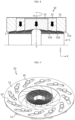
FIGS. 1 and2 are views showing an electrode assembly, in which forming of a foil tab is completed by a foil tab forming apparatus, and a current collection plate combined to the foil tab, according to an embodiment of the present disclosure. -
FIG. 3 is a view for describing an operation of a pre-forming jig configuring a foil tab forming apparatus, according to an embodiment of the disclosure. -
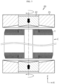
FIG. 4 is a view showing a forming jig configuring a foil tab forming apparatus, according to an embodiment of the disclosure. -
FIG. 5 is a view for describing an operation of a second pressing block included in the forming jig shown inFIG. 4 . -
FIG. 6 is a view for describing primary pressing performed by the forming jig shown inFIG. 4 . -
FIG. 7 is a view for describing secondary pressing performed by the forming jig shown inFIG. 4 . -
FIG. 8 is a view for describing a forming process by a forming jig configuring a foil tab forming apparatus, according to another embodiment of the present disclosure. -
FIGS. 9 and10 are views showing exemplary forms of the forming jig of the present disclosure. -
FIG. 11 is a view showing an orientation form of the foil tab formed by the forming jig of the present disclosure rotating in a counterclockwise direction. - Hereinafter, preferred embodiments of the present disclosure will be described in detail with reference to the accompanying drawings. Prior to the description, it should be understood that the terms used in the specification and the appended claims should not be construed as limited to general and dictionary meanings, but interpreted based on the meanings and concepts corresponding to technical aspects of the present disclosure on the basis of the principle that the inventor is allowed to define terms appropriately for the best explanation. Therefore, the description proposed herein is just a preferable example for the purpose of illustrations only, not intended to limit the scope of the disclosure, so it should be understood that other equivalents and modifications could be made thereto without departing from the scope of the disclosure.
- A foil tab forming apparatus of the present disclosure is an apparatus configured such that at least one foil tab of a positive electrode foil tab and a negative electrode foil tab provided respectively at a top portion and a bottom portion of a jelly-roll type electrode assembly is easily formed.
- Referring to
FIGS. 1 and2 , a structure of a foil tab T formed by the foil tab forming apparatus of the present disclosure is illustrated. The foil tab T refers to a first electrode uncoated portion extending upward along a direction parallel to a winding axis of an electrode assembly C (a direction parallel to a Z-axis ofFIG. 1 ) and/or a second electrode uncoated portion extending downward (the direction parallel to the Z-axis ofFIG. 1 ). The electrode assembly C has a structure in which a stack including a first electrode, a second electrode, and a separation film interposed between the first electrode and the second electrode is wound based on the winding axis. In the present specification, an example in which the first electrode is a positive electrode and the second electrode is a negative electrode will be described. The positive electrode includes a positive electrode uncoated portion formed in an end portion at one side in a width direction based on the stack before winding, and the negative electrode includes a negative electrode uncoated portion formed in an end portion at another side in the width direction based on the stack before winding. When the stack including the positive electrode and the negative electrode is wound to form the electrode assembly C, the positive electrode uncoated portion (a positive electrode active material uncoated region) is provided at an upper end portion of the electrode assembly C and the negative electrode uncoated portion (a negative electrode active material uncoated region) is provided at a lower end portion thereof. - An aluminum foil may be used as an electrode plate constituting the positive electrode, and a copper foil may be used as an electrode plate constituting the negative electrode. Thus, in the present specification, the positive electrode uncoated portion and the negative electrode uncoated portion will be each referred to as the foil tab T. The positive electrode foil tab and the negative electrode foil tab have shapes extending upward and downward of the electrode assembly C, respectively, i.e., shapes extending in opposite directions.
- A current collection plate P is combined to the foil tab T. In order to improve a combining force between the current collection plate P and the foil tab T and reduce electric resistance at a combining portion, it is necessary to form a combining interface as flat as possible to widen a combining area between the foil tab T and the current collection plate P as much as possible. In this regard, the foil tab T may be bent such that an end portion of the foil tab T extends in a direction parallel to the current collection plate P. For smoothness of the bending, one foil tab continuously formed from a winding center portion to an outermost side of the electrode assembly may be, for example, notched as shown in
FIG. 2 to a plurality of segments and then bend the foil tab. - The foil tab forming apparatus of the present disclosure is characterized in that the foil tab is configured to be smoothly and uniformly bent throughout a region from the outer circumferential portion of the electrode assembly C to the winding center portion.
- Referring to
FIGS. 3 and4 , the foil tab forming apparatus is an apparatus for forming the at least one foil tab T of the positive electrode foil tab and the negative electrode foil tab respectively provided at the top portion and the bottom portion of the electrode assembly C. The foil tab forming apparatus may include a formingjig 20 configured to form the foil tab T, and may further include apre-forming jig 10 configured to perform pre-forming before the foil tab T is formed by the formingjig 20. In this specification, the foil tab forming apparatus of the present disclosure is described on the premise that it includes both thepre-forming jig 10 and the formingjig 20, but unlike this, the foil tab forming apparatus of the present disclosure may also be configured not to include thepre-forming jig 10. Even in this case, as explained later, the formingjig 20 of the present disclosure may be configured to perform intensive forming with a time interval for each area of the foil tab T, so that uniform and accurate forming may be performed over the entire area of the foil tab T. - Referring to
FIG. 3 , thepre-forming jig 10 is configured to press and bend the foil tab T while moving in a direction from the outer circumferential portion of the electrode assembly C to the winding center portion of the electrode assembly C. Thepre-forming jig 10 may be provided as a pair ofpre-forming jigs 10 respectively disposed at both opposite ends of the electrode assembly C along the winding axis of the electrode assembly C. Thepre-forming jig 10 may include a plurality of shutter blocks 11. The plurality of shutter blocks 11 are disposed along a circumference of the outer circumferential portion of the electrode assembly and configured to bend the foil tab T while moving along a direction facing the winding center portion of the electrode assembly C. Theshutter block 11 may have a surface facing the foil tab T, the surface having an upward inclined shape along the direction from the outer circumferential portion of the electrode assembly C to the winding center portion of the electrode assembly C. That is, eachshutter block 11 may have a surface inclined upward such that the thickness of theshutter block 11 decreases from the outside to the inside. - Referring to
FIGS. 4 and5 together withFIG. 3 , the formingjig 20 is configured to press the foil tab T that has been completely pre-formed by thepre-forming jig 10, by moving along a direction parallel to the winding axis of the electrode assembly C. The formingjig 20 may have, for example, a shape approximately similar to a cylinder. The formingjig 20 may be provided as a pair of forming jigs respectively disposed at both opposite ends of the electrode assembly C along the winding axis of the electrode assembly C. - The forming
jig 20 may have a width equal to or greater than a diameter of the electrode assembly C. This is to form all of an entire region of the foil tab T during the pressing performed by using the formingjig 20. The formingjig 20 may be configured to rotate based on the same axis as the winding axis of the electrode assembly C. If the formingjig 20 is provided in a pair and respectively provided at both ends of the electrode assembly C in the height direction (parallel to the Z-axis), the pair of formingjigs 20 may rotate in opposite directions. The formingjig 20 may be configured to simultaneously perform an operation of pressing the foil tab T and an operation of rotating. When the pressing and rotation are performed together, more smooth and natural bending is possible. If the rotation direction of the formingjig 20 is a clockwise direction, the foil tab T may be oriented in the clockwise direction (seeFIG. 2 ). Conversely, if the rotation direction of the formingjig 20 is a counterclockwise direction, the foil tab T may be oriented in the counterclockwise direction (seeFIG. 11 ). - The forming
jig 20 may have a surface facing the foil tab T, the surface having an upward inclined shape along the direction from the outer circumferential portion of the electrode assembly C to the winding center portion. That is, the formingjig 20 may have a surface inclined upward so that the thickness of the formingjig 20 decreases from the outside to the center. According to such a structure of the formingjig 20, a phenomenon, in which the electrode assembly C is damaged due to excessive force applied to the foil tab T when the foil tab T is pressed, may be prevented, and natural bending may be achieved. - The forming
jig 20 may include a firstpressing block 21 and a secondpressing block 22. The firstpressing block 21 is provided at a location corresponding to a first region of the foil tab T, the first region being relatively adjacent to the outer circumferential portion of the electrode assembly C. The secondpressing block 22 is provided at a location corresponding to a second region of the foil tab T, the second region being relatively adjacent to the winding center of the electrode assembly C. For example, when the formingjig 20 has a shape approximately similar to a cylinder, the firstpressing block 21 may have a shape similar to a cylinder having an empty center portion, and the secondpressing block 22 may be disposed in the empty center portion of the firstpressing block 21. - A pressing surface of the first
pressing block 21 and a pressing surface of the secondpressing block 22 may have an approximately same inclination. In this case, the pressing surface of the firstpressing block 21 and the pressing surface of the secondpressing block 22 may form an approximately same plane. That is, the pressing surface of the firstpressing block 21 and the pressing surface of the secondpressing block 22 may be connected to each other to define a surface of the formingjig 20 facing the foil tab T. - The first
pressing block 21 and the secondpressing block 22 may be configured to be independently movable along a direction parallel to the winding axis of the electrode assembly C (a direction parallel to the Z-axis). For example, as shown inFIG. 5 , the secondpressing block 22 may additionally move in a direction facing the foil tab T while the firstpressing block 21 is stopped. - Referring to
FIGS. 6 and 7 , the formingjig 20 may be configured such that firstpressing block 21 and the secondpressing block 22 perform the primary pressing by moving towards the foil tab T together, while the pressing surface of the firstpressing block 21 and the pressing surface of the secondpressing block 22 form the same plane. Also, the formingjig 20 may be configured such that the secondpressing block 22 performs the secondary pressing by further moving towards the foil tab T while a location of the firstpressing block 21 is maintained, after the primary pressing is performed. As such, when the formingjig 20 includes the plurality of pressingblocks pressing block 22 located closer to the center portion, more elaborate forming may be achieved. Due to an inclined direction of the pressing surface of the formingjig 20, a bending point of the foil tab T moves towards an end portion of the foil tab T in a direction from the outer circumferential portion of the electrode assembly C to the winding center portion, during the pressing. Accordingly, when the additional pressing is performed by using the secondpressing block 22, a deviation of such a bending point may be reduced. - Meanwhile, the forming
jig 20 may be configured such that, after the primary pressing and the secondary pressing are completed, alowest portion 22a of the secondpressing block 22 is located at a height equal to or higher than alowest portion 21a of the firstpressing block 21. This is because, when the pressing by the secondpressing block 22 is excessively deeply performed, a bending location deviation at a boundary point between the firstpressing block 21 and the secondpressing block 22 may become too big. - The first
pressing block 21 and the secondpressing block 22 may be configured to rotate independently or together based on the same axis as the winding axis of the electrode assembly C. In other words, the firstpressing block 21 and the secondpressing block 22 may be connected to one driving means and rotate together, or may be connected to separate driving means respectively and rotate independently. - The first
pressing block 21 and the secondpressing block 22 may move towards the foil tab T while the pressing surfaces thereof form an approximately same plane to bend the foil tab T (primary forming) through pressing and rotation, and then perform additional bending (secondary forming) through additional pressing and rotation, by using the secondpressing block 22 while a rotation state of the firstpressing block 21 is maintained. The first region of the foil tab T may be intensively formed by the primary forming. Of course, while the first region is intensively formed, the second region may also be formed together. In addition, the second region of the foil tab T may be intensively formed by the secondary forming. While the second region is intensively formed, the first region may also be continuously formed. - Whether or not the remaining region is continuously formed while any one of the first region and the second region is intensively formed may be determined according to the location of the forming
jig 20 in the vertical direction (direction parallel to the Z-axis). - Meanwhile, referring to
FIG. 8 , unlike the formingjig 20 shown inFIGS. 4 through 7 , a formingjig 30 including threepressing blocks pressing blocks jig - The first
pressing block 31 may be provided at a location corresponding to a first region of the foil tab T, the first region being relatively adjacent to the outer circumferential portion of the electrode assembly C. The thirdpressing block 33 may be provided at a location corresponding to a third region of the foil tab T, the third region being adjacent to the core side, namely the winding center portion, of the electrode assembly C. The secondpressing block 32 may be provided at a location corresponding to a second region of the foil tab T, the second region being located between the first region and the third region. The pressing surfaces of the firstpressing block 31, the secondpressing block 32 and the thirdpressing block 33 may have approximately the same inclination. Accordingly, the inclined surfaces of the firstpressing block 31, the secondpressing block 32 and the thirdpressing block 33 may define a surface of the formingjig 30 facing the foil tab T. - As shown in
FIG. 8 , when the formingjig 30 includes a firstpressing block 31, a secondpressing block 32, and a thirdpressing block 33, the threepressing blocks pressing block 32 and the thirdpressing block 33 may similarly perform pressing and rotation by additionally moving while maintaining a state in which the pressing surfaces thereof form the approximately same plane, thereby forming the foil tab T (secondary forming). The second region of the foil tab T may be intensively formed by the secondary forming. Here, a rotating state of the firstpressing block 31 may be continuously maintained, and thus the first region and the third region may also be continuously formed while the second region is intensively formed. The thirdpressing block 33 may perform pressing and rotation by additionally moving after the additional pressing is performed by the secondpressing block 32, thereby forming the foil tab T (tertiary forming). The third region of the foil tab T may be intensively formed by the tertiary forming. At this time, rotating states of the firstpressing block 31 and the secondpressing block 32 may be continuously maintained, and thus the first region and the second region may also be continuously formed while the third region is intensively formed. - Whether or not the remaining regions are continuously formed while any one of the first region, the second region and the third region is intensively formed may be determined according to the location of the forming
jig 20 in the vertical direction (direction parallel to the Z-axis). - Referring to
FIGS. 3 ,9 and10 , an exemplary form of thepre-forming jig 10 is shown. Thepre-forming jig 10 may include, for example, ashutter frame 12 having a plurality ofslots 14. Eachshutter block 11 may be supported by aguide member 16 extending through theslot 14, inside the correspondingslot 14. Theguide member 16 may move inside theslot 14 as theshutter frame 12 rotates based on an axis parallel to the winding axis of the electrode assembly C. Theslot 14 may have a curved shape so that theshutter block 11 may easily move toward and away from the winding axis of the electrode assembly C. The overall movement of theshutter block 11 may be similar to, for example, opening and closing of the iris. That is, theshutter block 11 may be coupled to theshutter frame 12 and configured to perform a closing operation for moving toward the electrode assembly C and an opening operation for moving away from electrode assembly C, which is disposed in an empty space formed at the center of theshutter frame 12. Meanwhile, theshutter block 11 may be opened/closed by rotation of theshutter frame 12, or may be opened/closed by moving theguide member 16 in the extending direction of theslot 14. - Next, a foil tab forming method of the present disclosure will be described. The foil tab forming method of the present disclosure is a method of forming the foil tab T of the electrode assembly C by using the foil tab forming apparatus of the present disclosure described above.
- Referring to
FIGS. 3 through 8 that have been referred to above, the foil tab forming method of the present disclosure is a method of forming the at least one foil tab T of the positive electrode foil tab and the negative electrode foil tab respectively provided at the top portion and the bottom portion of the electrode assembly C. - The foil tab forming method is a method of forming a foil tab T of an electrode assembly C having an outer circumferential portion and a winding center portion defining a winding axis, and includes the step of (S 1) bending the foil tab T by pressing the foil tab T along a direction parallel to the winding axis of the electrode assembly C by using a forming
jig 20. The foil tab forming method may further include the step of (S0) bending the foil tab T by pressing the foil tab T in a direction from the outer circumferential portion of the electrode assembly C toward the winding center portion of the electrode assembly C by using apre-forming jig 10 prior to the step (S1). In this case, the step (S1) may be a step of additionally bending the foil tab T by pressing the foil tab T that has been pre-formed according to the step (S0). - The step (S0) may be performed by using the
pre-forming jig 10 including a plurality of shutter blocks 11 disposed along a circumference of the outer circumferential portion of the electrode assembly C and bending the foil tab T by moving along a direction toward the winding center portion of the electrode assembly C. The step (S0) may be performed by using thepre-forming jig 10 having a plurality of shutter blocks 11 having a surface facing the foil tab T, the surface being inclined upward in a direction from the outer circumferential portion of the electrode assembly C toward the winding center portion. The step (S0) may be performed by using a pair ofpre-forming jigs 10 disposed at both opposite ends of the electrode assembly C along the winding axis of the electrode assembly C. That is, the step (S0) may be a step of pre-forming each of the first foil tab (first polarity) and the second foil tab (second polarity) provided at both ends of the electrode assembly C in the height direction (parallel to the Z-axis). The pre-forming for the first foil tab and the pre-forming for the second foil tab may be performed at the same time or with a time interval. - The step (S1) may be performed by using the forming
jig 20 having the width equal to or greater than the diameter of the electrode assembly C. The step (S1) may be performed by using the formingjig 20 configured to rotate based on the same axis as the winding axis of the electrode assembly C. The step (S1) may be performed by using the formingjig 20 configured such that an operation of pressing the foil tab T and an operation of rotating may be performed together. In the step (S1), the formingjig 20 may rotate in a clockwise direction so that the foil tab T is oriented in the clockwise direction. Alternatively, in the step (S1), the formingjig 20 may rotate in a counterclockwise direction so that the rotating foil tab T is oriented in the counterclockwise direction. - The step (S1) may be performed by using the forming
jig 20 having the surface facing the foil tab T, the surface having the upward inclined shape along the direction from the outer circumferential portion of the electrode assembly C to the winding center portion. The step (S1) may be performed by using the formingjig 20 including the firstpressing block 21 provided at the location corresponding to the first region of the foil tab T, the first region being relatively adjacent to the outer circumferential portion of the electrode assembly C, and the secondpressing block 22 provided at the location corresponding to the second region of the foil tab T, the second region being relatively adjacent to the winding center of the electrode assembly C. - The step (S1) may be performed by the forming
jig 20 in which the pressing surface of the firstpressing block 21 and the pressing surface of the secondpressing block 22 have the same inclination. The step (S1) may be performed by the formingjig 20 configured such that the firstpressing block 21 and the secondpressing block 22 are independently movable along the direction parallel to the winding axis of the electrode assembly C. - The step (S1) may include steps of: (S1 1) performing the primary pressing as the first
pressing block 21 and the secondpressing block 22 move towards the foil tab together while the pressing surface of the firstpressing block 21 and the pressing surface of the secondpressing block 22 form the same plane; and (S12) performing the secondary pressing as the secondpressing block 22 further moves towards the foil tab T while the location of the firstpressing block 21 is maintained, after the step (S11) is performed. Here, thelowest portion 22a of the second pressing block after the steps (S11) and (S12) are performed may be located at a height equal to or higher than thelowest portion 21a of the firstpressing block 21. The step (S1) may be performed as the firstpressing block 21 and the secondpressing block 22 rotate independently or together based on the same axis as the winding axis. - Meanwhile, the step (S1) may be performed by the forming
jig 30 including a firstpressing block 31 provided at a location corresponding to a first region of the foil tab T, the first region being relatively adjacent to the outer circumferential portion of the electrode assembly C, a thirdpressing block 33 may be provided at a location corresponding to a third region of the foil tab T, the third region being relatively adjacent to the winding center portion of the electrode assembly C, and a secondpressing block 32 provided at a location corresponding to a second region of the foil tab T, the second region being located between the first region and the third region. The step (S1) may be performed by the formingjig 20 in which the pressing surface of the firstpressing block 31, the pressing surface of the secondpressing block 32, and the pressing surface of the thirdpressing block 33 have approximately the same inclination. In this case, the step (S1) may include the steps of (S11) performing primary pressing as the firstpressing block 31, the secondpressing block 32 and the thirdpressing block 33 move together towards the foil tab T while the pressing surface of the firstpressing block 31, the pressing surface of the secondpressing block 32 and the pressing surface of the thirdpressing block 33 form the same plane; (S12) after the step (S11) is performed, performing secondary pressing as the secondpressing block 32 and the thirdpressing block 33 move towards the foil tab T while the pressing surface of the secondpressing block 32 and the pressing surface of the thirdpressing block 33 form the same plane and a location of the firstpressing block 31 is maintained; and (S13) after the step (S12) is performed, performing tertiary pressing as the thirdpressing block 33 moves towards the foil tab T while a location of the firstpressing block 31 and a location of the secondpressing block 32 are maintained. The step (S1) may be performed by using a pair of formingjigs 20 disposed at both opposite ends of the electrode assembly C along the winding axis of the electrode assembly C. That is, the step (S1) may be a step of forming each of the first foil tab (first polarity) and the second foil tab (second polarity) provided at both ends of the electrode assembly C in the height direction (parallel to the Z-axis). In this case, the step (S1) may be performed by rotating the pair of formingjigs 20 in opposite directions based on the same axis as the winding axis of the electrode assembly C. The forming for the first foil tab and the forming for the second foil tab can be made at the same time or with a time interval. - As described above, according to the foil tab forming apparatus of the present disclosure and/or the foil tab forming method of the present disclosure, by dividing the foil tab T of the electrode assembly C into a plurality of regions along the approximately radial direction of the electrode assembly C and enabling each region to be intensive formed individually, efficient and accurate forming is possible. Moreover, according to the foil tab forming apparatus of the present disclosure and/or the foil tab forming method of the present disclosure, a method in which rotation and pressurization are made simultaneously may be applied, and thus forming may be performed more smoothly.
- The present disclosure has been described in detail. However, it should be understood that the detailed description and specific examples, while indicating preferred embodiments of the disclosure, are given by way of illustration only, since various changes and modifications within the scope of the disclosure will become apparent to those skilled in the art from this detailed description.
-
- C: electrode assembly
- T: foil tab
- P: current collection plate
- 10: pre-forming jig
- 11: shutter block
- 12: shutter frame
- 14: slot
- 16: guide member
- 20, 30: forming jig
- 21, 31: first pressing block
- 22, 32: second pressing block
- 33: third pressing block
Claims (41)
- A foil tab forming apparatus for forming a foil tab of an electrode assembly that includes an outer circumferential portion and a winding center portion defining a winding axis, the foil tab forming apparatus comprising:
a forming jig configured to press the foil tab by moving along a direction parallel to the winding axis of the electrode assembly. - The foil tab forming apparatus of claim 1, further comprising a pre-forming jig configured to bend the foil tab by pressing the foil tab, while moving in a direction from the outer circumferential portion of the electrode assembly to the winding center portion of the electrode assembly,
wherein the forming jig is configured to press the foil tab that has been primarily bent by the pre-forming jig. - The foil tab forming apparatus of claim 2, wherein the pre-forming jig comprises a plurality of shutter blocks disposed along a circumference of the outer circumferential portion of the electrode assembly and bending the foil tab by moving along a direction facing the winding center portion of the electrode assembly.
- The foil tab forming apparatus of claim 3, wherein the shutter block has a surface facing the foil tab, the surface having an upward inclined shape along a direction from the outer circumferential portion of the electrode assembly to the winding center portion.
- The foil tab forming apparatus of claim 1, wherein the forming jig has a width equal to or greater than a diameter of the electrode assembly.
- The foil tab forming apparatus of claim 1, wherein the forming jig is configured to rotate based on the same axis as the winding axis of the electrode assembly.
- The foil tab forming apparatus of claim 6, wherein the forming jig is configured to rotate in a clockwise direction or in a counterclockwise direction.
- The foil tab forming apparatus of claim 6, wherein the forming jig is configured to simultaneously perform an operation of pressing the foil tab and an operation of rotating.
- The foil tab forming apparatus of claim 1, wherein the forming jig has a surface facing the foil tab, the surface having an upward inclined shape along a direction from the outer circumferential portion of the electrode assembly to the winding center portion.
- The foil tab forming apparatus of claim 9, wherein the forming jig comprises:a first pressing block provided at a location corresponding to a first region of the foil tab, the first region being relatively adjacent to the outer circumferential portion of the electrode assembly; anda second pressing block provided at a location corresponding to a second region of the foil tab, the second region being relatively adjacent to the winding center of the electrode assembly.
- The foil tab forming apparatus of claim 10, wherein a pressing surface of the first pressing block and a pressing surface of the second pressing block have the same inclination and define a surface of the forming jig facing the foil tab.
- The foil tab forming apparatus of claim 10, wherein the first pressing block and the second pressing block are configured to be independently movable along a direction parallel to the winding axis of the electrode assembly.
- The foil tab forming apparatus of claim 11, wherein the forming jig is configured to perform primary pressing as the first pressing block and the second pressing block move together towards the foil tab while the pressing surface of the first pressing block and the pressing surface of the second pressing block form the same plane, and then perform secondary pressing as the second pressing block moves further towards the foil tab while a location of the first pressing block is maintained.
- The foil tab forming apparatus of claim 13, wherein the forming jig is configured such that, after the primary pressing and the secondary pressing are completed, a lowest portion of the second pressing block is located at a height equal to or higher than a lowest portion of the first pressing block.
- The foil tab forming apparatus of claim 10, wherein the first pressing block and the second pressing block are configured to rotate independently or together based on the same axis as the winding axis.
- The foil tab forming apparatus of claim 9, wherein the forming jig comprises:a first pressing block provided at a location corresponding to a first region of the foil tab, the first region being relatively adjacent to the outer circumferential portion of the electrode assembly;a third pressing block provided at a location corresponding to a third region of the foil tab, the third region being relatively adjacent to the winding center portion of the electrode assembly; anda second pressing block provided at a location corresponding to a second region of the foil tab, the second region being located between the first region and the third region.
- The foil tab forming apparatus of claim 1, wherein the forming jig is provided as a pair of forming jigs disposed at both opposite ends of the electrode assembly along the winding axis of the electrode assembly.
- The foil tab forming apparatus of claim 17, wherein the pair of forming jigs rotate in opposite directions based on the same axis as the winding axis of the electrode assembly.
- The foil tab forming apparatus of claim 2, wherein the pre-forming jig is provided as a pair of pre-forming jigs disposed at both opposite ends of the electrode assembly along the winding axis of the electrode assembly.
- A foil tab forming method for forming a foil tab of an electrode assembly that includes an outer circumferential portion and a winding center portion defining a winding axis, the foil tab forming method comprising steps of:
(S1) bending the foil tab by pressing the foil tab along a direction parallel to the winding axis of the electrode assembly by using a forming jig. - The foil tab forming method of claim 20, further comprising:(S0) bending the foil tab by pressing the foil tab in a direction from the outer circumferential portion of the electrode assembly to the winding center portion of the electrode assembly by using a pre-forming jig, prior to the step (S1),wherein the step (S1) is a step of additionally bending the foil tab by pressing the foil tab that has been pre-formed according to the step (S0).
- The foil tab forming method of claim 21, wherein the step (S0) is performed by using the pre-forming jig including a plurality of shutter blocks disposed along a circumference of the outer circumferential portion of the electrode assembly and bending the foil tab by moving along a direction facing the winding center portion of the electrode assembly.
- The foil tab forming method of claim 22, wherein the step (S0) is performed by using the pre-forming jig including the plurality of shutter blocks having a surface facing the foil tab, the surface having an upward inclined shape along a direction from the outer circumferential portion of the electrode assembly to the winding center portion.
- The foil tab forming method of claim 20, wherein the step (S1) is performed by using the forming jig having a width equal to or greater than a diameter of the electrode assembly.
- The foil tab forming method of claim 20, wherein the step (S1) is performed by using the forming jig configured to rotate based on the same axis as the winding axis of the electrode assembly.
- The foil tab forming method of claim 20, wherein the step (S1) is performed by using the forming jig configured to simultaneously perform an operation of pressing the foil tab and an operation of rotating.
- The foil tab forming method of claim 26, wherein in the step (S1), the forming jig rotates in a clockwise direction so that the foil tab is oriented in the clockwise direction.
- The foil tab forming method of claim 26, wherein in the step (S1), the forming jig rotates in a counterclockwise direction so that the foil tab is oriented in the counterclockwise direction.
- The foil tab forming method of claim 20, wherein the step (S1) is performed by using the forming jig having a surface facing the foil tab, the surface having an upward inclined shape along a direction from the outer circumferential portion of the electrode assembly to the winding center portion.
- The foil tab forming method of claim 29, wherein the step (S1) is performed by using the forming jig comprising a first pressing block provided at a location corresponding to a first region of the foil tab, the first region being relatively adjacent to the outer circumferential portion of the electrode assembly, and a second pressing block provided at a location corresponding to a second region of the foil tab, the second region being relatively adjacent to the winding center of the electrode assembly.
- The foil tab forming method of claim 30, wherein the step (S1) is performed by using the forming jig in which a pressing surface of the first pressing block and a pressing surface of the second pressing block have the same inclination.
- The foil tab forming method of claim 30, wherein the step (S1) is performed by using the forming jig configured such that the first pressing block and the second pressing block are independently movable along a direction parallel to the winding axis of the electrode assembly.
- The foil tab forming method of claim 31, wherein the step (S1) comprises steps of:(S11) performing primary pressing as the first pressing block and the second pressing block move together towards the foil tab while the pressing surface of the first pressing block and the pressing surface of the second pressing block form the same plane; and(S12) after the step (S11) is performed, performing secondary pressing as the second pressing block further moves towards the foil tab while a location of the first pressing block is maintained.
- The foil tab forming method of claim 33, wherein after the step (S11) and the step (S12) are performed, a lowest portion of the second pressing block is located at a height equal to or higher than a lowest portion of the first pressing block.
- The foil tab forming method of claim 30, wherein the step (S1) is performed as the first pressing block and the second pressing block rotate together or independently based on the same axis as the winding axis.
- The foil tab forming method of claim 29, wherein the step (S1) is performed by using the forming jig comprising a first pressing block provided at a location corresponding to a first region of the foil tab, the first region being relatively adjacent to the outer circumferential portion of the electrode assembly, a third pressing block provided at a location corresponding to a third region of the foil tab, the third region being relatively adjacent to the winding center portion of the electrode assembly, and a second pressing block provided at a location corresponding to a second region of the foil tab, the second region being located between the first region and the third region.
- The foil tab forming method of claim 36, wherein the step (S1) is performed by using the forming jig in which a pressing surface of the first pressing block, a pressing surface of the second pressing block and a pressing surface of the third pressing block have the same inclination.
- The foil tab forming method of claim 37, wherein the step (S1) comprises steps of:(S 11) performing primary pressing as the first pressing block, the second pressing block and the third pressing block move together towards the foil tab while the pressing surface of the first pressing block, the pressing surface of the second pressing block and the pressing surface of the third pressing block form the same plane;(S12) after the step (S11) is performed, performing secondary pressing as the second pressing block and the third pressing block move towards the foil tab while the pressing surface of the second pressing block and the pressing surface of the third pressing block form the same plane and a location of the first pressing block is maintained; and(S13) after the step (S12) is performed, performing tertiary pressing as the third pressing block moves towards the foil tab while a location of the first pressing block and a location of the second pressing block are maintained.
- The foil tab forming method of claim 20, wherein the step (S1) is performed by using the forming jig provided as a pair of forming jigs disposed at both opposite ends of the electrode assembly along the winding axis of the electrode assembly.
- The foil tab forming method of claim 39, wherein the step (S1) is performed by rotating the pair of forming jigs in opposite directions based on the same axis as the winding axis of the electrode assembly.
- The foil tab forming method of claim 21, wherein the step (S0) is performed by using the pre-forming jig provided as a pair of pre-forming jigs disposed at both opposite ends of the electrode assembly along the winding axis of the electrode assembly.
Applications Claiming Priority (3)
| Application Number | Priority Date | Filing Date | Title |
|---|---|---|---|
| KR20210030278 | 2021-03-08 | ||
| KR1020210137853A KR20220126197A (en) | 2021-03-08 | 2021-10-15 | Apparatus for forming an foil tap and Method for forming an foil tap |
| PCT/KR2022/003284 WO2022191591A1 (en) | 2021-03-08 | 2022-03-08 | Foil tab forming apparatus and foil tab forming method |
Publications (3)
| Publication Number | Publication Date |
|---|---|
| EP4258455A1 true EP4258455A1 (en) | 2023-10-11 |
| EP4258455A4 EP4258455A4 (en) | 2024-12-04 |
| EP4258455B1 EP4258455B1 (en) | 2025-10-29 |
Family
ID=83157373
Family Applications (1)
| Application Number | Title | Priority Date | Filing Date |
|---|---|---|---|
| EP22767487.6A Active EP4258455B1 (en) | 2021-03-08 | 2022-03-08 | Foil tab forming apparatus and foil tab forming method |
Country Status (7)
| Country | Link |
|---|---|
| US (1) | US20240123481A1 (en) |
| EP (1) | EP4258455B1 (en) |
| JP (1) | JP7614368B2 (en) |
| KR (1) | KR102937227B1 (en) |
| CN (2) | CN115041588A (en) |
| ES (1) | ES3060473T3 (en) |
| WO (1) | WO2022191591A1 (en) |
Cited By (1)
| Publication number | Priority date | Publication date | Assignee | Title |
|---|---|---|---|---|
| IT202400002211A1 (en) * | 2024-02-02 | 2025-08-02 | Gd Spa | ELECTROCHEMICAL CELL PACKAGING APPARATUS FOR BATTERY PRODUCTION |
Families Citing this family (6)
| Publication number | Priority date | Publication date | Assignee | Title |
|---|---|---|---|---|
| EP4258455B1 (en) * | 2021-03-08 | 2025-10-29 | LG Energy Solution, Ltd. | Foil tab forming apparatus and foil tab forming method |
| JP7806235B2 (en) * | 2021-11-11 | 2026-01-26 | エルジー エナジー ソリューション リミテッド | Tab forming apparatus for jelly roll type electrode assembly and forming method using the same |
| DE102022117045A1 (en) * | 2022-07-08 | 2024-01-25 | Bayerische Motoren Werke Aktiengesellschaft | Method and processing device for producing a storage cell for an electrical energy storage device, in particular a motor vehicle, and use of a processing device |
| KR102875737B1 (en) * | 2023-03-02 | 2025-10-27 | 엘지전자 주식회사 | Forming apparatus |
| KR102634101B1 (en) * | 2023-10-17 | 2024-02-06 | (주)금양 | Cylindrical battery manufacturing apparatus and method |
| WO2026043134A1 (en) * | 2024-08-21 | 2026-02-26 | 주식회사 엘지에너지솔루션 | Secondary battery and method for manufacturing same |
Family Cites Families (16)
| Publication number | Priority date | Publication date | Assignee | Title |
|---|---|---|---|---|
| JP2529176B2 (en) * | 1982-12-15 | 1996-08-28 | 松下電器産業株式会社 | Battery spiral plate assembly device |
| JPH067494B2 (en) * | 1986-07-29 | 1994-01-26 | 新神戸電機株式会社 | Apparatus for manufacturing storage battery having spiral electrode group |
| US5972532A (en) * | 1998-05-04 | 1999-10-26 | Saft America, Inc. | Current collection through the ends of a spirally wound electrochemical cell |
| JP2001118562A (en) * | 1999-10-20 | 2001-04-27 | Sony Corp | Lead forming method |
| KR100599710B1 (en) | 2004-07-28 | 2006-07-12 | 삼성에스디아이 주식회사 | Secondary Battery, Electrode Assembly and Secondary Battery Manufacturing Method |
| JP5004452B2 (en) | 2005-03-31 | 2012-08-22 | 三洋電機株式会社 | Battery manufacturing method |
| JP5006603B2 (en) * | 2006-09-06 | 2012-08-22 | 株式会社日立製作所 | Nonaqueous electrolyte secondary battery |
| US20080254354A1 (en) * | 2007-04-11 | 2008-10-16 | Saft | Connection system for an electrochemical cell |
| FR2921195B1 (en) * | 2007-09-13 | 2009-11-06 | Batscap Sa | METHOD AND DEVICE FOR MANUFACTURING ELECTRIC ENERGY STORAGE CABINETS |
| CN201185204Y (en) * | 2008-03-19 | 2009-01-21 | 深圳市比克电池有限公司 | Apparatus for bending cathode ear of cylinder battery |
| CN103779528B (en) * | 2014-01-15 | 2015-12-02 | 合肥国轩高科动力能源股份公司 | A kind of column lithium ion battery assembly technology |
| CN104953190A (en) * | 2015-06-26 | 2015-09-30 | 张贵萍 | Cell winding body shaping method and equipment and high-capacity lithium ion battery and production method thereof |
| CN105406018B (en) * | 2015-11-04 | 2018-06-29 | 丹东思诚科技有限公司 | A kind of cylindrical battery core plate lug connecting method and pretreatment fixture |
| KR20250109799A (en) | 2018-07-11 | 2025-07-17 | 가부시키가이샤 한도오따이 에네루기 켄큐쇼 | Light-emitting device, display device, electronic device, organic compound, and lighting device |
| KR102403908B1 (en) | 2020-05-11 | 2022-05-31 | 주식회사 상남 | Carbon fiber heating element and electric boiler comprising the same |
| EP4258455B1 (en) * | 2021-03-08 | 2025-10-29 | LG Energy Solution, Ltd. | Foil tab forming apparatus and foil tab forming method |
-
2022
- 2022-03-08 EP EP22767487.6A patent/EP4258455B1/en active Active
- 2022-03-08 JP JP2023540035A patent/JP7614368B2/en active Active
- 2022-03-08 CN CN202210227343.6A patent/CN115041588A/en active Pending
- 2022-03-08 KR KR1020220029319A patent/KR102937227B1/en active Active
- 2022-03-08 US US18/278,123 patent/US20240123481A1/en active Pending
- 2022-03-08 WO PCT/KR2022/003284 patent/WO2022191591A1/en not_active Ceased
- 2022-03-08 CN CN202220504819.1U patent/CN217570440U/en active Active
- 2022-03-08 ES ES22767487T patent/ES3060473T3/en active Active
Cited By (2)
| Publication number | Priority date | Publication date | Assignee | Title |
|---|---|---|---|---|
| IT202400002211A1 (en) * | 2024-02-02 | 2025-08-02 | Gd Spa | ELECTROCHEMICAL CELL PACKAGING APPARATUS FOR BATTERY PRODUCTION |
| WO2025163548A1 (en) * | 2024-02-02 | 2025-08-07 | G.D S.P.A. | Apparatus for packaging electrochemical cells for the production of batteries |
Also Published As
| Publication number | Publication date |
|---|---|
| JP2024502425A (en) | 2024-01-19 |
| EP4258455B1 (en) | 2025-10-29 |
| JP7614368B2 (en) | 2025-01-15 |
| KR20220126246A (en) | 2022-09-15 |
| ES3060473T3 (en) | 2026-03-26 |
| US20240123481A1 (en) | 2024-04-18 |
| KR102937227B1 (en) | 2026-03-10 |
| EP4258455A4 (en) | 2024-12-04 |
| CN115041588A (en) | 2022-09-13 |
| WO2022191591A1 (en) | 2022-09-15 |
| CN217570440U (en) | 2022-10-14 |
Similar Documents
| Publication | Publication Date | Title |
|---|---|---|
| EP4258455A1 (en) | Foil tab forming apparatus and foil tab forming method | |
| CN113678294B (en) | Secondary battery | |
| US9209478B2 (en) | Elongated mandrel for a winding device | |
| KR100421350B1 (en) | Spiral electrode group winding method and device and battery using them | |
| EP4087034A1 (en) | Apparatus and method for producing cylindrical secondary battery cell | |
| KR102499324B1 (en) | Rolling Device for Secondary Battery | |
| EP4498505A1 (en) | Full-tab negative electrode sheet and cylindrical battery | |
| RU2453011C2 (en) | Manufacturing method of electric energy accumulators, and device for its implementation | |
| KR20190116813A (en) | The Unloading Gripper For The Secondary Battery And The Apparatus For Folding The Secondary Battery | |
| KR102803275B1 (en) | Electrode notching equipment for rechargeable battery, electrode manufactured from thereof and rechargeable battery | |
| EP4395018A1 (en) | Necking method, necking device and battery manufacturing apparatus | |
| KR102444997B1 (en) | Electrode assembly, secondary battery equipped with it and method for manufacturing thereof | |
| KR20220122400A (en) | Fixing device for cylindrical electrode assembly | |
| EP4293770A1 (en) | Method for assemblying battery assembly, battery assembly, and secondary battery comprising same | |
| KR102702689B1 (en) | Battery cell folding gripper and battery cell folding device | |
| KR20220126197A (en) | Apparatus for forming an foil tap and Method for forming an foil tap | |
| JP2025534527A (en) | electrode assembly | |
| KR102634476B1 (en) | Lead Tab Forming System for Cylindrical Secondary Battery | |
| EP4597617A1 (en) | Automatic electrode plate reading apparatus for secondary batteries | |
| CN223378209U (en) | Diaphragm winding device | |
| US20250055089A1 (en) | Secondary battery and manufacturing method thereof | |
| EP4583218B1 (en) | Mandrel member of winder for secondary battery | |
| US20260018645A1 (en) | Crimping apparatus and method for cylindrical secondary cells | |
| EP4629374A2 (en) | Secondary battery manufacturing apparatus and secondary battery manufactured using the secondary battery manufacturing apparatus | |
| US20250128311A1 (en) | Blanking device and method of manufacturing electrode plate for secondary battery using the same |
Legal Events
| Date | Code | Title | Description |
|---|---|---|---|
| STAA | Information on the status of an ep patent application or granted ep patent |
Free format text: STATUS: THE INTERNATIONAL PUBLICATION HAS BEEN MADE |
|
| PUAI | Public reference made under article 153(3) epc to a published international application that has entered the european phase |
Free format text: ORIGINAL CODE: 0009012 |
|
| STAA | Information on the status of an ep patent application or granted ep patent |
Free format text: STATUS: REQUEST FOR EXAMINATION WAS MADE |
|
| 17P | Request for examination filed |
Effective date: 20230706 |
|
| AK | Designated contracting states |
Kind code of ref document: A1 Designated state(s): AL AT BE BG CH CY CZ DE DK EE ES FI FR GB GR HR HU IE IS IT LI LT LU LV MC MK MT NL NO PL PT RO RS SE SI SK SM TR |
|
| DAV | Request for validation of the european patent (deleted) | ||
| DAX | Request for extension of the european patent (deleted) | ||
| A4 | Supplementary search report drawn up and despatched |
Effective date: 20241031 |
|
| RIC1 | Information provided on ipc code assigned before grant |
Ipc: H01M 50/531 20210101ALI20241025BHEP Ipc: H01M 50/533 20210101ALI20241025BHEP Ipc: B21D 11/20 20060101ALI20241025BHEP Ipc: B21D 11/10 20060101ALI20241025BHEP Ipc: H01M 10/04 20060101ALI20241025BHEP Ipc: H01M 50/538 20210101AFI20241025BHEP |
|
| GRAP | Despatch of communication of intention to grant a patent |
Free format text: ORIGINAL CODE: EPIDOSNIGR1 |
|
| STAA | Information on the status of an ep patent application or granted ep patent |
Free format text: STATUS: GRANT OF PATENT IS INTENDED |
|
| RIC1 | Information provided on ipc code assigned before grant |
Ipc: H01M 50/538 20210101AFI20250625BHEP Ipc: H01M 10/04 20060101ALI20250625BHEP Ipc: B21D 11/10 20060101ALI20250625BHEP Ipc: B21D 11/20 20060101ALI20250625BHEP Ipc: H01M 50/533 20210101ALI20250625BHEP Ipc: H01M 50/531 20210101ALI20250625BHEP |
|
| INTG | Intention to grant announced |
Effective date: 20250728 |
|
| GRAS | Grant fee paid |
Free format text: ORIGINAL CODE: EPIDOSNIGR3 |
|
| GRAA | (expected) grant |
Free format text: ORIGINAL CODE: 0009210 |
|
| STAA | Information on the status of an ep patent application or granted ep patent |
Free format text: STATUS: THE PATENT HAS BEEN GRANTED |
|
| AK | Designated contracting states |
Kind code of ref document: B1 Designated state(s): AL AT BE BG CH CY CZ DE DK EE ES FI FR GB GR HR HU IE IS IT LI LT LU LV MC MK MT NL NO PL PT RO RS SE SI SK SM TR |
|
| REG | Reference to a national code |
Ref country code: CH Ref legal event code: F10 Free format text: ST27 STATUS EVENT CODE: U-0-0-F10-F00 (AS PROVIDED BY THE NATIONAL OFFICE) Effective date: 20251029 Ref country code: GB Ref legal event code: FG4D |
|
| REG | Reference to a national code |
Ref country code: IE Ref legal event code: FG4D |
|
| REG | Reference to a national code |
Ref country code: DE Ref legal event code: R096 Ref document number: 602022023993 Country of ref document: DE |
|
| P01 | Opt-out of the competence of the unified patent court (upc) registered |
Free format text: CASE NUMBER: UPC_APP_0012776_4258455/2025 Effective date: 20251110 |
|
| REG | Reference to a national code |
Ref country code: NL Ref legal event code: MP Effective date: 20251029 |
|
| REG | Reference to a national code |
Ref country code: ES Ref legal event code: FG2A Ref document number: 3060473 Country of ref document: ES Kind code of ref document: T3 Effective date: 20260326 |
|
| PGFP | Annual fee paid to national office [announced via postgrant information from national office to epo] |
Ref country code: GB Payment date: 20260224 Year of fee payment: 5 |
|
| REG | Reference to a national code |
Ref country code: LT Ref legal event code: MG9D |
|
| PG25 | Lapsed in a contracting state [announced via postgrant information from national office to epo] |
Ref country code: NO Free format text: LAPSE BECAUSE OF FAILURE TO SUBMIT A TRANSLATION OF THE DESCRIPTION OR TO PAY THE FEE WITHIN THE PRESCRIBED TIME-LIMIT Effective date: 20260129 |
|
| PGFP | Annual fee paid to national office [announced via postgrant information from national office to epo] |
Ref country code: DE Payment date: 20260220 Year of fee payment: 5 |
|
| PG25 | Lapsed in a contracting state [announced via postgrant information from national office to epo] |
Ref country code: AT Free format text: LAPSE BECAUSE OF FAILURE TO SUBMIT A TRANSLATION OF THE DESCRIPTION OR TO PAY THE FEE WITHIN THE PRESCRIBED TIME-LIMIT Effective date: 20251029 Ref country code: HR Free format text: LAPSE BECAUSE OF FAILURE TO SUBMIT A TRANSLATION OF THE DESCRIPTION OR TO PAY THE FEE WITHIN THE PRESCRIBED TIME-LIMIT Effective date: 20251029 Ref country code: FI Free format text: LAPSE BECAUSE OF FAILURE TO SUBMIT A TRANSLATION OF THE DESCRIPTION OR TO PAY THE FEE WITHIN THE PRESCRIBED TIME-LIMIT Effective date: 20251029 |
|
| PGFP | Annual fee paid to national office [announced via postgrant information from national office to epo] |
Ref country code: AT Payment date: 20260301 Year of fee payment: 5 |
|
| PGFP | Annual fee paid to national office [announced via postgrant information from national office to epo] |
Ref country code: BE Payment date: 20260220 Year of fee payment: 5 |
|
| REG | Reference to a national code |
Ref country code: AT Ref legal event code: MK05 Ref document number: 1852735 Country of ref document: AT Kind code of ref document: T Effective date: 20251029 |
|
| PG25 | Lapsed in a contracting state [announced via postgrant information from national office to epo] |
Ref country code: NL Free format text: LAPSE BECAUSE OF FAILURE TO SUBMIT A TRANSLATION OF THE DESCRIPTION OR TO PAY THE FEE WITHIN THE PRESCRIBED TIME-LIMIT Effective date: 20251029 |
|
| PGFP | Annual fee paid to national office [announced via postgrant information from national office to epo] |
Ref country code: HU Payment date: 20260310 Year of fee payment: 5 |
|
| PG25 | Lapsed in a contracting state [announced via postgrant information from national office to epo] |
Ref country code: RS Free format text: LAPSE BECAUSE OF FAILURE TO SUBMIT A TRANSLATION OF THE DESCRIPTION OR TO PAY THE FEE WITHIN THE PRESCRIBED TIME-LIMIT Effective date: 20260129 |
|
| PG25 | Lapsed in a contracting state [announced via postgrant information from national office to epo] |
Ref country code: IS Free format text: LAPSE BECAUSE OF FAILURE TO SUBMIT A TRANSLATION OF THE DESCRIPTION OR TO PAY THE FEE WITHIN THE PRESCRIBED TIME-LIMIT Effective date: 20260228 |
|
| PGFP | Annual fee paid to national office [announced via postgrant information from national office to epo] |
Ref country code: FR Payment date: 20260224 Year of fee payment: 5 |
|
| PG25 | Lapsed in a contracting state [announced via postgrant information from national office to epo] |
Ref country code: PT Free format text: LAPSE BECAUSE OF FAILURE TO SUBMIT A TRANSLATION OF THE DESCRIPTION OR TO PAY THE FEE WITHIN THE PRESCRIBED TIME-LIMIT Effective date: 20260302 |
|
| PG25 | Lapsed in a contracting state [announced via postgrant information from national office to epo] |
Ref country code: PL Free format text: LAPSE BECAUSE OF FAILURE TO SUBMIT A TRANSLATION OF THE DESCRIPTION OR TO PAY THE FEE WITHIN THE PRESCRIBED TIME-LIMIT Effective date: 20251029 |
|
| PG25 | Lapsed in a contracting state [announced via postgrant information from national office to epo] |
Ref country code: LV Free format text: LAPSE BECAUSE OF FAILURE TO SUBMIT A TRANSLATION OF THE DESCRIPTION OR TO PAY THE FEE WITHIN THE PRESCRIBED TIME-LIMIT Effective date: 20251029 |