EP4258425A1 - Battery module, and battery pack and vehicle comprising same - Google Patents
Battery module, and battery pack and vehicle comprising same Download PDFInfo
- Publication number
- EP4258425A1 EP4258425A1 EP22828558.1A EP22828558A EP4258425A1 EP 4258425 A1 EP4258425 A1 EP 4258425A1 EP 22828558 A EP22828558 A EP 22828558A EP 4258425 A1 EP4258425 A1 EP 4258425A1
- Authority
- EP
- European Patent Office
- Prior art keywords
- cooling pipe
- battery
- battery module
- case
- electrical
- Prior art date
- Legal status (The legal status is an assumption and is not a legal conclusion. Google has not performed a legal analysis and makes no representation as to the accuracy of the status listed.)
- Granted
Links
Images



Classifications
-
- H—ELECTRICITY
- H01—ELECTRIC ELEMENTS
- H01M—PROCESSES OR MEANS, e.g. BATTERIES, FOR THE DIRECT CONVERSION OF CHEMICAL ENERGY INTO ELECTRICAL ENERGY
- H01M10/00—Secondary cells; Manufacture thereof
- H01M10/42—Methods or arrangements for servicing or maintenance of secondary cells or secondary half-cells
- H01M10/425—Structural combination with electronic components, e.g. electronic circuits integrated to the outside of the casing
-
- B—PERFORMING OPERATIONS; TRANSPORTING
- B60—VEHICLES IN GENERAL
- B60L—PROPULSION OF ELECTRICALLY-PROPELLED VEHICLES; SUPPLYING ELECTRIC POWER FOR AUXILIARY EQUIPMENT OF ELECTRICALLY-PROPELLED VEHICLES; ELECTRODYNAMIC BRAKE SYSTEMS FOR VEHICLES IN GENERAL; MAGNETIC SUSPENSION OR LEVITATION FOR VEHICLES; MONITORING OPERATING VARIABLES OF ELECTRICALLY-PROPELLED VEHICLES; ELECTRIC SAFETY DEVICES FOR ELECTRICALLY-PROPELLED VEHICLES
- B60L50/00—Electric propulsion with power supplied within the vehicle
- B60L50/50—Electric propulsion with power supplied within the vehicle using propulsion power supplied by batteries or fuel cells
- B60L50/60—Electric propulsion with power supplied within the vehicle using propulsion power supplied by batteries or fuel cells using power supplied by batteries
- B60L50/64—Constructional details of batteries specially adapted for electric vehicles
-
- H—ELECTRICITY
- H01—ELECTRIC ELEMENTS
- H01M—PROCESSES OR MEANS, e.g. BATTERIES, FOR THE DIRECT CONVERSION OF CHEMICAL ENERGY INTO ELECTRICAL ENERGY
- H01M10/00—Secondary cells; Manufacture thereof
- H01M10/60—Heating or cooling; Temperature control
- H01M10/61—Types of temperature control
- H01M10/617—Types of temperature control for achieving uniformity or desired distribution of temperature
-
- H—ELECTRICITY
- H01—ELECTRIC ELEMENTS
- H01M—PROCESSES OR MEANS, e.g. BATTERIES, FOR THE DIRECT CONVERSION OF CHEMICAL ENERGY INTO ELECTRICAL ENERGY
- H01M10/00—Secondary cells; Manufacture thereof
- H01M10/60—Heating or cooling; Temperature control
- H01M10/62—Heating or cooling; Temperature control specially adapted for specific applications
- H01M10/625—Vehicles
-
- H—ELECTRICITY
- H01—ELECTRIC ELEMENTS
- H01M—PROCESSES OR MEANS, e.g. BATTERIES, FOR THE DIRECT CONVERSION OF CHEMICAL ENERGY INTO ELECTRICAL ENERGY
- H01M10/00—Secondary cells; Manufacture thereof
- H01M10/60—Heating or cooling; Temperature control
- H01M10/64—Heating or cooling; Temperature control characterised by the shape of the cells
- H01M10/643—Cylindrical cells
-
- H—ELECTRICITY
- H01—ELECTRIC ELEMENTS
- H01M—PROCESSES OR MEANS, e.g. BATTERIES, FOR THE DIRECT CONVERSION OF CHEMICAL ENERGY INTO ELECTRICAL ENERGY
- H01M10/00—Secondary cells; Manufacture thereof
- H01M10/60—Heating or cooling; Temperature control
- H01M10/65—Means for temperature control structurally associated with the cells
- H01M10/655—Solid structures for heat exchange or heat conduction
- H01M10/6556—Solid parts with flow channel passages or pipes for heat exchange
-
- H—ELECTRICITY
- H01—ELECTRIC ELEMENTS
- H01M—PROCESSES OR MEANS, e.g. BATTERIES, FOR THE DIRECT CONVERSION OF CHEMICAL ENERGY INTO ELECTRICAL ENERGY
- H01M10/00—Secondary cells; Manufacture thereof
- H01M10/60—Heating or cooling; Temperature control
- H01M10/65—Means for temperature control structurally associated with the cells
- H01M10/655—Solid structures for heat exchange or heat conduction
- H01M10/6556—Solid parts with flow channel passages or pipes for heat exchange
- H01M10/6557—Solid parts with flow channel passages or pipes for heat exchange arranged between the cells
-
- H—ELECTRICITY
- H01—ELECTRIC ELEMENTS
- H01M—PROCESSES OR MEANS, e.g. BATTERIES, FOR THE DIRECT CONVERSION OF CHEMICAL ENERGY INTO ELECTRICAL ENERGY
- H01M10/00—Secondary cells; Manufacture thereof
- H01M10/60—Heating or cooling; Temperature control
- H01M10/65—Means for temperature control structurally associated with the cells
- H01M10/656—Means for temperature control structurally associated with the cells characterised by the type of heat-exchange fluid
- H01M10/6567—Liquids
-
- H—ELECTRICITY
- H01—ELECTRIC ELEMENTS
- H01M—PROCESSES OR MEANS, e.g. BATTERIES, FOR THE DIRECT CONVERSION OF CHEMICAL ENERGY INTO ELECTRICAL ENERGY
- H01M10/00—Secondary cells; Manufacture thereof
- H01M10/60—Heating or cooling; Temperature control
- H01M10/65—Means for temperature control structurally associated with the cells
- H01M10/656—Means for temperature control structurally associated with the cells characterised by the type of heat-exchange fluid
- H01M10/6567—Liquids
- H01M10/6568—Liquids characterised by flow circuits, e.g. loops, located externally to the cells or cell casings
-
- H—ELECTRICITY
- H01—ELECTRIC ELEMENTS
- H01M—PROCESSES OR MEANS, e.g. BATTERIES, FOR THE DIRECT CONVERSION OF CHEMICAL ENERGY INTO ELECTRICAL ENERGY
- H01M10/00—Secondary cells; Manufacture thereof
- H01M10/60—Heating or cooling; Temperature control
- H01M10/66—Heat-exchange relationships between the cells and other systems, e.g. central heating systems or fuel cells
- H01M10/667—Heat-exchange relationships between the cells and other systems, e.g. central heating systems or fuel cells the system being an electronic component, e.g. a CPU, an inverter or a capacitor
-
- H—ELECTRICITY
- H01—ELECTRIC ELEMENTS
- H01M—PROCESSES OR MEANS, e.g. BATTERIES, FOR THE DIRECT CONVERSION OF CHEMICAL ENERGY INTO ELECTRICAL ENERGY
- H01M50/00—Constructional details or processes of manufacture of the non-active parts of electrochemical cells other than fuel cells, e.g. hybrid cells
- H01M50/20—Mountings; Secondary casings or frames; Racks, modules or packs; Suspension devices; Shock absorbers; Transport or carrying devices; Holders
-
- H—ELECTRICITY
- H01—ELECTRIC ELEMENTS
- H01M—PROCESSES OR MEANS, e.g. BATTERIES, FOR THE DIRECT CONVERSION OF CHEMICAL ENERGY INTO ELECTRICAL ENERGY
- H01M50/00—Constructional details or processes of manufacture of the non-active parts of electrochemical cells other than fuel cells, e.g. hybrid cells
- H01M50/20—Mountings; Secondary casings or frames; Racks, modules or packs; Suspension devices; Shock absorbers; Transport or carrying devices; Holders
- H01M50/204—Racks, modules or packs for multiple batteries or multiple cells
- H01M50/207—Racks, modules or packs for multiple batteries or multiple cells characterised by their shape
- H01M50/209—Racks, modules or packs for multiple batteries or multiple cells characterised by their shape adapted for prismatic or rectangular cells
-
- H—ELECTRICITY
- H01—ELECTRIC ELEMENTS
- H01M—PROCESSES OR MEANS, e.g. BATTERIES, FOR THE DIRECT CONVERSION OF CHEMICAL ENERGY INTO ELECTRICAL ENERGY
- H01M50/00—Constructional details or processes of manufacture of the non-active parts of electrochemical cells other than fuel cells, e.g. hybrid cells
- H01M50/20—Mountings; Secondary casings or frames; Racks, modules or packs; Suspension devices; Shock absorbers; Transport or carrying devices; Holders
- H01M50/204—Racks, modules or packs for multiple batteries or multiple cells
- H01M50/207—Racks, modules or packs for multiple batteries or multiple cells characterised by their shape
- H01M50/211—Racks, modules or packs for multiple batteries or multiple cells characterised by their shape adapted for pouch cells
-
- H—ELECTRICITY
- H01—ELECTRIC ELEMENTS
- H01M—PROCESSES OR MEANS, e.g. BATTERIES, FOR THE DIRECT CONVERSION OF CHEMICAL ENERGY INTO ELECTRICAL ENERGY
- H01M50/00—Constructional details or processes of manufacture of the non-active parts of electrochemical cells other than fuel cells, e.g. hybrid cells
- H01M50/20—Mountings; Secondary casings or frames; Racks, modules or packs; Suspension devices; Shock absorbers; Transport or carrying devices; Holders
- H01M50/249—Mountings; Secondary casings or frames; Racks, modules or packs; Suspension devices; Shock absorbers; Transport or carrying devices; Holders specially adapted for aircraft or vehicles, e.g. cars or trains
-
- H—ELECTRICITY
- H01—ELECTRIC ELEMENTS
- H01M—PROCESSES OR MEANS, e.g. BATTERIES, FOR THE DIRECT CONVERSION OF CHEMICAL ENERGY INTO ELECTRICAL ENERGY
- H01M50/00—Constructional details or processes of manufacture of the non-active parts of electrochemical cells other than fuel cells, e.g. hybrid cells
- H01M50/20—Mountings; Secondary casings or frames; Racks, modules or packs; Suspension devices; Shock absorbers; Transport or carrying devices; Holders
- H01M50/271—Lids or covers for the racks or secondary casings
-
- H—ELECTRICITY
- H05—ELECTRIC TECHNIQUES NOT OTHERWISE PROVIDED FOR
- H05K—PRINTED CIRCUITS; CASINGS OR CONSTRUCTIONAL DETAILS OF ELECTRIC APPARATUS; MANUFACTURE OF ASSEMBLAGES OF ELECTRICAL COMPONENTS
- H05K7/00—Constructional details common to different types of electric apparatus
- H05K7/20—Modifications to facilitate cooling, ventilating, or heating
- H05K7/20845—Modifications to facilitate cooling, ventilating, or heating for automotive electronic casings
-
- H—ELECTRICITY
- H01—ELECTRIC ELEMENTS
- H01M—PROCESSES OR MEANS, e.g. BATTERIES, FOR THE DIRECT CONVERSION OF CHEMICAL ENERGY INTO ELECTRICAL ENERGY
- H01M10/00—Secondary cells; Manufacture thereof
- H01M10/60—Heating or cooling; Temperature control
- H01M10/61—Types of temperature control
- H01M10/613—Cooling or keeping cold
-
- H—ELECTRICITY
- H01—ELECTRIC ELEMENTS
- H01M—PROCESSES OR MEANS, e.g. BATTERIES, FOR THE DIRECT CONVERSION OF CHEMICAL ENERGY INTO ELECTRICAL ENERGY
- H01M10/00—Secondary cells; Manufacture thereof
- H01M10/60—Heating or cooling; Temperature control
- H01M10/64—Heating or cooling; Temperature control characterised by the shape of the cells
- H01M10/647—Prismatic or flat cells, e.g. pouch cells
-
- H—ELECTRICITY
- H01—ELECTRIC ELEMENTS
- H01M—PROCESSES OR MEANS, e.g. BATTERIES, FOR THE DIRECT CONVERSION OF CHEMICAL ENERGY INTO ELECTRICAL ENERGY
- H01M2220/00—Batteries for particular applications
- H01M2220/20—Batteries in motive systems, e.g. vehicle, ship, plane
-
- Y—GENERAL TAGGING OF NEW TECHNOLOGICAL DEVELOPMENTS; GENERAL TAGGING OF CROSS-SECTIONAL TECHNOLOGIES SPANNING OVER SEVERAL SECTIONS OF THE IPC; TECHNICAL SUBJECTS COVERED BY FORMER USPC CROSS-REFERENCE ART COLLECTIONS [XRACs] AND DIGESTS
- Y02—TECHNOLOGIES OR APPLICATIONS FOR MITIGATION OR ADAPTATION AGAINST CLIMATE CHANGE
- Y02E—REDUCTION OF GREENHOUSE GAS [GHG] EMISSIONS, RELATED TO ENERGY GENERATION, TRANSMISSION OR DISTRIBUTION
- Y02E60/00—Enabling technologies; Technologies with a potential or indirect contribution to GHG emissions mitigation
- Y02E60/10—Energy storage using batteries
Definitions
- the present disclosure relates to a battery module, and a battery pack and a vehicle including the same, and more specifically, to a battery module provided with a variable support structure of a cooling pipe, and a battery pack and a vehicle including the same.
- the plurality of battery cells 100 are accommodated in the case 200 and protected.
- the battery cell 100 may vary.
- the battery cell 100 may be provided as a pouch-type battery cell 100, or may be provided as a cylindrical battery cell 100.
- the plurality of battery cells 100 may be variously accommodated in the case 200.
- the plurality of battery cells 100 may be stacked on each other to be accommodated in the form of a stack of the battery cell 100.
- the battery cell 100 may have various structures, and the plurality of battery cells 100 may be stacked in various ways.
- a connector element or a terminal element may be provided in a cartridge assembly in which the plurality of cartridges (not shown) are stacked.
- the connector element may include, for example, various types of electrical connection parts or connection members to be connected to a battery management system (BMS, not shown) capable of providing data on the voltage or temperature of the battery cell 100.
- BMS battery management system
- the case 200 may be formed in a shape corresponding to the shape of the battery cells 100, for example, the stack of the battery cell 100 or the cartridge assembly.
- the case 200 may also be provided in a hexahedral shape to correspond to it.
- a plurality of receiving grooves 310 to which a plurality of support blocks 510 are coupled are formed in the cover 300. A detailed description of the plurality of receiving grooves 310 will be given later.
- the support block 510 may have various shapes.
- the support block 510a may be formed in a rectangular shape and disposed in the inner center of the cover 300 and in the vicinity of the center.
- a round may be formed at a corner of the support block 510a.
- the support block 510b may be provided to have a smaller size than the support block 510a and disposed on the edge of the cover 300.
- a plurality of embossed protrusions 320 may be formed on the cover 300, and the receiving grooves 310 may be formed between the plurality of protrusions 320.
- the plurality of receiving grooves 310 may be arranged in a predetermined shape.
- the plurality of receiving grooves 310 may be arranged such that horizontal grooves and vertical grooves having the same spacing are orthogonal to each other.
- the arrangement of the plurality of receiving grooves 310 is not limited thereto.
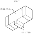
- the protrusion 511 of the support block 510 may have various shapes. That is, as shown in FIG. 6 , the protrusion 511 in the shape of straight lines orthogonal to each other may be formed, or as shown in FIG. 7 , the protrusion 511 in the shape of one straight line may be formed.
- the shape of the protrusion 511 is not limited thereto, and more various shapes of the protrusions 511 may be provided.
- the plurality of support blocks 510 are coupled to at least a portion of the plurality of receiving grooves 310 to form a flow path 600. And, referring to FIG. 3 , the cooling pipe 400 is inserted into the flow path 600.
- the flow path 600 may be variably provided according to the number and position of the plurality of support blocks 510a, 510b coupled to the plurality of receiving grooves 310, so that the shape of the flow path 600 may be changed with respect to the cooling pipe 400 having various shapes.
- the cooling pipe 400 having a shape as shown in FIG. 3 may be supported by the plurality of support blocks 510, or the cooling pipe 400 having a deformed shape as shown in FIG. 5 may also be supported by the plurality of support blocks 510 whose arrangement is changed.
- the support structure 500 includes the plurality of support blocks 510 having various shapes, and the plurality of support blocks 510 are coupled to the plurality of receiving grooves 310 to form the flow path 600 into which the cooling pipe 400 may be inserted.
- the plurality of support blocks 510 may support the cooling pipe 400 having various shapes even if the shape of the cooling pipe 400 inserted into the flow path 600 is changed.
- the electrical member 700 is coupled to various portions of the case 200.
- the electrical member 700 may be coupled to the outer side of the case 200.
- the electrical member 700 may be coupled to the inside of the case 200.
- the electrical member 700 may be configured to include an electrical case 710 and an electrical cover 720.
- Various electrical equipment 730 are accommodated in the electrical case 710, thereby protecting the electrical equipment 730 from external impact.
- the electrical cover 720 is coupled to the electrical case 710.
- cooling pipe 400 in the first embodiment has various shapes according to the various arrangement of the plurality of battery cells 100, so may the cooling pipe 740 in the second embodiment have various shapes according to the arrangement of the electrical equipment 730 provided in the electrical member 700.
- the support structure 750 supports the cooling pipe 740 and is variably provided to correspond to the shape of the cooling pipe 740.
- the support structure 750 in the second embodiment is basically common to the support structure 500 in the first embodiment in configuration.
- a vehicle (not shown) may include the above-described battery module 10 or the battery pack (not shown), and the battery pack (not shown) may include the battery module 10.
- the battery module 10 according to an embodiment of the present disclosure may be applied to the vehicle (not shown), for example, a predetermined vehicle (not shown) configured to use electricity, such as an electric vehicle or a hybrid vehicle.
- the present disclosure relates to a battery module, and a battery pack and a vehicle including the same, and in particular, may be used in industries related to secondary batteries.
Landscapes
- Engineering & Computer Science (AREA)
- Chemical Kinetics & Catalysis (AREA)
- General Chemical & Material Sciences (AREA)
- Electrochemistry (AREA)
- Chemical & Material Sciences (AREA)
- Manufacturing & Machinery (AREA)
- Aviation & Aerospace Engineering (AREA)
- Microelectronics & Electronic Packaging (AREA)
- Physics & Mathematics (AREA)
- Thermal Sciences (AREA)
- Life Sciences & Earth Sciences (AREA)
- Sustainable Development (AREA)
- Sustainable Energy (AREA)
- Power Engineering (AREA)
- Transportation (AREA)
- Mechanical Engineering (AREA)
- Secondary Cells (AREA)
- Battery Mounting, Suspending (AREA)
Abstract
Description
- The present application claims priority to
Korean Patent Application No. 10-2021-0080409 filed on June 21, 2021 - The present disclosure relates to a battery module, and a battery pack and a vehicle including the same, and more specifically, to a battery module provided with a variable support structure of a cooling pipe, and a battery pack and a vehicle including the same.
- As technology development and demand for mobile devices increase, the demand for secondary batteries as an energy source is rapidly increasing. In the related art, nickel cadmium batteries or hydrogen ion batteries have been used as secondary batteries, but recently, lithium secondary batteries in which they have almost no memory effect compared to nickel-based secondary batteries, resulting in free charge/discharge, very low self-discharge rate, and high energy density, have been widely used.
- Such a lithium secondary battery mainly uses a lithium-based oxide and a carbon material as a positive electrode active material and a negative electrode active material, respectively. The lithium secondary battery includes an electrode assembly in which a positive electrode plate and a negative electrode plate coated with the positive electrode active material and the negative electrode active material, respectively are disposed with a separator interposed therebetween, and a casing, that is, a battery case, for sealing and accommodating the electrode assembly along with an electrolyte.
- The lithium secondary battery includes a positive electrode, a negative electrode, a separator interposed therebetween, and an electrolyte, and is classified into a lithium-ion battery (LIB), a polymer lithium-ion battery (PLIB), and the like depending on which positive electrode and negative electrode active materials to be used. In general, the electrodes of these lithium secondary batteries may be formed by coating a positive electrode or negative electrode active material on a current collector such as an aluminum or copper sheet, mesh, film, foil, or the like, followed by drying. Also, various types of secondary batteries include a case capable of protecting battery cells, a battery module in which a plurality of battery cells are stacked to be inserted into the case, and a battery pack including a plurality of battery modules.
- Meanwhile, a cooling pipe through which water or air moves to cool the battery cells may be installed in the battery module.
- Here, the battery cells may be stacked or accommodated in the case in various ways. Since there is a difference in a portion where heat is generated according to a stacking method or an accommodating method of the battery cells, the shape of the cooling pipe is also changed.
- In the related art, when the shape of the cooling pipe is changed due to the change in arrangement of the battery cells, a structure supporting the cooling pipe should be individually provided for each shape of the cooling pipe according to the arrangement of the battery cells, thereby causing a problem of cost increase.
- In addition, electrical equipment related to electricity may be provided in the battery module. Although heat is generated in the electrical equipment, a cooling device is not provided or cooling is performed simply using a cooling fan in the past, thereby causing a problem that cooling efficiency is low.
- The present disclosure is designed to solve the problems of the related art, and therefore the present disclosure is directed to providing a battery module having a variable support structure to support the cooling pipe even if the shape of the cooling pipe is changed, and a battery pack and a vehicle including the same.
- In one aspect of the present disclosure, there is provided a battery module including a plurality of battery cells; a case configured to accommodate the plurality of battery cells; a cover coupled to the case; a cooling pipe disposed between the case and the cover to cool the plurality of battery cells; and a support structure that supports the cooling pipe and is variably provided to correspond to the shape of the cooling pipe.
- In addition, a plurality of receiving grooves are formed in the cover, and the support structure may include a plurality of support blocks in which protrusions are formed to be respectively coupled to the plurality of receiving grooves.
- Also, the plurality of receiving grooves may be arranged in a predetermined shape, the plurality of support blocks may be coupled to at least a portion of the plurality of receiving grooves to form a flow path, and the cooling pipe may be inserted into the flow path.
- In addition, the plurality of support blocks may be provided to be in contact with the cooling pipe to support the cooling pipe, when the cooling pipe is inserted into the flow path.
- Also, the flow path may be variably provided according to the number and position of the plurality of support blocks coupled to the plurality of receiving grooves.
- Meanwhile, in another aspect of the present disclosure, there is provided a battery module including a plurality of battery cells; a case configured to accommodate the plurality of battery cells; an electrical member coupled to the case; a cooling pipe disposed in the electrical member to cool the electrical member; and a support structure that supports the cooling pipe and is variably provided to correspond to the shape of the cooling pipe.
- In addition, the electrical member may include an electrical case to accommodate electrical equipment; and an electrical cover coupled to the electrical case, and the cooling pipe may be disposed between the electrical case and the electrical cover to cool the electrical equipment.
- Also, a plurality of receiving grooves are formed in the electrical cover, and the support structure may include a plurality of support blocks in which protrusions are formed to be respectively coupled to the plurality of receiving grooves.
- In addition, the plurality of receiving grooves may be arranged in a predetermined shape, the plurality of support blocks may be coupled to at least a portion of the plurality of receiving grooves to form a flow path, and the cooling pipe may be inserted into the flow path.
- Also, the plurality of support blocks may be provided to be in contact with the cooling pipe to support the cooling pipe, when the cooling pipe is inserted into the flow path.
- In addition, the flow path may be variably provided according to the number and position of the plurality of support blocks coupled to the plurality of receiving grooves.
- Meanwhile, in another aspect of the present disclosure, there is provided a battery pack including the battery module. And, there is also provided a vehicle including the battery module.
- According to embodiments of the present disclosure, the support structure is variably provided to support the cooling pipe even if the shape of the cooling pipe is changed, which enables to support the cooling pipe of various shapes, thereby reducing the cost.
-
-
FIG. 1 is an overall perspective view of a battery module according to the first embodiment of the present disclosure. -
FIG. 2 is an exploded perspective view ofFIG. 1 . -
FIG. 3 is a view illustrating a state in which a cooling pipe is disposed on a cover and supported by support blocks in the battery module according to the first embodiment of the present disclosure. -
FIG. 4 is a view in which the cooling pipe inFIG. 3 is removed. -
FIG. 5 is a view illustrating a cooling pipe having a different shape compared toFIG. 3 is disposed on the cover. -
FIGS. 6 and7 are perspective views of support blocks having various shapes in the battery module according to the first embodiment of the present disclosure. -
FIG. 8 is an exploded perspective view of an electrical member provided in the battery module according to the second embodiment of the present disclosure. - Hereinafter, preferred embodiments of the present disclosure will be described in detail with reference to the accompanying drawings. It should be understood that the terms used in the specification and the appended claims should not be construed as limited to general and dictionary meanings, but interpreted based on the meanings and concepts corresponding to technical aspects of the present disclosure on the basis of the principle that the inventor is allowed to define terms appropriately for the best explanation. Therefore, the description proposed herein is just a preferable example for the purpose of illustrations only, not intended to limit the scope of the disclosure, so it should be understood that other equivalents and modifications could be made thereto without departing from the scope of the disclosure.
- In the drawings, the size of each component or a specific portion constituting the component is exaggerated, omitted, or schematically illustrated for convenience and clarity of description. Therefore, the size of each component does not fully reflect the actual size. When it is determined that a detailed description of a related known function or configuration may unnecessarily obscure the gist of the present disclosure, such description will be omitted.
- As used herein, the term 'coupled' or 'connected' refers to not only a case in which one member and another member are directly coupled or directly connected, but also a case in which one member is indirectly coupled or indirectly connected to another member through a joint member.
-
FIG. 1 is an overall perspective view of a battery module according to the first embodiment of the present disclosure, andFIG. 2 is an exploded perspective view ofFIG. 1 .FIG. 3 is a view illustrating a state in which a cooling pipe is disposed on a cover and supported by support blocks in the battery module according to the first embodiment of the present disclosure, andFIG. 4 is a view in which the cooling pipe inFIG. 3 is removed.FIG. 5 is a view illustrating a cooling pipe having a different shape compared toFIG. 3 is disposed on the cover, andFIGS. 6 and7 are perspective views of support blocks having various shapes in the battery module according to the first embodiment of the present disclosure. - Referring to the drawings, the
battery module 10 according to the first embodiment of the present disclosure includesbattery cells 100, acase 200, acover 300, acooling pipe 400, and asupport structure 500. - Referring to
FIGS. 1 and2 , the plurality ofbattery cells 100 are accommodated in thecase 200 and protected. Here, thebattery cell 100 may vary. For example, thebattery cell 100 may be provided as a pouch-type battery cell 100, or may be provided as acylindrical battery cell 100. - The
battery cell 100 includes an electrode lead, wherein the electrode lead provided in thebattery cell 100 is a kind of terminal connected to an external device, and may be made of a conductive material. - The electrode lead may include a positive electrode lead and a negative electrode lead. The positive electrode lead and the negative electrode lead may be disposed in opposite directions with respect to the longitudinal direction of the
battery cell 100, or the positive electrode lead and the negative electrode lead may be disposed in the same direction with respect to the longitudinal direction of thebattery cell 100. - The positive electrode lead and the negative electrode lead may be made of various materials. For example, the positive electrode lead may be made of an aluminum material, and the negative electrode lead may be made of a copper material.
- The electrode lead may be electrically coupled to a bus bar. The
battery cell 100 may have a structure in which a plurality of unit cells arranged in the order of positive electrode plate-separator-negative electrode plate or a plurality of bi-cells arranged in the order of positive electrode plate-separator-negative electrode plate-separator-positive electrode plate-separator-negative electrode plate are stacked according to the battery capacity. - The plurality of
battery cells 100 may be variously accommodated in thecase 200. For example, the plurality ofbattery cells 100 may be stacked on each other to be accommodated in the form of a stack of thebattery cell 100. Here, thebattery cell 100 may have various structures, and the plurality ofbattery cells 100 may be stacked in various ways. - The stack of the
battery cell 100 may include a plurality of cartridges (not shown) accommodating eachbattery cell 100. Each cartridge (not shown) may be manufactured by injection molding of plastic, and the plurality of cartridges (not shown) in which an accommodating portion capable of accommodating thebattery cell 100 is formed may be stacked. - A connector element or a terminal element may be provided in a cartridge assembly in which the plurality of cartridges (not shown) are stacked. The connector element may include, for example, various types of electrical connection parts or connection members to be connected to a battery management system (BMS, not shown) capable of providing data on the voltage or temperature of the
battery cell 100. - Also, the terminal element, as a main terminal connected to the
battery cell 100, includes a positive electrode terminal and a negative electrode terminal. - Referring to
FIGS. 1 and2 , thecase 200 accommodates the plurality ofbattery cells 100, for example, the stack of thebattery cell 100 or the cartridge assembly in which the stack of thebattery cell 100 is accommodated. - The
case 200 may be provided in various ways, and for example, as shown inFIG. 2 , may be configured to include anupper case 210 and alower case 220. However, this is only one embodiment, and thecase 200 may be provided in more various ways. - Here, the
case 200 may be provided to surround the stack of thebattery cell 100 by thebattery cells 100 or the cartridge assembly in which the stack of thebattery cell 100 is accommodated. That is, thecase 200 surrounds theentire battery cells 100, thereby protecting thebattery cells 100 from external vibration or impact. - The
case 200 may be formed in a shape corresponding to the shape of thebattery cells 100, for example, the stack of thebattery cell 100 or the cartridge assembly. For example, when the stack of thebattery cell 100 or the cartridge assembly is provided in a hexahedral shape, thecase 200 may also be provided in a hexahedral shape to correspond to it. - The
cover 300 is coupled to thecase 200. Referring toFIGS. 1 and2 , thecover 300 may be coupled to a lower side of thecase 200. However, the coupling portion of thecover 300 may vary. - A plurality of receiving
grooves 310 to which a plurality of support blocks 510 are coupled are formed in thecover 300. A detailed description of the plurality of receivinggrooves 310 will be given later. - The
cooling pipe 400 is disposed between thecase 200 and thecover 300 to cool the plurality ofbattery cells 100. Thecooling pipe 400 is a flow path through which water or air moves, and may have various shapes depending on the arrangement of the plurality ofbattery cells 100. - The
support structure 500 supports thecooling pipe 400. In addition, thesupport structure 500 is variably provided to correspond to various shapes of thecooling pipe 400. That is, when the heating portion changes according to the stacking method or arrangement of the plurality ofbattery cells 100, the shape of thecooling pipe 400 also changes accordingly. In addition, thesupport structure 500 is also changed to support thecooling pipe 400 having a changed shape. - That is, since the
battery module 10 according to the first embodiment of the present disclosure may support thecooling pipe 400 having various shapes through thevariable support structure 500, it is easy to manufacture and has an effect of cost reduction. - Referring to
FIGS. 2 and3 , thesupport structure 500 includes a plurality of support blocks 510 in which protrusions 511 (refer toFIGS. 6 and7 ) are formed to be respectively coupled to the plurality of receivinggrooves 310. - The support block 510 may have various shapes. For example, as shown in
FIGS. 3 and6 , thesupport block 510a may be formed in a rectangular shape and disposed in the inner center of thecover 300 and in the vicinity of the center. Here, a round may be formed at a corner of thesupport block 510a. - Also, for example, referring to
FIGS. 3 and7 , thesupport block 510b may be provided to have a smaller size than thesupport block 510a and disposed on the edge of thecover 300. - However, the size and shape of the support block 510 are not limited to
FIGS. 6 and7 , and may be more diverse. - The plurality of receiving
grooves 310 are formed in thecover 300. Here, there may be various ways in which the plurality of receivinggrooves 310 are formed in thecover 300. For example, thecover 300 may be provided so that the receivinggroove 310 is formed in an intaglio shape. - Alternatively, as shown in
FIG. 3 , a plurality of embossedprotrusions 320 may be formed on thecover 300, and the receivinggrooves 310 may be formed between the plurality ofprotrusions 320. - In addition, the plurality of receiving
grooves 310 may be arranged in a predetermined shape. For example, as shown inFIG. 3 , the plurality of receivinggrooves 310 may be arranged such that horizontal grooves and vertical grooves having the same spacing are orthogonal to each other. However, the arrangement of the plurality of receivinggrooves 310 is not limited thereto. - Also, protrusions 511 may be formed in the plurality of support blocks 510 as shown in
FIGS. 6 and7 , and the protrusions 511 may be provided to be respectively coupled to the plurality of receivinggrooves 310. That is, a protrusion 511 having a shape corresponding to the shape of the receivinggroove 310 is formed in each of the support blocks 510, and the protrusion 511 of the support block 510 is inserted into the receivinggroove 310. - Referring to
FIGS. 6 and7 , the protrusion 511 of the support block 510 may have various shapes. That is, as shown inFIG. 6 , the protrusion 511 in the shape of straight lines orthogonal to each other may be formed, or as shown inFIG. 7 , the protrusion 511 in the shape of one straight line may be formed. - However, the shape of the protrusion 511 is not limited thereto, and more various shapes of the protrusions 511 may be provided.
- Referring to
FIG. 4 , the plurality of support blocks 510 are coupled to at least a portion of the plurality of receivinggrooves 310 to form aflow path 600. And, referring toFIG. 3 , thecooling pipe 400 is inserted into theflow path 600. - Here, when the
cooling pipe 400 is inserted into theflow path 600, the plurality of support blocks 510 come into contact with thecooling pipe 400 to support thecooling pipe 400. - That is, the
flow path 600 may be variably provided according to the number and position of the plurality ofsupport blocks grooves 310, so that the shape of theflow path 600 may be changed with respect to thecooling pipe 400 having various shapes. - Also, the
cooling pipe 400 may be inserted into theflow path 600 to be supported by the plurality of support blocks 510. - For example, the
cooling pipe 400 having a shape as shown inFIG. 3 may be supported by the plurality of support blocks 510, or thecooling pipe 400 having a deformed shape as shown inFIG. 5 may also be supported by the plurality of support blocks 510 whose arrangement is changed. - Hereinafter, the operation and effect of the
battery module 10 according to the first embodiment of the present disclosure will be described with reference to the drawings. - The plurality of
battery cells 100 included in thebattery module 10 of the present disclosure may be disposed in thecase 200 in various ways. In this case, the heating portion may be changed, and the shape of thecooling pipe 400 for cooling the heating portion should also be changed according to the change of the heating portion. - In addition, as shown in
FIGS. 3 and5 , when the shape of thecooling pipe 400 is changed, thesupport structure 500 for supporting thecooling pipe 400 should also be changed. In the case of thebattery module 10 according to the first embodiment of the present disclosure, thesupport structure 500 is variably provided. - The
support structure 500 includes the plurality of support blocks 510 having various shapes, and the plurality of support blocks 510 are coupled to the plurality of receivinggrooves 310 to form theflow path 600 into which thecooling pipe 400 may be inserted. - Here, since the
flow path 600 may have various shapes according to the number and position of the plurality of support blocks 510, the plurality of support blocks 510 may support thecooling pipe 400 having various shapes even if the shape of thecooling pipe 400 inserted into theflow path 600 is changed. -
FIG. 8 is an exploded perspective view of an electrical member provided in the battery module according to the second embodiment of the present disclosure. - Hereinafter, the cooling of an
electrical member 700 provided in thebattery module 10 will be described, but a portion common to the cooling method of thebattery cell 100 in the first embodiment described above will be replaced with the above-mentioned description. - Referring to
FIG. 8 , theelectrical member 700 refers to a member provided withelectrical equipment 730 related to electricity, such as a relay and a bus bar, and heat is generated by electricity. Therefore, theelectrical member 700 also needs cooling. - The description of the plurality of
battery cells 100 and thecase 200 in which the plurality ofbattery cells 100 are accommodated will be replaced with the description of the above-mentioned first embodiment. However, the structure for cooling thebattery cells 100 in the second embodiment may be the same as in the first embodiment described above, or may be provided to cool thebattery cells 100 in a different manner. - The
electrical member 700 is coupled to various portions of thecase 200. For example, as shown inFIG. 1 , theelectrical member 700 may be coupled to the outer side of thecase 200. In addition, although not shown in the drawings, theelectrical member 700 may be coupled to the inside of thecase 200. - The
electrical member 700 may be configured to include anelectrical case 710 and anelectrical cover 720. Variouselectrical equipment 730 are accommodated in theelectrical case 710, thereby protecting theelectrical equipment 730 from external impact. And, theelectrical cover 720 is coupled to theelectrical case 710. - A plurality of receiving
grooves 721 to which a plurality of support blocks 751 are coupled are formed in theelectrical cover 720. A detailed description of the plurality of receivinggrooves 721 will be given later. - The
cooling pipe 740 is disposed in theelectrical member 700 to cool theelectrical member 700. For example, thecooling pipe 740 may be disposed between theelectrical case 710 and theelectrical cover 720 of theelectrical member 700 to cool theelectrical equipment 730 provided in theelectrical member 700. - The
cooling pipe 740 of the second embodiment is different from the first embodiment of cooling thebattery cell 100 in that theelectrical member 700 is cooled. - However, just as the
cooling pipe 400 in the first embodiment has various shapes according to the various arrangement of the plurality ofbattery cells 100, so may the coolingpipe 740 in the second embodiment have various shapes according to the arrangement of theelectrical equipment 730 provided in theelectrical member 700. - That is, in the first embodiment, the
cooling pipe 400 cools the plurality ofbattery cells 100, and in the second embodiment, thecooling pipe 740 cools theelectrical equipment 730 provided in theelectrical member 700. In this respect, there is a difference in the object of cooling, but other basic configurations are common. - The
support structure 750 supports thecooling pipe 740 and is variably provided to correspond to the shape of thecooling pipe 740. Thesupport structure 750 in the second embodiment is basically common to thesupport structure 500 in the first embodiment in configuration. - The
support structure 750 includes the plurality of support blocks 751 in which protrusions 755 (refer toFIGS. 6 and7 ) are formed to be respectively coupled to the plurality of receivinggrooves 721. Here, the detailed description of the plurality of receivinggrooves 721 and the plurality of support blocks 751, for example, thesupport block 751a and thesupport block 751b, and the protrusion 755 is common to that of thesupport block 510a and thesupport block 510b, and the protrusion 511 in the first embodiment, and thus, will be replaced with the description of the first embodiment. - That is, the plurality of support blocks 751 and the plurality of receiving
grooves 721 are coupled to form a flow path 760, and thecooling pipe 740 is inserted into the flow path 760. The plurality of support blocks 751 are in contact with thecooling pipe 740 to support thecooling pipe 740, and in this case, the configuration in which the flow path 760 is variably provided according to the number and position of the plurality of support blocks 751 is in common with the first embodiment. - Meanwhile, a battery pack (not shown) according to an embodiment of the present disclosure may include one or
more battery modules 10 according to an embodiment of the present disclosure as described above. Also, the battery pack (not shown) may further include a housing for accommodating thebattery module 10, various devices for controlling charge/discharge of thebattery module 10, such as a BMS, a current sensor, a fuse, and the like, in addition to thebattery module 10. - Meanwhile, a vehicle (not shown) according to an embodiment of the present disclosure may include the above-described
battery module 10 or the battery pack (not shown), and the battery pack (not shown) may include thebattery module 10. In addition, thebattery module 10 according to an embodiment of the present disclosure may be applied to the vehicle (not shown), for example, a predetermined vehicle (not shown) configured to use electricity, such as an electric vehicle or a hybrid vehicle. - The present disclosure has been described in detail. However, it should be understood that the detailed description and specific examples, while indicating preferred embodiments of the disclosure, are given by way of illustration only, since various changes and modifications within the scope of the disclosure will become apparent to those skilled in the art from this detailed description.
- The present disclosure relates to a battery module, and a battery pack and a vehicle including the same, and in particular, may be used in industries related to secondary batteries.
Claims (13)
- A battery module comprising:a plurality of battery cells;a case configured to accommodate the plurality of battery cells;a cover coupled to the case;a cooling pipe disposed between the case and the cover to cool the plurality of battery cells; anda support structure that supports the cooling pipe and is variably provided to correspond to the shape of the cooling pipe.
- The battery module according to claim 1,wherein a plurality of receiving grooves are formed in the cover, andthe support structure comprises a plurality of support blocks in which protrusions are formed to be respectively coupled to the plurality of receiving grooves.
- The battery module according to claim 2,wherein the plurality of receiving grooves are arranged in a predetermined shape,the plurality of support blocks are coupled to at least a portion of the plurality of receiving grooves to form a flow path, andthe cooling pipe is inserted into the flow path.
- The battery module according to claim 3,
wherein the plurality of support blocks are in contact with the cooling pipe to support the cooling pipe, when the cooling pipe is inserted into the flow path. - The battery module according to claim 4,
wherein the flow path is variably provided according to the number and position of the plurality of support blocks coupled to the plurality of receiving grooves. - A battery module comprising:a plurality of battery cells;a case configured to accommodate the plurality of battery cells;an electrical member coupled to the case;a cooling pipe disposed in the electrical member to cool the electrical member; anda support structure that supports the cooling pipe and is variably provided to correspond to the shape of the cooling pipe.
- The battery module according to claim 6,
wherein the electrical member comprises:an electrical case to accommodate electrical equipment; andan electrical cover coupled to the electrical case, andthe cooling pipe is disposed between the electrical case and the electrical cover to cool the electrical equipment. - The battery module according to claim 7,wherein a plurality of receiving grooves are formed in the electrical cover, andthe support structure comprises a plurality of support blocks in which protrusions are formed to be respectively coupled to the plurality of receiving grooves.
- The battery module according to claim 8,wherein the plurality of receiving grooves are arranged in a predetermined shape,the plurality of support blocks are coupled to at least a portion of the plurality of receiving grooves to form a flow path, andthe cooling pipe is inserted into the flow path.
- The battery module according to claim 9,
wherein the plurality of support blocks are in contact with the cooling pipe to support the cooling pipe, when the cooling pipe is inserted into the flow path. - The battery module according to claim 10,
wherein the flow path is variably provided according to the number and position of the plurality of support blocks coupled to the plurality of receiving grooves. - A battery pack comprising the battery module according to any one of claims 1 to 11.
- A vehicle comprising the battery module according to any one of claims 1 to 11.
Applications Claiming Priority (2)
| Application Number | Priority Date | Filing Date | Title |
|---|---|---|---|
| KR1020210080409A KR20220169832A (en) | 2021-06-21 | 2021-06-21 | Battery module and battery pack including the same and vehicle including the same |
| PCT/KR2022/000399 WO2022270705A1 (en) | 2021-06-21 | 2022-01-10 | Battery module, and battery pack and vehicle comprising same |
Publications (3)
| Publication Number | Publication Date |
|---|---|
| EP4258425A1 true EP4258425A1 (en) | 2023-10-11 |
| EP4258425A4 EP4258425A4 (en) | 2024-07-31 |
| EP4258425B1 EP4258425B1 (en) | 2025-10-15 |
Family
ID=84538445
Family Applications (1)
| Application Number | Title | Priority Date | Filing Date |
|---|---|---|---|
| EP22828558.1A Active EP4258425B1 (en) | 2021-06-21 | 2022-01-10 | Battery module, and battery pack and vehicle comprising same |
Country Status (6)
| Country | Link |
|---|---|
| EP (1) | EP4258425B1 (en) |
| JP (1) | JP7522320B2 (en) |
| KR (1) | KR20220169832A (en) |
| CN (1) | CN116569387A (en) |
| ES (1) | ES3053282T3 (en) |
| WO (1) | WO2022270705A1 (en) |
Family Cites Families (14)
| Publication number | Priority date | Publication date | Assignee | Title |
|---|---|---|---|---|
| KR101112442B1 (en) * | 2008-10-14 | 2012-02-20 | 주식회사 엘지화학 | Battery Module Assembly of Improved Cooling Efficiency |
| JP2011175743A (en) * | 2010-02-23 | 2011-09-08 | Sanyo Electric Co Ltd | Power source apparatus, and vehicle equipped with the same |
| US9196938B2 (en) * | 2010-07-06 | 2015-11-24 | Samsung Sdi Co., Ltd. | Battery module |
| US8507062B2 (en) * | 2010-08-27 | 2013-08-13 | International Business Machines Corporation | Flexible-to-rigid tubing |
| KR20130008142A (en) | 2011-07-12 | 2013-01-22 | 에스케이이노베이션 주식회사 | Secondary battery pack |
| JP5899132B2 (en) * | 2013-01-31 | 2016-04-06 | 日立オートモティブシステムズ株式会社 | Power storage module |
| US9901014B2 (en) * | 2016-04-15 | 2018-02-20 | Ford Global Technologies, Llc | Peristaltic pump for power electronics assembly |
| KR102391118B1 (en) * | 2017-06-07 | 2022-04-27 | 삼성에스디아이 주식회사 | Battery pack |
| KR102378425B1 (en) * | 2017-06-07 | 2022-03-24 | 삼성에스디아이 주식회사 | Battery pack |
| KR20190036379A (en) * | 2017-09-27 | 2019-04-04 | 엠에이치기술개발 주식회사 | Cooling plate |
| KR102301195B1 (en) * | 2017-12-01 | 2021-09-09 | 주식회사 엘지에너지솔루션 | Battery pack |
| KR102317274B1 (en) * | 2017-12-11 | 2021-10-22 | 주식회사 엘지에너지솔루션 | Battery module and battery pack including the same |
| CN110635193B (en) * | 2018-06-22 | 2024-02-27 | 陕西汽车集团股份有限公司 | Manufacturing method of liquid cooling plate structure with freely-built cooling flow channel |
| ES2968740T3 (en) | 2019-12-19 | 2024-05-13 | Wanhua Chemical Group Co Ltd | Procedure for the treatment of production wastewater from the preparation of propylene oxide by co-oxidation procedure |
-
2021
- 2021-06-21 KR KR1020210080409A patent/KR20220169832A/en active Pending
-
2022
- 2022-01-10 EP EP22828558.1A patent/EP4258425B1/en active Active
- 2022-01-10 CN CN202280007631.9A patent/CN116569387A/en active Pending
- 2022-01-10 ES ES22828558T patent/ES3053282T3/en active Active
- 2022-01-10 WO PCT/KR2022/000399 patent/WO2022270705A1/en not_active Ceased
- 2022-01-10 JP JP2023534036A patent/JP7522320B2/en active Active
Also Published As
| Publication number | Publication date |
|---|---|
| ES3053282T3 (en) | 2026-01-21 |
| EP4258425B1 (en) | 2025-10-15 |
| CN116569387A (en) | 2023-08-08 |
| US20230420770A1 (en) | 2023-12-28 |
| JP7522320B2 (en) | 2024-07-24 |
| EP4258425A4 (en) | 2024-07-31 |
| KR20220169832A (en) | 2022-12-28 |
| WO2022270705A1 (en) | 2022-12-29 |
| JP2023553003A (en) | 2023-12-20 |
Similar Documents
| Publication | Publication Date | Title |
|---|---|---|
| US11121395B2 (en) | Battery module with movable end plate responsive to cell swelling and battery pack including same | |
| KR102301195B1 (en) | Battery pack | |
| EP4184667B1 (en) | Battery module, and battery pack and vehicle comprising same | |
| US20250079548A1 (en) | Battery Module, and Battery Pack and Vehicle Comprising Same | |
| EP4138190A1 (en) | Battery module, and battery pack and automobile including same | |
| EP4386958B1 (en) | Battery module, and battery pack and vehicle including the same | |
| CN216958271U (en) | Battery module, battery pack including same and vehicle | |
| EP4379909A1 (en) | Battery module, and battery pack and vehicle comprising same | |
| US12021212B2 (en) | Battery module, and battery pack and vehicle comprising same | |
| EP3514004B1 (en) | Battery module and battery pack including same | |
| KR20220047057A (en) | Battery module and battery pack including the same and vehicle including the same | |
| EP4258425B1 (en) | Battery module, and battery pack and vehicle comprising same | |
| US12633593B2 (en) | Battery module, and battery pack and vehicle including the same | |
| KR20220100424A (en) | Battery module and battery pack including the same and vehicle including the same | |
| EP4336639B1 (en) | Battery module and battery pack and vehicle comprising same | |
| EP4075573A1 (en) | Battery module, and battery pack and vehicle comprising same |
Legal Events
| Date | Code | Title | Description |
|---|---|---|---|
| STAA | Information on the status of an ep patent application or granted ep patent |
Free format text: STATUS: THE INTERNATIONAL PUBLICATION HAS BEEN MADE |
|
| PUAI | Public reference made under article 153(3) epc to a published international application that has entered the european phase |
Free format text: ORIGINAL CODE: 0009012 |
|
| STAA | Information on the status of an ep patent application or granted ep patent |
Free format text: STATUS: REQUEST FOR EXAMINATION WAS MADE |
|
| 17P | Request for examination filed |
Effective date: 20230706 |
|
| AK | Designated contracting states |
Kind code of ref document: A1 Designated state(s): AL AT BE BG CH CY CZ DE DK EE ES FI FR GB GR HR HU IE IS IT LI LT LU LV MC MK MT NL NO PL PT RO RS SE SI SK SM TR |
|
| REG | Reference to a national code |
Ref country code: DE Ref legal event code: R079 Free format text: PREVIOUS MAIN CLASS: H01M0010655600 Ipc: H01M0010625000 Ref document number: 602022023211 Country of ref document: DE |
|
| A4 | Supplementary search report drawn up and despatched |
Effective date: 20240701 |
|
| RIC1 | Information provided on ipc code assigned before grant |
Ipc: H01M 10/647 20140101ALN20240625BHEP Ipc: H01M 10/613 20140101ALN20240625BHEP Ipc: H01M 10/6568 20140101ALI20240625BHEP Ipc: H01M 10/617 20140101ALI20240625BHEP Ipc: H01M 10/42 20060101ALI20240625BHEP Ipc: H01M 10/667 20140101ALI20240625BHEP Ipc: H01M 10/6556 20140101ALI20240625BHEP Ipc: H01M 10/625 20140101AFI20240625BHEP |
|
| DAV | Request for validation of the european patent (deleted) | ||
| DAX | Request for extension of the european patent (deleted) | ||
| GRAP | Despatch of communication of intention to grant a patent |
Free format text: ORIGINAL CODE: EPIDOSNIGR1 |
|
| STAA | Information on the status of an ep patent application or granted ep patent |
Free format text: STATUS: GRANT OF PATENT IS INTENDED |
|
| RIC1 | Information provided on ipc code assigned before grant |
Ipc: H01M 10/625 20140101AFI20250626BHEP Ipc: H01M 10/6556 20140101ALI20250626BHEP Ipc: H01M 10/667 20140101ALI20250626BHEP Ipc: H01M 10/42 20060101ALI20250626BHEP Ipc: H01M 10/617 20140101ALI20250626BHEP Ipc: H01M 10/6568 20140101ALI20250626BHEP Ipc: H01M 10/643 20140101ALI20250626BHEP Ipc: H01M 10/6557 20140101ALI20250626BHEP Ipc: H01M 10/6567 20140101ALI20250626BHEP Ipc: H01M 50/211 20210101ALI20250626BHEP Ipc: H01M 50/20 20210101ALI20250626BHEP Ipc: H01M 50/271 20210101ALI20250626BHEP Ipc: H01M 50/209 20210101ALI20250626BHEP Ipc: H01M 50/249 20210101ALI20250626BHEP Ipc: H01M 10/613 20140101ALN20250626BHEP Ipc: H01M 10/647 20140101ALN20250626BHEP |
|
| INTG | Intention to grant announced |
Effective date: 20250704 |
|
| GRAS | Grant fee paid |
Free format text: ORIGINAL CODE: EPIDOSNIGR3 |
|
| GRAA | (expected) grant |
Free format text: ORIGINAL CODE: 0009210 |
|
| STAA | Information on the status of an ep patent application or granted ep patent |
Free format text: STATUS: THE PATENT HAS BEEN GRANTED |
|
| P01 | Opt-out of the competence of the unified patent court (upc) registered |
Free format text: CASE NUMBER: UPC_APP_4901_4258425/2025 Effective date: 20250827 |
|
| AK | Designated contracting states |
Kind code of ref document: B1 Designated state(s): AL AT BE BG CH CY CZ DE DK EE ES FI FR GB GR HR HU IE IS IT LI LT LU LV MC MK MT NL NO PL PT RO RS SE SI SK SM TR |
|
| REG | Reference to a national code |
Ref country code: GB Ref legal event code: FG4D Ref country code: CH Ref legal event code: F10 Free format text: ST27 STATUS EVENT CODE: U-0-0-F10-F00 (AS PROVIDED BY THE NATIONAL OFFICE) Effective date: 20251015 |
|
| REG | Reference to a national code |
Ref country code: DE Ref legal event code: R096 Ref document number: 602022023211 Country of ref document: DE |
|
| REG | Reference to a national code |
Ref country code: IE Ref legal event code: FG4D |
|
| PGFP | Annual fee paid to national office [announced via postgrant information from national office to epo] |
Ref country code: GB Payment date: 20251222 Year of fee payment: 5 |
|
| PGFP | Annual fee paid to national office [announced via postgrant information from national office to epo] |
Ref country code: FR Payment date: 20251223 Year of fee payment: 5 |
|
| PGFP | Annual fee paid to national office [announced via postgrant information from national office to epo] |
Ref country code: BE Payment date: 20251229 Year of fee payment: 5 |
|
| REG | Reference to a national code |
Ref country code: ES Ref legal event code: FG2A Ref document number: 3053282 Country of ref document: ES Kind code of ref document: T3 Effective date: 20260121 |
|
| REG | Reference to a national code |
Ref country code: NL Ref legal event code: MP Effective date: 20251015 |
|
| PGFP | Annual fee paid to national office [announced via postgrant information from national office to epo] |
Ref country code: HU Payment date: 20260129 Year of fee payment: 5 |
|
| REG | Reference to a national code |
Ref country code: AT Ref legal event code: MK05 Ref document number: 1847846 Country of ref document: AT Kind code of ref document: T Effective date: 20251015 |
|
| PG25 | Lapsed in a contracting state [announced via postgrant information from national office to epo] |
Ref country code: NL Free format text: LAPSE BECAUSE OF FAILURE TO SUBMIT A TRANSLATION OF THE DESCRIPTION OR TO PAY THE FEE WITHIN THE PRESCRIBED TIME-LIMIT Effective date: 20251015 |
|
| PGFP | Annual fee paid to national office [announced via postgrant information from national office to epo] |
Ref country code: ES Payment date: 20260213 Year of fee payment: 5 |
|
| REG | Reference to a national code |
Ref country code: LT Ref legal event code: MG9D |
|
| PG25 | Lapsed in a contracting state [announced via postgrant information from national office to epo] |
Ref country code: NO Free format text: LAPSE BECAUSE OF FAILURE TO SUBMIT A TRANSLATION OF THE DESCRIPTION OR TO PAY THE FEE WITHIN THE PRESCRIBED TIME-LIMIT Effective date: 20260115 |
|
| PGFP | Annual fee paid to national office [announced via postgrant information from national office to epo] |
Ref country code: DE Payment date: 20251222 Year of fee payment: 5 |
|
| PG25 | Lapsed in a contracting state [announced via postgrant information from national office to epo] |
Ref country code: HR Free format text: LAPSE BECAUSE OF FAILURE TO SUBMIT A TRANSLATION OF THE DESCRIPTION OR TO PAY THE FEE WITHIN THE PRESCRIBED TIME-LIMIT Effective date: 20251015 Ref country code: FI Free format text: LAPSE BECAUSE OF FAILURE TO SUBMIT A TRANSLATION OF THE DESCRIPTION OR TO PAY THE FEE WITHIN THE PRESCRIBED TIME-LIMIT Effective date: 20251015 Ref country code: AT Free format text: LAPSE BECAUSE OF FAILURE TO SUBMIT A TRANSLATION OF THE DESCRIPTION OR TO PAY THE FEE WITHIN THE PRESCRIBED TIME-LIMIT Effective date: 20251015 |
|
| PG25 | Lapsed in a contracting state [announced via postgrant information from national office to epo] |
Ref country code: RS Free format text: LAPSE BECAUSE OF FAILURE TO SUBMIT A TRANSLATION OF THE DESCRIPTION OR TO PAY THE FEE WITHIN THE PRESCRIBED TIME-LIMIT Effective date: 20260115 |
|
| PG25 | Lapsed in a contracting state [announced via postgrant information from national office to epo] |
Ref country code: IS Free format text: LAPSE BECAUSE OF FAILURE TO SUBMIT A TRANSLATION OF THE DESCRIPTION OR TO PAY THE FEE WITHIN THE PRESCRIBED TIME-LIMIT Effective date: 20260215 |
|
| PG25 | Lapsed in a contracting state [announced via postgrant information from national office to epo] |
Ref country code: PT Free format text: LAPSE BECAUSE OF FAILURE TO SUBMIT A TRANSLATION OF THE DESCRIPTION OR TO PAY THE FEE WITHIN THE PRESCRIBED TIME-LIMIT Effective date: 20260216 |
|
| PG25 | Lapsed in a contracting state [announced via postgrant information from national office to epo] |
Ref country code: PL Free format text: LAPSE BECAUSE OF FAILURE TO SUBMIT A TRANSLATION OF THE DESCRIPTION OR TO PAY THE FEE WITHIN THE PRESCRIBED TIME-LIMIT Effective date: 20251015 |
|
| PG25 | Lapsed in a contracting state [announced via postgrant information from national office to epo] |
Ref country code: LV Free format text: LAPSE BECAUSE OF FAILURE TO SUBMIT A TRANSLATION OF THE DESCRIPTION OR TO PAY THE FEE WITHIN THE PRESCRIBED TIME-LIMIT Effective date: 20251015 |
|
| PG25 | Lapsed in a contracting state [announced via postgrant information from national office to epo] |
Ref country code: BG Free format text: LAPSE BECAUSE OF FAILURE TO SUBMIT A TRANSLATION OF THE DESCRIPTION OR TO PAY THE FEE WITHIN THE PRESCRIBED TIME-LIMIT Effective date: 20251015 |