EP4258401A1 - Secondary battery activating apparatus and secondary battery manufacturing method using same - Google Patents
Secondary battery activating apparatus and secondary battery manufacturing method using same Download PDFInfo
- Publication number
- EP4258401A1 EP4258401A1 EP22899005.7A EP22899005A EP4258401A1 EP 4258401 A1 EP4258401 A1 EP 4258401A1 EP 22899005 A EP22899005 A EP 22899005A EP 4258401 A1 EP4258401 A1 EP 4258401A1
- Authority
- EP
- European Patent Office
- Prior art keywords
- secondary battery
- pressing
- activation device
- elastic
- size
- Prior art date
- Legal status (The legal status is an assumption and is not a legal conclusion. Google has not performed a legal analysis and makes no representation as to the accuracy of the status listed.)
- Pending
Links
Images


Classifications
-
- H—ELECTRICITY
- H01—ELECTRIC ELEMENTS
- H01M—PROCESSES OR MEANS, e.g. BATTERIES, FOR THE DIRECT CONVERSION OF CHEMICAL ENERGY INTO ELECTRICAL ENERGY
- H01M10/00—Secondary cells; Manufacture thereof
- H01M10/04—Construction or manufacture in general
-
- H—ELECTRICITY
- H01—ELECTRIC ELEMENTS
- H01M—PROCESSES OR MEANS, e.g. BATTERIES, FOR THE DIRECT CONVERSION OF CHEMICAL ENERGY INTO ELECTRICAL ENERGY
- H01M10/00—Secondary cells; Manufacture thereof
- H01M10/04—Construction or manufacture in general
- H01M10/0404—Machines for assembling batteries
-
- H—ELECTRICITY
- H01—ELECTRIC ELEMENTS
- H01M—PROCESSES OR MEANS, e.g. BATTERIES, FOR THE DIRECT CONVERSION OF CHEMICAL ENERGY INTO ELECTRICAL ENERGY
- H01M10/00—Secondary cells; Manufacture thereof
- H01M10/04—Construction or manufacture in general
- H01M10/0481—Compression means other than compression means for stacks of electrodes and separators
-
- H—ELECTRICITY
- H01—ELECTRIC ELEMENTS
- H01M—PROCESSES OR MEANS, e.g. BATTERIES, FOR THE DIRECT CONVERSION OF CHEMICAL ENERGY INTO ELECTRICAL ENERGY
- H01M10/00—Secondary cells; Manufacture thereof
- H01M10/42—Methods or arrangements for servicing or maintenance of secondary cells or secondary half-cells
- H01M10/44—Methods for charging or discharging
- H01M10/446—Initial charging measures
-
- H—ELECTRICITY
- H01—ELECTRIC ELEMENTS
- H01M—PROCESSES OR MEANS, e.g. BATTERIES, FOR THE DIRECT CONVERSION OF CHEMICAL ENERGY INTO ELECTRICAL ENERGY
- H01M10/00—Secondary cells; Manufacture thereof
- H01M10/04—Construction or manufacture in general
- H01M10/049—Processes for forming or storing electrodes in the battery container
-
- H—ELECTRICITY
- H01—ELECTRIC ELEMENTS
- H01M—PROCESSES OR MEANS, e.g. BATTERIES, FOR THE DIRECT CONVERSION OF CHEMICAL ENERGY INTO ELECTRICAL ENERGY
- H01M10/00—Secondary cells; Manufacture thereof
- H01M10/05—Accumulators with non-aqueous electrolyte
- H01M10/058—Construction or manufacture
-
- Y—GENERAL TAGGING OF NEW TECHNOLOGICAL DEVELOPMENTS; GENERAL TAGGING OF CROSS-SECTIONAL TECHNOLOGIES SPANNING OVER SEVERAL SECTIONS OF THE IPC; TECHNICAL SUBJECTS COVERED BY FORMER USPC CROSS-REFERENCE ART COLLECTIONS [XRACs] AND DIGESTS
- Y02—TECHNOLOGIES OR APPLICATIONS FOR MITIGATION OR ADAPTATION AGAINST CLIMATE CHANGE
- Y02E—REDUCTION OF GREENHOUSE GAS [GHG] EMISSIONS, RELATED TO ENERGY GENERATION, TRANSMISSION OR DISTRIBUTION
- Y02E60/00—Enabling technologies; Technologies with a potential or indirect contribution to GHG emissions mitigation
- Y02E60/10—Energy storage using batteries
-
- Y—GENERAL TAGGING OF NEW TECHNOLOGICAL DEVELOPMENTS; GENERAL TAGGING OF CROSS-SECTIONAL TECHNOLOGIES SPANNING OVER SEVERAL SECTIONS OF THE IPC; TECHNICAL SUBJECTS COVERED BY FORMER USPC CROSS-REFERENCE ART COLLECTIONS [XRACs] AND DIGESTS
- Y02—TECHNOLOGIES OR APPLICATIONS FOR MITIGATION OR ADAPTATION AGAINST CLIMATE CHANGE
- Y02P—CLIMATE CHANGE MITIGATION TECHNOLOGIES IN THE PRODUCTION OR PROCESSING OF GOODS
- Y02P70/00—Climate change mitigation technologies in the production process for final industrial or consumer products
- Y02P70/50—Manufacturing or production processes characterised by the final manufactured product
Definitions
- the present invention relates to a secondary battery activation device capable of effectively removing gas generated inside a secondary battery cell during a secondary battery activation process and a secondary battery manufacturing method using the same.
- lithium secondary batteries such as lithium-ion batteries and lithium-ion polymer batteries, which have advantages such as high energy density, high discharge voltage, and output stability.
- secondary batteries are also classified according to the structure of the electrode assembly having a positive electrode/a separator/a negative electrode structure.
- a jelly-roll (wound type) type electrode assembly having a structure in which a long sheet-type positive electrodes and negative electrodes are wound with a separator interposed therebetween
- a stack-type (layered type) electrode assembly in which multiple positive electrodes and negative electrodes cut in units of a predetermined size are stacked in order with a separator interposed therebetween
- a stack-folding type electrode assembly having a structure of winding a bi-cell or a full cell in which positive electrodes and negative electrodes of a predetermined unit are layered with a separator interposed therebetween, etc.
- a pouch-type battery having a structure in which a stack-type or stack-folding type electrode assembly is embedded in a pouch-type battery case of an aluminum laminate sheet has attracted much attention due to low manufacturing cost, small weight, and easy shape variation, and its usage is also gradually increasing.
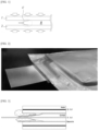
- FIG. 1 is a cross-sectional view schematically illustrating a secondary battery activation device according to the prior art
- FIG. 2 and FIG. 3 are images showing results obtained by performing a high-temperature pressurization activation process with a secondary battery activation device according to the prior art.
- the secondary battery activation device is composed of a plate-shaped upper pressing plate 1 and a lower pressing plate 2.
- a plate-shaped upper pressing plate 1 and lower pressing plate 2 press both sides of the secondary battery B at a high temperature while being heated with the secondary battery B interposed therebetween, so that the generated gas by charging is removed at the interface between the electrodes to activate the secondary battery B.
- the electrode constituting the secondary battery B when manufacturing the electrode constituting the secondary battery B, when the electrode material is coated in a slurry state, a slight flow phenomenon occurs until the end of the electrode is dried due to the fluidity of the slurry, and the thickness of the electrode becomes thin (a so-called sliding region of the electrode), thereby a difference in thickness occurs at the end of the electrode, resulting in an imbalance in the thickness of the secondary battery B (See C of FIG. 1 for reference).
- the present invention is directed to provide a secondary battery activation device in which gas generated during an activation process is not locally trapped in a cell by uniformly pressurizing the secondary battery cell during the secondary battery activation process, even if there is a part in the secondary battery cell that is locally thin, and a secondary battery manufacturing method using the same.
- the secondary battery activation device includes: an upper pressing unit including an upper pressing plate and multiple first elastic pressing members formed on the lower surface of the upper pressing plate; and a lower pressing unit including a lower pressing plate formed to face the upper pressing plate and multiple second elastic pressing members formed on the upper surface of the lower pressing plate.
- the first elastic pressing member includes an elastic member and a pressing block, an upper end of the elastic member is fixed to the lower surface of the upper pressing plate, and a lower end of the elastic member is fixed to the pressing block.
- the second elastic pressing member includes an elastic member and a pressing block, a lower end of the elastic member is fixed to the upper surface of the lower pressing plate, and an upper end of the elastic member is fixed to the pressing block.
- the elastic member may be a spring.
- the pressing block may have an elastic surface formed on a surface that presses a secondary battery.
- each of the pressing blocks constituting the first and the second elastic pressing members may be formed to have the same size in the entire pressing region for pressing the secondary battery.
- pressing blocks for pressing the first region in which the electrode thickness of the secondary battery is constant may be formed in a first size
- pressing blocks for pressing the second region in which the electrode thickness of the secondary battery becomes thin may be formed in a second size, which is smaller than the first size
- pressing blocks for pressing the second region may be formed to have a second size, which is smaller than the first size, and may be formed to become gradually smaller toward the end of the secondary battery.
- the pressing blocks may be formed in a stripe shape.
- the pressing blocks may be formed in a grid shape.
- a secondary battery manufacturing method is performed by using the above-described secondary battery activation device in the activation step of the secondary battery.
- the entire surface of the secondary battery cell is uniformly pressed, even if there is a part that is locally thin due to uneven thickness of the secondary battery cell, there is an effect of preventing gas generated inside the secondary battery cell from being trapped inside the electrode assembly during the secondary battery activation process.
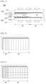
- FIG. 4 is a cross-sectional view schematically illustrating a secondary battery activation device according to the first embodiment of the present invention
- FIG. 5 is a diagram illustrating a pressing block formed in a stripe shape
- FIG. 6 is a diagram illustrating a pressing block formed in a grid shape.
- the secondary battery activation device 100 includes an upper pressing unit 110 and a lower pressing unit 120.
- the upper pressing unit 110 presses the upper surface of the secondary battery B at a high temperature
- the lower pressing unit 120 presses the lower surface of the secondary battery B at a high temperature.
- the upper pressing unit 110 includes an upper pressing plate 111 and multiple first elastic pressing members 112.
- the upper pressing plate 111 may be formed in a predetermined shape, for example, a rectangular plate shape, and multiple first elastic pressing members 112 may be formed on the lower surface of the upper pressing plate 111 at equal spacings.
- Each of the first elastic pressing members 112 includes an elastic member 112a and a pressing block 112b.
- the elastic member 112a may be a material capable of contracting/expanding by an external force, such as a spring or a synthetic rubber.
- the elastic member 112a is a spring.
- the upper end of the elastic member 112a is fixed to the lower surface of the upper pressing plate 111, and the lower end of the elastic member 112a is fixed to the pressing block 112b.
- the pressing block 112b may be formed in a stripe shape having a predetermined width and length.
- the pressing block 112b may be formed in a grid shape having a predetermined area.
- the pressing block 112b When the pressing block 112b is formed in a stripe shape as shown in FIG. 5 , there is an advantage in that manufacturing is relatively easy. Meanwhile, when the pressing block 112b is formed in a grid shape as shown in FIG. 6 , although manufacturing is relatively complicated, there is an advantage in that uniform pressurization is possible even with minute changes in the thickness of the secondary battery B.
- the pressing block 112b is formed of a solid material as a whole, but an elastic surface made of rubber or the like having a certain hardness may be formed on the surface on which the secondary battery B is pressed.
- the elastic surface prevents the surface of the secondary battery B from being damaged by the pressure of the pressing block 112b.
- the lower pressing unit 120 includes a lower pressing plate 121 facing the upper pressing plate 111 and multiple second elastic pressing members 122.
- the lower pressing plate 121 may be formed in a shape corresponding to the upper pressing plate 111, and multiple second elastic pressing members 122 may be formed at equal spacings on the upper surface of the lower pressing plate 121.
- Each of the second elastic pressing members 122 includes an elastic member 122a and a pressing block 122b.
- the secondary battery in the activation process of a pouch-type battery or a prismatic battery, the secondary battery can be uniformly pressed as a whole regardless of the flatness of the secondary battery.
- the activation process performed with uniform pressure allows the generated activated gas to be removed without local trapping, and thus a secondary battery in a uniformly charged state can be manufactured.
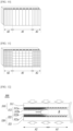
- FIG. 7 is a cross-sectional view schematically illustrating a secondary battery activation device according to the second embodiment of the present invention
- FIG. 8 to FIG. 11 are diagrams illustrating pressing blocks formed in various shapes.
- the secondary battery activation device 200 includes an upper pressing unit 210 and a lower pressing unit 220.
- the pressing blocks 212b, 222b since the rest of the components are substantially the same as the first embodiment described above, a repeated description will be omitted.
- the pressing blocks 212b, 222b are formed to have different sizes depending on the region where the secondary battery B is pressed. Specifically, the pressing blocks 212b, 222b for pressing the first region A1 in which the thickness of the electrode in the secondary battery B is constant are formed in a first size, and the pressing blocks 212b, 222b for pressing the second region A2 (sliding region) in which the thickness of the electrode in the secondary battery B becomes thinner are formed in a second size smaller than the first size. Specific figures of the first size and the second size may be set according to the size and characteristics of the secondary battery B.
- the size of the pressing blocks 212b, 222b the more uniform the pressure becomes even with minute thickness changes. Since there is relatively little change in electrode thickness in the first region, the size of the pressing blocks 212b, 222b does not need to be small, and since the electrode thickness changes in the second region, it is preferable for the size of the pressing blocks 212b, 222b to be formed in the second size, which is smaller than the first size of the first region.
- the number of the pressing blocks 212b, 222b required for the device design and the number of the elastic members 212a, 222a elastically supporting the pressing blocks can be optimized. That is, the number of pressing blocks 212b, 222b and elastic members 212a, 222a required for the first region can be reduced.
- FIG. 8 illustrates that the pressing blocks 212b, 222b of the present embodiment are formed in a stripe shape with a predetermined width and length
- FIG. 9 illustrates that they are formed in a grid shape with a predetermined area.
- FIG. 10 and FIG. 11 show the arrangement of the pressing blocks 212b, 222b of the secondary battery activation device when the electrode leads of the secondary battery B are formed on both sides.
- FIG. 10 shows pressing blocks 212b, 222b having a stripe shape
- FIG. 11 shows pressing blocks 212b, 222b having a grid shape.
- a second size pressing block is formed on both sides and a first size pressing block is formed in the center.
- FIG. 12 is a cross-sectional view schematically illustrating a secondary battery activation device according to the third embodiment of the present invention
- FIG. 13 to FIG. 16 are diagrams showing pressing blocks formed in various shapes.
- the secondary battery activation device 300 includes an upper pressing unit 310 and a lower pressing unit 320.
- the pressing blocks 312b, 322b since the rest of the components are substantially the same as the first embodiment described above, repeated description will be omitted.
- the pressing blocks 312b, 322b are formed to have different sizes depending on the region where the secondary battery B is pressed. Specifically, the pressing blocks 312b, 322b for pressing the first region A1 in which the thickness of the electrode in the secondary battery B is constant are formed in a first size, and the pressing blocks 312b, 322b for pressing the second region A2 (sliding region) in which the thickness of the electrode in the secondary battery B becomes thinner are formed in a second size smaller than the first size, and they are formed to gradually decrease in size toward the end of the secondary battery.
- the electrode thickness in the second region does not decrease at a constant rate, and the decrease rate in the electrode thickness may increase toward the end of the secondary battery B. Therefore, in the present embodiment, the size of the pressing blocks 312b, 322b gradually decreases toward the end of the secondary battery, so that even when the thickness of the electrode in the second region gradually changes, it allows the overall pressing force in the second region to be uniform.
- FIG. 13 illustrates that the pressing blocks 312b, 322b of the present embodiment are formed in a stripe shape with a predetermined width and length
- FIG. 14 illustrates that they are formed in a grid shape with a predetermined area.
- FIG. 15 and FIG. 16 show the arrangement of the pressing blocks 312b, 322b of the secondary battery activation device when the electrode leads of the secondary battery B are formed on both sides.
- FIG. 15 shows pressing blocks 312b, 322b having a stripe shape
- FIG. 16 shows pressing blocks 312b, 322b having a grid shape.
- the secondary battery having electrode leads formed on both sides is formed with a second region on both sides, a first size pressing blocks are formed in the center, and pressing blocks having a second size smaller than the first size, which gradually become smaller toward the end, are formed on both sides.
- the secondary battery manufacturing method according to the present invention uses the above-described activation device in the step of activating the secondary battery.
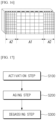
- FIG. 17 is a flowchart illustrating a secondary battery manufacturing method according to exemplary embodiments of the present invention.
- the secondary battery manufacturing method of the present invention includes an activation step S100, an aging step S200, and a degassing step S300.
- the activation step S100 the battery cell is activated by simultaneously charging and pressurizing the battery cell using the activation device described above.
- the electrode assembly is accommodated in the battery case, and once the injection of an electrolyte solution is completed, the battery cell in which the battery case is sealed is charged to a predetermined SOC, and an electrochemical reaction between the electrode active material and the electrolyte solution is performed to form a SEI (Solid Electrolyte Interface) layer, thereby activating the battery cell for use.
- the battery cell may be a pouch-type battery cell in which an electrode assembly and an electrolyte are embedded in a battery case of a laminate sheet including a resin layer and a metal layer.
- the battery When the secondary battery is activated, the battery is pressurized at the same time as charging in order to prevent gas generated during charging from being trapped inside the electrode assembly, and thus the internal gas moves out of the electrode assembly.
- a pressurization process is performed by using upper and lower pressing plates and multiple first and second elastic pressing members.
- Each of the first and second elastic pressing members includes an elastic member and a pressing block.
- the first and second elastic pressing members including the elastic member and the pressing block may uniformly press the entire secondary battery during the activation process of a pouch-type battery or a prismatic battery regardless of the flatness of the secondary battery.
- the activation process performed with uniform pressurization allows generated activated gas to be removed without local trapping, and thus a secondary battery in a uniformly charged state can be manufactured.
- the pressing blocks 112b, 122b may be formed in the same size.
- pressing blocks 212b, 222b pressurizing the first region A1 having a constant electrode thickness is formed in the first size
- pressing blocks 212b, 222b pressurizing the second region A2 in which the electrode becomes thin may be formed in the second size smaller than the first size.
- the pressing blocks 312b, 322b pressurizing the second region A2 may be formed in the second size smaller than the first size, and may gradually decrease in size toward the end of the secondary battery.
- An aging step is a process of aging the secondary battery under various conditions in order to accelerate the stabilization of the SEI film formed through the activation step.
- the aging step S200 may go through a room temperature aging that ages the secondary battery for a predetermined time under room temperature/normal pressure conditions, and depending on the purpose, a high temperature aging may be performed instead of the room temperature aging, and both room temperature aging and high temperature aging may be performed.
- the high temperature aging is a process of aging the battery in a high temperature environment, and it can accelerate the stabilization of the SEI film. High temperature aging and room temperature aging processes may be sequentially performed on the activated battery.
- the high temperature aging may be performed at a temperature of 50°C to 100°C, preferably 50°C to 80°C.
- the high temperature aging may be performed for 1 to 30 hours, preferably 2 to 24 hours.
- the room temperature aging may be performed at a temperature of 18°C to 28°C, specifically 19°C to 27°C, more specifically 20°C to 26°C, and even more specifically 21°C to 25°C. Room temperature aging may be performed for 12 to 120 hours, or for 18 to 72 hours.
- the degassing step S300 is a process of discharging oxygen gas generated during the activation and aging steps to the outside of the battery.
- the degassing step may be performed without limitation by a method commonly used in the battery field.
- the degassing step may include: a step of forming an opening by cutting a part of the gas pocket part or forming a through hole; a step of discharging gas inside the secondary battery to the outside of the secondary battery through the opening or the through hole; and a step of re-sealing the gas pocket part.
- the step of forming the opening or the through hole is a step of forming an opening or a through hole through which gas can be degassed in a partial region of the gas pocket part in order to discharge gas inside the sealed secondary battery to the outside.
- a part of the pouch may be cut, and in order to form the through hole, a piercing means capable of forming a hole in the pouch may be used. It is preferable that the position where the opening and the through hole are formed on the upper end of the gas pocket part.
- the step of discharging the internal gas to the outside is a step of degassing the gas containing oxygen present in the battery case to the outside through an opening or a through hole formed in the gas pocket part.
- the chamber in which the lithium secondary battery is accommodated may be in a vacuum state, and the internal gas of the secondary battery may be discharged to the outside to be removed.
- a pressurization process of the lithium secondary battery may be performed.
- the step of re-sealing the gas pocket part is a step of re-sealing the lithium secondary battery for an aging process or an additional charging process after a degassing process.
- the opening or the through hole can be removed by cutting a region of the gas pocket part including the opening or the through hole, and the gas pocket part can be sealed by sealing the cut surface.
Landscapes
- Engineering & Computer Science (AREA)
- Manufacturing & Machinery (AREA)
- Chemical & Material Sciences (AREA)
- Chemical Kinetics & Catalysis (AREA)
- Electrochemistry (AREA)
- General Chemical & Material Sciences (AREA)
- Secondary Cells (AREA)
Abstract
the secondary battery activation device according to the exemplary embodiment of the present invention includes:
an upper pressing unit including an upper pressing plate and first elastic pressing members formed in numbers on the lower surface of the upper pressing plate; and a lower pressing unit including a lower pressing plate formed to face the upper pressing plate and multiple second elastic pressing members formed on the upper surface of the lower pressing plate.
Description
- This application claims the benefit of priority based on
Korean Patent Application No. 10-2021-0162689 filed on November 23, 2021 - The present invention relates to a secondary battery activation device capable of effectively removing gas generated inside a secondary battery cell during a secondary battery activation process and a secondary battery manufacturing method using the same.
- As technology development and demand for mobile devices increase, the demand for batteries as an energy source is rapidly increasing, and accordingly, a lot of research is being conducted on batteries that can meet various needs.
- Typically, in terms of a battery shape, there is a high demand for prismatic secondary batteries and pouch-type secondary batteries that can be applied to products such as mobile phones with their thinness, and in terms of materials, there is a high demand for lithium secondary batteries such as lithium-ion batteries and lithium-ion polymer batteries, which have advantages such as high energy density, high discharge voltage, and output stability.
- In addition, secondary batteries are also classified according to the structure of the electrode assembly having a positive electrode/a separator/a negative electrode structure. Typically, a jelly-roll (wound type) type electrode assembly having a structure in which a long sheet-type positive electrodes and negative electrodes are wound with a separator interposed therebetween, a stack-type (layered type) electrode assembly in which multiple positive electrodes and negative electrodes cut in units of a predetermined size are stacked in order with a separator interposed therebetween, a stack-folding type electrode assembly having a structure of winding a bi-cell or a full cell in which positive electrodes and negative electrodes of a predetermined unit are layered with a separator interposed therebetween, etc. may be mentioned.
- Recently, a pouch-type battery having a structure in which a stack-type or stack-folding type electrode assembly is embedded in a pouch-type battery case of an aluminum laminate sheet has attracted much attention due to low manufacturing cost, small weight, and easy shape variation, and its usage is also gradually increasing.
- Most secondary batteries, including pouch-type batteries, go through a process of activating the battery by charging and discharging during the manufacturing process of the battery cell. To manufacture a final battery cell, gas generated during the activation process should be removed, and this is called a degassing process.
-
FIG. 1 is a cross-sectional view schematically illustrating a secondary battery activation device according to the prior art, andFIG. 2 and FIG. 3 are images showing results obtained by performing a high-temperature pressurization activation process with a secondary battery activation device according to the prior art. - Referring to
FIG. 1 , the secondary battery activation device according to the prior art is composed of a plate-shaped upper pressing plate 1 and a lowerpressing plate 2. A plate-shaped upper pressing plate 1 and lowerpressing plate 2 press both sides of the secondary battery B at a high temperature while being heated with the secondary battery B interposed therebetween, so that the generated gas by charging is removed at the interface between the electrodes to activate the secondary battery B. - However, when manufacturing the electrode constituting the secondary battery B, when the electrode material is coated in a slurry state, a slight flow phenomenon occurs until the end of the electrode is dried due to the fluidity of the slurry, and the thickness of the electrode becomes thin (a so-called sliding region of the electrode), thereby a difference in thickness occurs at the end of the electrode, resulting in an imbalance in the thickness of the secondary battery B (See C of
FIG. 1 for reference). - In this state, when the activation process is performed with the secondary battery activation device of
FIG. 1 , as illustrated inFIG. 2 , the gas generated by the activation process is gathered at the end of the secondary battery B to be located at the interface of each electrode. But the pressing force of thepressing plates 1, 2 is not transmitted to the part where the thickness of the secondary battery B becomes thin (C inFIG. 1 ), so that a phenomenon in which gas becomes trapped occur as shown inFIG. 3 . This gas trap phenomenon has a problem of causing a non-uniform charging. - The present invention is directed to provide a secondary battery activation device in which gas generated during an activation process is not locally trapped in a cell by uniformly pressurizing the secondary battery cell during the secondary battery activation process, even if there is a part in the secondary battery cell that is locally thin, and a secondary battery manufacturing method using the same.
- The secondary battery activation device according to an exemplary embodiment of the present invention includes:
an upper pressing unit including an upper pressing plate and multiple first elastic pressing members formed on the lower surface of the upper pressing plate; and a lower pressing unit including a lower pressing plate formed to face the upper pressing plate and multiple second elastic pressing members formed on the upper surface of the lower pressing plate. - In the secondary battery activation device according to an exemplary embodiment of the present invention, the first elastic pressing member includes an elastic member and a pressing block, an upper end of the elastic member is fixed to the lower surface of the upper pressing plate, and a lower end of the elastic member is fixed to the pressing block. In addition, the second elastic pressing member includes an elastic member and a pressing block, a lower end of the elastic member is fixed to the upper surface of the lower pressing plate, and an upper end of the elastic member is fixed to the pressing block.
- In the secondary battery activation device according to an exemplary embodiment of the present invention, the elastic member may be a spring.
- In the secondary battery activation device according to an exemplary embodiment of the present invention, the pressing block may have an elastic surface formed on a surface that presses a secondary battery.
- In the secondary battery activation device according to an exemplary embodiment of the present invention, each of the pressing blocks constituting the first and the second elastic pressing members may be formed to have the same size in the entire pressing region for pressing the secondary battery.
- In the secondary battery activation device according to an exemplary embodiment of the present invention, among the pressing blocks constituting the first and the second elastic pressing members, pressing blocks for pressing the first region in which the electrode thickness of the secondary battery is constant may be formed in a first size, and pressing blocks for pressing the second region in which the electrode thickness of the secondary battery becomes thin may be formed in a second size, which is smaller than the first size.
- In the secondary battery activation device according to an exemplary embodiment of the present invention, pressing blocks for pressing the second region may be formed to have a second size, which is smaller than the first size, and may be formed to become gradually smaller toward the end of the secondary battery.
- In the secondary battery activation device according to an exemplary embodiment of the present invention, the pressing blocks may be formed in a stripe shape.
- In the secondary battery activation device according to an exemplary embodiment of the present invention, the pressing blocks may be formed in a grid shape.
- A secondary battery manufacturing method is performed by using the above-described secondary battery activation device in the activation step of the secondary battery.
- Other specific details of the embodiments according to various aspects of the present invention are included in the detailed description below.
- According to an exemplary embodiment of the present invention, since the entire surface of the secondary battery cell is uniformly pressed, even if there is a part that is locally thin due to uneven thickness of the secondary battery cell, there is an effect of preventing gas generated inside the secondary battery cell from being trapped inside the electrode assembly during the secondary battery activation process.
-
-
FIG. 1 is a cross-sectional view schematically illustrating a secondary battery activation device according to the prior art. -
FIG. 2 and FIG. 3 are images showing results obtained by performing a high-temperature pressurization activation process with a secondary battery activation device according to the prior art. -
FIG. 4 is a cross-sectional view schematically illustrating a secondary battery activation device according to the first embodiment of the present invention. -
FIG. 5 is a diagram illustrating a pressing block formed in a stripe shape. -
FIG. 6 is a diagram illustrating a pressing block formed in a grid shape. -
FIG. 7 is a cross-sectional view schematically illustrating a secondary battery activation device according to the second embodiment of the present invention. -
FIG. 8 to FIG. 11 are diagrams illustrating pressing blocks formed in various shapes. -
FIG. 12 is a cross-sectional view schematically illustrating a secondary battery activation device according to the third embodiment of the present invention. -
FIG. 13 to FIG. 16 are diagrams illustrating pressing blocks formed in various shapes. -
FIG. 17 is a flowchart illustrating a secondary battery manufacturing method using a secondary battery activation device according to the embodiments of the present invention. -
- 100, 200, 300: SECONDARY BATTERY ACTIVATION DEVICE
- 110, 210, 310: UPPER PRESSING UNIT
- 120, 220, 320: LOWER PRESSING UNIT
- 111, 211, 311: UPPER PRESSING PLATE
- 121, 221, 321: LOWER PRESSING PLATE
- 112, 212, 312: FIRST ELASTIC PRESSING MEMBER
- 122, 222, 322: SECOND ELASTIC PRESSING MEMBER
- 112a, 122a, 212a, 222a, 312a, 322a: ELASTIC MEMBER
- 112b, 122b, 212b, 222b, 312b, 322b: PRESSING BLOCK
- Since the present invention can make various changes and can have various examples, specific embodiments are illustrated in the drawings and described in detail in the description. However, it is not intended to limit the present invention to a specific embodiment, and it should be understood to include all modifications, equivalents, or substitutes included in the spirit and technical scope of the present invention.
- The terms used in the present invention are only used to describe specific embodiments, and are not intended to limit the present invention. Singular expressions include plural expressions unless the context clearly dictates otherwise. The terms "comprise" or "have" used herein designate the presence of characteristics, numbers, steps, actions, components or elements described in the specification or a combination thereof, and it should be understood that the possibility of the presence or addition of one or more other characteristics, numbers, steps, actions, components, elements or a combination thereof is not excluded in advance. Hereinafter, a secondary battery activation device according to an exemplary embodiment of the present invention and a secondary battery manufacturing method using the same will be described with reference to the diagrams.
- First, the secondary battery activation device according to the first embodiment of the present invention will be described by referring to
FIG. 4 to FIG. 6. FIG. 4 is a cross-sectional view schematically illustrating a secondary battery activation device according to the first embodiment of the present invention,FIG. 5 is a diagram illustrating a pressing block formed in a stripe shape, andFIG. 6 is a diagram illustrating a pressing block formed in a grid shape. - As shown in
FIG. 4 , the secondarybattery activation device 100 according to the first embodiment of the present invention includes an upperpressing unit 110 and a lowerpressing unit 120. The upperpressing unit 110 presses the upper surface of the secondary battery B at a high temperature, and the lowerpressing unit 120 presses the lower surface of the secondary battery B at a high temperature. - The upper
pressing unit 110 includes an upper pressing plate 111 and multiple first elastic pressingmembers 112. - The upper pressing plate 111 may be formed in a predetermined shape, for example, a rectangular plate shape, and multiple first elastic pressing
members 112 may be formed on the lower surface of the upper pressing plate 111 at equal spacings. Each of the first elastic pressingmembers 112 includes anelastic member 112a and apressing block 112b. - The
elastic member 112a may be a material capable of contracting/expanding by an external force, such as a spring or a synthetic rubber. In the diagram, it is exemplified that theelastic member 112a is a spring. The upper end of theelastic member 112a is fixed to the lower surface of the upper pressing plate 111, and the lower end of theelastic member 112a is fixed to thepressing block 112b. - As illustrated in
FIG. 5 , thepressing block 112b may be formed in a stripe shape having a predetermined width and length. Alternatively, as illustrated inFIG. 6 , thepressing block 112b may be formed in a grid shape having a predetermined area. - When the
pressing block 112b is formed in a stripe shape as shown inFIG. 5 , there is an advantage in that manufacturing is relatively easy. Meanwhile, when thepressing block 112b is formed in a grid shape as shown inFIG. 6 , although manufacturing is relatively complicated, there is an advantage in that uniform pressurization is possible even with minute changes in the thickness of the secondary battery B. - The
pressing block 112b is formed of a solid material as a whole, but an elastic surface made of rubber or the like having a certain hardness may be formed on the surface on which the secondary battery B is pressed. The elastic surface prevents the surface of the secondary battery B from being damaged by the pressure of thepressing block 112b. - The lower
pressing unit 120 includes a lowerpressing plate 121 facing the upper pressing plate 111 and multiple second elastic pressingmembers 122. - The lower
pressing plate 121 may be formed in a shape corresponding to the upper pressing plate 111, and multiple second elastic pressingmembers 122 may be formed at equal spacings on the upper surface of the lowerpressing plate 121. Each of the second elastic pressingmembers 122 includes anelastic member 122a and apressing block 122b. - Since the
elastic member 122a and thepressing block 122b are substantially the same as the aforementionedelastic member 112a and thepressing block 112b, a repeated description thereof will be omitted. - Based on the secondary battery activation device according to the first embodiment of the present invention configured as described above, in the activation process of a pouch-type battery or a prismatic battery, the secondary battery can be uniformly pressed as a whole regardless of the flatness of the secondary battery.
- In particular, even if there is a locally thin part in the thickness of the secondary battery, pressure can be uniformly applied by the spring elastic body, enabling a more uniform activation reaction than in the prior art.
- The activation process performed with uniform pressure allows the generated activated gas to be removed without local trapping, and thus a secondary battery in a uniformly charged state can be manufactured.
- Next, a secondary battery activation device according to the second embodiment of the present invention will be described with reference to
FIG. 7 to FIG. 11 .FIG. 7 is a cross-sectional view schematically illustrating a secondary battery activation device according to the second embodiment of the present invention, andFIG. 8 to FIG. 11 are diagrams illustrating pressing blocks formed in various shapes. - As shown in
FIG. 7 , the secondarybattery activation device 200 according to the second embodiment of the present invention includes an upperpressing unit 210 and a lowerpressing unit 220. In this embodiment, except for thepressing blocks - In the present embodiment, the
pressing blocks pressing blocks pressing blocks - The smaller the sizes of the
pressing blocks pressing blocks pressing blocks - In this way, by changing the size of the
pressing blocks pressing blocks elastic members pressing blocks elastic members -
FIG. 8 illustrates that thepressing blocks FIG. 9 illustrates that they are formed in a grid shape with a predetermined area. - When the
pressing blocks FIG. 8 , there is an advantage in that manufacturing is relatively easy. Meanwhile, when thepressing blocks FIG. 9 , although manufacturing is relatively complicated, there is an advantage in that uniform pressurization is possible even with minute thickness changes over the entire area of the secondary battery B. -
FIG. 10 and FIG. 11 show the arrangement of thepressing blocks FIG. 10 shows pressing blocks FIG. 11 shows pressing blocks - Referring to
FIG. 10 and FIG. 11 , since the second region is formed on both sides of a secondary battery having electrode leads formed on both sides, a second size pressing block is formed on both sides and a first size pressing block is formed in the center. - Next, a secondary battery activation device according to the third embodiment of the present invention will be described with reference to
FIG. 12 to FIG. 16 .FIG. 12 is a cross-sectional view schematically illustrating a secondary battery activation device according to the third embodiment of the present invention, andFIG. 13 to FIG. 16 are diagrams showing pressing blocks formed in various shapes. - As shown in
FIG. 12 , the secondarybattery activation device 300 according to the third embodiment of the present invention includes an upperpressing unit 310 and a lowerpressing unit 320. In this embodiment, except for thepressing blocks - In the present embodiment, the
pressing blocks pressing blocks pressing blocks - The electrode thickness in the second region does not decrease at a constant rate, and the decrease rate in the electrode thickness may increase toward the end of the secondary battery B. Therefore, in the present embodiment, the size of the
pressing blocks -
FIG. 13 illustrates that thepressing blocks FIG. 14 illustrates that they are formed in a grid shape with a predetermined area. - When the
pressing blocks FIG. 13 , there is an advantage in that manufacturing is relatively easy. On the other hand, when thepressing blocks FIG. 14 , although manufacturing is relatively complicated, there is an advantage in that uniform pressurization is possible even with minute thickness changes over the entire area of the secondary battery B. -
FIG. 15 andFIG. 16 show the arrangement of thepressing blocks FIG. 15 shows pressing blocks FIG. 16 shows pressing blocks - Referring to
FIG. 15 andFIG. 16 , since the secondary battery having electrode leads formed on both sides is formed with a second region on both sides, a first size pressing blocks are formed in the center, and pressing blocks having a second size smaller than the first size, which gradually become smaller toward the end, are formed on both sides. - Next, the secondary battery manufacturing method of the present invention will be described.
- The secondary battery manufacturing method according to the present invention uses the above-described activation device in the step of activating the secondary battery.
-
FIG. 17 is a flowchart illustrating a secondary battery manufacturing method according to exemplary embodiments of the present invention. Referring toFIG. 17 , the secondary battery manufacturing method of the present invention includes an activation step S100, an aging step S200, and a degassing step S300. In the activation step S100, the battery cell is activated by simultaneously charging and pressurizing the battery cell using the activation device described above. - In the activation step S100, the electrode assembly is accommodated in the battery case, and once the injection of an electrolyte solution is completed, the battery cell in which the battery case is sealed is charged to a predetermined SOC, and an electrochemical reaction between the electrode active material and the electrolyte solution is performed to form a SEI (Solid Electrolyte Interface) layer, thereby activating the battery cell for use. The battery cell may be a pouch-type battery cell in which an electrode assembly and an electrolyte are embedded in a battery case of a laminate sheet including a resin layer and a metal layer.
- When the secondary battery is activated, the battery is pressurized at the same time as charging in order to prevent gas generated during charging from being trapped inside the electrode assembly, and thus the internal gas moves out of the electrode assembly.
- In the present invention, for such pressurization, a pressurization process is performed by using upper and lower pressing plates and multiple first and second elastic pressing members. Each of the first and second elastic pressing members includes an elastic member and a pressing block.
- As described above, the first and second elastic pressing members including the elastic member and the pressing block may uniformly press the entire secondary battery during the activation process of a pouch-type battery or a prismatic battery regardless of the flatness of the secondary battery. The activation process performed with uniform pressurization allows generated activated gas to be removed without local trapping, and thus a secondary battery in a uniformly charged state can be manufactured.
- As shown in
FIG. 4 to FIG. 6 , thepressing blocks FIG. 7 to FIG. 11 , pressingblocks blocks FIG. 12 to FIG. 16 , thepressing blocks - An aging step is a process of aging the secondary battery under various conditions in order to accelerate the stabilization of the SEI film formed through the activation step.
- The aging step S200 may go through a room temperature aging that ages the secondary battery for a predetermined time under room temperature/normal pressure conditions, and depending on the purpose, a high temperature aging may be performed instead of the room temperature aging, and both room temperature aging and high temperature aging may be performed. The high temperature aging is a process of aging the battery in a high temperature environment, and it can accelerate the stabilization of the SEI film. High temperature aging and room temperature aging processes may be sequentially performed on the activated battery.
- In one specific example, the high temperature aging may be performed at a temperature of 50°C to 100°C, preferably 50°C to 80°C. The high temperature aging may be performed for 1 to 30 hours, preferably 2 to 24 hours.
- In one specific example, the room temperature aging may be performed at a temperature of 18°C to 28°C, specifically 19°C to 27°C, more specifically 20°C to 26°C, and even more specifically 21°C to 25°C. Room temperature aging may be performed for 12 to 120 hours, or for 18 to 72 hours.
- The degassing step S300 is a process of discharging oxygen gas generated during the activation and aging steps to the outside of the battery. The degassing step may be performed without limitation by a method commonly used in the battery field.
- In one specific example, the degassing step may include: a step of forming an opening by cutting a part of the gas pocket part or forming a through hole; a step of discharging gas inside the secondary battery to the outside of the secondary battery through the opening or the through hole; and a step of re-sealing the gas pocket part.
- The step of forming the opening or the through hole is a step of forming an opening or a through hole through which gas can be degassed in a partial region of the gas pocket part in order to discharge gas inside the sealed secondary battery to the outside. In order to form the opening, a part of the pouch may be cut, and in order to form the through hole, a piercing means capable of forming a hole in the pouch may be used. It is preferable that the position where the opening and the through hole are formed on the upper end of the gas pocket part.
- The step of discharging the internal gas to the outside is a step of degassing the gas containing oxygen present in the battery case to the outside through an opening or a through hole formed in the gas pocket part. Here, the chamber in which the lithium secondary battery is accommodated may be in a vacuum state, and the internal gas of the secondary battery may be discharged to the outside to be removed. In addition, during the degassing process, a pressurization process of the lithium secondary battery may be performed.
- The step of re-sealing the gas pocket part is a step of re-sealing the lithium secondary battery for an aging process or an additional charging process after a degassing process. In one specific example, the opening or the through hole can be removed by cutting a region of the gas pocket part including the opening or the through hole, and the gas pocket part can be sealed by sealing the cut surface.
- As above, the present invention has been described with reference to exemplary embodiments, but it should be understood by those skilled in the art that the present invention can be variously modified and changed by adding, changing, or deleting components within the scope that does not depart from the spirit of the present invention described in the accompanying claims, which will also be said to be included within the scope of the present invention.
Claims (10)
- A secondary battery activation device, comprising:an upper pressing unit comprising an upper pressing plate and multiple first elastic pressing members formed on the lower surface of the upper pressing plate; anda lower pressing unit comprising a lower pressing plate formed to face the upper pressing plate and multiple second elastic pressing members formed on the upper surface of the lower pressing plate.
- The secondary battery activation device of claim 1, whereinthe first elastic pressing member comprises an elastic member and a pressing block, an upper end of the elastic member is fixed to the lower surface of the upper pressing plate, and a lower end of the elastic member is fixed to the pressing block.the second elastic pressing member comprises an elastic member and a pressing block, a lower end of the elastic member is fixed to the upper surface of the lower pressing plate, and an upper end of the elastic member is fixed to the pressing block.
- The secondary battery activation device of claim 2, wherein
the elastic member is a spring. - The secondary battery activation device of claim 2, wherein
the pressing block has an elastic surface formed on a surface that presses a secondary battery. - The secondary battery activation device of claim 2, wherein
each of the pressing blocks constituting the first and the second elastic pressing members is formed to have the same size in the entire pressing region for pressing the secondary battery. - The secondary battery activation device of claim 2, whereinamong the pressing blocks constituting the first and the second elastic pressing members,pressing blocks for pressing the first region in which the electrode thickness of the secondary battery is constant are formed in a first size, and pressing blocks for pressing the second region in which the electrode thickness of the secondary battery becomes thin are formed in a second size, which is smaller than the first size.
- The secondary battery activation device of claim 6, wherein
pressing blocks for pressing the second region are formed to have a second size, which is smaller than the first size, and are formed to become gradually smaller toward the end of the secondary battery. - The secondary battery activation device of any one of claim 2 to claim 7, wherein
the pressing blocks are formed in a stripe shape. - The secondary battery activation device of any one of claim 2 to claim 7, wherein
the pressing blocks are formed in a grid shape. - A secondary battery manufacturing method uses the secondary battery activation device of any one of claim 1 to claim 9 in the activation step of the secondary battery.
Applications Claiming Priority (2)
| Application Number | Priority Date | Filing Date | Title |
|---|---|---|---|
| KR1020210162689A KR20230075963A (en) | 2021-11-23 | 2021-11-23 | Secondary battery activation device and secondary battery manufacturing method using same |
| PCT/KR2022/018560 WO2023096323A1 (en) | 2021-11-23 | 2022-11-23 | Secondary battery activating apparatus and secondary battery manufacturing method using same |
Publications (2)
| Publication Number | Publication Date |
|---|---|
| EP4258401A1 true EP4258401A1 (en) | 2023-10-11 |
| EP4258401A4 EP4258401A4 (en) | 2024-11-27 |
Family
ID=86540019
Family Applications (1)
| Application Number | Title | Priority Date | Filing Date |
|---|---|---|---|
| EP22899005.7A Pending EP4258401A4 (en) | 2021-11-23 | 2022-11-23 | SECONDARY BATTERY ACTIVATION DEVICE AND SECONDARY BATTERY MANUFACTURING METHOD THEREOF |
Country Status (6)
| Country | Link |
|---|---|
| US (1) | US20240072289A1 (en) |
| EP (1) | EP4258401A4 (en) |
| JP (2) | JP2024503436A (en) |
| KR (1) | KR20230075963A (en) |
| CN (1) | CN116724433A (en) |
| WO (1) | WO2023096323A1 (en) |
Families Citing this family (3)
| Publication number | Priority date | Publication date | Assignee | Title |
|---|---|---|---|---|
| WO2025095378A1 (en) * | 2023-10-30 | 2025-05-08 | 주식회사 엘지에너지솔루션 | Battery cell pressing pad and battery cell pressing apparatus comprising same |
| CN117199494B (en) * | 2023-11-08 | 2024-04-12 | 宁德时代新能源科技股份有限公司 | Battery pressurizing device and battery production system |
| WO2026071564A1 (en) * | 2024-09-30 | 2026-04-02 | 주식회사 엘지에너지솔루션 | Pouch-type battery cell pressing member, battery module including same, and pouch-type battery cell pressing method using same |
Family Cites Families (10)
| Publication number | Priority date | Publication date | Assignee | Title |
|---|---|---|---|---|
| JP3521083B2 (en) * | 2002-07-25 | 2004-04-19 | 株式会社根本精機 | Pressurizing device for sheet pressurized object |
| KR20130044776A (en) * | 2011-10-24 | 2013-05-03 | 에스케이이노베이션 주식회사 | Degassing apparatus for battery cell and method of the same |
| KR101505722B1 (en) * | 2012-04-09 | 2015-03-25 | 주식회사 엘지화학 | Lithium secondary battery comprising elastic clip device and method for preparation the same |
| JP2013223870A (en) * | 2012-04-20 | 2013-10-31 | Toyota Motor Corp | Device and method for manufacturing secondary battery |
| JP2014011066A (en) * | 2012-06-29 | 2014-01-20 | Toyota Motor Corp | Initial charging method of battery, charging device, and battery |
| KR102004295B1 (en) * | 2013-10-15 | 2019-07-29 | 에스케이이노베이션 주식회사 | Manufacturing method of secondary battery |
| KR101650858B1 (en) | 2014-03-13 | 2016-08-24 | 주식회사 엘지화학 | Method for Manufacturing Battery Cell and Device for Eliminating Gas from Battery Cell |
| KR101949973B1 (en) * | 2016-04-15 | 2019-02-20 | 주식회사 엘지화학 | Electrolyte impregnation apparatus |
| KR102188712B1 (en) * | 2016-07-14 | 2020-12-08 | 주식회사 엘지화학 | Tray for activating of battery cell |
| KR102689714B1 (en) * | 2018-11-02 | 2024-07-30 | 주식회사 엘지에너지솔루션 | Pressing jig, device for charging and discharging including the same, and method for charging and discharging battery cell using the same |
-
2021
- 2021-11-23 KR KR1020210162689A patent/KR20230075963A/en not_active Ceased
-
2022
- 2022-11-23 US US18/272,038 patent/US20240072289A1/en active Pending
- 2022-11-23 EP EP22899005.7A patent/EP4258401A4/en active Pending
- 2022-11-23 JP JP2023542565A patent/JP2024503436A/en active Pending
- 2022-11-23 WO PCT/KR2022/018560 patent/WO2023096323A1/en not_active Ceased
- 2022-11-23 CN CN202280010950.5A patent/CN116724433A/en active Pending
-
2025
- 2025-06-24 JP JP2025106164A patent/JP2025134925A/en active Pending
Also Published As
| Publication number | Publication date |
|---|---|
| JP2024503436A (en) | 2024-01-25 |
| CN116724433A (en) | 2023-09-08 |
| KR20230075963A (en) | 2023-05-31 |
| WO2023096323A1 (en) | 2023-06-01 |
| US20240072289A1 (en) | 2024-02-29 |
| EP4258401A4 (en) | 2024-11-27 |
| JP2025134925A (en) | 2025-09-17 |
Similar Documents
| Publication | Publication Date | Title |
|---|---|---|
| EP4258401A1 (en) | Secondary battery activating apparatus and secondary battery manufacturing method using same | |
| US20250336912A1 (en) | Method of Manufacturing All-Solid-State Battery and All-Solid-State Battery Manufactured Using the Same | |
| US11949062B2 (en) | Pressing jig for removing gas trap and method for manufacturing secondary battery using same | |
| KR102135266B1 (en) | Apparatus and method for manufacturing battery cell | |
| EP3637492A1 (en) | Pouch-type secondary battery sealing block for preventing cracks, pouch-type battery case manufactured by using same, and sealing method for pouch-type battery case | |
| US12531264B2 (en) | Sequential pressure formation jig and formation method using same | |
| US11876185B2 (en) | Method for manufacturing secondary battery and secondary battery | |
| KR20150050223A (en) | Pressure tray and Pressure jig applied for the same | |
| US12500260B2 (en) | Pressing jig with a gradient hardness pressing pad for a battery cell and a degassing method of battery cell using the same | |
| KR102180946B1 (en) | Buffer Plate for Uniform SEI Formation, and Battery Manufacturing Method thereof | |
| KR20190078221A (en) | Lithium rechargeable battery | |
| KR100646508B1 (en) | Separator and secondary battery having same | |
| KR20230071075A (en) | Formation method for secondary battery | |
| US11631900B2 (en) | Lithium-ion battery formation process | |
| EP4503213A1 (en) | Prismatic secondary battery manufacturing method | |
| EP4693576A1 (en) | Battery cell manufacturing method | |
| KR20250077368A (en) | Battery cell manufacturing method | |
| KR20210128733A (en) | Method for Manufacturing Battery Cell and Device for the same | |
| JP2026508220A (en) | Battery cell activation device and battery cell activation method using the same | |
| KR20250089060A (en) | Battery cell manufacturing method |
Legal Events
| Date | Code | Title | Description |
|---|---|---|---|
| STAA | Information on the status of an ep patent application or granted ep patent |
Free format text: STATUS: THE INTERNATIONAL PUBLICATION HAS BEEN MADE |
|
| PUAI | Public reference made under article 153(3) epc to a published international application that has entered the european phase |
Free format text: ORIGINAL CODE: 0009012 |
|
| STAA | Information on the status of an ep patent application or granted ep patent |
Free format text: STATUS: REQUEST FOR EXAMINATION WAS MADE |
|
| 17P | Request for examination filed |
Effective date: 20230707 |
|
| AK | Designated contracting states |
Kind code of ref document: A1 Designated state(s): AL AT BE BG CH CY CZ DE DK EE ES FI FR GB GR HR HU IE IS IT LI LT LU LV MC ME MK MT NL NO PL PT RO RS SE SI SK SM TR |
|
| A4 | Supplementary search report drawn up and despatched |
Effective date: 20241029 |
|
| RIC1 | Information provided on ipc code assigned before grant |
Ipc: H01M 10/44 20060101ALI20241023BHEP Ipc: H01M 10/058 20100101ALI20241023BHEP Ipc: H01M 10/04 20060101AFI20241023BHEP |
|
| DAV | Request for validation of the european patent (deleted) | ||
| DAX | Request for extension of the european patent (deleted) | ||
| STAA | Information on the status of an ep patent application or granted ep patent |
Free format text: STATUS: EXAMINATION IS IN PROGRESS |
|
| 17Q | First examination report despatched |
Effective date: 20250923 |