EP4258299A1 - Magnet holding device, magnetization device, and magnetizing method - Google Patents
Magnet holding device, magnetization device, and magnetizing method Download PDFInfo
- Publication number
- EP4258299A1 EP4258299A1 EP23165904.6A EP23165904A EP4258299A1 EP 4258299 A1 EP4258299 A1 EP 4258299A1 EP 23165904 A EP23165904 A EP 23165904A EP 4258299 A1 EP4258299 A1 EP 4258299A1
- Authority
- EP
- European Patent Office
- Prior art keywords
- ring
- shaped portion
- magnet
- magnetization
- holding device
- Prior art date
- Legal status (The legal status is an assumption and is not a legal conclusion. Google has not performed a legal analysis and makes no representation as to the accuracy of the status listed.)
- Pending
Links
Images






Classifications
-
- H—ELECTRICITY
- H01—ELECTRIC ELEMENTS
- H01F—MAGNETS; INDUCTANCES; TRANSFORMERS; SELECTION OF MATERIALS FOR THEIR MAGNETIC PROPERTIES
- H01F7/00—Magnets
-
- H—ELECTRICITY
- H01—ELECTRIC ELEMENTS
- H01F—MAGNETS; INDUCTANCES; TRANSFORMERS; SELECTION OF MATERIALS FOR THEIR MAGNETIC PROPERTIES
- H01F7/00—Magnets
- H01F7/02—Permanent magnets [PM]
- H01F7/0205—Magnetic circuits with PM in general
- H01F7/0221—Mounting means for PM, supporting, coating, encapsulating PM
-
- H—ELECTRICITY
- H01—ELECTRIC ELEMENTS
- H01F—MAGNETS; INDUCTANCES; TRANSFORMERS; SELECTION OF MATERIALS FOR THEIR MAGNETIC PROPERTIES
- H01F7/00—Magnets
- H01F7/02—Permanent magnets [PM]
- H01F7/0273—Magnetic circuits with PM for magnetic field generation
-
- H—ELECTRICITY
- H01—ELECTRIC ELEMENTS
- H01F—MAGNETS; INDUCTANCES; TRANSFORMERS; SELECTION OF MATERIALS FOR THEIR MAGNETIC PROPERTIES
- H01F13/00—Apparatus or processes for magnetising or demagnetising
-
- H—ELECTRICITY
- H01—ELECTRIC ELEMENTS
- H01F—MAGNETS; INDUCTANCES; TRANSFORMERS; SELECTION OF MATERIALS FOR THEIR MAGNETIC PROPERTIES
- H01F13/00—Apparatus or processes for magnetising or demagnetising
- H01F13/003—Methods and devices for magnetising permanent magnets
-
- H—ELECTRICITY
- H01—ELECTRIC ELEMENTS
- H01F—MAGNETS; INDUCTANCES; TRANSFORMERS; SELECTION OF MATERIALS FOR THEIR MAGNETIC PROPERTIES
- H01F7/00—Magnets
- H01F7/02—Permanent magnets [PM]
Definitions
- a measurement by magnetism can be employed for detecting wall thinning of a pipe caused by corrosion or the like.
- the pipe is magnetized, and its magnetic-flux density before the wall thinning is measured in advance.
- the magnetic-flux density around the pipe is measured again, and the wall thinning of the pipe can be detected based on a change in the magnetic-flux density.
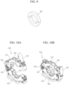
- FIG. 9 illustrates an exemplary configuration of a magnet M1 used in the measuring method.
- the magnet M1 is constituted of two half-doughnut shaped components.
- magnets having various configurations are required to be prepared.
- the magnet needs to be remade for each pipe, and it is difficult to flexibly change the configuration of the magnet.
- the present invention provides a magnetization device appropriate for various magnetization requirements.
- the present invention provides a magnet holding device and a magnetizing method related to the magnetization device.
- the magnet has a columnar shape, and a plurality of the magnets are arrangeable along a circumferential direction of the ring-shaped portion.
- a magnetization amount by the magnets is changeable by changing a number of the magnets.
- the open/close mechanism includes a coupling component disposed in both ends in the circumferential direction of the ring-shaped portion.
- One example of a magnetization device according to the present invention comprises the above-described magnet holding device and a magnet to be arranged in the magnet holding device.
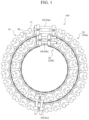
- FIG. 1 illustrates an exemplary configuration of a magnetization device 100 according to Embodiment 1 of the present invention.
- FIG. 2 is a drawing of the magnetization device 100 viewed from an angle different from that of FIG. 1 .
- the magnet holding device 10 includes a ring-shaped portion 20 that is openable/closable.
- the ring-shaped portion 20 is constituted of two layers, and includes an outer ring-shaped portion 20a and an inner ring-shaped portion 20b.
- the ring-shaped portion 20 includes a plurality of unit components 11, and is configured by the respective unit components 11 being coupled in a ring shape.
- the unit components 11 can each hold the magnet M.
- the magnet M is arrangeable in the ring-shaped portion 20, and particularly, a plurality of the magnets M are arrangeable along a circumferential direction of the ring-shaped portion 20.
- a "circumferential direction,” a “radial direction,” and an “axial direction” respectively corresponds to a circumferential direction, a radial direction, and an axial direction of a circular ring when the ring-shaped portion 20 is coupled so as to form the circular ring.
- these directions are appropriately definable.
- a direction perpendicular to the planar surface can be assumed to be the axial direction, and the radial direction and the circumferential direction can be defined with a predetermined position (a point inside the ring-shaped portion 20, for example) on the planar surface as reference.
- the magnet holding device 10 includes an open/close mechanism.
- the open/close mechanism includes coupling components 30 (more precisely, in the present embodiment, at least one of the coupling components 30 works as the open/close mechanism).
- the coupling component 30 is disposed on both ends in the circumferential direction of the ring-shaped portion 20, and is configured to be able to keep the ring-shaped portion 20 in a closed state.
- both ends in the circumferential direction of the outer ring-shaped portion 20a are coupled and fixed by a coupling component 30a, and thereby the outer ring-shaped portion 20a is closed.
- both ends in the circumferential direction of the inner ring-shaped portion 20b are coupled and fixed by a coupling component 30b, and thereby the inner ring-shaped portion 20b is closed.
- the coupling component 30 may have functions besides as the open/close mechanism.
- a coupling component 30c couples and fixes the outer ring-shaped portion 20a and the inner ring-shaped portion 20b with one another.
- the coupling component 30a and the coupling component 30b as the open/close mechanism, and the coupling component 30c for coupling the plurality of ring-shaped portions with one another are coupling components having the same structure in the present embodiment
- the coupling component 30a, the coupling component 30b, and the coupling component 30c may be coupling components having different structures. That is, the coupling in the circumferential direction and the coupling in the radial direction of the ring-shaped portion can be implemented by coupling components having different structures.
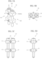
- FIG. 3A to FIG. 3D illustrate exemplary configurations of the unit component 11.
- FIG. 3A is a perspective view
- FIG. 3B is a drawing (top view) of FIG. 3A viewed in the IIIB-direction
- FIG. 3C is a drawing (front view) of FIG. 3A viewed in the IIIC-direction
- FIG. 3D is a drawing (side view) of FIG. 3A viewed in the IIID-direction.
- the unit component 11 includes a pedestal 12, a fixed component 13, a hinge 14, and a fixation screw 15.
- the pedestal 12, the fixed component 13, the hinge 14, and the fixation screw 15 are constituted of a non-magnetic body, for example, and as a specific example, they are constituted of stainless steel.
- the fixation screw 15 fixes the pedestal 12 and the fixed component 13, and thereby the magnet M is fixed between the pedestal 12 and the fixed component 13.
- a magnetization direction of the magnet M can be an axial direction of the column. However, it is preferable for the magnetization direction of the magnet M to coincide with the axial direction of the ring-shaped portion 20.
- FIG. 4 A coupling of adjacent unit components 11 will be described using FIG. 4 .
- the unit component 11 is rotatably coupled to another adjacent unit component 11 by the hinge 14.
- connecting holes 14a as illustrated in FIG. 3A and FIG. 3B are formed in the hinge 14, and coupling screws 16 are inserted through these connecting holes 14a.
- connecting holes 12a illustrated in FIG. 3A are formed in the pedestal 12.
- FIG. 3D two of each of the connecting hole 14a and the connecting hole 12a are presented. However, four of each of the connecting hole 14a and the connecting hole 12a including those that are in positions not presented in FIG. 3A to FIG. 3D are disposed. That is, while the connecting holes 14a and the connecting holes12a in positions where the hinge 14 and the pedestal 12 overlap are hidden and cannot be seen in FIG. 3A to FIG. 3D , as illustrated in FIG. 3C , the coupling screws 16 are used to fasten and fix the hinge 14 and the pedestal 12.
- FIG. 5A to FIG. 5D illustrate exemplary configurations of the coupling component 30.
- FIG. 5A is a perspective view
- FIG. 5B is a drawing (top view) of FIG. 5A viewed in a VB direction
- FIG. 5C is a drawing (front view) of FIG. 5A viewed in a VC-direction
- FIG. 5D is a drawing (side view) of FIG. 5A viewed in a VD-direction.
- the coupling component 30 includes two coupling screws 31, two supporting members 32, and two opening/closing screws 33.
- the entire coupling component 30 is constituted of a non-magnetic body, for example, and as a specific example, it is constituted of stainless steel.
- the respective opening/closing screws 33 are screwed with the supporting members 32, and relatively fix these supporting members 32.
- a coupling screw 31 is insertable through the supporting member 32.
- a connecting hole 13a is formed in the fixed component 13 of the unit component 11, and the coupling screw 31 can be screwed with the connecting hole 13a.
- Two coupling screws 31 are each fastened to a different unit component 11, and thereby those unit components 11 are coupled to one another.
- the supporting member 32 (supporting member 32a) that is closer to the heads of the opening/closing screws 33 of the two supporting members 32 may include through holes (what is called clearance holes) for the opening/closing screws 33 to be inserted through instead of screw holes that are screwed with the opening/closing screws 33.
- FIG. 6 is a flowchart describing the magnetizing method according to the present embodiment.
- FIG. 7 is a drawing of a halfway state in the magnetizing method in FIG. 6 . As illustrated in FIG. 7 , it is preferable to preliminarily leave a marking 201 indicating a range that is to be magnetized on an object 200 such as a pipe.
- the magnetizing method according to the present embodiment includes each step indicated in FIG. 6 .
- a user of the magnetization device 100 arranges the object 200 in the ring-shaped portion 20 in a state where the ring-shaped portion 20 is open (Step S1, arranging step).
- the object 200 is a pipe, for example, and is the target of a magnetization effect of the magnetization device 100.
- Step S2 attaches the magnetization device 100 to the object 200 by closing the ring-shaped portion 20 using the coupling component 30 (Step S2, attaching step).
- the two coupling screws 31 of the coupling component 30 are each fastened to a corresponding unit component 11, and these coupling screws 31 are fixed by the two opening/closing screws 33.
- an attachment position of the magnetization device 100 can be one end of the marking 201.
- Step S2 the magnetization device 100 is relatively moved by being slid with respect to the object 200 in a state where the magnetization device 100 is attached to the object 200 (Step S3, moving step).
- a direction of the movement is, for example, an axial direction of the ring-shaped portion 20 or an axial direction of the object 200 (these directions coincide in the present embodiment).
- This movement is performed up to another end of the marking 201.
- FIG. 7 presents a halfway state in this step S3.
- Step S1 and Step S3 by the magnets M being arranged with respect to the object 200 and passing through its periphery, the object 200 becomes magnetized.
- the object 200 can be magnetized in the axial direction range. Moreover, by attaching the ring-shaped portion holding the plurality of magnets M such that they are wound along the circumferential direction of the object 200, an approximately uniform magnetization in the circumferential direction of the object 200 is possible.
- Step S3 the user opens the ring-shaped portion 20 by the coupling component 30 (Step S4, opening step). More specifically, the two opening/closing screws 33 or at least one of the coupling screws 31 are detached from the coupling component 30.
- Step S4 the user detaches the magnetization device 100 from the object 200 (Step S5, detaching step). Accordingly, the magnetizing method according to the present embodiment is terminated.
- the magnets M are arrangeable in the ring-shaped portion 20 as described above, and the number of the magnets M to be arranged is variable and appropriately changeable according to the magnetization requirements.
- the number of the unit components 11 included in the ring-shaped portion 20 is variable, when the diameter of the object 200 is large or small, the number of the unit components 11 can be increased or decreased according to the diameter to constitute the magnetization device 100 having a size fit for the object 200.
- the magnetization amount by the magnets M is changeable. For example, when magnetization should be decreased with respect to the object 200 having the same size, by not arranging the magnets M in a part of the multiple unit components 11, the number of the magnets M can be decreased and the magnetization capability of the magnetization device 100 can be weakened.
- the magnetization device 100 When the magnetization should be increased with respect to the object 200 having the same size, by coupling the unit components 11 not only in the circumferential direction but also the radial direction, the number of the magnets M can be increased and the magnetization capability of the magnetization device 100 as a whole can be strengthened.
- two layers of the unit components 11 in the radial direction are arranged. By making this a single layer, the magnetization capability can be weakened, and by making this three layers or more, the magnetization capability can be strengthened.
- FIG. 8A to FIG. 8H indicate distributions of the magnetic-flux density of the object 200 in the axial direction, and have been obtained as a result of an electromagnetic field analysis using a model.
- a z-direction in the figures indicates the axial direction of the object 200, and the x-direction and the y-direction indicate the radial direction of the object 200.
- the gray becomes dark as the magnetic-flux density increases.
- FIG. 8A and FIG. 8B indicate an example of after magnetization has been performed by the magnetization device 100 according to Embodiment 1.
- FIG. 8A indicates a distribution of the magnetic-flux density of the object 200 in the axial direction on a cross-sectional surface of a planar surface including the axis of the object 200
- FIG. 8B indicates a distribution of the magnetic-flux density of the object 200 in a direction perpendicular to the axis on a cross-sectional surface of a planar surface perpendicular to the axis of the object 200.
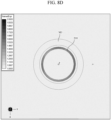
- FIG. 8C and FIG. 8D indicate an example of after magnetization has been performed by a magnetization device 300 illustrated in FIG. 10A and FIG. 10B as a comparative example.
- FIG. 8C indicates a distribution of a magnetic-flux density of the object 200 in the axial direction on a cross-sectional surface of a planar surface including the axis of the object 200 (corresponding to FIG. 8A )
- FIG. 8D indicates a distribution of the magnetic-flux density of the object 200 in a direction perpendicular to the axis on a cross-sectional surface of a planar surface perpendicular to the axis of the object 200 (corresponding to FIG. 8B ).
- the magnetization device 100 according to Embodiment 1 has the same degree of magnetization capability as that of the magnetization device 300 according to the comparative example.
- FIG. 8E and FIG. 8F indicate an example of after magnetization has been performed by the magnetization device according to a first modified example of Embodiment 1.
- the ring-shaped portion 20 has a single layer (that is, the outer ring-shaped portion 20a is omitted).
- FIG. 8E indicates a distribution of a magnetic-flux density of the object 200 in the axial direction on a cross-sectional surface of a planar surface including the axis of the object 200
- FIG. 8F indicates a distribution of the magnetic-flux density of the object 200 in the direction perpendicular to the axis on a cross-sectional surface of a planar surface perpendicular to the axis of the object 200.
- FIG. 8A By comparing FIG. 8A with FIG. 8E , and comparing FIG. 8B with FIG. 8F , it can be seen that the layers of the ring-shaped portion 20 has decreased, and therefore, by the number of the magnets M having decreased, the magnetization capability has weakened. Thus, the magnetization capability is easily adjustable according to the required magnetization amount.
- FIG. 8G and FIG. 8H indicate an example of after magnetization has been performed by a magnetization device of a second modified example according to Embodiment 1.
- the ring-shaped portion 20 has three layers (that is, an additional layer is arranged further outside of the outer ring-shaped portion 20a).
- FIG. 8G indicates a distribution of a magnetic-flux density of the object 200 in the axial direction on a cross-sectional surface of a planar surface including the axis of the object 200
- FIG. 8H indicates a distribution of the magnetic-flux density of the object 200 in the direction perpendicular to the axis on a cross-sectional surface of a planar surface perpendicular to the axis of the object 200.
- FIG. 8A By comparing FIG. 8A with FIG. 8G , and compare FIG. 8B with FIG. 8H , it can be seen that the layers of the ring-shaped portion 20 have increased, and therefore, by the number of the magnets M having increased, the magnetization capability has strengthened. Thus, the magnetization capability is easily adjustable according to the required magnetization amount.
- the unit component 11 by attaching a smoothing member to a portion (a surface opposed to the object 200, for example) in contact with the object 200, the contact with the object 200 can be further smoothened.
- the smoothing member can be constituted of resin, for example, and can be fixed to the unit component 11 using adhesive tape.
- the coupling component 30 is not limited to the one using a screw such as the coupling screw 31, and any lock mechanism may be used.
- a use of a buckle and a hinge is possible.
- the structure for coupling the unit component 11 is not limited to the one using the hinge 14. As long as the adjacent unit components 11 can turn or move with respect to one another, any known coupling structure can be used.
- the fixing method of the magnets M to the unit component 11 is appropriately changeable.
- the fixing of the pedestal 12 and the fixed component 13 may be realized without a screw such as the fixation screw 15.
- the pedestal 12 and the fixed component 13 can be constituted of a single component or three or more components.
- the respective unit components 11 are configured such that they are each able to hold the maximum of one magnet M. However, as a modified example, it may be configured such that the unit components 11 can each hold a plurality of the magnets M.
- a handle may be attached to the magnet holding device 10 or the magnetization device 100. Thus, conveyance and operation become easier.
- the handle can have a configuration similar to that of the handle 350 illustrated in FIG. 10A and FIG. 10B , for example.
Landscapes
- Engineering & Computer Science (AREA)
- Power Engineering (AREA)
- Physics & Mathematics (AREA)
- Electromagnetism (AREA)
- Measuring Magnetic Variables (AREA)
Abstract
Description
- The present invention relates to a magnet holding device, a magnetization device, and a magnetizing method.
- A measurement by magnetism can be employed for detecting wall thinning of a pipe caused by corrosion or the like. First, the pipe is magnetized, and its magnetic-flux density before the wall thinning is measured in advance. Afterwards, upon inspection, the magnetic-flux density around the pipe is measured again, and the wall thinning of the pipe can be detected based on a change in the magnetic-flux density.
-
FIG. 9 illustrates an exemplary configuration of a magnet M1 used in the measuring method. The magnet M1 is constituted of two half-doughnut shaped components. -
FIG. 10A and FIG. 10B illustrate exemplary configurations of amagnetization device 300 including the magnet M1. The magnet M1 is fixed by anouter shell component 310 and aresin member 320. Theouter shell component 310 is openable/closable by abuckle 330 and ahinge 340.FIG. 10A illustrates a state where thebuckle 330 is open, andFIG. 10B illustrates a state where thebuckle 330 is engaged. Themagnetization device 300 can be opened/closed and moved by gripping ahandle 350. - Since the magnet M1 is used in a size according to a size of the pipe, the magnet M1 having various sizes is required.
JP 2019-114696 A - However, in the conventional technique, there has been a problem that a magnetization device appropriate for various magnetization requirements is difficult to be provided.
- For example, according to a diameter or a required magnetization capability of a pipe, magnets having various configurations are required to be prepared. However, in the method of
JP 2019-114696 A - The present invention provides a magnetization device appropriate for various magnetization requirements. In addition, the present invention provides a magnet holding device and a magnetizing method related to the magnetization device.
- One example of a magnet holding device according to the present invention is
a magnet holding device capable of holding a magnet, comprising: - a ring-shaped portion that is openable/closable; and
- an open/close mechanism allowed to keep the ring-shaped portion in a closed state,
- wherein at least one magnet is arrangeable in the ring-shaped portion, and a number of the magnets to be arranged is variable.
- In one example, the magnet has a columnar shape, and a plurality of the magnets are arrangeable along a circumferential direction of the ring-shaped portion.
- In one example,
- the ring-shaped portion includes a plurality of unit components,
- each of the unit components is capable of holding the magnet, and
- each of the unit components is rotatably coupled to another adjacent unit component of the plurality of unit components.
- In one example, a number of the unit components included in the ring-shaped portion is variable to change a size of the ring-shaped portion.
- In one example, a magnetization amount by the magnets is changeable by changing a number of the magnets.
- In one example, the open/close mechanism includes a coupling component disposed in both ends in the circumferential direction of the ring-shaped portion.
- One example of a magnetization device according to the present invention comprises the above-described magnet holding device and a magnet to be arranged in the magnet holding device.
- One example of a magnetizing method according to the present invention is a magnetizing method of magnetizing an object using the above-described magnetization device, comprising:
- arranging the object in the ring-shaped portion in a state where the ring-shaped portion is open;
- attaching the magnetization device to the object by closing the ring-shaped portion using the open/close mechanism after the arranging;
- relatively moving the magnetization device with respect to the object in a state where the magnetization device is attached to the object;
- opening the ring-shaped portion using the open/close mechanism after the moving; and
- detaching the magnetization device from the object after the opening.
- With the magnet holding device, the magnetization device, and the magnetizing method according to the present invention, a magnetization device appropriate for various magnetization requirements can be more easily provided.
-
-
FIG. 1 is an exemplary configuration of a magnetization device according toEmbodiment 1 of the present invention; -
FIG. 2 is a drawing of the magnetization device inFIG. 1 viewed from a different angle; -
FIG. 3A to FIG. 3D are exemplary configurations of a unit component inFIG. 1 ; -
FIG. 4 is a drawing describing a coupling of adjacent unit components; -
FIG. 5A to FIG. 5D are exemplary configurations of coupling components inFIG. 1 ; -
FIG. 6 is a flowchart describing a magnetizing method according toEmbodiment 1; -
FIG. 7 is a drawing of a halfway state in the magnetizing method inFIG. 6 ; -
FIG. 8A is a distribution of a magnetic-flux density of the object in an axial direction after magnetizing has been performed by the magnetization device inFIG. 1 (a cross-sectional surface of a planar surface including the axis); -
FIG. 8B is a distribution of the magnetic-flux density of the object in a direction perpendicular to the axis after magnetizing has been performed by the magnetization device inFIG. 1 (a cross-sectional surface of a planar surface perpendicular to the axis); -
FIG. 8C is a distribution of a magnetic-flux density of the object in the axial direction after magnetizing has been performed by a magnetization device inFIG. 10A and FIG. 10B as a comparative example (a cross-sectional surface of a planar surface including the axis; -
FIG. 8D is a distribution of the magnetic-flux density of the object in the direction perpendicular to the axis after magnetizing has been performed by the magnetization device inFIG. 10A and FIG. 10B as the comparative example (a cross-sectional surface of a planar surface perpendicular to the axis); -
FIG. 8E is a distribution of a magnetic-flux density of the object in the axial direction after magnetizing has been performed by a magnetization device according to a first modified example of Embodiment 1 (a cross-sectional surface of a planar surface including the axis); -
FIG. 8F is a distribution of the magnetic-flux density of the object in the direction perpendicular to the axis after magnetizing has been performed by the magnetization device according to the first modified example of Embodiment 1 (a cross-sectional surface of a planar surface perpendicular to the axis); -
FIG. 8G is a distribution of a magnetic-flux density of the object in the axial direction after magnetizing has been performed on a magnetization device according to a second modified example of Embodiment 1 (a cross-sectional surface of a planar surface including the axis); -
FIG. 8H is a distribution of the magnetic-flux density of the object in a direction perpendicular to the axis after magnetizing has been performed on the magnetization device according to the second modified example of Embodiment 1 (a cross-sectional surface of a planar surface perpendicular to the axis); -
FIG. 9 is an exemplary configuration of a magnet used in a conventional measuring method; and -
FIG. 10A and FIG. 10B are exemplary configurations of a magnetization device including the magnet inFIG. 9 . - The following describes an embodiment of the present invention based on the attached drawings.
-
FIG. 1 illustrates an exemplary configuration of amagnetization device 100 according toEmbodiment 1 of the present invention.FIG. 2 is a drawing of themagnetization device 100 viewed from an angle different from that ofFIG. 1 . - The
magnetization device 100 includes amagnet holding device 10 and a plurality of magnets M. Themagnet holding device 10 is capable of holding the plurality of magnets M, and the magnets M are arranged in themagnet holding device 10. The magnet M is a permanent magnet as an example, and may also be what is called a general-purpose magnet. While the magnet M has a columnar shape in the present embodiment, it may also have another shape. - The
magnet holding device 10 includes a ring-shapedportion 20 that is openable/closable. In the present embodiment, the ring-shapedportion 20 is constituted of two layers, and includes an outer ring-shapedportion 20a and an inner ring-shapedportion 20b. The ring-shapedportion 20 includes a plurality ofunit components 11, and is configured by therespective unit components 11 being coupled in a ring shape. Theunit components 11 can each hold the magnet M. Thus, the magnet M is arrangeable in the ring-shapedportion 20, and particularly, a plurality of the magnets M are arrangeable along a circumferential direction of the ring-shapedportion 20. - Note that, in the present specification, a "circumferential direction," a "radial direction," and an "axial direction" respectively corresponds to a circumferential direction, a radial direction, and an axial direction of a circular ring when the ring-shaped
portion 20 is coupled so as to form the circular ring. However, even when the ring-shapedportion 20 does not form a true circle, these directions are appropriately definable. For example, when the ring-shapedportion 20 is arranged so as to form a ring on a planar surface, a direction perpendicular to the planar surface can be assumed to be the axial direction, and the radial direction and the circumferential direction can be defined with a predetermined position (a point inside the ring-shapedportion 20, for example) on the planar surface as reference. - The
magnet holding device 10 includes an open/close mechanism. The open/close mechanism includes coupling components 30 (more precisely, in the present embodiment, at least one of thecoupling components 30 works as the open/close mechanism). Thecoupling component 30 is disposed on both ends in the circumferential direction of the ring-shapedportion 20, and is configured to be able to keep the ring-shapedportion 20 in a closed state. - In the examples of
FIG. 1 andFIG. 2 , both ends in the circumferential direction of the outer ring-shapedportion 20a are coupled and fixed by acoupling component 30a, and thereby the outer ring-shapedportion 20a is closed. Similarly, both ends in the circumferential direction of the inner ring-shapedportion 20b are coupled and fixed by acoupling component 30b, and thereby the inner ring-shapedportion 20b is closed. - The
coupling component 30 may have functions besides as the open/close mechanism. In the present embodiment, acoupling component 30c couples and fixes the outer ring-shapedportion 20a and the inner ring-shapedportion 20b with one another. Moreover, while thecoupling component 30a and thecoupling component 30b as the open/close mechanism, and thecoupling component 30c for coupling the plurality of ring-shaped portions with one another are coupling components having the same structure in the present embodiment, thecoupling component 30a, thecoupling component 30b, and thecoupling component 30c may be coupling components having different structures. That is, the coupling in the circumferential direction and the coupling in the radial direction of the ring-shaped portion can be implemented by coupling components having different structures. -
FIG. 3A to FIG. 3D illustrate exemplary configurations of theunit component 11.FIG. 3A is a perspective view,FIG. 3B is a drawing (top view) ofFIG. 3A viewed in the IIIB-direction,FIG. 3C is a drawing (front view) ofFIG. 3A viewed in the IIIC-direction, andFIG. 3D is a drawing (side view) ofFIG. 3A viewed in the IIID-direction. - The
unit component 11 includes apedestal 12, a fixedcomponent 13, ahinge 14, and afixation screw 15. Thepedestal 12, the fixedcomponent 13, thehinge 14, and thefixation screw 15 are constituted of a non-magnetic body, for example, and as a specific example, they are constituted of stainless steel. Thefixation screw 15 fixes thepedestal 12 and the fixedcomponent 13, and thereby the magnet M is fixed between thepedestal 12 and the fixedcomponent 13. - Note that, when using the magnet M having a column shape, a magnetization direction of the magnet M can be an axial direction of the column. However, it is preferable for the magnetization direction of the magnet M to coincide with the axial direction of the ring-shaped
portion 20. - A coupling of
adjacent unit components 11 will be described usingFIG. 4 . Theunit component 11 is rotatably coupled to anotheradjacent unit component 11 by thehinge 14. For example, connectingholes 14a as illustrated inFIG. 3A and FIG. 3B are formed in thehinge 14, and coupling screws 16 are inserted through these connectingholes 14a. In addition, connectingholes 12a illustrated inFIG. 3A are formed in thepedestal 12. - As illustrated in
FIG. 4 , the coupling screws 16 are screwed with the connectingholes 12a of an adjacentsecond unit component 11 via the connectingholes 14a of afirst unit component 11. Thus, twounit components 11 are fastened and coupled. Similarly,more unit components 11 are successively coupled, and the ring-shapedportion 20 can be constituted of any number of theunit components 11. - The coupling of the
adjacent unit components 11 can be released by detaching the coupling screws 16. Thus, since therespective unit components 11 are detachably coupled, the number of theunit components 11 included in the ring-shapedportion 20 is variable, and thereby the size (diameter, for example) of the ring-shapedportion 20 is changeable. - In the example of
FIG. 3A, to FIG. 3D , two of each of the connectinghole 14a and the connectinghole 12a are presented. However, four of each of the connectinghole 14a and the connectinghole 12a including those that are in positions not presented inFIG. 3A to FIG. 3D are disposed. That is, while the connectingholes 14a and the connecting holes12a in positions where thehinge 14 and thepedestal 12 overlap are hidden and cannot be seen inFIG. 3A to FIG. 3D , as illustrated inFIG. 3C , the coupling screws 16 are used to fasten and fix thehinge 14 and thepedestal 12. -
FIG. 5A to FIG. 5D illustrate exemplary configurations of thecoupling component 30.FIG. 5A is a perspective view,FIG. 5B is a drawing (top view) ofFIG. 5A viewed in a VB direction,FIG. 5C is a drawing (front view) ofFIG. 5A viewed in a VC-direction, andFIG. 5D is a drawing (side view) ofFIG. 5A viewed in a VD-direction. - The
coupling component 30 includes twocoupling screws 31, two supportingmembers 32, and two opening/closing screws 33. Theentire coupling component 30 is constituted of a non-magnetic body, for example, and as a specific example, it is constituted of stainless steel. - The respective opening/closing screws 33 are screwed with the supporting
members 32, and relatively fix these supportingmembers 32. In addition, acoupling screw 31 is insertable through the supportingmember 32. As illustrated inFIG. 3A to FIG. 3D andFIG. 4 , a connectinghole 13a is formed in the fixedcomponent 13 of theunit component 11, and thecoupling screw 31 can be screwed with the connectinghole 13a. Two coupling screws 31 are each fastened to adifferent unit component 11, and thereby thoseunit components 11 are coupled to one another. Note that, the supporting member 32 (supportingmember 32a) that is closer to the heads of the opening/closing screws 33 of the two supportingmembers 32 may include through holes (what is called clearance holes) for the opening/closing screws 33 to be inserted through instead of screw holes that are screwed with the opening/closing screws 33. - A magnetizing method for magnetizing an object using the
magnetization device 100 will be described usingFIG. 6 and FIG. 7. FIG. 6 is a flowchart describing the magnetizing method according to the present embodiment.FIG. 7 is a drawing of a halfway state in the magnetizing method inFIG. 6 . As illustrated inFIG. 7 , it is preferable to preliminarily leave a marking 201 indicating a range that is to be magnetized on anobject 200 such as a pipe. - The magnetizing method according to the present embodiment includes each step indicated in
FIG. 6 . First, a user of themagnetization device 100 arranges theobject 200 in the ring-shapedportion 20 in a state where the ring-shapedportion 20 is open (Step S1, arranging step). Theobject 200 is a pipe, for example, and is the target of a magnetization effect of themagnetization device 100. - After Step S1, the user attaches the
magnetization device 100 to theobject 200 by closing the ring-shapedportion 20 using the coupling component 30 (Step S2, attaching step). For example, the twocoupling screws 31 of thecoupling component 30 are each fastened to acorresponding unit component 11, and these coupling screws 31 are fixed by the two opening/closing screws 33. Note that, an attachment position of themagnetization device 100 can be one end of the marking 201. - After Step S2, the
magnetization device 100 is relatively moved by being slid with respect to theobject 200 in a state where themagnetization device 100 is attached to the object 200 (Step S3, moving step). A direction of the movement is, for example, an axial direction of the ring-shapedportion 20 or an axial direction of the object 200 (these directions coincide in the present embodiment). This movement is performed up to another end of the marking 201.FIG. 7 presents a halfway state in this step S3. In Step S1 and Step S3, by the magnets M being arranged with respect to theobject 200 and passing through its periphery, theobject 200 becomes magnetized. - Thus, by moving the
magnetization device 100 in a predetermined axial direction range along theobject 200, theobject 200 can be magnetized in the axial direction range. Moreover, by attaching the ring-shaped portion holding the plurality of magnets M such that they are wound along the circumferential direction of theobject 200, an approximately uniform magnetization in the circumferential direction of theobject 200 is possible. - After Step S3, the user opens the ring-shaped
portion 20 by the coupling component 30 (Step S4, opening step). More specifically, the two opening/closing screws 33 or at least one of the coupling screws 31 are detached from thecoupling component 30. - After Step S4, the user detaches the
magnetization device 100 from the object 200 (Step S5, detaching step). Accordingly, the magnetizing method according to the present embodiment is terminated. - In the present embodiment, the magnets M are arrangeable in the ring-shaped
portion 20 as described above, and the number of the magnets M to be arranged is variable and appropriately changeable according to the magnetization requirements. For example, since the number of theunit components 11 included in the ring-shapedportion 20 is variable, when the diameter of theobject 200 is large or small, the number of theunit components 11 can be increased or decreased according to the diameter to constitute themagnetization device 100 having a size fit for theobject 200. - By changing the number of the magnets M with respect to the
object 200 having the same size, the magnetization amount by the magnets M is changeable. For example, when magnetization should be decreased with respect to theobject 200 having the same size, by not arranging the magnets M in a part of themultiple unit components 11, the number of the magnets M can be decreased and the magnetization capability of themagnetization device 100 can be weakened. - When the magnetization should be increased with respect to the
object 200 having the same size, by coupling theunit components 11 not only in the circumferential direction but also the radial direction, the number of the magnets M can be increased and the magnetization capability of themagnetization device 100 as a whole can be strengthened. In the examples ofFIG. 1 andFIG. 2 , two layers of theunit components 11 in the radial direction are arranged. By making this a single layer, the magnetization capability can be weakened, and by making this three layers or more, the magnetization capability can be strengthened. - As described above, with the
magnet holding device 10 and themagnetization device 100 according toEmbodiment 1, a magnetization device appropriate for various magnetization requirements can be more easily provided. - A specific example of an effect of the present invention will be described below using
FIG. 8A to FIG. 8H . These figures indicate distributions of the magnetic-flux density of theobject 200 in the axial direction, and have been obtained as a result of an electromagnetic field analysis using a model. A z-direction in the figures indicates the axial direction of theobject 200, and the x-direction and the y-direction indicate the radial direction of theobject 200. In a cross-sectional surface of theobject 200, the gray becomes dark as the magnetic-flux density increases. -
FIG. 8A andFIG. 8B indicate an example of after magnetization has been performed by themagnetization device 100 according toEmbodiment 1. In particular,FIG. 8A indicates a distribution of the magnetic-flux density of theobject 200 in the axial direction on a cross-sectional surface of a planar surface including the axis of theobject 200, andFIG. 8B indicates a distribution of the magnetic-flux density of theobject 200 in a direction perpendicular to the axis on a cross-sectional surface of a planar surface perpendicular to the axis of theobject 200. -
FIG. 8C andFIG. 8D indicate an example of after magnetization has been performed by amagnetization device 300 illustrated inFIG. 10A and FIG. 10B as a comparative example. In particular,FIG. 8C indicates a distribution of a magnetic-flux density of theobject 200 in the axial direction on a cross-sectional surface of a planar surface including the axis of the object 200 (corresponding toFIG. 8A ), andFIG. 8D indicates a distribution of the magnetic-flux density of theobject 200 in a direction perpendicular to the axis on a cross-sectional surface of a planar surface perpendicular to the axis of the object 200 (corresponding toFIG. 8B ). - By these results, it can be seen that the
magnetization device 100 according toEmbodiment 1 has the same degree of magnetization capability as that of themagnetization device 300 according to the comparative example. -
FIG. 8E andFIG. 8F indicate an example of after magnetization has been performed by the magnetization device according to a first modified example ofEmbodiment 1. In the first modified example, the ring-shapedportion 20 has a single layer (that is, the outer ring-shapedportion 20a is omitted).FIG. 8E indicates a distribution of a magnetic-flux density of theobject 200 in the axial direction on a cross-sectional surface of a planar surface including the axis of theobject 200, andFIG. 8F indicates a distribution of the magnetic-flux density of theobject 200 in the direction perpendicular to the axis on a cross-sectional surface of a planar surface perpendicular to the axis of theobject 200. - By comparing
FIG. 8A withFIG. 8E , and comparingFIG. 8B withFIG. 8F , it can be seen that the layers of the ring-shapedportion 20 has decreased, and therefore, by the number of the magnets M having decreased, the magnetization capability has weakened. Thus, the magnetization capability is easily adjustable according to the required magnetization amount. -
FIG. 8G andFIG. 8H indicate an example of after magnetization has been performed by a magnetization device of a second modified example according toEmbodiment 1. In the second modified example, the ring-shapedportion 20 has three layers (that is, an additional layer is arranged further outside of the outer ring-shapedportion 20a).FIG. 8G indicates a distribution of a magnetic-flux density of theobject 200 in the axial direction on a cross-sectional surface of a planar surface including the axis of theobject 200, andFIG. 8H indicates a distribution of the magnetic-flux density of theobject 200 in the direction perpendicular to the axis on a cross-sectional surface of a planar surface perpendicular to the axis of theobject 200. - By comparing
FIG. 8A withFIG. 8G , and compareFIG. 8B withFIG. 8H , it can be seen that the layers of the ring-shapedportion 20 have increased, and therefore, by the number of the magnets M having increased, the magnetization capability has strengthened. Thus, the magnetization capability is easily adjustable according to the required magnetization amount. - In the above-described
Embodiment 1, modification as the following can be further made. In theunit component 11, by attaching a smoothing member to a portion (a surface opposed to theobject 200, for example) in contact with theobject 200, the contact with theobject 200 can be further smoothened. The smoothing member can be constituted of resin, for example, and can be fixed to theunit component 11 using adhesive tape. - The
coupling component 30 is not limited to the one using a screw such as thecoupling screw 31, and any lock mechanism may be used. For example, a use of a buckle and a hinge is possible. - The structure for coupling the
unit component 11 is not limited to the one using thehinge 14. As long as theadjacent unit components 11 can turn or move with respect to one another, any known coupling structure can be used. - The fixing method of the magnets M to the
unit component 11 is appropriately changeable. For example, the fixing of thepedestal 12 and the fixedcomponent 13 may be realized without a screw such as thefixation screw 15. Alternately, thepedestal 12 and the fixedcomponent 13 can be constituted of a single component or three or more components. - In
Embodiment 1, therespective unit components 11 are configured such that they are each able to hold the maximum of one magnet M. However, as a modified example, it may be configured such that theunit components 11 can each hold a plurality of the magnets M. - A handle may be attached to the
magnet holding device 10 or themagnetization device 100. Thus, conveyance and operation become easier. The handle can have a configuration similar to that of thehandle 350 illustrated inFIG. 10A and FIG. 10B , for example. -
- M
- Magnet
- 10
- Magnet holding device
- 11
- Unit component
- 12
- Pedestal
- 12a
- Connecting hole
- 13
- Fixed component
- 13a
- Connecting hole
- 14
- Hinge
- 14a
- Connecting hole
- 15
- Fixation screw
- 16
- Coupling screw
- 20
- Ring-shaped portion (20a : Outer ring-shaped portion, 20b: Inner ring-shaped portion)
- 30 (30a, 30b, 30c)
- Coupling component
- 31
- Coupling screw
- 32 (32a)
- Supporting member
- 33
- Opening/closing screw
- 100
- Magnetization device
- 200
- Object
- 201
- Marking
Claims (8)
- A magnet holding device capable of holding a magnet, comprising:a ring-shaped portion that is openable/closable; andan open/close mechanism allowed to keep the ring-shaped portion in a closed state,wherein at least one magnet is arrangeable in the ring-shaped portion, and a number of the magnets to be arranged is variable.
- The magnet holding device according to claim 1,
wherein the magnet has a columnar shape, and a plurality of the magnets are arrangeable along a circumferential direction of the ring-shaped portion. - The magnet holding device according to claim 2,wherein the ring-shaped portion includes a plurality of unit components,wherein each of the unit components is capable of holding the magnet, andwherein each of the unit components is rotatably coupled to another adjacent unit component of the plurality of unit components.
- The magnet holding device according to claim 3,
wherein a number of the unit components included in the ring-shaped portion is variable to change a size of the ring-shaped portion. - The magnet holding device according to claim 4,
wherein a magnetization amount by the magnets is changeable by changing a number of the magnets. - The magnet holding device according to claim 1,
wherein the open/close mechanism includes a coupling component disposed in both ends in the circumferential direction of the ring-shaped portion. - A magnetization device comprising:the magnet holding device according to claim 1; andat least one magnet to be arranged in the magnet holding device.
- A magnetizing method of magnetizing an object using the magnetization device according to claim 7, comprising:arranging the object in the ring-shaped portion in a state where the ring-shaped portion is open;attaching the magnetization device to the object by closing the ring-shaped portion using the open/close mechanism after the arranging;relatively moving the magnetization device with respect to the object in a state where the magnetization device is attached to the object;opening the ring-shaped portion using the open/close mechanism after the moving; anddetaching the magnetization device from the object after the opening.
Applications Claiming Priority (1)
| Application Number | Priority Date | Filing Date | Title |
|---|---|---|---|
| JP2022062245A JP7567851B2 (en) | 2022-04-04 | 2022-04-04 | Magnet holding device, magnetization device and magnetization method |
Publications (1)
| Publication Number | Publication Date |
|---|---|
| EP4258299A1 true EP4258299A1 (en) | 2023-10-11 |
Family
ID=85795519
Family Applications (1)
| Application Number | Title | Priority Date | Filing Date |
|---|---|---|---|
| EP23165904.6A Pending EP4258299A1 (en) | 2022-04-04 | 2023-03-31 | Magnet holding device, magnetization device, and magnetizing method |
Country Status (4)
| Country | Link |
|---|---|
| US (1) | US12300430B2 (en) |
| EP (1) | EP4258299A1 (en) |
| JP (1) | JP7567851B2 (en) |
| CN (1) | CN116895426A (en) |
Citations (5)
| Publication number | Priority date | Publication date | Assignee | Title |
|---|---|---|---|---|
| US4941236A (en) * | 1989-07-06 | 1990-07-17 | Timex Corporation | Magnetic clasp for wristwatch strap |
| JP2006020494A (en) * | 2004-05-31 | 2006-01-19 | Kokusan Denki Co Ltd | Magnet-holding spacer for flywheel magnet rotor, and the flywheel magnet rotor |
| US20060038647A1 (en) * | 2004-08-17 | 2006-02-23 | Bret Wooten | Magnetic metal accessory holder |
| JP2019114696A (en) | 2017-12-25 | 2019-07-11 | Tdk株式会社 | Permanent magnet piece, permanent magnet assembly, and permanent magnet application device |
| US20210074459A1 (en) * | 2019-09-09 | 2021-03-11 | Apple Inc. | Magnet alternating pole array magnetized by one side magnetization to boost magnetic attraction force |
Family Cites Families (13)
| Publication number | Priority date | Publication date | Assignee | Title |
|---|---|---|---|---|
| US5319335A (en) * | 1992-07-29 | 1994-06-07 | Industrial Technology Research Institute | Apparatus for magnetizing a magnetic roller |
| JP2556957Y2 (en) * | 1993-04-13 | 1997-12-08 | 東京製綱株式会社 | Wire rope damage detector |
| JP3022100U (en) | 1995-08-29 | 1996-03-12 | 株式会社協永アクセサリー | bracelet |
| JP2000210386A (en) | 1999-01-27 | 2000-08-02 | Hiroshi Sato | Health belt and electromagnetic barrel chain body for this purpose and electromagnetic barrel body |
| US7538650B2 (en) * | 2006-07-17 | 2009-05-26 | Smith International, Inc. | Apparatus and method for magnetizing casing string tubulars |
| JP2009175027A (en) | 2008-01-25 | 2009-08-06 | Jfe Engineering Corp | Magnetizer, In-pipe inspection device |
| CN201366190Y (en) | 2008-12-31 | 2009-12-23 | 施金德 | massage device |
| JP5428012B2 (en) | 2009-11-12 | 2014-02-26 | 株式会社日本衛生センター | Magnet health equipment |
| CN102360696B (en) * | 2011-06-10 | 2013-07-31 | 沈阳隆基电磁科技股份有限公司 | Open and close type monocrystal permanent magnetic field structure |
| DE102011086214A1 (en) | 2011-11-11 | 2013-05-16 | Magnet-Physik Dr. Steingroever Gmbh | Method and device for holding magnet bodies during their magnetization and for introducing the magnetized magnet bodies into a component of a magnetic system |
| KR20190101998A (en) | 2016-12-13 | 2019-09-02 | 도쿄 세이꼬 가부시키가이샤 | Damage detection method of wire rope, and signal processing device and damage detection device used for damage detection of wire rope |
| JP7170068B2 (en) | 2019-01-23 | 2022-11-11 | 株式会社日立製作所 | Permanent magnet device and magnetic field generator |
| JP7147801B2 (en) | 2020-03-13 | 2022-10-05 | 横河電機株式会社 | Magnetic flaw detection method, magnetic field measurement processing device, and magnetic flaw detection device |
-
2022
- 2022-04-04 JP JP2022062245A patent/JP7567851B2/en active Active
-
2023
- 2023-03-28 US US18/127,134 patent/US12300430B2/en active Active
- 2023-03-31 EP EP23165904.6A patent/EP4258299A1/en active Pending
- 2023-04-03 CN CN202310347251.6A patent/CN116895426A/en active Pending
Patent Citations (5)
| Publication number | Priority date | Publication date | Assignee | Title |
|---|---|---|---|---|
| US4941236A (en) * | 1989-07-06 | 1990-07-17 | Timex Corporation | Magnetic clasp for wristwatch strap |
| JP2006020494A (en) * | 2004-05-31 | 2006-01-19 | Kokusan Denki Co Ltd | Magnet-holding spacer for flywheel magnet rotor, and the flywheel magnet rotor |
| US20060038647A1 (en) * | 2004-08-17 | 2006-02-23 | Bret Wooten | Magnetic metal accessory holder |
| JP2019114696A (en) | 2017-12-25 | 2019-07-11 | Tdk株式会社 | Permanent magnet piece, permanent magnet assembly, and permanent magnet application device |
| US20210074459A1 (en) * | 2019-09-09 | 2021-03-11 | Apple Inc. | Magnet alternating pole array magnetized by one side magnetization to boost magnetic attraction force |
Also Published As
| Publication number | Publication date |
|---|---|
| CN116895426A (en) | 2023-10-17 |
| US20230317339A1 (en) | 2023-10-05 |
| US12300430B2 (en) | 2025-05-13 |
| JP7567851B2 (en) | 2024-10-16 |
| JP2023152328A (en) | 2023-10-17 |
Similar Documents
| Publication | Publication Date | Title |
|---|---|---|
| US8148988B2 (en) | Magnet arrangement and method for providing a magnetic field in a sensitive volume | |
| US7501812B2 (en) | Combined sensor and bearing assembly and method of magnetizing element of rotation sensor | |
| CN108603920B (en) | Magnetic field measurement method and magnetic field measurement device | |
| JP2006075372A5 (en) | ||
| US20150369887A1 (en) | Methods and apparatuses related to instrumentation for magnetic relaxometry measurements | |
| US8009000B2 (en) | Apparatus for application of a magnetic field to a sample | |
| US7656158B2 (en) | Sample holder for NMR measurements with field homogenization in the sample volume by means of the bordering surfaces of the sample holder | |
| CN107093508B (en) | Magnet assembly and sensor equipment | |
| US12300430B2 (en) | Magnet holding device, magnetization device, and magnetizing method | |
| Arbenz et al. | Characterization of permanent magnet magnetization | |
| JPS60194339A (en) | Nuclear magnetic resonance apparatus | |
| JP2010148578A (en) | Superconducting quantum interference device (squid) fluxmeter and method for adjusting balance of gradiometer | |
| US11204404B2 (en) | Measurement magnet arrangement | |
| CN107464653A (en) | A magnet structure of a low-field nuclear magnetic resonance probe with a magnetic field switch function | |
| Astrov et al. | External quadrupole magnetic field of antiferromagnetic Cr2O3 | |
| CN114236434B (en) | Saddle-type and Helmholtz coil device applied to atomic magnetometer and use method | |
| US10352886B2 (en) | Probe for detecting structural integrity of part | |
| Ludke et al. | Novel compensated moment detection coil | |
| JP4602910B2 (en) | NMR apparatus and positioning method thereof | |
| Blümler et al. | Halbach Magnets for Magnetic Resonance | |
| JP5026757B2 (en) | NMR probe and NMR apparatus | |
| US10551213B2 (en) | Sickle-shaped magnet arrangement for angle detection | |
| CN109406558B (en) | Single-side nuclear magnetic resonance device | |
| CN216209818U (en) | Support frame structure, magnetic resonance volume coil assembly and magnetic resonance imaging equipment | |
| JP2000182877A (en) | Magnetic circuit for sputtering |
Legal Events
| Date | Code | Title | Description |
|---|---|---|---|
| PUAI | Public reference made under article 153(3) epc to a published international application that has entered the european phase |
Free format text: ORIGINAL CODE: 0009012 |
|
| STAA | Information on the status of an ep patent application or granted ep patent |
Free format text: STATUS: THE APPLICATION HAS BEEN PUBLISHED |
|
| AK | Designated contracting states |
Kind code of ref document: A1 Designated state(s): AL AT BE BG CH CY CZ DE DK EE ES FI FR GB GR HR HU IE IS IT LI LT LU LV MC ME MK MT NL NO PL PT RO RS SE SI SK SM TR |
|
| STAA | Information on the status of an ep patent application or granted ep patent |
Free format text: STATUS: REQUEST FOR EXAMINATION WAS MADE |
|
| 17P | Request for examination filed |
Effective date: 20240207 |
|
| RBV | Designated contracting states (corrected) |
Designated state(s): AL AT BE BG CH CY CZ DE DK EE ES FI FR GB GR HR HU IE IS IT LI LT LU LV MC ME MK MT NL NO PL PT RO RS SE SI SK SM TR |