EP4258080A1 - Control apparatus and method for laser apparatus, and laser measuring apparatus - Google Patents
Control apparatus and method for laser apparatus, and laser measuring apparatus Download PDFInfo
- Publication number
- EP4258080A1 EP4258080A1 EP21908536.2A EP21908536A EP4258080A1 EP 4258080 A1 EP4258080 A1 EP 4258080A1 EP 21908536 A EP21908536 A EP 21908536A EP 4258080 A1 EP4258080 A1 EP 4258080A1
- Authority
- EP
- European Patent Office
- Prior art keywords
- temperature
- laser
- laser component
- signal
- voltage
- Prior art date
- Legal status (The legal status is an assumption and is not a legal conclusion. Google has not performed a legal analysis and makes no representation as to the accuracy of the status listed.)
- Withdrawn
Links
Images


Classifications
-
- H—ELECTRICITY
- H01—ELECTRIC ELEMENTS
- H01S—DEVICES USING THE PROCESS OF LIGHT AMPLIFICATION BY STIMULATED EMISSION OF RADIATION [LASER] TO AMPLIFY OR GENERATE LIGHT; DEVICES USING STIMULATED EMISSION OF ELECTROMAGNETIC RADIATION IN WAVE RANGES OTHER THAN OPTICAL
- H01S5/00—Semiconductor lasers
- H01S5/06—Arrangements for controlling the laser output parameters, e.g. by operating on the active medium
- H01S5/068—Stabilisation of laser output parameters
- H01S5/06804—Stabilisation of laser output parameters by monitoring an external parameter, e.g. temperature
-
- G—PHYSICS
- G05—CONTROLLING; REGULATING
- G05D—SYSTEMS FOR CONTROLLING OR REGULATING NON-ELECTRIC VARIABLES
- G05D23/00—Control of temperature
- G05D23/19—Control of temperature characterised by the use of electric means
- G05D23/20—Control of temperature characterised by the use of electric means with sensing elements having variation of electric or magnetic properties with change of temperature
- G05D23/24—Control of temperature characterised by the use of electric means with sensing elements having variation of electric or magnetic properties with change of temperature the sensing element having a resistance varying with temperature, e.g. a thermistor
-
- H—ELECTRICITY
- H01—ELECTRIC ELEMENTS
- H01S—DEVICES USING THE PROCESS OF LIGHT AMPLIFICATION BY STIMULATED EMISSION OF RADIATION [LASER] TO AMPLIFY OR GENERATE LIGHT; DEVICES USING STIMULATED EMISSION OF ELECTROMAGNETIC RADIATION IN WAVE RANGES OTHER THAN OPTICAL
- H01S5/00—Semiconductor lasers
- H01S5/06—Arrangements for controlling the laser output parameters, e.g. by operating on the active medium
- H01S5/068—Stabilisation of laser output parameters
- H01S5/06808—Stabilisation of laser output parameters by monitoring the electrical laser parameters, e.g. voltage or current
-
- H—ELECTRICITY
- H01—ELECTRIC ELEMENTS
- H01S—DEVICES USING THE PROCESS OF LIGHT AMPLIFICATION BY STIMULATED EMISSION OF RADIATION [LASER] TO AMPLIFY OR GENERATE LIGHT; DEVICES USING STIMULATED EMISSION OF ELECTROMAGNETIC RADIATION IN WAVE RANGES OTHER THAN OPTICAL
- H01S5/00—Semiconductor lasers
- H01S5/06—Arrangements for controlling the laser output parameters, e.g. by operating on the active medium
- H01S5/068—Stabilisation of laser output parameters
- H01S5/0683—Stabilisation of laser output parameters by monitoring the optical output parameters
- H01S5/06835—Stabilising during pulse modulation or generation
-
- H—ELECTRICITY
- H03—ELECTRONIC CIRCUITRY
- H03K—PULSE TECHNIQUE
- H03K19/00—Logic circuits, i.e. having at least two inputs acting on one output; Inverting circuits
- H03K19/20—Logic circuits, i.e. having at least two inputs acting on one output; Inverting circuits characterised by logic function, e.g. AND, OR, NOR, NOT circuits
- H03K19/21—EXCLUSIVE-OR circuits, i.e. giving output if input signal exists at only one input; COINCIDENCE circuits, i.e. giving output only if all input signals are identical
-
- H—ELECTRICITY
- H03—ELECTRONIC CIRCUITRY
- H03K—PULSE TECHNIQUE
- H03K7/00—Modulating pulses with a continuously-variable modulating signal
- H03K7/08—Duration or width modulation ; Duty cycle modulation
-
- G—PHYSICS
- G01—MEASURING; TESTING
- G01C—MEASURING DISTANCES, LEVELS OR BEARINGS; SURVEYING; NAVIGATION; GYROSCOPIC INSTRUMENTS; PHOTOGRAMMETRY OR VIDEOGRAMMETRY
- G01C15/00—Surveying instruments or accessories not provided for in groups G01C1/00 - G01C13/00
- G01C15/002—Active optical surveying means
- G01C15/004—Reference lines, planes or sectors
-
- H—ELECTRICITY
- H01—ELECTRIC ELEMENTS
- H01S—DEVICES USING THE PROCESS OF LIGHT AMPLIFICATION BY STIMULATED EMISSION OF RADIATION [LASER] TO AMPLIFY OR GENERATE LIGHT; DEVICES USING STIMULATED EMISSION OF ELECTROMAGNETIC RADIATION IN WAVE RANGES OTHER THAN OPTICAL
- H01S5/00—Semiconductor lasers
- H01S5/04—Processes or apparatus for excitation, e.g. pumping, e.g. by electron beams
- H01S5/042—Electrical excitation ; Circuits therefor
-
- H—ELECTRICITY
- H01—ELECTRIC ELEMENTS
- H01S—DEVICES USING THE PROCESS OF LIGHT AMPLIFICATION BY STIMULATED EMISSION OF RADIATION [LASER] TO AMPLIFY OR GENERATE LIGHT; DEVICES USING STIMULATED EMISSION OF ELECTROMAGNETIC RADIATION IN WAVE RANGES OTHER THAN OPTICAL
- H01S5/00—Semiconductor lasers
- H01S5/06—Arrangements for controlling the laser output parameters, e.g. by operating on the active medium
- H01S5/068—Stabilisation of laser output parameters
- H01S5/06825—Protecting the laser, e.g. during switch-on/off, detection of malfunctioning or degradation
Definitions
- the present disclosure relates to the field of laser measurement and, more particularly, to a control device for a laser component, a control method for the laser component, and a laser measurement device including the above control device.
- the laser component used by the laser measurement tool to generate laser inevitably generates heat during operation, which leads to continuous increase of the temperature of the laser component and the surrounding components.
- the aging degree of the laser component and other surrounding devices thereof may be accelerated and the service life thereof may be reduced.
- the measurement accuracy of such laser measurement tools may also be recurred due to factors such as temperature drift.
- the present disclosure provides a control device and a corresponding control method for controlling the temperature of the laser component by using a logic circuit to change the driving power of the driving signal.
- the first aspect of the present disclosure provides a control device for controlling the temperature of a laser component, where the control device includes: a pulse width modulation (PWM) signal generator, where the PWM signal generator is configured to generate a PWM signal; a temperature acquisition circuit, where the temperature acquisition circuit is configured to acquire a temperature of the laser component and convert the temperature into a measurement voltage; a voltage comparator, where the voltage comparator is configured to compare the measurement voltage associated with the temperature of the laser component with a temperature threshold voltage and output a comparison result signal; and a logic circuit, where the logic circuit is configured to generate a drive signal based on the PWM signal and the comparison result signal to drive the laser component.
- PWM pulse width modulation
- the control device can realize, by using simple components such as a voltage comparator and a logic circuit, temperature comparison and generate a driving signal for driving the laser component according to the PWM signal and the comparison result signal when the temperature exceeds a predetermined threshold.
- the power of the signal driving the laser component can be reduced.
- the temperature of the laser component can be controlled, leading to a longer lifetime and improved accuracy of the laser component at a lower cost and higher reliability.
- a duty ratio of the PWM signal is not less than 5:5.
- the duty ratio of the PWM signal is not less than 7:3.
- the logic circuit includes an Exclusive-OR (XOR) gate circuit.
- the XOR gate circuit is configured to invert, when the acquired measurement voltage associated with the temperature of the laser component is higher than the temperature threshold voltage, the PWM signal to reduce the power to drive the laser component.
- the temperature acquisition circuit includes a temperature sensor.
- the temperature sensor is configured to acquire and convert the temperature of the laser component into a measurement voltage.
- the laser component includes at least one laser diode.
- a second aspect of the present disclosure provides a laser measurement device, where the laser measurement device includes: a laser component, where the laser component is configured to emit laser for measurement; and a control device for controlling the temperature of the laser component according to the first aspect of the present disclosure.
- the laser component includes at least one laser diode.
- the laser measurement device includes a laser leveling device, a laser line projection device and/or a laser distance meter.
- a third aspect of the present disclosure provides a control method for controlling the temperature of a laser component, where the control method includes: generating a PWM signal; acquiring and converting a temperature of the laser component into a measurement voltage; comparing, by a voltage comparator, the acquired measurement voltage associated with the temperature of the laser component with a temperature threshold voltage, and outputting a comparison result signal; and generating, by a logic circuit, a drive signal based on the PWM signal and the comparison result signal to drive the laser component.
- the control device can realize, by using simple components such as a voltage comparator and a logic circuit, temperature comparison and generate a driving signal for driving the laser component according to the PWM signal and the comparison result signal when the temperature exceeds a predetermined threshold.
- the power of the signal driving the laser component can be reduced.
- the temperature of the laser component can be controlled, leading to a longer lifetime and improved accuracy of the laser component at a lower cost and higher reliability.
- a duty ratio of the PWM signal is not less than 5:5.
- the duty ratio of the PWM signal is not less than 7:3.
- the logic circuit includes an XOR gate circuit. More preferably, in an embodiment according to the present disclosure, the control method further includes inverting, by the XOR gate circuit when the acquired measurement voltage associated with the temperature of the laser component is higher than the temperature threshold voltage, the PWM signal to reduce the power to drive the laser component.
- the temperature acquisition circuit includes a temperature sensor, where acquiring the temperature of the laser component further includes acquiring the temperature of the laser component by the temperature sensor.
- the control device can realize, by using simple components such as a voltage comparator and a logic circuit, temperature comparison and generate a driving signal for driving the laser component according to the PWM signal and the comparison result signal when the temperature exceeds a predetermined threshold.
- the power of the signal driving the laser component can be reduced.
- the temperature of the laser component can be controlled, leading to a longer lifetime and improved accuracy of the laser component at a lower cost and higher reliability.
- FIG. 1 shows a schematic structural diagram of a control device 100 for controlling the temperature of the laser component according to an embodiment of the present disclosure.
- the control device 100 for controlling the temperature of the laser component provided according to the present disclosure includes the following parts:
- the control device can realize, by using simple components such as a voltage comparator 140 and a logic circuit 150, temperature comparison and generate a driving signal for driving the laser component according to the PWM signal (generated by the PWM signal generator 110) and the comparison result signal (the comparison result signal output by the voltage comparator 140) when the temperature exceeds a predetermined threshold.
- the power of the signal driving the laser component can be reduced.
- the temperature of the laser component can be controlled, leading to a longer lifetime and improved accuracy of the laser component at a lower cost and higher reliability.
- the temperature acquisition circuit 120 can be implemented as a temperature sensor.
- the present embodiment adopts a thermistor, and the resistance of the thermistor is about 2.3K at 68 degrees.
- This embodiment employs a non-inverting voltage hysteresis comparator as the voltage comparator.
- the technical solution disclosed in the present disclosure uses a hysteresis voltage of about 300mv, a threshold Vh of 1.783v, and a threshold Vl of 1.476v.
- the temperature detection circuit When the temperature rises to 68 degrees, through voltage conversion, the temperature detection circuit generates a voltage greater than 1.783V, and the voltage comparator 140 outputs a high level, which is XORed with the PWM signal generated by the PWM generator 110, thereby reducing the working power of the laser component.
- the PWM generator 110 can use a single-chip microcomputer or a PWM generating circuit to generate a PWM square wave signal.
- the temperature acquisition circuit 120 can use an NTC resistor or a temperature detection chip to acquire the current temperature of the laser component.
- the voltage comparator 150 may use a single-limit comparator, a hysteresis comparator, and/or a window comparator to output the comparison result.
- the logic circuit 150 may use various gate circuits such as an Exclusive-OR gate circuit.
- the voltage comparator 140 compares the set voltage value with the voltage value sampled by the NTC, and performs XOR with the signal of the PWM generator 110, thereby reducing the operating power of the laser component.
- a duty ratio of the PWM signal generated by the PWM signal generator 110 is not less than 5:5.
- the duty ratio of the PWM signal generated by the PWM signal generator 110 is not less than 7:3.
- the logic circuit 150 includes an XOR gate circuit.
- the XOR gate circuit is configured to invert, when the acquired measurement voltage associated with the temperature of the laser component is higher than the temperature threshold voltage, the PWM signal (generated by the PWM signal generator 110) to reduce the power to drive the laser component.
- the temperature acquisition circuit 120 includes a temperature sensor, where the temperature sensor is configured to acquire and convert the temperature of the laser component into a measurement voltage.
- the laser component includes at least one laser diode.
- FIG. 2 shows a schematic structural diagram of a control device 200 for controlling the temperature of the laser component according to an embodiment of the present disclosure.
- the control device 200 for controlling the temperature of the laser component proposed according to the present disclosure includes the following parts:
- the control device can realize, by using simple components such as a voltage comparison circuit 240 and a XOR logic circuit 250, temperature comparison and generate a driving signal for driving the laser component 260 according to the PWM signal (generated by the PWM signal generator 210) and the comparison result signal (the comparison result signal output by the voltage comparator 240) when the temperature exceeds a predetermined threshold.
- the power of the signal driving the laser component 260 can be reduced.
- the temperature of the laser component 260 can be controlled, the working stability of the laser component 260 can be improved, leading to a longer lifetime and improved accuracy of the laser component 260 at a lower cost and higher reliability.
- the temperature sensor 220 can adopt, e.g., a thermistor, and the resistance of the thermistor is about 2.3K at 68 degrees.
- a non-inverting voltage hysteresis comparator is applied.
- the technical solution disclosed in the present disclosure uses a hysteresis voltage of about 300mv, a threshold Vh of 1.783v, and a threshold Vl of 1.476v.
- the temperature detection circuit When the temperature rises to 68 degrees, the temperature detection circuit generates a voltage greater than 1.783V, and the voltage comparison circuit 240 outputs a high level, which is XORed with the PWM signal generated by the PWM generator 210, thereby reducing the working power of the laser component.
- the PWM generator 210 may include a single-chip microcomputer or a PWM generating circuit to generate a PWM square wave signal, and the temperature acquisition circuit 220 can use an NTC resistor or a temperature detection chip to acquire the current temperature of the laser component.
- the voltage comparison circuit 240 may use a single-limit comparator, a hysteresis comparator, and/or a window comparator to output the comparison result.
- the XOR logic circuit 250 may use various gate circuits such as an XOR or other logic gate. The voltage comparison circuit 240 compares the set voltage value with the voltage value sampled by the NTC, and performs XOR with the signal of the PWM generator 210, thereby reducing the operating power of the laser component.
- the duty ratio of the PWM signal generated by the PWM signal generator 210 is not less than 5:5.
- the duty ratio of the PWM signal generated by the PWM signal generator 210 is not less than 7:3.
- the XOR circuit 250 is configured to invert, when the acquired measurement voltage associated with the temperature of the laser component 260 is higher than the temperature threshold voltage, the PWM signal (generated by the PWM signal generator 210) to reduce the power for driving the laser component 260.
- the temperature sensor 220 is configured to acquire the temperature of the laser component 260 and convert it into the measurement voltage.
- the laser component 260 includes at least one laser diode.
- FIG. 3 shows a schematic structural diagram of a laser measurement device 300 including the control device shown in FIG. 1 or FIG. 2 .
- the laser measurement device 300 provided by the second aspect of the present disclosure includes a laser component 360, where the laser component 360 is configured to emit laser for measurement.
- the laser measurement device 300 provided in the second aspect further includes the control device 100 proposed according to the first aspect of the present disclosure for controlling the temperature of the laser component.
- the laser component 360 includes at least one laser diode.
- the laser measurement device 300 may be any one of a laser leveling device, a laser line projection device, a laser spot projection device, and a laser distance meter. That is, the control device 100 for controlling the temperature of a laser component proposed according to the present disclosure can be applied to any measuring device having a laser component, and it can control the temperature of the laser component, thereby improving the service life of the laser component.
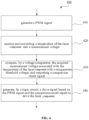
- FIG. 4 shows a schematic flowchart of a control method 400 for controlling the temperature of the laser component according to an embodiment of the present disclosure.
- the control method 400 for controlling the temperature of a laser component provided by the third aspect of the present disclosure includes the following method steps:
- a duty ratio of the PWM signal is not less than 5:5.
- the duty ratio of the PWM signal is not less than 7:3.
- the logic circuit includes an XOR gate circuit. More preferably, in an embodiment according to the present disclosure, the control method further includes inverting, by the XOR gate circuit when the acquired measurement voltage associated with the temperature of the laser component is higher than the temperature threshold voltage, the PWM signal to reduce the power to drive the laser component.
- the temperature acquisition circuit includes a temperature sensor, where acquiring the temperature of the laser component further includes acquiring the temperature of the laser component by the temperature sensor.
- the control device can realize, by using simple components such as a voltage comparator and a logic circuit, temperature comparison and generate a driving signal for driving the laser component according to the PWM signal and the comparison result signal when the temperature exceeds a predetermined threshold.
- the power of the signal driving the laser component can be reduced.
- the temperature of the laser component can be controlled, leading to a longer lifetime and improved accuracy of the laser component at a lower cost and higher reliability.
Landscapes
- Physics & Mathematics (AREA)
- General Physics & Mathematics (AREA)
- Condensed Matter Physics & Semiconductors (AREA)
- Electromagnetism (AREA)
- Optics & Photonics (AREA)
- Engineering & Computer Science (AREA)
- Computer Hardware Design (AREA)
- Computing Systems (AREA)
- General Engineering & Computer Science (AREA)
- Mathematical Physics (AREA)
- Automation & Control Theory (AREA)
- Semiconductor Lasers (AREA)
- Lasers (AREA)
Abstract
A control device for controlling a temperature of a laser component includes a pulse width modulation (PWM) signal generator, a temperature acquisition circuit, a voltage comparator, and a logic circuit. The a pulse width modulation (PWM) signal generator configured to generate a PWM signal; a temperature acquisition circuit configured to acquire a temperature of the laser component and convert the temperature into a measurement voltage; a voltage comparator configured to compare the acquired measurement voltage associated with the temperature of the laser component with a temperature threshold voltage and output a comparison result signal; and a logic circuit configured to generate a drive signal based on the PWM signal and the comparison result signal to drive the laser component.
Description
- The present disclosure relates to the field of laser measurement and, more particularly, to a control device for a laser component, a control method for the laser component, and a laser measurement device including the above control device.
- Various laser measurement tools are widely used in industries such as construction. However, the laser component used by the laser measurement tool to generate laser inevitably generates heat during operation, which leads to continuous increase of the temperature of the laser component and the surrounding components. On one hand, the aging degree of the laser component and other surrounding devices thereof may be accelerated and the service life thereof may be reduced. On the other hand, the measurement accuracy of such laser measurement tools may also be recurred due to factors such as temperature drift.
- In view of the deep understanding of the problems discussed in the background, the present disclosure provides a control device and a corresponding control method for controlling the temperature of the laser component by using a logic circuit to change the driving power of the driving signal.
- The first aspect of the present disclosure provides a control device for controlling the temperature of a laser component, where the control device includes: a pulse width modulation (PWM) signal generator, where the PWM signal generator is configured to generate a PWM signal; a temperature acquisition circuit, where the temperature acquisition circuit is configured to acquire a temperature of the laser component and convert the temperature into a measurement voltage; a voltage comparator, where the voltage comparator is configured to compare the measurement voltage associated with the temperature of the laser component with a temperature threshold voltage and output a comparison result signal; and a logic circuit, where the logic circuit is configured to generate a drive signal based on the PWM signal and the comparison result signal to drive the laser component.
- The control device according to the present disclosure can realize, by using simple components such as a voltage comparator and a logic circuit, temperature comparison and generate a driving signal for driving the laser component according to the PWM signal and the comparison result signal when the temperature exceeds a predetermined threshold. As such, the power of the signal driving the laser component can be reduced. In turn, the temperature of the laser component can be controlled, leading to a longer lifetime and improved accuracy of the laser component at a lower cost and higher reliability.
- In an embodiment according to the present disclosure, a duty ratio of the PWM signal is not less than 5:5. Preferably, the duty ratio of the PWM signal is not less than 7:3. In one embodiment according to the present disclosure, the logic circuit includes an Exclusive-OR (XOR) gate circuit. Preferably, in an embodiment according to the present disclosure, the XOR gate circuit is configured to invert, when the acquired measurement voltage associated with the temperature of the laser component is higher than the temperature threshold voltage, the PWM signal to reduce the power to drive the laser component.
- Optionally, in an embodiment according to the present disclosure, the temperature acquisition circuit includes a temperature sensor. The temperature sensor is configured to acquire and convert the temperature of the laser component into a measurement voltage. Optionally, in an embodiment according to the present disclosure, the laser component includes at least one laser diode.
- A second aspect of the present disclosure provides a laser measurement device, where the laser measurement device includes: a laser component, where the laser component is configured to emit laser for measurement; and a control device for controlling the temperature of the laser component according to the first aspect of the present disclosure.
- In one embodiment according to the present disclosure, the laser component includes at least one laser diode.
- In an embodiment according to the present disclosure, the laser measurement device includes a laser leveling device, a laser line projection device and/or a laser distance meter.
- A third aspect of the present disclosure provides a control method for controlling the temperature of a laser component, where the control method includes: generating a PWM signal; acquiring and converting a temperature of the laser component into a measurement voltage; comparing, by a voltage comparator, the acquired measurement voltage associated with the temperature of the laser component with a temperature threshold voltage, and outputting a comparison result signal; and generating, by a logic circuit, a drive signal based on the PWM signal and the comparison result signal to drive the laser component.
- The control device according to the present disclosure can realize, by using simple components such as a voltage comparator and a logic circuit, temperature comparison and generate a driving signal for driving the laser component according to the PWM signal and the comparison result signal when the temperature exceeds a predetermined threshold. As such, the power of the signal driving the laser component can be reduced. In turn, the temperature of the laser component can be controlled, leading to a longer lifetime and improved accuracy of the laser component at a lower cost and higher reliability.
- Optionally, in an embodiment according to the present disclosure, a duty ratio of the PWM signal is not less than 5:5. Preferably, the duty ratio of the PWM signal is not less than 7:3. Preferably, in one embodiment according to the present disclosure, the logic circuit includes an XOR gate circuit. More preferably, in an embodiment according to the present disclosure, the control method further includes inverting, by the XOR gate circuit when the acquired measurement voltage associated with the temperature of the laser component is higher than the temperature threshold voltage, the PWM signal to reduce the power to drive the laser component.
- Optionally, in an embodiment according to the present disclosure, the temperature acquisition circuit includes a temperature sensor, where acquiring the temperature of the laser component further includes acquiring the temperature of the laser component by the temperature sensor.
- The control device according to the present disclosure can realize, by using simple components such as a voltage comparator and a logic circuit, temperature comparison and generate a driving signal for driving the laser component according to the PWM signal and the comparison result signal when the temperature exceeds a predetermined threshold. As such, the power of the signal driving the laser component can be reduced. In turn, the temperature of the laser component can be controlled, leading to a longer lifetime and improved accuracy of the laser component at a lower cost and higher reliability.
- Embodiments are shown and explained with reference to the accompanying drawings. The drawings are for describing the basic principles, thus showing only the aspects necessary to understand the basic principles. The drawings are not to scale. In the drawings, the same reference numbers refer to similar features.
-
FIG. 1 shows a schematic structural diagram of acontrol device 100 for controlling the temperature of the laser component according to an embodiment of the present disclosure; -
FIG. 2 shows a schematic structural diagram of acontrol device 200 for controlling the temperature of the laser component according to another embodiment of the present disclosure; -
FIG. 3 shows a schematic structural diagram of alaser measurement device 300 including the control device shown inFIG. 1 or FIG. 2 ; and -
FIG. 4 shows a schematic flowchart of acontrol method 400 for controlling the temperature of the laser component according to an embodiment of the present disclosure. - Other features, characteristics, advantages and benefits of the present disclosure will become more apparent from the following detailed description taken in conjunction with the accompanying drawings.
- In the following detailed description of the preferred embodiments, reference will be made to the accompanying drawings which form a part of this disclosure. The accompanying drawings show, by showing examples, specific embodiments in which the present disclosure can be practiced. The exemplary embodiments are not intended to be exhaustive of all embodiments in accordance with the present disclosure. It is to be understood that other embodiments may be utilized and structural or logical modifications may be made without departing from the scope of the present disclosure. Therefore, the following detailed description is not limiting, and the scope of the present disclosure is defined by the appended claims.
- In order to solve the technical problems such as the low lifetime of the laser component, the present application provides a control device for controlling the temperature of the laser component.
FIG. 1 shows a schematic structural diagram of acontrol device 100 for controlling the temperature of the laser component according to an embodiment of the present disclosure. As shown inFIG. 1 , thecontrol device 100 for controlling the temperature of the laser component provided according to the present disclosure includes the following parts: - a pulse width modulation (PWM)
signal generator 110, where thePWM signal generator 110 is configured to generate a PWM signal, the PWM signal being to be input into thesubsequent logic circuit 150; - a
temperature acquisition circuit 120, where thetemperature acquisition circuit 120 is configured to acquire the temperature of the laser component (not shown inFIG. 1 ) and convert it into a measurement voltage. Therefore, in actual installation, thetemperature acquisition circuit 120 may need to be provided close to the laser component, or directly in close contact with the laser component. Of course, those skilled in the art should understand that when, for example, non-contact temperature acquisition is adopted, e.g., when the infrared temperature acquisition method is used, thetemperature acquisition circuit 120 can also be arranged far away from the laser component; - a
voltage comparator 140, where thevoltage comparator 140 is configured to compare the acquired measurement voltage associated with the temperature of the laser component with a temperature threshold voltage and to output a comparison result signal. Here, the temperature threshold voltage, e.g., thethreshold voltage 130 shown in the example ofFIG. 1 , is input, for example, through an input terminal of thevoltage comparator 140; and - a
logic circuit 150, where thelogic circuit 150 is configured to generate, based on the PWM signal (generated by the PWM signal generator 110) and the comparison result signal (the comparison result signal output by the voltage comparator 140), a drive signal to drive the laser component. - The control device according to the present disclosure can realize, by using simple components such as a
voltage comparator 140 and alogic circuit 150, temperature comparison and generate a driving signal for driving the laser component according to the PWM signal (generated by the PWM signal generator 110) and the comparison result signal (the comparison result signal output by the voltage comparator 140) when the temperature exceeds a predetermined threshold. As such, the power of the signal driving the laser component can be reduced. In turn, the temperature of the laser component can be controlled, leading to a longer lifetime and improved accuracy of the laser component at a lower cost and higher reliability. - In an embodiment according to the present disclosure, the
temperature acquisition circuit 120 can be implemented as a temperature sensor. For example, the present embodiment adopts a thermistor, and the resistance of the thermistor is about 2.3K at 68 degrees. This embodiment employs a non-inverting voltage hysteresis comparator as the voltage comparator. The technical solution disclosed in the present disclosure uses a hysteresis voltage of about 300mv, a threshold Vh of 1.783v, and a threshold Vl of 1.476v. When the temperature rises to 68 degrees, through voltage conversion, the temperature detection circuit generates a voltage greater than 1.783V, and thevoltage comparator 140 outputs a high level, which is XORed with the PWM signal generated by thePWM generator 110, thereby reducing the working power of the laser component. ThePWM generator 110 can use a single-chip microcomputer or a PWM generating circuit to generate a PWM square wave signal. Thetemperature acquisition circuit 120 can use an NTC resistor or a temperature detection chip to acquire the current temperature of the laser component. Thevoltage comparator 150 may use a single-limit comparator, a hysteresis comparator, and/or a window comparator to output the comparison result. Thelogic circuit 150 may use various gate circuits such as an Exclusive-OR gate circuit. Thevoltage comparator 140 compares the set voltage value with the voltage value sampled by the NTC, and performs XOR with the signal of thePWM generator 110, thereby reducing the operating power of the laser component. - In an embodiment according to the present disclosure, a duty ratio of the PWM signal generated by the
PWM signal generator 110 is not less than 5:5. Preferably, the duty ratio of the PWM signal generated by thePWM signal generator 110 is not less than 7:3. In one embodiment according to the present disclosure, thelogic circuit 150 includes an XOR gate circuit. Preferably, in an embodiment according to the present disclosure, the XOR gate circuit is configured to invert, when the acquired measurement voltage associated with the temperature of the laser component is higher than the temperature threshold voltage, the PWM signal (generated by the PWM signal generator 110) to reduce the power to drive the laser component. - Optionally, in one embodiment according to the present disclosure, the
temperature acquisition circuit 120 includes a temperature sensor, where the temperature sensor is configured to acquire and convert the temperature of the laser component into a measurement voltage. Optionally, in an embodiment according to the present disclosure, the laser component includes at least one laser diode. -
FIG. 2 shows a schematic structural diagram of acontrol device 200 for controlling the temperature of the laser component according to an embodiment of the present disclosure. As shown inFIG. 2 , thecontrol device 200 for controlling the temperature of the laser component proposed according to the present disclosure includes the following parts: - a
PWM signal generator 210, where thePWM signal generator 210 is configured to generate a PWM signal, and the PWM signal is to be input into the followingXOR gate circuit 250; - a
temperature sensor 220, where thetemperature sensor 220 is configured to acquire the temperature of thelaser component 260 and convert it into a measurement voltage. Thus, it may be necessary to place thetemperature sensor 220 close to, or directly in close contact with thelaser component 260 in actual installations. Of course, those skilled in the art should understand that when, for example, non-contact temperature acquisition is adopted, e.g., when the infrared temperature acquisition is adopted, thetemperature sensor 220 can also be arranged far away from thelaser component 260; - a
voltage comparison circuit 240, where thevoltage comparison circuit 240 is configured to compare the acquired measurement voltage associated with the temperature of thelaser component 260 with a temperature threshold voltage and to output a comparison result signal. Here, the temperature threshold voltage, e.g., the temperature threshold voltage output by the thresholdtemperature voltage circuit 230 as shown in the example inFIG. 2 , is, for example, input through an input terminal of thevoltage comparison circuit 240; and - an
XOR gate circuit 250, where theXOR gate circuit 250 is configured to generate, based on the PWM signal (generated by the PWM signal generator 210) and the comparison result signal (the comparison result signal output by the voltage comparator 240), a driving signal to drive thelaser component 260. - The control device according to the present disclosure can realize, by using simple components such as a
voltage comparison circuit 240 and aXOR logic circuit 250, temperature comparison and generate a driving signal for driving thelaser component 260 according to the PWM signal (generated by the PWM signal generator 210) and the comparison result signal (the comparison result signal output by the voltage comparator 240) when the temperature exceeds a predetermined threshold. As such, the power of the signal driving thelaser component 260 can be reduced. In turn, the temperature of thelaser component 260 can be controlled, the working stability of thelaser component 260 can be improved, leading to a longer lifetime and improved accuracy of thelaser component 260 at a lower cost and higher reliability. - In an embodiment according to the present disclosure, the
temperature sensor 220 can adopt, e.g., a thermistor, and the resistance of the thermistor is about 2.3K at 68 degrees. A non-inverting voltage hysteresis comparator is applied. The technical solution disclosed in the present disclosure uses a hysteresis voltage of about 300mv, a threshold Vh of 1.783v, and a threshold Vl of 1.476v. When the temperature rises to 68 degrees, the temperature detection circuit generates a voltage greater than 1.783V, and thevoltage comparison circuit 240 outputs a high level, which is XORed with the PWM signal generated by thePWM generator 210, thereby reducing the working power of the laser component. ThePWM generator 210 may include a single-chip microcomputer or a PWM generating circuit to generate a PWM square wave signal, and thetemperature acquisition circuit 220 can use an NTC resistor or a temperature detection chip to acquire the current temperature of the laser component. Thevoltage comparison circuit 240 may use a single-limit comparator, a hysteresis comparator, and/or a window comparator to output the comparison result. TheXOR logic circuit 250 may use various gate circuits such as an XOR or other logic gate. Thevoltage comparison circuit 240 compares the set voltage value with the voltage value sampled by the NTC, and performs XOR with the signal of thePWM generator 210, thereby reducing the operating power of the laser component. - In an embodiment according to the present disclosure, the duty ratio of the PWM signal generated by the
PWM signal generator 210 is not less than 5:5. Preferably, the duty ratio of the PWM signal generated by thePWM signal generator 210 is not less than 7:3. In one embodiment in accordance with the present disclosure, theXOR circuit 250 is configured to invert, when the acquired measurement voltage associated with the temperature of thelaser component 260 is higher than the temperature threshold voltage, the PWM signal (generated by the PWM signal generator 210) to reduce the power for driving thelaser component 260. - Optionally, in an embodiment according to the present disclosure, the
temperature sensor 220 is configured to acquire the temperature of thelaser component 260 and convert it into the measurement voltage. Optionally, in one embodiment according to the present disclosure, thelaser component 260 includes at least one laser diode. -
FIG. 3 shows a schematic structural diagram of alaser measurement device 300 including the control device shown inFIG. 1 or FIG. 2 . As shown inFIG. 3 , thelaser measurement device 300 provided by the second aspect of the present disclosure includes alaser component 360, where thelaser component 360 is configured to emit laser for measurement. Thelaser measurement device 300 provided in the second aspect further includes thecontrol device 100 proposed according to the first aspect of the present disclosure for controlling the temperature of the laser component. In one embodiment in accordance with the present disclosure, thelaser component 360 includes at least one laser diode. In an embodiment according to the present disclosure, thelaser measurement device 300 may be any one of a laser leveling device, a laser line projection device, a laser spot projection device, and a laser distance meter. That is, thecontrol device 100 for controlling the temperature of a laser component proposed according to the present disclosure can be applied to any measuring device having a laser component, and it can control the temperature of the laser component, thereby improving the service life of the laser component. -
FIG. 4 shows a schematic flowchart of acontrol method 400 for controlling the temperature of the laser component according to an embodiment of the present disclosure. As shown inFIG. 4 , thecontrol method 400 for controlling the temperature of a laser component provided by the third aspect of the present disclosure includes the following method steps: - Method step 410: generating a PWM signal;
- Method step 420: acquiring the temperature of the laser component and converting it into a measurement voltage;
- Method step 430: comparing, by a voltage comparator, the acquired measurement voltage associated with the temperature of the laser component with a temperature threshold voltage, and outputting a comparison result signal; and
- Method step 440: generating, by a logic circuit, a drive signal based on the PWM signal and the comparison result signal to drive the laser component. The control device according to the present disclosure can realize, by using simple components such as a voltage comparator and a logic circuit, temperature comparison and generate a driving signal for driving the laser component according to the PWM signal and the comparison result signal when the temperature exceeds a predetermined threshold. As such, the power of the signal driving the laser component can be reduced. In turn, the temperature of the laser component can be controlled, leading to a longer lifetime and improved accuracy of the laser component at a lower cost and higher reliability.
- Optionally, in an embodiment according to the present disclosure, a duty ratio of the PWM signal is not less than 5:5. Preferably, the duty ratio of the PWM signal is not less than 7:3. Preferably, in one embodiment according to the present disclosure, the logic circuit includes an XOR gate circuit. More preferably, in an embodiment according to the present disclosure, the control method further includes inverting, by the XOR gate circuit when the acquired measurement voltage associated with the temperature of the laser component is higher than the temperature threshold voltage, the PWM signal to reduce the power to drive the laser component. Optionally, in an embodiment according to the present disclosure, the temperature acquisition circuit includes a temperature sensor, where acquiring the temperature of the laser component further includes acquiring the temperature of the laser component by the temperature sensor.
- The control device according to the present disclosure can realize, by using simple components such as a voltage comparator and a logic circuit, temperature comparison and generate a driving signal for driving the laser component according to the PWM signal and the comparison result signal when the temperature exceeds a predetermined threshold. As such, the power of the signal driving the laser component can be reduced. In turn, the temperature of the laser component can be controlled, leading to a longer lifetime and improved accuracy of the laser component at a lower cost and higher reliability.
- Although various exemplary embodiments of the present disclosure have been described, it would be obvious to those skilled in the art that various changes and modifications can be made without departing from the spirit and spirit of the present disclosure. One or some of the advantages of the present disclosure are realized within the scope of the present disclosure. Other components performing the same function may be substituted as appropriate to those skilled in the art. It should be understood that features explained herein with reference to a particular figure may be combined with features of other figures, even in those cases where this is not explicitly mentioned. Furthermore, the methods of the present disclosure may be implemented either in all software implementations using appropriate processor instructions or in hybrid implementations that utilize a combination of hardware logic and software logic to achieve the same results. Such modifications to the solution according to the present disclosure are intended to be covered by the appended claims.
Claims (14)
- A control device for controlling a temperature of a laser component, wherein the control component comprises:a pulse width modulation (PWM) signal generator configured to generate a PWM signal;a temperature acquisition circuit configured to acquire a temperature of the laser component and convert the temperature into a measurement voltage;a voltage comparator configured to compare the measurement voltage associated with the temperature of the laser component to a temperature threshold voltage and output a comparison result signal; anda logic circuit configured to generate, based on the PWM signal and the comparison result signal, a drive signal to drive the laser component.
- The control device according to claim 1, wherein the duty ratio of the PWM signal is not less than 5:5.
- The control device according to claim 1 or 2, wherein the logic circuit includes an exclusive-OR (XOR) gate circuit.
- The control device according to claim 3, wherein the XOR gate circuit is configured to invert, when the measurement voltage associated with the temperature of the laser component is higher than the temperature threshold voltage, the PWM signal to reduce a power for driving the laser component.
- The control device according to claim 1, wherein the temperature acquisition circuit includes a temperature sensor configured to acquire and convert the temperature of the laser component into the measurement voltage.
- The control device according to claim 1, wherein the laser component comprises at least one laser diode.
- A laser measurement device, wherein the laser measurement device comprises:a laser component configured to emit laser for measurement; anda control device for controlling a temperature of the laser component according to any one of the claims 1 to 6.
- The laser measurement device according to claim 7, wherein the laser component comprises at least one laser diode.
- The laser measurement device according to claim 7, wherein the laser measurement device includes any one of a laser leveling device, a laser line projection device, a laser spot projection device, and a laser distance meter.
- A control method for controlling a temperature of a laser component, wherein the control method comprises:generating a pulse width modulation (PWM) signal;acquiring a temperature of the laser component and converting the temperature into a measurement voltage;comparing, by a voltage comparator, the acquired measurement voltage associated with the temperature of the laser component with a temperature threshold voltage, and outputting a comparison result signal; andgenerating, by a logic circuit, a drive signal based on the PWM signal and the comparison result signal to drive the laser component.
- The control method according to claim 10, wherein the duty ratio of the PWM signal is not less than 5:5.
- The control method according to claim 10 or 11, wherein the logic circuit includes an exclusive-OR (XOR) gate circuit.
- The control method according to claim 12, wherein the control method further comprises:
inverting, by the XOR gate circuit, the PWM signal to reduce the power to drive the laser component, when the acquired measurement voltage associated with the temperature of the laser component is higher than the temperature threshold voltage. - The control method according to claim 10, wherein the temperature acquisition circuit includes a temperature sensor and acquiring the temperature of the laser component further includes:
acquiring the temperature of the laser component by the temperature sensor.
Applications Claiming Priority (2)
| Application Number | Priority Date | Filing Date | Title |
|---|---|---|---|
| CN202011545557.5A CN112731989B (en) | 2020-12-24 | 2020-12-24 | Control device and method for laser device and laser measuring device |
| PCT/CN2021/104703 WO2022134531A1 (en) | 2020-12-24 | 2021-07-06 | Control apparatus and method for laser apparatus, and laser measuring apparatus |
Publications (1)
| Publication Number | Publication Date |
|---|---|
| EP4258080A1 true EP4258080A1 (en) | 2023-10-11 |
Family
ID=75605094
Family Applications (1)
| Application Number | Title | Priority Date | Filing Date |
|---|---|---|---|
| EP21908536.2A Withdrawn EP4258080A1 (en) | 2020-12-24 | 2021-07-06 | Control apparatus and method for laser apparatus, and laser measuring apparatus |
Country Status (6)
| Country | Link |
|---|---|
| US (1) | US11955771B2 (en) |
| EP (1) | EP4258080A1 (en) |
| CN (1) | CN112731989B (en) |
| AU (1) | AU2021407466B2 (en) |
| CA (1) | CA3205255A1 (en) |
| WO (1) | WO2022134531A1 (en) |
Cited By (1)
| Publication number | Priority date | Publication date | Assignee | Title |
|---|---|---|---|---|
| DE102024106860A1 (en) | 2024-03-11 | 2025-09-11 | STABILA Messgeräte Gustav Ullrich GmbH | Laser device and method for controlling such a device |
Families Citing this family (1)
| Publication number | Priority date | Publication date | Assignee | Title |
|---|---|---|---|---|
| CN112731989B (en) * | 2020-12-24 | 2023-05-16 | 美国西北仪器公司 | Control device and method for laser device and laser measuring device |
Family Cites Families (9)
| Publication number | Priority date | Publication date | Assignee | Title |
|---|---|---|---|---|
| US6906502B2 (en) * | 2002-11-14 | 2005-06-14 | Fyre Storm, Inc. | Method for regulating an output voltage of a power coverter |
| US7170914B2 (en) * | 2003-06-27 | 2007-01-30 | Intel Corporation | Optical transmitters |
| KR20060111760A (en) * | 2005-04-25 | 2006-10-30 | 주식회사 오이솔루션 | Device for controlling the operating temperature of optical module using uncooled laser diode |
| CN103208736B (en) * | 2013-03-18 | 2015-10-21 | 青岛海信宽带多媒体技术有限公司 | Based on temperature-controlled process and the device of thermoelectric refrigerating unit |
| CN107664496B (en) * | 2016-07-28 | 2021-08-17 | 罗伯特·博世有限公司,香港 | Laser scribing tool with adaptive thermal control |
| CN209897312U (en) * | 2018-12-07 | 2020-01-03 | 劲达国际电子有限公司 | Control circuit for stabilizing the luminous power of light-emitting diodes |
| CN110340516A (en) * | 2019-06-21 | 2019-10-18 | 苏州市长峰激光技术有限公司 | A kind of laser process equipment and processing method based on temperature detection |
| CN112731989B (en) * | 2020-12-24 | 2023-05-16 | 美国西北仪器公司 | Control device and method for laser device and laser measuring device |
| CN213659274U (en) * | 2020-12-24 | 2021-07-09 | 美国西北仪器公司 | Control devices for laser devices and laser measuring devices |
-
2020
- 2020-12-24 CN CN202011545557.5A patent/CN112731989B/en active Active
-
2021
- 2021-07-06 CA CA3205255A patent/CA3205255A1/en active Pending
- 2021-07-06 WO PCT/CN2021/104703 patent/WO2022134531A1/en not_active Ceased
- 2021-07-06 AU AU2021407466A patent/AU2021407466B2/en active Active
- 2021-07-06 EP EP21908536.2A patent/EP4258080A1/en not_active Withdrawn
-
2022
- 2022-12-30 US US18/148,758 patent/US11955771B2/en active Active
Cited By (2)
| Publication number | Priority date | Publication date | Assignee | Title |
|---|---|---|---|---|
| DE102024106860A1 (en) | 2024-03-11 | 2025-09-11 | STABILA Messgeräte Gustav Ullrich GmbH | Laser device and method for controlling such a device |
| EP4617623A1 (en) | 2024-03-11 | 2025-09-17 | STABILA Messgeräte Gustav Ullrich GmbH | Laser apparatus and method for controlling the same |
Also Published As
| Publication number | Publication date |
|---|---|
| CN112731989B (en) | 2023-05-16 |
| AU2021407466B2 (en) | 2025-02-20 |
| AU2021407466A1 (en) | 2023-07-06 |
| US20230155350A1 (en) | 2023-05-18 |
| CA3205255A1 (en) | 2022-06-30 |
| AU2021407466A9 (en) | 2024-10-10 |
| US11955771B2 (en) | 2024-04-09 |
| WO2022134531A1 (en) | 2022-06-30 |
| CN112731989A (en) | 2021-04-30 |
Similar Documents
| Publication | Publication Date | Title |
|---|---|---|
| US11955771B2 (en) | Control device and method for laser device and laser measurement device | |
| US8346377B2 (en) | Electronic control apparatus | |
| JP6155779B2 (en) | Power element current detection circuit | |
| US7106028B2 (en) | Controller of A.C. generator for vehicles | |
| WO2009128536A1 (en) | Temperature detecting circuit | |
| CN107123971A (en) | Load drive device | |
| US10658947B2 (en) | Semiconductor device, power module, and control method of power conversion device | |
| JP2008268002A (en) | Photocoupler life prediction device, power conversion device, and photocoupler life prediction method | |
| CN213659274U (en) | Control devices for laser devices and laser measuring devices | |
| WO2023248335A1 (en) | Semiconductor device and electric power conversion device | |
| CN102656796A (en) | Current detection device for inductive load | |
| KR101531018B1 (en) | Failure prediction method of power semiconductor device | |
| US7102332B1 (en) | Control apparatus for automotive generator | |
| US7034508B1 (en) | Control apparatus for automotive generator | |
| US10868487B2 (en) | Motor drive device configured to detect capacitor deterioration and to restrict a motor based upon the detected deterioration | |
| US20240146179A1 (en) | Driving device for semiconductor element, and power conversion device | |
| GB2524386A (en) | Method and apparatus for detecting a short circuit on a PWM driver circuit | |
| JP7191227B2 (en) | Power converter and degradation diagnosis system | |
| CN112332378B (en) | Priority judging circuit, control system and control method | |
| US20060285371A1 (en) | Apparatus and method for controlling power converter | |
| JP3991854B2 (en) | Vehicle power generation control device | |
| KR102378546B1 (en) | Igbt control apparatus and method | |
| JP2018026946A (en) | Power conversion device, life diagnosis method for power conversion device, switching element temperature detection method for power conversion device, and power conversion system | |
| US20250244179A1 (en) | Method for determining the temperature of a semiconductor switch and inverter circuit | |
| US20250150015A1 (en) | Method for monitoring an electrical machine, inverter arrangement and drive system |
Legal Events
| Date | Code | Title | Description |
|---|---|---|---|
| STAA | Information on the status of an ep patent application or granted ep patent |
Free format text: STATUS: THE INTERNATIONAL PUBLICATION HAS BEEN MADE |
|
| PUAI | Public reference made under article 153(3) epc to a published international application that has entered the european phase |
Free format text: ORIGINAL CODE: 0009012 |
|
| STAA | Information on the status of an ep patent application or granted ep patent |
Free format text: STATUS: REQUEST FOR EXAMINATION WAS MADE |
|
| 17P | Request for examination filed |
Effective date: 20230704 |
|
| AK | Designated contracting states |
Kind code of ref document: A1 Designated state(s): AL AT BE BG CH CY CZ DE DK EE ES FI FR GB GR HR HU IE IS IT LI LT LU LV MC MK MT NL NO PL PT RO RS SE SI SK SM TR |
|
| DAV | Request for validation of the european patent (deleted) | ||
| DAX | Request for extension of the european patent (deleted) | ||
| 18W | Application withdrawn |
Effective date: 20240618 |