EP4258010A1 - Automotive radar with range migration mitigation capability - Google Patents
Automotive radar with range migration mitigation capability Download PDFInfo
- Publication number
- EP4258010A1 EP4258010A1 EP23166487.1A EP23166487A EP4258010A1 EP 4258010 A1 EP4258010 A1 EP 4258010A1 EP 23166487 A EP23166487 A EP 23166487A EP 4258010 A1 EP4258010 A1 EP 4258010A1
- Authority
- EP
- European Patent Office
- Prior art keywords
- doppler
- adc
- range
- radar
- cube
- Prior art date
- Legal status (The legal status is an assumption and is not a legal conclusion. Google has not performed a legal analysis and makes no representation as to the accuracy of the status listed.)
- Granted
Links
Images





Classifications
-
- G—PHYSICS
- G01—MEASURING; TESTING
- G01S—RADIO DIRECTION-FINDING; RADIO NAVIGATION; DETERMINING DISTANCE OR VELOCITY BY USE OF RADIO WAVES; LOCATING OR PRESENCE-DETECTING BY USE OF THE REFLECTION OR RERADIATION OF RADIO WAVES; ANALOGOUS ARRANGEMENTS USING OTHER WAVES
- G01S7/00—Details of systems according to groups G01S13/00, G01S15/00, G01S17/00
- G01S7/02—Details of systems according to groups G01S13/00, G01S15/00, G01S17/00 of systems according to group G01S13/00
- G01S7/35—Details of non-pulse systems
- G01S7/352—Receivers
- G01S7/354—Extracting wanted echo-signals
-
- G—PHYSICS
- G01—MEASURING; TESTING
- G01S—RADIO DIRECTION-FINDING; RADIO NAVIGATION; DETERMINING DISTANCE OR VELOCITY BY USE OF RADIO WAVES; LOCATING OR PRESENCE-DETECTING BY USE OF THE REFLECTION OR RERADIATION OF RADIO WAVES; ANALOGOUS ARRANGEMENTS USING OTHER WAVES
- G01S7/00—Details of systems according to groups G01S13/00, G01S15/00, G01S17/00
- G01S7/02—Details of systems according to groups G01S13/00, G01S15/00, G01S17/00 of systems according to group G01S13/00
- G01S7/35—Details of non-pulse systems
- G01S7/352—Receivers
- G01S7/356—Receivers involving particularities of FFT processing
-
- G—PHYSICS
- G01—MEASURING; TESTING
- G01S—RADIO DIRECTION-FINDING; RADIO NAVIGATION; DETERMINING DISTANCE OR VELOCITY BY USE OF RADIO WAVES; LOCATING OR PRESENCE-DETECTING BY USE OF THE REFLECTION OR RERADIATION OF RADIO WAVES; ANALOGOUS ARRANGEMENTS USING OTHER WAVES
- G01S13/00—Systems using the reflection or reradiation of radio waves, e.g. radar systems; Analogous systems using reflection or reradiation of waves whose nature or wavelength is irrelevant or unspecified
- G01S13/02—Systems using reflection of radio waves, e.g. primary radar systems; Analogous systems
- G01S13/06—Systems determining position data of a target
- G01S13/08—Systems for measuring distance only
- G01S13/32—Systems for measuring distance only using transmission of continuous waves, whether amplitude-, frequency-, or phase-modulated, or unmodulated
- G01S13/34—Systems for measuring distance only using transmission of continuous waves, whether amplitude-, frequency-, or phase-modulated, or unmodulated using transmission of continuous, frequency-modulated waves while heterodyning the received signal, or a signal derived therefrom, with a locally-generated signal related to the contemporaneously transmitted signal
- G01S13/345—Systems for measuring distance only using transmission of continuous waves, whether amplitude-, frequency-, or phase-modulated, or unmodulated using transmission of continuous, frequency-modulated waves while heterodyning the received signal, or a signal derived therefrom, with a locally-generated signal related to the contemporaneously transmitted signal using triangular modulation
-
- G—PHYSICS
- G01—MEASURING; TESTING
- G01S—RADIO DIRECTION-FINDING; RADIO NAVIGATION; DETERMINING DISTANCE OR VELOCITY BY USE OF RADIO WAVES; LOCATING OR PRESENCE-DETECTING BY USE OF THE REFLECTION OR RERADIATION OF RADIO WAVES; ANALOGOUS ARRANGEMENTS USING OTHER WAVES
- G01S13/00—Systems using the reflection or reradiation of radio waves, e.g. radar systems; Analogous systems using reflection or reradiation of waves whose nature or wavelength is irrelevant or unspecified
- G01S13/02—Systems using reflection of radio waves, e.g. primary radar systems; Analogous systems
- G01S13/50—Systems of measurement based on relative movement of target
- G01S13/58—Velocity or trajectory determination systems; Sense-of-movement determination systems
- G01S13/583—Velocity or trajectory determination systems; Sense-of-movement determination systems using transmission of continuous unmodulated waves, amplitude-, frequency-, or phase-modulated waves and based upon the Doppler effect resulting from movement of targets
- G01S13/584—Velocity or trajectory determination systems; Sense-of-movement determination systems using transmission of continuous unmodulated waves, amplitude-, frequency-, or phase-modulated waves and based upon the Doppler effect resulting from movement of targets adapted for simultaneous range and velocity measurements
-
- G—PHYSICS
- G01—MEASURING; TESTING
- G01S—RADIO DIRECTION-FINDING; RADIO NAVIGATION; DETERMINING DISTANCE OR VELOCITY BY USE OF RADIO WAVES; LOCATING OR PRESENCE-DETECTING BY USE OF THE REFLECTION OR RERADIATION OF RADIO WAVES; ANALOGOUS ARRANGEMENTS USING OTHER WAVES
- G01S13/00—Systems using the reflection or reradiation of radio waves, e.g. radar systems; Analogous systems using reflection or reradiation of waves whose nature or wavelength is irrelevant or unspecified
- G01S13/88—Radar or analogous systems specially adapted for specific applications
- G01S13/93—Radar or analogous systems specially adapted for specific applications for anti-collision purposes
- G01S13/931—Radar or analogous systems specially adapted for specific applications for anti-collision purposes of land vehicles
Definitions
- the present invention is directed in general to radar systems and associated methods of operation.
- the present invention relates to an automotive radar system which uses transmit and receive antennas and associated methods of operation.
- ADAS Advanced Driver Assistance Systems
- ADAS radars operate by transmitting or radiating signals from transmitting antennas on a vehicle so that, when the transmitted radar signal hits a target and is reflected back to the vehicle, the target return signal is received by a radar front-end (FE) unit and processed by a radar controller processing unit to identify the target's range, velocity and angular position.
- FE radar front-end
- Next generation digital radars provide high-range resolution by using coherent integration and Doppler processing techniques to increase the target's signal-to-noise ratio.
- the radars collect a coherent processing interval (CPI) of fast-time/slow-time data from the target return signals and perform a slow-time discrete Fourier transform (DFT) on all range bins to generate a range-Doppler matrix.
- CPI coherent processing interval
- DFT slow-time discrete Fourier transform
- the relationship between the target velocity, CPI duration, and range bin spacing is such that the target's range change within the CPI is less than one range bin so that the target stays in the same range bind over the duration of the CPI.
- the high relative speed between a target and the operating radar can result in corresponding target's range peak response straddling across more than one range cells in the life of the entire chirp sequence, undermining the subsequent Doppler coherent integration and angle estimation processes. This is known as the range migration issue.
- the issue is worsened when the size of range resolution cell is further decreased in high range resolution systems.
- KST Keystone Transform
- the KST process starts with analyzing the spectrum of the computed matched-filtered range response, and then interpolates individual spectral components of the range response in the slow time domain onto modified slow-time sampling grids, and then converts or inverse-transforms the spectral results back to the range response domain.
- existing radar systems are extremely difficult at a practical level by virtue of the balancing performance, complexity, and cost requirements of providing high resolution detection of range, velocity and angular position in high-speed target detection environments in a compact and cost-effective way.
- a Linear Frequency Modulation (LFM) automotive radar system, apparatus, and methodology are described for mitigating range migration by directly filtering ADC samples using a modified Doppler filter that is tuned to fast-time scaled, slow-time frequencies.
- an efficient range migration mitigation processing is proposed which operates directly on the ADC samples with a frequency-scaled discrete Fourier transform (DFT) Doppler filter.
- DFT discrete Fourier transform
- the disclosed range migration process starts with performing a modified DFT on each ADC sample position across the slow-time to obtain a focused Doppler spectrum, where each DFT is tuned to a set of radial velocities which are scaled as a function of the ADC sampling time when computing the DFT.
- a Fourier Transform is performed on each Doppler cell across the fast time to obtain the focused range.
- This may be implemented by performing a modified Doppler filtering for each ADC sample position in each raw data cube down the slow-time dimension, where each of the modified Doppler filters is tuned to a slow-time frequency as a function of (1) a desired radial velocity to be evaluated and (2) a scaling factor which is a function of the current fast-time ADC sample's sampling time relative to the chirp acquisition start time.
- Outputs of the modified Doppler filter form the range migration-free Doppler spectrum for the fast time position.
- the modified DFT process can be streamlined by arranging the modified DFT into a discrete convolution form that may be implemented in the frequency domain using the convolution theorem.
- the modified DFT process may be expedited by using a hardware-accelerated Fast Fourier Transform (FFT) and Inverse Fast Fourier Transform (IFFT) engine, thereby achieving improved computational efficiency and speed.
- FFT Fast Fourier Transform
- IFFT Inverse Fast Fourier Transform
- the radar system 1 includes one or more distributed an LFM multiple-input, multiple output (MIMO) automotive radar front-end devices 2 connected between a radar microcontroller processing unit (MCPU) 10 and a transmit antenna array 6.
- MIMO multiple-input, multiple output
- the LFM MIMO radar device 2 may be embodied as a line-replaceable unit (LRU) or modular component that is designed to be replaced quickly at an operating location.
- the radar MCPU 10 may be embodied as a line-replaceable unit (LRU) or modular component.
- LFM MIMO radar device 2 Although a single or mono-static LFM MIMO radar device 2 is shown, it will be appreciated that additional distributed radar devices may be used to form a distributed or multi-static radar.
- the depicted radar system 1 may be implemented in integrated circuit form with the LFM MIMO radar device 2 and the radar MCPU 10 formed with separate integrated circuits (chips) or with a single chip, depending on the application.
- Each distributed LFM MIMO radar front-end device 2 includes one or more transmitting antenna elements TX i and receiving antenna elements RX j connected, respectively, to one or more radio-frequency (RF) transmitter (TX) units 5 and receiver (RX) units 8.
- each radar device 2 is shown as including individual antenna elements (e.g., TX 1,i , RX 1,j ) connected, respectively, to three transmitter modules (e.g., 5) and four receiver modules (e.g., 8), but these numbers are not limiting and other numbers are also possible, such as four transmitter modules 5 and six receiver modules 8, or a single transmitter module 5 and/or a single receiver module 8.
- Each radar device 2 also includes a chirp generator 3 which is configured and connected to supply a chirp input signal to the transmitter module(s) 5.
- the chirp generator 3 is connected to receive a program, control trigger, and independent local oscillator (LO) reference clock signal from the radar MCPU 10.
- Chirp signals are generated and transmitted to multiple transmitters 5, usually following a pre-defined transmission schedule, where they are filtered at the RF conditioning module 5A and amplified at the power amplifier 5B before being fed to the corresponding transmit antenna TX 1,i and radiated.
- each transmitter element 5 operates in a time-multiplexed fashion in relation to other transmitter elements because they are programmed to transmit identical waveforms on a temporally separated schedule.
- the radar system 1 also includes a radar MCPU 10 that is connected to supply input program, control trigger, and independent local oscillator (LO) reference clock signals to the radar device 2 and to receive therefrom digital output signals D1 generated by the receiver modules 8.
- the radar MCPU 10 may be configured and arranged for signal processing tasks such as, but not limited to, target identification, computation of target distance, target velocity, and target direction, and generating control signals.
- the radar MCPU 10 may, for example, be configured to generate calibration signals, receive data signals, receive sensor signals, generate frequency spectrum shaping signals (such as ramp generation in the case of FMCW radar) and/or register programming or state machine signals for RF (radio frequency) circuit enablement sequences.
- the radar MCPU 10 may be configured to program the transmitter modules 5 to operate in a time-division fashion by sequentially transmitting LFM chirps for coordinated communication between the transmit antennas TX 1,i , RX 1,j .
- each chirp generator 3 generates a chirp signal 4 in response to a chirp start trigger signal and a corresponding reference local oscillator signal (Reference LO).
- the resulting chirp signal 4 from each chirp generator 3 is then processed by the RF conditioning unit 5A and amplified at the power amplifier (PA) 5B which amplifies the signal to a level suitable for transmission as a radar signal by a transmitter antenna unit TX 1,1 6.
- the transmitter module 5 may include additional processing circuits, such as a digital-to-analog converter (DAC), phase shifter (or phase rotator), buffer, mixer, filter, and the like.
- DAC digital-to-analog converter
- phase shifter or phase rotator
- the radar signal transmitted by the transmitter antenna unit TX 1,1 6 may be reflected by an object, and part of the reflected radar signal reaches the receiver antenna units RX 1,i 7 at the radar device 2.
- the received (radio frequency) antenna signal is amplified by a low noise amplifier (LNA) 8A and then fed to a mixer 8B where it is mixed with the transmitted chirp signal generated by the RF conditioning unit 5A.
- the resulting intermediate frequency signal is fed to a first high-pass filter (HPF) 8C.
- HPF high-pass filter
- the resulting filtered signal is fed to a first variable gain amplifier 8D which amplifies the signal before feeding it to a first low pass filter (LPF) 8E.
- This re-filtered signal is fed to an analog/digital converter (ADC) 8F and is output by each receiver module 8 as a digital signal D1.
- ADC analog/digital converter
- the digital signal D1 is processed by the radar modules 12-22 to detect and measure target returns by extracting target range, Doppler (radial velocity), angle, and amplitude information.
- the digital output signals D1 may be processed by a conventional Keystone Transformation (KST) unit 12 which generates an ADC sample-chirp antenna cube 13 by applying KST processing to pulsed Doppler radar signals wherein range migration is mitigated by transforming the migrating ranges into constant ranges so the degradation to the Doppler processing is mitigated.
- KST Keystone Transformation
- the KST unit 12 applies a computationally expensive process which starts with analyzing the spectrum of the computed matched-filtered range response, and then interpolates individual spectral components of the range response in the slow time domain onto modified slow-time sampling grids before inverse-transforming back to the range response domain.
- the resulting ADC sample-chirp antenna cube 13 is then processed by one or more fast Fourier transform (FFT) modules, such as a fast-time (range) FFT module 14 and slow-time (Doppler) FFT module 16, thereby generating, respectively, a three-dimensional range-chirp antenna cube 15 and range-Doppler antenna cube 17.
- FFT fast Fourier transform
- the Fourier-transformed outputs 17 are then passed through one or more constant false alarm rate (CFAR) detector modules 18 to obtain the range-Doppler peak detections 19 which are processed by the MIMO array measurement construction module 20 to construct array measurement vectors 21 for use by the target direction of arrival estimation module 22 to estimate the direction of arrival for the target return(s).
- CFRA constant false alarm rate
- the MIMO array measurement construction module 20 to construct array measurement vectors 21 for use by the target direction of arrival estimation module 22 to estimate the direction of arrival for the target return(s).
- additional radar return data processing steps that may be performed, such as target tracking processing and measurement processing, with the result being output to other automotive computing or user interfacing devices for further process or display.
- Figure 2A is a simulation 2A of multiple chirps or pulse repetition intervals (PRI) in a CPI (along the vertical axis) versus the range samples (along the horizontal axis) to show the migration effect of a single moving target with simulated range responses of multiple chirps or pulse repetition intervals in a coherent processing interval.
- the movement of the target can be traced according to the peak of the range response (each row) as the target moves across multiple range cells (along the horizontal axis). Since the target does not stay within the same range cell throughout the coherent processing interval, the Doppler FFT fails to correctly integrate the signals.
- Figure 2B shows a simulated range-Doppler map response 2B to the migration effect without range migration mitigation.
- the initial target range (at the time of the transmitting the first chirp) and range rate values are located at cell 25 (corresponding to the 11 th range bin and the 908 th range rate bin), but due to range migration effects that are not corrected, the depicted simulation 2B includes a smeared peak response which spreads over multiple range bins (e.g., 6-10), thereby incorrectly identifying the lightly colored cell 27 as the peak power cell with a reduced power (e.g., 129.2 dB) that is centered within the cells 24-26, which indicate the boundary corners of the smeared and offset range Doppler peak, thereby generating incorrect range and range rate values for the target.
- a reduced power e.g., 129.2 dB
- the smearing effect is eliminated, and the range-Doppler map response would instead show a sharp peak (for example, at cell 25).
- the smearing effect is worsened as the amount of migration increases with increasing target speed.
- FIG. 3 shows a simulated plot 3 of the signal-to-noise ratio (SNR) as a function of the range to illustrate the degradation of the SNR as a function of target speed.
- SNR signal-to-noise ratio
- the illustrated target speed SNR-range curves 31-37 are plotted against the 10-dB SNR detection threshold line 38 so that the point of crossing indicates the maximum detection range of the radar.
- the detrimental effects of range migration are seen from the fact that the detection range of the system decreases as the target speed increases. For example, the detection range is over 300m for a target having a velocity of 25 m/s, but is below 175m for a target having a velocity of 85 m/s.
- FIG. 4 shows a receiver signal processing chain diagram 4 of an arbitrary waveform pulse Doppler radar system which transforms analog/digital converter (ADC) spectral domain samples using a Keystone transform process that operates directly on the pulse signals.
- ADC analog/digital converter
- the BB ADC cube samples 41 are transformed into the spectral domain by applying a first fast-time (range) FFT 42 to provide fast-time spectrum cube 43, which is then resampled with a slow-time interpolation process 44 to provide Keystone-transformed fast-time spectrum 45.
- Resampling in slow time may involve resampling a slow-time grid ⁇ ⁇ k ⁇ on a new grid f 0 f 0 + f ⁇ k where f is the pulse spectrum frequency, where f 0 the center frequency of transmitted pulse, and where ⁇ k the time of pulse-k.
- an inverse FFT 46 can then be applied to produce a Keystone-transformed BB ADC sample cube 47.
- range-FFT processing may be carried out in the fast-time dimension for every chirp, and Doppler-FFT processing may be carried out in the slow-time dimension with a resampled slow-time sample vector, thereby generating range-Doppler maps for use with subsequent radar signal processing tasks (e.g., detection, angle estimation, clustering, tracking, classification, and fusion).
- the process of applying the Keystone transform directly to the fast-time spectral pulse signals 41 requires significant computation resources and memory footprint for carrying out the first fast-time (range) FFT 42, slow-time interpolation 44, and inverse Fourier transform 46 processing steps.
- FIG. 5 shows a receiver signal processing chain diagram 5 of an arbitrary waveform pulse doppler radar system which transforms ADC samples using a Keystone transform process that operates on the range matched filtered output.
- KST Keystone Transform
- Figure 5 shows a receiver signal processing chain diagram 5 of an arbitrary waveform pulse doppler radar system which transforms ADC samples using a Keystone transform process that operates on the range matched filtered output.
- N C arbitrary waveform signal 50 are transmitted, and the resulting target return signals are received and sampled to create a baseband (BB) ADC sample cube 51 of N s baseband fast-time samples for N A respective antennas.
- the BB ADC cube samples 51 are then filtered with a range matched filter 52 to generate the range response cube 53.
- the matched filtered range response 53 of each chirp (and of each antenna) is then transformed into the spectral domain by applying a first fast-time (range) FFT 54 to provide the range-response spectrum cube 55.
- a slow-time resampling or interpolation 56 is carried out based on a rescaled slow-time grid to provide the Keystone-transformed range-response spectrum cube 57, where the rescaling of the slow-time grid is a function of the frequency of the spectrum.
- Resampling in slow time may involve resampling a slow-time grid ⁇ ⁇ k ⁇ on a new grid f 0 f 0 + f ⁇ k where f is the range response spectrum frequency, where f 0 the center frequency of transmitted pulse, and where ⁇ k the time of pulse-k.
- the Keystone-transformed range-response spectrum cube 57 may then be transformed with an inverse FFT 58 to produce a Keystone-transformed range-response cube 59 with range migration effects removed so that additional range-FFT and Doppler-FFT processing may be carried out to generate range-Doppler maps for use with subsequent radar signal processing tasks (e.g ., detection, angle estimation, clustering, tracking, classification, and fusion).
- radar signal processing tasks e.g ., detection, angle estimation, clustering, tracking, classification, and fusion.
- the process of applying the Keystone transform to the range matched filtered output 53 requires significant computation resources and memory footprint for carrying out the first fast-time (range) FFT 54, slow-time interpolation 56, and inverse Fourier transform 58 processing steps.
- Figure 6A is a simulation 6A of multiple chirps or pulse repetition intervals (PRI) in a CPI (along the vertical axis) versus the range samples (along the horizontal axis) to show the mitigated range migration effect of a single moving target with simulated range responses of multiple chirps or pulse repetition intervals in a coherent processing interval after applying a Keystone Transformation processing.
- PRI pulse repetition intervals
- the actual target range and range rate values are located at cell 62 (corresponding to the 11 th range bin and the 908 th range rate bin), and since the range migration effects are mitigated, the range-Doppler map response shows a sharp peak at cell 62 with a power level (e.g., 137.4 dB) that improves the SNR by approximately 8 dB.
- a power level e.g., 137.4 dB
- FIG. 7 shows a receiver signal processing chain diagram 7 of an LFM pulse doppler radar system which transforms ADC samples using a conventional Keystone transform process.
- a series of N C LFM chirp signals 70 are transmitted, and the resulting target return signals are received and sampled to create an intermediate frequency (IF) ADC cube 71 which includes N s fast-time samples for N A respective antennas generated by the N C LFM chirps.
- KST processing is then applied to the IF ADC cube 71 by using a first fast-time (range) FFT 71A to generate the range-response cube 72.
- range range
- the range response cube 72 is then transformed into the spectral domain by applying a second fast-time FFT 72A to provide the range-response spectrum cube 73.
- a slow-time resampling or interpolation 73A is carried out based on a rescaled slow-time grid to provide the Keystone-transformed range-response spectrum cube 74, where the rescaling of the slow-time grid is a function of the frequency of the spectrum.
- Resampling in slow time may involve resampling a slow-time grid ⁇ ⁇ k ⁇ on a new grid f 0 f 0 + f ⁇ k where f is the range response spectrum frequency, where f 0 the center frequency of transmitted pulse, and where ⁇ k the time of pulse- k .
- the Keystone-transformed range-response spectrum cube 74 is then be transformed back to the range response domain with an inverse FFT 74A to produce a Keystone-transformed range-response cube 75 with range migration effects removed or mitigated, provided that the target radial velocity does not exceed the unambiguous radial velocity range.
- a third fast-time FFT 75A may be applied to provide the KST range-Doppler cube 76 for use with subsequent radar signal processing tasks (e.g., detection, angle estimation, clustering, tracking, classification, and fusion).
- the adapted KST receiver signal processing chain can be streamlined by combining the two fast-time FFT processes 71A, 72A, slow-time resampling process 73A, and the final IFFT process 74A into a direct slow-time resampling on the ADC samples followed by the Doppler FFT process 75A.
- the streamlining can be understood by tracing a fast-time ADC sample vector x from the IF ADC cube 71 in the depicted KST processing steps of Figure 7 .
- the spectrum of X , FFT ( X ) -- or equivalently FFT(FFT( x )) -- is computed when generating the range-response spectrum cube 73. Due to the nature of Fourier transform, we know FFT ( FFT ( x )) is simply the index-reversed or flipped x . During the slow-time resampling process 73A, the slow-time samples of the range response spectra are resampled, which are still in the same (i.e. flipped x ) domain. Lastly, the inverse Fourier transform process 74A computes the range response spectra, i.e. IFFT ( FFT ( x )) .
- FIG. 8 shows a receiver signal processing chain diagram 8 of an LFM pulse doppler radar system which transforms ADC samples using a streamlined Keystone transform process which is functionally equivalent to the conventional KST but with redundant processes eliminated which greatly improves the efficiency.
- a series of N C LFM chirp signals 80 are transmitted, and the resulting target return signals are received and sampled to create an intermediate frequency (IF) ADC cube 81 which includes N s fast-time samples for N A respective antennas generated by the N C LFM chirps.
- IF intermediate frequency
- KST processing is then applied to the IF ADC cube 81 by applying a slow-time resampling or interpolation 82 for the ADC samples across chirps, thereby generating a KST IF ADC cube 83.
- the KST IF ADC cube 83 may then be processed with a first fast-time (range) FFT 84 to provide a KST range response cube 85.
- the KST range response cube 85 may be processed with a second slow-time (Doppler) FFT 86 to provide a KST range-Doppler cube 87 which can then be output and used for various radar processing tasks. While the depicted streamlined KST processing steps provides for more efficient processing by eliminating redundant processes, the slow-time resampling processes 82 require interpolation of the slow-time ADC samples, which can be challenging computation and memory wise.
- FIG. 9 shows a receiver signal processing chain diagram 9 of an LFM pulse doppler radar system which transforms ADC samples using a streamlined Keystone transform process implemented with a frequency-scaled discrete Fourier transform doppler filter 92.
- a series of N C LFM chirp signals 90 are transmitted, and the resulting target return signals are received and sampled to create an intermediate frequency (IF) ADC cube 91 which includes N s fast-time samples for N A respective antennas generated by the N C LFM chirps.
- IF intermediate frequency
- the KST processing is applied to the IF ADC cube 91 by first applying a frequency-scaled discrete Fourier transform (DFT) process 92 to compute corrected Doppler spectrums before computing the range spectrum.
- DFT discrete Fourier transform
- the frequency-scaled DFT process 92 produces a focused ADC Doppler cube 93 to enable an efficient KST implementation by using recursive chirp-to-chirp processing with no extra memory footprint requirement.
- the focused ADC Doppler cube 93 may then be processed with a first fast-time (range) FFT 94 to provide a KST range-Doppler cube 95 which can then be output and used for various radar processing tasks (e.g ., detection, angle estimation, clustering, tracking, classification, and fusion).
- range range-Doppler cube 95
- FIG. 10 depicts a simplified schematic block diagram of an LFM MIMO automotive radar system 10 which includes an LFM automotive radar front-end device 2 connected between a radar microcontroller processing unit (MCPU) 9 and a transmit antenna array 6 and receive antenna array 7 in accordance with selected embodiments of the present disclosure.
- MCPU radar microcontroller processing unit
- the overall design of the LFM MIMO automotive radar system 10 is similar to the LFM MIMO automotive radar system 1 shown in Figure 1 except that the radar MCPU 9 includes a range migration mitigation module 100 that uses a modified Doppler filter 101 tuned to fast-time scaled slow-time frequencies for computing a corrected ADC sample/Doppler spectrum 102 before applying the fast time (range) FFT 103 to compute the range spectrum.
- the radar MCPU 9 is connected and configured to receive and digital signal D1 from the LFM automotive radar front-end device 2 for processing by the radar modules 100-103 to generate a range-Doppler cube 15 containing target range, Doppler (radial velocity), angle, and amplitude information in which range migration is eliminated or at least mitigated.
- the digital output signals D1 may be processed at the range migration mitigation module 100 with a streamlined Keystone Transform by using the modified DFT Doppler filter 101 that is tuned to slow-time frequencies e . g . , f 0 2 r ⁇ q C that are rescaled by a function of the fast-time sample (e.g., f 0 + B T C T S m f 0 ) .
- the processing by the modified DFT Doppler filter 101 may be streamlined by arranging the modified DFT into the discrete convolution form which is then implemented as a frequency domain convolution process using Fast Fourier Transform and Inverse Fast Fourier Transform processes.
- the fast-time (range) FFT 103 is applied down the fast-time dimension for each range cell to output a range-Doppler map 15 for each receiver channel, all without requiring interpolation operation.
- the RDM cube 15 is passed through one or more constant false alarm rate (CFAR) detector modules 16 to obtain the range-Doppler peak detections 17 which are processed by the MIMO array measurement construction module 18 to construct array measurement vectors 19 for use by the target direction of arrival estimation module 20 to estimate the direction of arrival for the target return(s).
- CFAR constant false alarm rate
- the deramp mixer output of the n -th receiver for the k -th chirp is denoted as g n,k ( t ), where 1 ⁇ k ⁇ N c and N c is the number of chirps.
- the relative radial motion of the target can be approximated using a simpler linear radial motion model.
- the roundtrip range function e.g., the sum of r T,i and r n,i
- ⁇ Ti and ⁇ ni indicate the range rates: r T , i t + r n , i t ⁇ r Ti + r ⁇ Ti ⁇ + r ni + r ⁇ ni ⁇ .
- the deramp mixer output can be written as the following equation.
- the range migration mitigation module 100 uses the modified DFT Doppler filter 101 to implement a modified Fourier transform.
- the deramp mixer output g n,k ( m, k ) can be modelled in the following equation which represents the m -th ADC sample of the k -th chirp at the n -th antenna:
- G n ( m, ⁇ q ) is constructed that represents the output of the q -th modified Doppler filter which is tuned to a radial velocity of ⁇ q for the m -th ADC sample position and the n -th antenna:
- the modified slow-time Discrete Fourier transform G n ( m, ⁇ q ) is implemented to obtain a range migration mitigated Doppler (or Radial Velocity) spectrum.
- ⁇ q ( ⁇ Ti + ⁇ ni )/2
- the maximum slow-time coherent integration gain for the i -th target is obtained (which achieves the maximum coherent integration gain of N c ).
- the DFT is tuned to slow-time frequencies (i.e., f 0 2 r ⁇ q C ) that have been rescaled by a function of fast-time sample, namely by a rescaling factor of f 0 + B T C T s m f 0 .
- the modified Fourier transform coherently integrates the slow-time measurements despite the range migration.
- the range migration mitigation module 100 may be configured to compute the range migration mitigated Doppler (or radial velocity) spectrums for each ADC sampling time, recursively chirp-by-chirp, until last chirp is processed.
- the range migration mitigation module 100 computes G ⁇ n m q k and accrues them to the corresponding focused ADC-Doppler data cube entries.
- T s the sampling interval
- f 0 the chirp's center frequency
- B the chirp bandwidth
- T c the chirp ADC acquisition duration, such that B T c is the chirp rate
- the focused ADC-Doppler data cube entries includes range migration mitigated Doppler (or radial velocity) spectrums.
- radar MCPU computes the range spectrum of each Doppler bin by performing Doppler FFT (on samples across the m's dimension in the data cube).
- the modified DFT process may be simplified to further streamline the KST process by arranging the modified DFT into the discrete convolution form for implementation in the frequency domain using the convolution theorem.
- FIG. 11 shows a receiver signal processing chain diagram 11 of an LFM pulse doppler radar system which transforms ADC samples using a streamlined Keystone transform process implemented with a time domain convolution-based frequency-scaled discrete Fourier transform Doppler filter 112.
- a series of N C LFM chirp signals 110 are transmitted, and the resulting target return signals are received and sampled to create an intermediate frequency (IF) ADC cube 111 which includes N s fast-time samples for N A respective antennas generated by the N C LFM chirps.
- IF intermediate frequency
- the KST processing is applied to the IF ADC cube 111 by first applying a frequency-scaled time-domain convolution process 112 which implements a frequency-scaled DFT to compute the corrected or focused ADC Doppler cube 113 before computing the KST range-Doppler spectrum 115.
- time-domain convolution process 112 relies on a Fourier Transform, it can be efficiently implemented using Fast Fourier Transform and Fast Inverse Fourier Transform which are supported by hardware accelerators of many automotive radar microprocessor chips.
- the focused ADC Doppler cube 113 is generated to provide the range-migration mitigated Doppler spectrum for each ADC sample across the slow-time.
- the next processing step is to generate the range spectrum for each Doppler cell. Since the effect of range migration is removed at this point, the focused ADC Doppler cube 113 may be processed with a first fast-time (range) FFT 114 to provide a KST range-Doppler cube 115 which can then be output and used for various radar processing tasks (e.g ., detection, angle estimation, clustering, tracking, classification, and fusion).
- the equation G n p q peaks at any p and q when p ⁇ r ⁇ ( r Ti + r ni )/2 and q ⁇ ⁇ ⁇ ( ⁇ Ti + r ni )/2 for any i ⁇ ⁇ 1... L ⁇ .
- the equation G n p , q represents the range-Doppler spectrum of antenna- n . Note that range migration is mitigated in the producing of this 2-D spectrum.
- FIG. 12 shows a receiver signal processing chain diagram 12 of an LFM pulse doppler radar system which transforms ADC samples using a streamlined Keystone transform process implemented with a frequency domain convolution-based frequency-scaled discrete Fourier transform Doppler filter 122.
- a series of N C LFM chirp signals 120 are transmitted, and the resulting target return signals are received and sampled to create an intermediate frequency (IF) ADC cube 121 which includes N s fast-time samples for N A respective antennas generated by the N C LFM chirps.
- IF intermediate frequency
- the IF ADC cube 121 is processed by applying a frequency-scaled frequency-domain convolution process 122 which implements a frequency-scaled DFT to compute the corrected or focused ADC Doppler cube 123 before computing the KST range-Doppler spectrum 125.
- the focused ADC Doppler cube 123 may then be processed with a first fast-time (range) FFT 124 to provide a KST range-Doppler cube 125 which can then be output and used for various radar processing tasks (e.g ., detection, angle estimation, clustering, tracking, classification, and fusion).
- range range-Doppler cube
- frequency-domain convolution process 122 relies on Fourier Transform, it can be efficiently implemented using Fast Fourier Transform and Fast Inverse Fourier Transform which are supported by hardware accelerators of many automotive radar microprocessor chips.
- Figure 13 shows simulated range migration effects of a single constant-radial velocity range migrating target, including a simulated range-chirp map 13A, range-doppler map 13B, and ADC sample-Doppler map 13C before migration, along with a simulated range-chirp map 13D, range-doppler map 13E, and ADC sample-Doppler map 13F after migration.
- Figures 13A-C there are depicted simulations for a constant-radial velocity target resulting in significant range migration.
- Figure 13A depict the range spectrum output (horizontal slices) as function of chirps or PRIs (vertical axis).
- the bright colors indicate strong amplitudes, and the slanted profile line 131 shows that the range is migrating from the 26 th to the 34 th range cell across the 128 chirps.
- the range migration effect can also be observed in the simulated ADC sample-Doppler map 13C where the slanted line 133 which shows that the range rate varies from the 74 th range rate cell to the 82 nd range rate cell across the 600 ADC samples. Due to the range migration, the resulting range-Doppler response is smeared as expected (with reduced SNR and widened peak) as depicted in Figure 13B with the smeared region 132.
- Figure 13F depicts the effectiveness of the first step of using a modified DFT filter to compute the Doppler spectrum where the horizontal profile line 136 shows that the migration of the range rate is removed.
- Figure 13E illustrates that, in the next step of computing the range spectrum, the target 135 is refocused on the range-Doppler map.
- FIG. 14 illustrates a simplified architectural block diagram of a microcontroller system 14 for automotive and industrial high-performance radar applications which implements range migration mitigation using a modified Doppler filter tuned to scaled and fast time-dependent frequencies.
- the microcontroller system 14 includes one or more control processor or central processing unit (CPU) subsystems 1401, on-chip memory 1402 (e.g., volatile or non-volatile memory), and radar processing platform 1403 for providing radar-specific high throughput signal processing.
- CPU central processing unit
- the radar processing platform 1403 may include one or more digital signal processor (DSP) cores 1404, one or more radar processing hardware accelerators 1405, a chirp generator 1406, and a transceiver interface 1407 to provide transmit and receive module control and processing.
- DSP digital signal processor
- the processor(s) 1401, on-chip memory 1402, and radar processing platform 1403 may be connected over an on-chip interconnect 1410 to a memory interface 1411, (e.g., DDR interface), one or more connectivity modules 1412 (e.g., PCIe 2x, FlexPWM, eTimer, IIC, DSPI, etc.), and other modules 1413.
- the microcontroller system 14 may be implemented as circuitry on a single integrated circuit or system-on-chip (SoC).
- the interconnect 1410 can be any type of bus structure, including but not limited to a non-coherent interconnect, an advanced high-performance bus (AHB), or an advanced peripheral bus (APB).
- the control processor(s) 1401 may be any type of processing circuit, including but not limited to a microprocessor (MPU), microcontroller (MCU), digital signal processor (DSP), or another type of processor or processor core with multiple levels of cache memory.
- the microcontroller system 14 may include peripheral devices or special-purpose processors, communication interfaces, timers, encoders/decoders, and one or more external memory interfaces, such as DDR interface or flash interface.
- the external memory interfaces may be connected to external memory, such as DDR memory or flash memory.
- the microcontroller system 14 may use the control processor(s) 1401 to provide a signal processing toolbox (SPT) which receives digital output signals from the radar processing platform 1403 which uses the modules 1404-1007 to process received radar return signals by applying signal conditioning (e.g., low noise amplification, low/high pass filtering, and analog-to-digital conversion) and signal analysis (e.g., gain, windowing, FFT, and filtering).
- SPT signal processing toolbox
- signal conditioning e.g., low noise amplification, low/high pass filtering, and analog-to-digital conversion
- signal analysis e.g., gain, windowing, FFT, and filtering
- control processor(s) 1401 may execute control code instructions and/or hardware for performing a frequency-scaled DFT 1420 on digital samples of the received and de-ramp-mixed chirp signals to extract focused ADC-Doppler cute information.
- control processor(s) 1401 may execute control code instructions and/or hardware for performing a time-domain convolution 1421 on digital samples of the received and de-ramp-mixed chirp signals to extract focused ADC-Doppler cute information.
- the control processor(s) 1401 may execute control code instructions and/or hardware for performing a frequency-domain convolution 1422 on digital samples of the received and de-ramp-mixed chirp signals to extract focused ADC-Doppler cute information.
- control processor(s) 1401 may execute control code instructions and/or hardware for performing a short-time FFT or long-time FFT 1423 on the focused ADC-Doppler cute information to extract KST range-Doppler cube information.
- Figure 15 illustrates a simplified flow chart 15 showing the logic for implementing range migration mitigation with a Keystone transformation process using Doppler filtering tuned to scaled and fast time-dependent frequencies.
- the control logic and methodology shown in Figure 15 may be implemented with a combination of hardware and software on a radar controller processor which directly filters ADC samples using a modified DFT Doppler filter that is tuned to fast-time scaled, slow-time frequencies.
- a modified DFT Doppler process can be streamlined by arranging the modified DFT into a discrete convolution form that may be implemented in the frequency domain by using a hardware-accelerated Fast Fourier Transform (FFT) and Inverse Fast Fourier Transform (IFFT) engine, thereby achieving improved computational efficiency and speed.
- FFT Fast Fourier Transform
- IFFT Inverse Fast Fourier Transform
- the process starts (step 1501), such as when the radar system begins the process of sensing the location and movement of one or more target objects using transmit radar signals that are sent over a plurality of transmit antennas.
- the radar system first generates a reference chirp signal (step 1502), such as by periodically modulating a transmit radar signal with a frequency and/or phase shift.
- a reference chirp signal may be generated as a Linear Frequency Modulation (LFM) waveform that is distributed to a plurality of transmit channel circuits which are respectively associated with a plurality of transmit antennas.
- LFM Linear Frequency Modulation
- the chirp signals are conditioned and amplified for transmission over the corresponding transmit channel circuits.
- this processing is performed by the transmit channel circuits which each include an RF conditioning module (which filters the chirp signal) and power amplifier (which amplifies the RF conditioning module output for transmission over a corresponding transmit antenna).
- the non-adjacent transmit channel circuits may be controlled to sequentially condition and amplify transmit radar waveforms from non-adjacent transmit antennas.
- the radar transmit channel circuits may transmit LFM pulses from one or more transmit antennas.
- each receiver channel may receive and amplify the target-reflected reference chirp signals at one or more receive antennas.
- one or more receive antennas at the receiver module receive target returns from the transmitted reference chirp signal waveforms as (radio frequency) antenna signals for subsequent amplification, such as by using a low noise amplifier to generate an amplified RF signal from the target returns.
- each receiver channel may mix the amplified transmit channel signals with the reference chirp signal at the receiver to generate an intermediate frequency (IF) signal.
- the mixing step may be implemented by applying the reference chirp signal to a receiver module mixer (or deramp mixer) which is also connected to receive the amplified transmit channel signals for mixing with the reference chirp signal, thereby generating an intermediate frequency signal.
- each receiver channel may condition the intermediate frequency signal for digital conversion.
- the conditioning process includes at least feeding the intermediate frequency signal to a bandpass-pass filter, alone or in combination with additional programmable gain and/or filtering steps, thereby generating a bandpass-filtered signal.
- each receiver channel may digitize the bandpass-filtered conditioned IF signal, such as by using a high-speed analog/digital converter (ADC) to generate ADC samples for output as a digital signal output that is suitable for digital processing.
- ADC analog/digital converter
- a deramp mixer to mix the received signal with transmitted signal before analog-to-digital conversion, there is no down-conversion and Nyquist sampling of the received signal which would require very high ADC sampling rates (e.g., GHz sampling rates), so a lower ADC sampling rate can be used (e.g., tens of MHz).
- the radar controller performs range migration mitigation processing on the digital signal using a modified Doppler filter that is tuned to fast-time scaled slow-time frequencies, thereby generating a Doppler compressed signal.
- the radar controller may be configured to construct an ADC sample-chirp-antenna cube (raw data cube) for each frame by storing store the ADC samples sample-by-sample over fast time and chirp-by-chirp over slow-time for each Rx antenna.
- the radar controller may be configured to process each raw data cube by performing modified Doppler filtering, for each ADC sample position, down the slow-time dimension, using a plurality of modified DFT Doppler filters which are each tuned to a slow-time frequency as a function of a desired target detection radial velocity and a scaling factor which is a function of the current fast-time ADC sample's sampling time relative to the chirp acquisition start time.
- the radar controller generates and outputs a range migration free ADC sample-Doppler-antenna cube.
- the radar controller performs digital FFT processing on the ADC sample-Doppler-antenna cube to generate a range compressed signal.
- the radar controller is configured to process the ADC sample-Doppler-antenna cube by computing the range spectrum for each Doppler cell position, down the fast-time dimension compute the range spectrum using any spectral analysis method, such as FFT.
- FFT spectral analysis method
- the radar controller processes each range migration free range-Doppler-antenna cube to extract high-quality range and angular information on one or more targets, such as by performing CFAR detection processing (step 1510), MIMO virtual array construction (step 1511), and targe direction of arrival estimation (step 1512) to obtain the final target information, including range, Doppler (radial velocity), angle(s), and amplitude, etc.
- the target information may then be output to subsequent perception processing such as clustering, centroiding, tracking, perception-level target detection, target classification, and sensor fusion.
- the output of the perception is fed to other automotive systems such as ADAS, autonomous diving path planning and drive control, and user displays and data logging.
- an LFM radar system which implements a highly efficient Keystone Transform for mitigating range migration by operating directly on ADC samples with a modified DFT Doppler filter.
- KST processing can be performed in the time or frequency domain without explicit interpolation.
- the streamlined KST processing disclosed herein does not require very high ADC sampling rates, nor is there a requirement to first perform matched filtering processing upon samples to obtain fast-time range response before performing KST processing.
- the disclosed radar system includes a radio-frequency (RF) transmitter unit and first plurality of transmit antennas which are connected to transmit linear chirp radar signals in a sequence of transmit frames.
- the disclosed radar system also includes an RF receiver unit and a first plurality of receive antennas which are connected to generate analog-to-digital (ADC) sample signals from one or more target return signals received in response to the linear chirp radar signals.
- ADC analog-to-digital
- the disclosed radar system includes a radar control processing unit connected and configured to control the RF transmitter unit and the RF receiver unit.
- the radar control processing unit is configured to mitigate range migration by directly filtering the ADC samples using a modified Doppler filter that is tuned to fast-time scaled, slow-time frequencies to generate a focused ADC Doppler cube, and by applying a Fourier Transform on each Doppler cell in the focused ADC Doppler cube to generate a focused range-Doppler cube.
- the radar control processing unit may be configured to apply the Fourier Transform by performing Doppler fast Fourier transform (FFT) on ADC samples in the focused ADC Doppler cube to generate a range spectrum from each Doppler bin sample in the focused ADC Doppler cube.
- FFT Doppler fast Fourier transform
- the radar control processing unit is configured to generate, from the ADC sample signals, an ADC sample-chirp antenna cube for each transmit frame.
- the radar control processing unit may be configured to directly filter the ADC samples by computing range migration mitigated Doppler spectrums for each ADC sample in the ADC sample-chirp antenna cube, recursively chirp-by-chirp until a last chirp is processed.
- the radar control processing unit is configured to directly filter the ADC samples by applying a frequency-scaled discrete Fourier Transform (DFT) Doppler filter which computes a time-domain convolution from the ADC samples.
- DFT discrete Fourier Transform
- the radar control processing unit is configured to directly filter the ADC samples by applying a frequency-scaled discrete Fourier Transform (DFT) Doppler filter which computes a frequency-domain convolution from the ADC samples.
- DFT discrete Fourier Transform
- the radar control processing unit may be configured to compute the time-domain convolution or the frequency-domain convolution from the ADC samples using a Fast Fourier Transform hardware accelerator and an Inverse Fast Fourier Transform hardware accelerator.
- linear chirp radar signals are transmitted in a sequence of transmit frames from a first plurality of transmit antennas.
- the disclosed methodology generates analog-to-digital (ADC) sample signals from one or more target return signals received at a first plurality of receive antennas in response to the linear chirp radar signals.
- ADC analog-to-digital
- the disclosed methodology also processes the ADC sample signals at a radar control processing unit that is connected and configured to mitigate range migration in the ADC sample signals by directly filtering the ADC samples using a modified Doppler filter that is tuned to fast-time scaled, slow-time frequencies to generate a focused ADC Doppler cube, and by applying a Fourier Transform on each Doppler cell in the focused ADC Doppler cube to generate a focused range-Doppler cube.
- the ADC sample signals are processed by generating, from the ADC sample signals, an ADC sample-chirp antenna cube for each transmit frame.
- the ADC samples are directly filtered by computing range migration mitigated Doppler spectrums for each ADC sample in the ADC sample-chirp antenna cube, recursively chirp-by-chirp until a last chirp is processed.
- the Fourier Transform is applied on each Doppler cell by performing Doppler fast Fourier transform (FFT) on ADC samples in the focused ADC Doppler cube to generate a range spectrum from each Doppler bin sample in the focused ADC Doppler cube.
- FFT Doppler fast Fourier transform
- the ADC samples are directly filtered by applying a frequency-scaled discrete Fourier Transform (DFT) Doppler filter which computes a time-domain convolution from the ADC samples.
- DFT discrete Fourier Transform
- the frequency-scaled discrete DFT Doppler filter is applied by computing the time-domain convolution from the ADC samples using a Fast Fourier Transform hardware accelerator and an Inverse Fast Fourier Transform hardware accelerator.
- the ADC samples are directly filtered by applying a frequency-scaled discrete Fourier Transform (DFT) Doppler filter which computes a frequency-domain convolution from the ADC samples.
- the frequency-scaled discrete DFT Doppler filter is applied by computing the frequency-domain convolution from the ADC samples using a Fast Fourier Transform hardware accelerator and an Inverse Fast Fourier Transform hardware accelerator.
- DFT discrete Fourier Transform
- a radar apparatus and associated method of operation.
- a plurality of transmitter modules is configured to transmit a plurality of linear chirp waveforms in a sequence of transmit frames.
- the radar apparatus also includes at least a first receiver module connected and configured to receive one or more target return signals reflected from the plurality of linear chirp waveforms by at least one target and to generate analog-to-digital (ADC) sample signals from one or more target return signals.
- ADC analog-to-digital
- the radar apparatus includes a radar control processing unit connected and configured to control the plurality of transmitter modules and at least the first receiver module to mitigate range migration by directly filtering the ADC samples using a modified Doppler filter that is tuned to fast-time scaled, slow-time frequencies to generate a focused ADC Doppler cube, and by applying a Fourier Transform on each Doppler cell in the focused ADC Doppler cube to generate a focused range-Doppler cube.
- the radar control processing unit is configured to apply the Fourier Transform by performing Doppler fast Fourier transform (FFT) on ADC samples in the focused ADC Doppler cube to generate a range spectrum from each Doppler bin sample in the focused ADC Doppler cube.
- FFT Doppler fast Fourier transform
- the radar control processing unit is configured to directly filter the ADC samples by applying a frequency-scaled discrete Fourier Transform (DFT) Doppler filter which computes a time-domain convolution from the ADC samples using a Fast Fourier Transform hardware accelerator and an Inverse Fast Fourier Transform hardware accelerator.
- the radar control processing unit is configured to directly filter the ADC samples by applying a frequency-scaled discrete Fourier Transform (DFT) Doppler filter which computes a frequency-domain convolution from the ADC samples using a Fast Fourier Transform hardware accelerator and an Inverse Fast Fourier Transform hardware accelerator.
- DFT frequency-scaled discrete Fourier Transform
- references to a functional "unit” or “module” or “block” may be implemented in whole or in part with hardware circuits or circuitry, alone or in combination with processor-implemented control logic in one or more integrated circuits (chips).
- the terms "comprises,” “comprising,” or any other variation thereof, are intended to cover a non-exclusive inclusion, such that a process, method, article, or apparatus that comprises a list of elements does not include only those elements but may include other elements not expressly listed or inherent to such process, method, article, or apparatus.
Landscapes
- Engineering & Computer Science (AREA)
- Radar, Positioning & Navigation (AREA)
- Remote Sensing (AREA)
- Physics & Mathematics (AREA)
- Computer Networks & Wireless Communication (AREA)
- General Physics & Mathematics (AREA)
- Electromagnetism (AREA)
- Signal Processing (AREA)
- Radar Systems Or Details Thereof (AREA)
Abstract
Description
- The present invention is directed in general to radar systems and associated methods of operation. In one aspect, the present invention relates to an automotive radar system which uses transmit and receive antennas and associated methods of operation.
- To improve the safety of vehicle and passengers, Advanced Driver Assistance Systems (ADAS) systems use radar-based detection to provide reliable and accurate details of a vehicle's surroundings and to assist drivers to sense the on-road potential hazards in case of blocked vision or poor visibility conditions. ADAS radars operate by transmitting or radiating signals from transmitting antennas on a vehicle so that, when the transmitted radar signal hits a target and is reflected back to the vehicle, the target return signal is received by a radar front-end (FE) unit and processed by a radar controller processing unit to identify the target's range, velocity and angular position. Next generation digital radars provide high-range resolution by using coherent integration and Doppler processing techniques to increase the target's signal-to-noise ratio. With such techniques, the radars collect a coherent processing interval (CPI) of fast-time/slow-time data from the target return signals and perform a slow-time discrete Fourier transform (DFT) on all range bins to generate a range-Doppler matrix. However, the relationship between the target velocity, CPI duration, and range bin spacing is such that the target's range change within the CPI is less than one range bin so that the target stays in the same range bind over the duration of the CPI. However, with automotive radar applications that have small range cells to provide high-range resolution, the high relative speed between a target and the operating radar can result in corresponding target's range peak response straddling across more than one range cells in the life of the entire chirp sequence, undermining the subsequent Doppler coherent integration and angle estimation processes. This is known as the range migration issue. The issue is worsened when the size of range resolution cell is further decreased in high range resolution systems.
- While there are radar processing techniques have been proposed to correct range migration and improve the speed of signal processing, such techniques are computationally expensive and complex. For example, Keystone Transform (KST) is a known method applied to pulsed Doppler radar signals to transform the migrating ranges into constant ranges so the degradation to the Doppler processing is mitigated. The KST process starts with analyzing the spectrum of the computed matched-filtered range response, and then interpolates individual spectral components of the range response in the slow time domain onto modified slow-time sampling grids, and then converts or inverse-transforms the spectral results back to the range response domain. As a result, existing radar systems are extremely difficult at a practical level by virtue of the balancing performance, complexity, and cost requirements of providing high resolution detection of range, velocity and angular position in high-speed target detection environments in a compact and cost-effective way.
- The present invention may be understood, and its numerous objects, features and advantages obtained, when the following detailed description of a preferred embodiment is considered in conjunction with the following drawings.
-
Figure 1 is a simplified schematic block diagram of a Linear Frequency Modulation (LFM) MIMO automotive radar system which uses conventional Keystone Transformation to mitigate range migration. -
Figure 2A shows a simulated range migration effect of a single moving target with simulated range responses of multiple chirps or pulse repetition intervals in a coherent processing interval. -
Figure 2B shows a simulated range-Doppler map response to the migration effect without range migration mitigation. -
Figure 3 shows a simulated plot of the range migration SNR degradation as a function of target speed. -
Figure 4 shows a receiver signal processing chain diagram of an arbitrary waveform pulse doppler radar system which transforms analog/digital converter (ADC) samples using a Keystone transform process that operates directly on the pulse signals. -
Figure 5 shows a receiver signal processing chain diagram of an arbitrary waveform pulse doppler radar system which transforms ADC samples using a Keystone transform process that operates on the range matched filtered output. -
Figure 6A shows a simulated mitigated range migration effect of a single moving target with simulated range responses of multiple chirps or pulse repetition intervals in a coherent processing interval. -
Figure 6B shows a simulated range-doppler map response to the migration effect with range migration mitigation. -
Figure 7 shows a receiver signal processing chain diagram of an LFM pulse doppler radar system which transforms ADC samples using a conventional Keystone transform process that operates on the ADC samples. -
Figure 8 shows a receiver signal processing chain diagram of an LFM pulse doppler radar system which transforms ADC samples using a streamlined Keystone transform process that operates on the ADC samples. -
Figure 9 shows a receiver signal processing chain diagram of an LFM pulse doppler radar system which transforms ADC samples using a streamlined Keystone transform process which includes a frequency-scaled discrete Fourier transform doppler filter in accordance with selected embodiments of the present disclosure. -
Figure 10 is a simplified schematic block diagram of an LFM MIMO automotive radar system which uses a modified Doppler filter tuned to fast-time scaled slow-time frequencies for range migration mitigation in accordance with selected embodiments of the present disclosure. -
Figure 11 shows a receiver signal processing chain diagram of an LFM pulse doppler radar system which transforms ADC samples using a streamlined Keystone transform process which includes a time domain convolution-based frequency-scaled discrete Fourier transform Doppler filter in accordance with selected embodiments of the present disclosure. -
Figure 12 shows a receiver signal processing chain diagram of an LFM pulse doppler radar system which transforms ADC samples using a streamlined Keystone transform process which includes a frequency domain convolution-based frequency-scaled discrete Fourier transform Doppler filter in accordance with selected embodiments of the present disclosure. -
Figure 13 shows simulated range migration effects of a single range migrating target with simulated range-chirp maps, range-doppler maps, and ADC sample-Doppler maps before and after migration. -
Figure 14 is a simplified architectural block diagram of a microcontroller system for automotive and industrial high-performance radar applications in accordance with selected embodiments of the present disclosure. -
Figure 15 illustrates a simplified flow chart showing the logic for implementing a transformation and resampling process with Keystone transformation using Doppler filtering tuned to scaled and fast time-dependent frequencies to implement range migration mitigation in accordance with selected embodiments of the present disclosure. - A Linear Frequency Modulation (LFM) automotive radar system, apparatus, and methodology are described for mitigating range migration by directly filtering ADC samples using a modified Doppler filter that is tuned to fast-time scaled, slow-time frequencies. In selected embodiments, an efficient range migration mitigation processing is proposed which operates directly on the ADC samples with a frequency-scaled discrete Fourier transform (DFT) Doppler filter. Instead of the processing the range response spectrum, the disclosed range migration process starts with performing a modified DFT on each ADC sample position across the slow-time to obtain a focused Doppler spectrum, where each DFT is tuned to a set of radial velocities which are scaled as a function of the ADC sampling time when computing the DFT. Subsequently, a Fourier Transform is performed on each Doppler cell across the fast time to obtain the focused range. This may be implemented by performing a modified Doppler filtering for each ADC sample position in each raw data cube down the slow-time dimension, where each of the modified Doppler filters is tuned to a slow-time frequency as a function of (1) a desired radial velocity to be evaluated and (2) a scaling factor which is a function of the current fast-time ADC sample's sampling time relative to the chirp acquisition start time. Outputs of the modified Doppler filter form the range migration-free Doppler spectrum for the fast time position. In addition, the modified DFT process can be streamlined by arranging the modified DFT into a discrete convolution form that may be implemented in the frequency domain using the convolution theorem. To this end, the modified DFT process may be expedited by using a hardware-accelerated Fast Fourier Transform (FFT) and Inverse Fast Fourier Transform (IFFT) engine, thereby achieving improved computational efficiency and speed.
- By way of background to the present disclosure, reference is now made to
Figure 1 which depicts a simplified schematic block diagram of an LFM MIMOautomotive radar system 1 which uses conventional Keystone Transformation to mitigate range migration. As depicted, theradar system 1 includes one or more distributed an LFM multiple-input, multiple output (MIMO) automotive radar front-end devices 2 connected between a radar microcontroller processing unit (MCPU) 10 and atransmit antenna array 6. In selected embodiments, the LFMMIMO radar device 2 may be embodied as a line-replaceable unit (LRU) or modular component that is designed to be replaced quickly at an operating location. Similarly, theradar MCPU 10 may be embodied as a line-replaceable unit (LRU) or modular component. Although a single or mono-static LFMMIMO radar device 2 is shown, it will be appreciated that additional distributed radar devices may be used to form a distributed or multi-static radar. In addition, the depictedradar system 1 may be implemented in integrated circuit form with the LFMMIMO radar device 2 and theradar MCPU 10 formed with separate integrated circuits (chips) or with a single chip, depending on the application. - Each distributed LFM MIMO radar front-
end device 2 includes one or more transmitting antenna elements TXi and receiving antenna elements RXj connected, respectively, to one or more radio-frequency (RF) transmitter (TX)units 5 and receiver (RX)units 8. For example, eachradar device 2 is shown as including individual antenna elements (e.g., TX1,i, RX1,j) connected, respectively, to three transmitter modules (e.g., 5) and four receiver modules (e.g., 8), but these numbers are not limiting and other numbers are also possible, such as fourtransmitter modules 5 and sixreceiver modules 8, or asingle transmitter module 5 and/or asingle receiver module 8. Eachradar device 2 also includes achirp generator 3 which is configured and connected to supply a chirp input signal to the transmitter module(s) 5. To this end, thechirp generator 3 is connected to receive a program, control trigger, and independent local oscillator (LO) reference clock signal from theradar MCPU 10. Chirp signals are generated and transmitted tomultiple transmitters 5, usually following a pre-defined transmission schedule, where they are filtered at theRF conditioning module 5A and amplified at thepower amplifier 5B before being fed to the corresponding transmit antenna TX1,i and radiated. For example, by sequentially using each transmit antenna TX1,i to transmit successive pulses in the chirp signal, eachtransmitter element 5 operates in a time-multiplexed fashion in relation to other transmitter elements because they are programmed to transmit identical waveforms on a temporally separated schedule. - The
radar system 1 also includes a radar MCPU 10 that is connected to supply input program, control trigger, and independent local oscillator (LO) reference clock signals to theradar device 2 and to receive therefrom digital output signals D1 generated by thereceiver modules 8. In selected embodiments, theradar MCPU 10 may be configured and arranged for signal processing tasks such as, but not limited to, target identification, computation of target distance, target velocity, and target direction, and generating control signals. The radar MCPU 10 may, for example, be configured to generate calibration signals, receive data signals, receive sensor signals, generate frequency spectrum shaping signals (such as ramp generation in the case of FMCW radar) and/or register programming or state machine signals for RF (radio frequency) circuit enablement sequences. In addition, for example, the radar MCPU 10 may be configured to program thetransmitter modules 5 to operate in a time-division fashion by sequentially transmitting LFM chirps for coordinated communication between the transmit antennas TX1,i, RX1,j. - In the example shown, each
chirp generator 3 generates achirp signal 4 in response to a chirp start trigger signal and a corresponding reference local oscillator signal (Reference LO). The resultingchirp signal 4 from eachchirp generator 3 is then processed by theRF conditioning unit 5A and amplified at the power amplifier (PA) 5B which amplifies the signal to a level suitable for transmission as a radar signal by a transmitterantenna unit TX 1,1 6. Though not shown, it will be understood that thetransmitter module 5 may include additional processing circuits, such as a digital-to-analog converter (DAC), phase shifter (or phase rotator), buffer, mixer, filter, and the like. - The radar signal transmitted by the transmitter
antenna unit TX 1,1 6 may be reflected by an object, and part of the reflected radar signal reaches the receiverantenna units RX 1,i 7 at theradar device 2. At eachreceiver module 8, the received (radio frequency) antenna signal is amplified by a low noise amplifier (LNA) 8A and then fed to amixer 8B where it is mixed with the transmitted chirp signal generated by theRF conditioning unit 5A. The resulting intermediate frequency signal is fed to a first high-pass filter (HPF) 8C. The resulting filtered signal is fed to a firstvariable gain amplifier 8D which amplifies the signal before feeding it to a first low pass filter (LPF) 8E. This re-filtered signal is fed to an analog/digital converter (ADC) 8F and is output by eachreceiver module 8 as a digital signal D1. - At the
radar MCPU 10, the digital signal D1 is processed by the radar modules 12-22 to detect and measure target returns by extracting target range, Doppler (radial velocity), angle, and amplitude information. For example, the digital output signals D1 may be processed by a conventional Keystone Transformation (KST)unit 12 which generates an ADC sample-chirp antenna cube 13 by applying KST processing to pulsed Doppler radar signals wherein range migration is mitigated by transforming the migrating ranges into constant ranges so the degradation to the Doppler processing is mitigated. TheKST unit 12 applies a computationally expensive process which starts with analyzing the spectrum of the computed matched-filtered range response, and then interpolates individual spectral components of the range response in the slow time domain onto modified slow-time sampling grids before inverse-transforming back to the range response domain. The resulting ADC sample-chirp antenna cube 13 is then processed by one or more fast Fourier transform (FFT) modules, such as a fast-time (range)FFT module 14 and slow-time (Doppler)FFT module 16, thereby generating, respectively, a three-dimensional range-chirp antenna cube 15 and range-Doppler antenna cube 17. In turn, the Fourier-transformedoutputs 17 are then passed through one or more constant false alarm rate (CFAR)detector modules 18 to obtain the range-Doppler peak detections 19 which are processed by the MIMO arraymeasurement construction module 20 to constructarray measurement vectors 21 for use by the target direction ofarrival estimation module 22 to estimate the direction of arrival for the target return(s). In addition, there are one or more additional radar return data processing steps that may be performed, such as target tracking processing and measurement processing, with the result being output to other automotive computing or user interfacing devices for further process or display. - To provide additional details for an improved contextual understanding of the present disclosure, reference is now made to
Figure 2A which is asimulation 2A of multiple chirps or pulse repetition intervals (PRI) in a CPI (along the vertical axis) versus the range samples (along the horizontal axis) to show the migration effect of a single moving target with simulated range responses of multiple chirps or pulse repetition intervals in a coherent processing interval. As depicted with the slanted lighter-colored line 23, the movement of the target can be traced according to the peak of the range response (each row) as the target moves across multiple range cells (along the horizontal axis). Since the target does not stay within the same range cell throughout the coherent processing interval, the Doppler FFT fails to correctly integrate the signals. This result is depicted inFigure 2B which shows a simulated range-Doppler map response 2B to the migration effect without range migration mitigation. In the simulated example, the initial target range (at the time of the transmitting the first chirp) and range rate values are located at cell 25 (corresponding to the 11th range bin and the 908th range rate bin), but due to range migration effects that are not corrected, the depictedsimulation 2B includes a smeared peak response which spreads over multiple range bins (e.g., 6-10), thereby incorrectly identifying the lightlycolored cell 27 as the peak power cell with a reduced power (e.g., 129.2 dB) that is centered within the cells 24-26, which indicate the boundary corners of the smeared and offset range Doppler peak, thereby generating incorrect range and range rate values for the target. Without the range migration effects, the smearing effect is eliminated, and the range-Doppler map response would instead show a sharp peak (for example, at cell 25). However, without range migration mitigation, the smearing effect is worsened as the amount of migration increases with increasing target speed. - For an improved understanding of selected embodiments of the present disclosure, reference is now made to
Figure 3 which shows asimulated plot 3 of the signal-to-noise ratio (SNR) as a function of the range to illustrate the degradation of the SNR as a function of target speed. In particular, the illustrated target speed SNR-range curves 31-37 are plotted against the 10-dB SNRdetection threshold line 38 so that the point of crossing indicates the maximum detection range of the radar. The detrimental effects of range migration are seen from the fact that the detection range of the system decreases as the target speed increases. For example, the detection range is over 300m for a target having a velocity of 25 m/s, but is below 175m for a target having a velocity of 85 m/s. As demonstrated with the SNR-range curves 31-37, increasing range migration effects reduce the SNR and degrade range performance, and also blur the range-Doppler peak, thereby reducing target resolution/separation performance. In order to recover system range performance, range migration must be circumvented or at least mitigated. - As indicated above, conventional radar systems have attempted to mitigate range migration by performing Keystone Transform (KST) on the pulsed Doppler radar signals to transform the migrating ranges into constant ranges so the degradation to the Doppler processing is mitigated. An example of such a conventional solution is illustrated in
Figure 4 which shows a receiver signal processing chain diagram 4 of an arbitrary waveform pulse Doppler radar system which transforms analog/digital converter (ADC) spectral domain samples using a Keystone transform process that operates directly on the pulse signals. As illustrated, a series of NCarbitrary waveform signal 40 are transmitted, and the resulting target return signals are received and sampled to create a baseband (BB)ADC sample cube 41 of Ns baseband fast-time samples for NA respective antennas. The BBADC cube samples 41 are transformed into the spectral domain by applying a first fast-time (range) FFT 42 to provide fast-time spectrum cube 43, which is then resampled with a slow-time interpolation process 44 to provide Keystone-transformed fast-time spectrum 45. Resampling in slow time may involve resampling a slow-time grid {τk } on a new grid
time spectrum cube 45, an inverse FFT 46 can then be applied to produce a Keystone-transformed BB ADC sample cube 47. With range migration effects removed from the Keystone-transformed BB ADC sample cube 47, range-FFT processing may be carried out in the fast-time dimension for every chirp, and Doppler-FFT processing may be carried out in the slow-time dimension with a resampled slow-time sample vector, thereby generating range-Doppler maps for use with subsequent radar signal processing tasks (e.g., detection, angle estimation, clustering, tracking, classification, and fusion). As seen with this example, the process of applying the Keystone transform directly to the fast-time spectral pulse signals 41 requires significant computation resources and memory footprint for carrying out the first fast-time (range) FFT 42, slow-time interpolation 44, and inverse Fourier transform 46 processing steps. - In other conventional radar systems, range migration mitigation is addressed by performing Keystone Transform (KST) on range-matched filtered output. An example of such a conventional solution is illustrated in
Figure 5 which shows a receiver signal processing chain diagram 5 of an arbitrary waveform pulse doppler radar system which transforms ADC samples using a Keystone transform process that operates on the range matched filtered output. As illustrated, a series of NCarbitrary waveform signal 50 are transmitted, and the resulting target return signals are received and sampled to create a baseband (BB)ADC sample cube 51 of Ns baseband fast-time samples for NA respective antennas. The BBADC cube samples 51 are then filtered with a range matchedfilter 52 to generate therange response cube 53. The matched filteredrange response 53 of each chirp (and of each antenna) is then transformed into the spectral domain by applying a first fast-time (range)FFT 54 to provide the range-response spectrum cube 55. For each spectral component of the range-response spectrum cube 55, across the slow time or chirps, a slow-time resampling orinterpolation 56 is carried out based on a rescaled slow-time grid to provide the Keystone-transformed range-response spectrum cube 57, where the rescaling of the slow-time grid is a function of the frequency of the spectrum. Resampling in slow time may involve resampling a slow-time grid {τk } on a new grid
response spectrum cube 57 may then be transformed with aninverse FFT 58 to produce a Keystone-transformed range-response cube 59 with range migration effects removed so that additional range-FFT and Doppler-FFT processing may be carried out to generate range-Doppler maps for use with subsequent radar signal processing tasks (e.g., detection, angle estimation, clustering, tracking, classification, and fusion). As seen with this example, the process of applying the Keystone transform to the range matchedfiltered output 53 requires significant computation resources and memory footprint for carrying out the first fast-time (range)FFT 54, slow-time interpolation 56, andinverse Fourier transform 58 processing steps. - To provide additional details for an improved contextual understanding of the present disclosure, reference is now made to
Figure 6A which is asimulation 6A of multiple chirps or pulse repetition intervals (PRI) in a CPI (along the vertical axis) versus the range samples (along the horizontal axis) to show the mitigated range migration effect of a single moving target with simulated range responses of multiple chirps or pulse repetition intervals in a coherent processing interval after applying a Keystone Transformation processing. As depicted with the vertical, lighter-colored line 61, the range response becomes a constant over multiple PRIs, even when the target is moving. This results from the Keystone Transformation process which compensates all range migration within the CPI by rescaling the sampling interval with respect to each frequency component of the fast time signal in a particular way that decouples the range rate from the range in the range FFT output. As a result, the migration-mitigated target range stays within the same range cell throughout the coherent processing interval, thereby allowing the Doppler FFT to correctly integrate the signals. This result is depicted inFigure 6B which shows a simulated range-Doppler map response 6B with range migration mitigation. In the simulated example, the actual target range and range rate values are located at cell 62 (corresponding to the 11th range bin and the 908th range rate bin), and since the range migration effects are mitigated, the range-Doppler map response shows a sharp peak atcell 62 with a power level (e.g., 137.4 dB) that improves the SNR by approximately 8 dB. - As indicated above, there are significant and expensive computational requirements for applying conventional KST processing to pulse-Doppler radar waveforms. However, these requirements can be simplified when considering specific waveforms, such as linear chirps. For example, with automotive radar systems based on LFM pulse-Doppler radar waveforms, the range matched filtering processing is usually carried out at the receiver unit or module by an analog deramp mixer followed by an ADC unit, and the range response is computed in the digital domain using an FFT hardware accelerator. By using an analog chirp mixer (or deramp mixer) to convert the linear chirp echo into sinusoidal tones, a much slower ADC unit can be used for digital sampling that is much less expensive than the more costly Nyquist ADC and matched filtering process. While an analog chirp mixer, intermediate frequency (IF) ADC, and range FFT cannot be used to implement the conventional KST processing illustrated in
Figure 4 since the chirp signals are not sampled, this arrangement could be used to perform the conventional KST processing illustrated inFigure 5 by replacing the Nyquist ADC sampling and range matched filtering and adapting the receiver signal processing chain. - To illustrate an example of such an adapted KST receiver signal processing chain, reference is now made to
Figure 7 which shows a receiver signal processing chain diagram 7 of an LFM pulse doppler radar system which transforms ADC samples using a conventional Keystone transform process. As depicted, a series of NC LFM chirp signals 70 are transmitted, and the resulting target return signals are received and sampled to create an intermediate frequency (IF)ADC cube 71 which includes Ns fast-time samples for NA respective antennas generated by the NC LFM chirps. KST processing is then applied to theIF ADC cube 71 by using a first fast-time (range) FFT 71A to generate the range-response cube 72. Therange response cube 72 is then transformed into the spectral domain by applying a second fast-time FFT 72A to provide the range-response spectrum cube 73. For each spectral component of the range-response spectrum cube 73, across the slow time or chirps, a slow-time resampling orinterpolation 73A is carried out based on a rescaled slow-time grid to provide the Keystone-transformed range-response spectrum cube 74, where the rescaling of the slow-time grid is a function of the frequency of the spectrum. Resampling in slow time may involve resampling a slow-time grid {τk } on a new grid
response spectrum cube 74 is then be transformed back to the range response domain with an inverse FFT 74A to produce a Keystone-transformed range-response cube 75 with range migration effects removed or mitigated, provided that the target radial velocity does not exceed the unambiguous radial velocity range. At this point, a third fast-time FFT 75A may be applied to provide the KST range-Doppler cube 76 for use with subsequent radar signal processing tasks (e.g., detection, angle estimation, clustering, tracking, classification, and fusion). - As seen from the foregoing, the adapted KST receiver signal processing chain can be streamlined by combining the two fast-time FFT processes 71A, 72A, slow-
time resampling process 73A, and the final IFFT process 74A into a direct slow-time resampling on the ADC samples followed by theDoppler FFT process 75A. In particular, the streamlining can be understood by tracing a fast-time ADC sample vector x from theIF ADC cube 71 in the depicted KST processing steps ofFigure 7 . In the first fast-time (range) FFT 71A, FFT( x ) is computed to obtain the range response X=FFT( x ). In thesecond FFT 72A, the spectrum of X , FFT( X ) -- or equivalently FFT(FFT( x )) -- is computed when generating the range-response spectrum cube 73. Due to the nature of Fourier transform, we know FFT(FFT(x)) is simply the index-reversed or flipped x . During the slow-time resampling process 73A, the slow-time samples of the range response spectra are resampled, which are still in the same (i.e. flipped x ) domain. Lastly, the inverse Fourier transform process 74A computes the range response spectra, i.e. IFFT(FFT(x)). Due to the nature of the Fourier transforms, IFFT(FFT( X )) = IFFT(flipped x) = X = FFT(x). As a result, the KST processing steps can be streamlined as simply conducting the slow-time resampling for the same ADC samples across chirps, and then computing the fast-time FFT to obtain the range response with range migration removed. - To illustrate an example of such a streamlined KST receiver signal processing chain, reference is now made to
Figure 8 which shows a receiver signal processing chain diagram 8 of an LFM pulse doppler radar system which transforms ADC samples using a streamlined Keystone transform process which is functionally equivalent to the conventional KST but with redundant processes eliminated which greatly improves the efficiency. As depicted, a series of NC LFM chirp signals 80 are transmitted, and the resulting target return signals are received and sampled to create an intermediate frequency (IF)ADC cube 81 which includes Ns fast-time samples for NA respective antennas generated by the NC LFM chirps. KST processing is then applied to theIF ADC cube 81 by applying a slow-time resampling orinterpolation 82 for the ADC samples across chirps, thereby generating a KST IFADC cube 83. For example, the slow-time resampling process 82 may involve resampling slow-time vectors with respect to each fast-time t as follows:

ADC cube 83 may then be processed with a first fast-time (range)FFT 84 to provide a KSTrange response cube 85. In addition, the KSTrange response cube 85 may be processed with a second slow-time (Doppler)FFT 86 to provide a KST range-Doppler cube 87 which can then be output and used for various radar processing tasks. While the depicted streamlined KST processing steps provides for more efficient processing by eliminating redundant processes, the slow-time resampling processes 82 require interpolation of the slow-time ADC samples, which can be challenging computation and memory wise. - To address these deficiencies from conventional approaches and others known to those skilled in the art, there is disclosed herein a method, system, and apparatus for efficiently implementing streamlined KST processing without the interpolation requirement by modifying each Doppler or Radial Velocity filter so that they are tuned to a slow-time frequency that is a function of the desired radial velocity to be evaluated and the fast-time ADC sample's time value. To provide additional details for an improved understanding of selected embodiments of the present disclosure, reference is now made to
Figure 9 which shows a receiver signal processing chain diagram 9 of an LFM pulse doppler radar system which transforms ADC samples using a streamlined Keystone transform process implemented with a frequency-scaled discrete Fouriertransform doppler filter 92. As depicted, a series of NC LFM chirp signals 90 are transmitted, and the resulting target return signals are received and sampled to create an intermediate frequency (IF)ADC cube 91 which includes Ns fast-time samples for NA respective antennas generated by the NC LFM chirps. In contrast to the conventional approaches (which start by correcting the range migration before computing the range and Doppler spectrums), the KST processing is applied to theIF ADC cube 91 by first applying a frequency-scaled discrete Fourier transform (DFT)process 92 to compute corrected Doppler spectrums before computing the range spectrum. In disclosed embodiments, the frequency-scaledDFT process 92 produces a focused ADC Doppler cube 93 to enable an efficient KST implementation by using recursive chirp-to-chirp processing with no extra memory footprint requirement. For example, the frequency-scaledDFT process 92 is configured to use a modified DFT filter Gn (m,q)=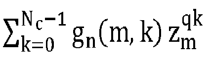


FFT 94 to provide a KST range-Doppler cube 95 which can then be output and used for various radar processing tasks (e.g., detection, angle estimation, clustering, tracking, classification, and fusion). - To provide additional details for an improved contextual understanding of the selected embodiments of the present disclosure, reference is now made to
Figure 10 which depicts a simplified schematic block diagram of an LFM MIMOautomotive radar system 10 which includes an LFM automotive radar front-end device 2 connected between a radar microcontroller processing unit (MCPU) 9 and a transmitantenna array 6 and receiveantenna array 7 in accordance with selected embodiments of the present disclosure. Generally speaking, the overall design of the LFM MIMOautomotive radar system 10 is similar to the LFM MIMOautomotive radar system 1 shown inFigure 1 except that theradar MCPU 9 includes a rangemigration mitigation module 100 that uses a modified Doppler filter 101 tuned to fast-time scaled slow-time frequencies for computing a corrected ADC sample/Doppler spectrum 102 before applying the fast time (range)FFT 103 to compute the range spectrum. In particular, theradar MCPU 9 is connected and configured to receive and digital signal D1 from the LFM automotive radar front-end device 2 for processing by the radar modules 100-103 to generate a range-Doppler cube 15 containing target range, Doppler (radial velocity), angle, and amplitude information in which range migration is eliminated or at least mitigated. In particular, the digital output signals D1 may be processed at the rangemigration mitigation module 100 with a streamlined Keystone Transform by using the modified DFT Doppler filter 101 that is tuned to slow-time frequencies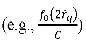

FFT 103 is applied down the fast-time dimension for each range cell to output a range-Doppler map 15 for each receiver channel, all without requiring interpolation operation. In turn, theRDM cube 15 is passed through one or more constant false alarm rate (CFAR)detector modules 16 to obtain the range-Doppler peak detections 17 which are processed by the MIMO arraymeasurement construction module 18 to constructarray measurement vectors 19 for use by the target direction ofarrival estimation module 20 to estimate the direction of arrival for the target return(s). In addition, there are one or more additional radar return data processing steps that may be performed, such as target tracking processing and measurement processing, with the result being output to other automotive computing or user interfacing devices for further process or display. - For an improved understanding of how the range
migration mitigation module 100 computes corrected Doppler spectrums from the ADC samples by applying the modified DFT Doppler filter, the deramp mixer output of the n-th receiver for the k-th chirp is denoted as gn,k (t), where 1 ≤ k ≤ Nc and Nc is the number of chirps. In addition, t denotes the fast-time time variable with each chirp which starts at t = 0 so that t = t 1 , t 2 , ... tNs = [0, 1, 2, ..., Ns - 2, Ns - 1]Ts , where Ns is the number ADC samples acquired per chirp, and where Ts is the sampling interval. Assuming there are L targets, then the deramp mixer output gn,k (t) can be modelled in the following equation:

- For most of the automotive radar use cases, the relative radial motion of the target can be approximated using a simpler linear radial motion model. For example, if τ denotes the slow-time time variable whose value changes at chirp starts to the absolute chirp starting time and remains constant until next chirp start (e.g., τ = (k - 1) ∗ TPRI for (k - 1) ∗ TPRI ≤ t < k ∗ TPRI where TPRI is the time interval between two adjacent chirps' chirp starts), then the roundtrip range function (e.g., the sum of rT,i and rn,i ) can be written in the following simpler format where ṙTi and ṙni indicate the range rates:

- Applying the linear radial motion approximation, the deramp mixer output can be written as the following equation.

- In the above equation, it will be appreciated that, for conventional Keystone Transform approaches, the slow-time variable τ is replaced with a new slow-time variable τ', where

- In order to avoid the challenges involved with computing interpolations, the range
migration mitigation module 100 uses the modified DFT Doppler filter 101 to implement a modified Fourier transform. To this end, the slow-time and fast-time time variables t and τ are discretized such that t = Tsm and τ = TPRIk, where m = 0,1,2, ... Ns - 1 and k = 0,1,2, ... Nc - 1. As a result, the deramp mixer output gn,k (m, k) can be modelled in the following equation which represents the m-th ADC sample of the k-th chirp at the n-th antenna:
- In order to compute an output from the radial-velocity filter (of index q, q = 0,1,2, ...), a modified slow-time Discrete Fourier transform Gn (m,ṙq ) is constructed that represents the output of the q-th modified Doppler filter which is tuned to a radial velocity of ṙq for the m-th ADC sample position and the n-th antenna:

- As depicted, the modified slow-time Discrete Fourier transform Gn (m,ṙq ) is implemented to obtain a range migration mitigated Doppler (or Radial Velocity) spectrum. In particular, it can be observed that, when ṙq = (ṙTi + ṙni )/2, the maximum slow-time coherent integration gain for the i-th target is obtained (which achieves the maximum coherent integration gain of Nc ). In addition, it will be noted that the DFT is tuned to slow-time frequencies (i.e.,


- As this equation demonstrates, the modified Fourier transform coherently integrates the slow-time measurements despite the range migration.
- Upon assuming further that the ṙq term is quantized where ṙq = qΔṙ (where q = 0,1,2, ... Nc), it will be appreciated that the typical quantization step size Δṙ should be no greater than the radial velocity resolution of the system. Setting the quantization to be equal to the resolution,


- In order to apply the modified Discrete Fourier transform filter Gn(m,q), the range
migration mitigation module 100 may be configured to compute the range migration mitigated Doppler (or radial velocity) spectrums for each ADC sampling time, recursively chirp-by-chirp, until last chirp is processed. In particular, for the first chirp (k = 0), the rangemigration mitigation module 100 computes
migration mitigation module 100 computes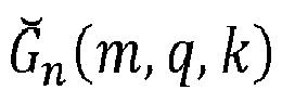
migration mitigation module 100, m = 0,1,2, ... Ns - 1 (where Ns is the number ADC samples acquired per chirp), k = 0,1,2, ... Nc - 1 (where Nc is the number of chirps), q = 0,1,2, ... Nd - 1 (where Nd is the number of Doppler bins and usually Nd = Nc ). In addition, the computation uses known or precomputed values, including Ts (the sampling interval), f 0 (the chirp's center frequency), B (the chirp bandwidth), Tc (the chirp ADC acquisition duration, such that

- As disclose herein, the modified DFT process may be simplified to further streamline the KST process by arranging the modified DFT into the discrete convolution form for implementation in the frequency domain using the convolution theorem. To understand the process of implementing the modified DFT as a convolution computation, reference is made to the following derivation from the modified Doppler filter equation:


- To provide additional details for an improved understanding of selected embodiments of the present disclosure, reference is now made to
Figure 11 which shows a receiver signal processing chain diagram 11 of an LFM pulse doppler radar system which transforms ADC samples using a streamlined Keystone transform process implemented with a time domain convolution-based frequency-scaled discrete Fouriertransform Doppler filter 112. As depicted, a series of NC LFM chirp signals 110 are transmitted, and the resulting target return signals are received and sampled to create an intermediate frequency (IF)ADC cube 111 which includes Ns fast-time samples for NA respective antennas generated by the NC LFM chirps. Instead of starting by correcting the range migration before computing the range and Doppler spectrums, the KST processing is applied to theIF ADC cube 111 by first applying a frequency-scaled time-domain convolution process 112 which implements a frequency-scaled DFT to compute the corrected or focused ADC Doppler cube 113 before computing the KST range-Doppler spectrum 115. For example, the frequency-scaled time-domain convolution process 112 may be configured to use a modified DFT filter where the q-th Doppler DFT filter output of the modified DFT filter


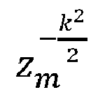
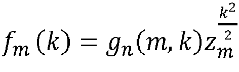
- As disclosed herein, the convolution operation Φ(q) = fm ⊗ hm can be efficiently implemented using (Fast) Fourier Transform and Inverse (Fast) Fourier Transform according to the convolution theorem, as set forth below:

- Because the time-
domain convolution process 112 relies on a Fourier Transform, it can be efficiently implemented using Fast Fourier Transform and Fast Inverse Fourier Transform which are supported by hardware accelerators of many automotive radar microprocessor chips. - Having applied the time-
domain convolution process 112, the focused ADC Doppler cube 113 is generated to provide the range-migration mitigated Doppler spectrum for each ADC sample across the slow-time. The next processing step is to generate the range spectrum for each Doppler cell. Since the effect of range migration is removed at this point, the focused ADC Doppler cube 113 may be processed with a first fast-time (range) FFT 114 to provide a KST range-Doppler cube 115 which can then be output and used for various radar processing tasks (e.g., detection, angle estimation, clustering, tracking, classification, and fusion). In particular, the fast-time Discrete Fourier Transform of Gn (m,q) tuned to rp may be implemented as the following equation where

- In this equation, when rp = (rTi + rni )/2 (for an i-th target), the maximum fast-time coherent integration gain (Ns ) is achieved for the target and a range spectrum peak corresponding to the range of the target is obtained.
- Upon assuming that rp is quantized where rp = Δr(p - 1), the equation


- As seen from the foregoing, the equation


- In practice, all of the Discrete Fourier Transform processes can be carried out using Fast Fourier Transform; however, the integer-2π periodic spectrum ambiguities need to be handled properly if any target's radial velocity cannot be sampled unambiguously.
- In similar fashion, the modified DFT process may be simplified to implement the streamlined KST process in the time domain using the convolution theorem. To provide additional details for an improved understanding of selected embodiments of the present disclosure, reference is now made to
Figure 12 which shows a receiver signal processing chain diagram 12 of an LFM pulse doppler radar system which transforms ADC samples using a streamlined Keystone transform process implemented with a frequency domain convolution-based frequency-scaled discrete Fouriertransform Doppler filter 122. As depicted, a series of NC LFM chirp signals 120 are transmitted, and the resulting target return signals are received and sampled to create an intermediate frequency (IF)ADC cube 121 which includes Ns fast-time samples for NA respective antennas generated by the NC LFM chirps. Next, theIF ADC cube 121 is processed by applying a frequency-scaled frequency-domain convolution process 122 which implements a frequency-scaled DFT to compute the corrected or focusedADC Doppler cube 123 before computing the KST range-Doppler spectrum 125. For example, the frequency-scaled frequency-domain convolution process 122 may be is configured to use a modified DFT filter where the q-th Doppler DFT filter output of the modified DFT filter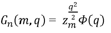


ADC Doppler cube 123 may then be processed with a first fast-time (range) FFT 124 to provide a KST range-Doppler cube 125 which can then be output and used for various radar processing tasks (e.g., detection, angle estimation, clustering, tracking, classification, and fusion). - Because the frequency-
domain convolution process 122 relies on Fourier Transform, it can be efficiently implemented using Fast Fourier Transform and Fast Inverse Fourier Transform which are supported by hardware accelerators of many automotive radar microprocessor chips. - In order to validate the effectiveness of the range migration DSP processes disclosed herein, reference is now made to
Figure 13 shows simulated range migration effects of a single constant-radial velocity range migrating target, including a simulated range-chirp map 13A, range-doppler map 13B, and ADC sample-Doppler map 13C before migration, along with a simulated range-chirp map 13D, range-doppler map 13E, and ADC sample-Doppler map 13F after migration. Starting withFigures 13A-C , there are depicted simulations for a constant-radial velocity target resulting in significant range migration. In particular,Figure 13A depict the range spectrum output (horizontal slices) as function of chirps or PRIs (vertical axis). The bright colors indicate strong amplitudes, and the slantedprofile line 131 shows that the range is migrating from the 26th to the 34th range cell across the 128 chirps. The range migration effect can also be observed in the simulated ADC sample-Doppler map 13C where the slantedline 133 which shows that the range rate varies from the 74th range rate cell to the 82nd range rate cell across the 600 ADC samples. Due to the range migration, the resulting range-Doppler response is smeared as expected (with reduced SNR and widened peak) as depicted inFigure 13B with the smearedregion 132. - The result of the mitigation is depicted in the simulations shown in
Figures 13D-F . In particular,Figure 13F depicts the effectiveness of the first step of using a modified DFT filter to compute the Doppler spectrum where thehorizontal profile line 136 shows that the migration of the range rate is removed. In addition,Figure 13E illustrates that, in the next step of computing the range spectrum, thetarget 135 is refocused on the range-Doppler map. While the range-chirp map ofFigure 13D is not required of the proposed process, it is produced here from the focused range-Doppler map 13E as a reference to demonstrate that the range migration effect is also removed, resulting in avertical line 134 having a constant range value aligned to the start of the chirp sequence, which is at the 26th range cell. - To provide additional details for an improved understanding of selected embodiments of the present disclosure, reference is now made to
Figure 14 which illustrates a simplified architectural block diagram of amicrocontroller system 14 for automotive and industrial high-performance radar applications which implements range migration mitigation using a modified Doppler filter tuned to scaled and fast time-dependent frequencies. As depicted, themicrocontroller system 14 includes one or more control processor or central processing unit (CPU)subsystems 1401, on-chip memory 1402 (e.g., volatile or non-volatile memory), andradar processing platform 1403 for providing radar-specific high throughput signal processing. For example, theradar processing platform 1403 may include one or more digital signal processor (DSP)cores 1404, one or more radarprocessing hardware accelerators 1405, achirp generator 1406, and atransceiver interface 1407 to provide transmit and receive module control and processing. The processor(s) 1401, on-chip memory 1402, andradar processing platform 1403 may be connected over an on-chip interconnect 1410 to amemory interface 1411, (e.g., DDR interface), one or more connectivity modules 1412 (e.g., PCIe 2x, FlexPWM, eTimer, IIC, DSPI, etc.), andother modules 1413. In selected embodiments, themicrocontroller system 14 may be implemented as circuitry on a single integrated circuit or system-on-chip (SoC). In addition, theinterconnect 1410 can be any type of bus structure, including but not limited to a non-coherent interconnect, an advanced high-performance bus (AHB), or an advanced peripheral bus (APB). In addition, the control processor(s) 1401 may be any type of processing circuit, including but not limited to a microprocessor (MPU), microcontroller (MCU), digital signal processor (DSP), or another type of processor or processor core with multiple levels of cache memory. Though not shown, themicrocontroller system 14 may include peripheral devices or special-purpose processors, communication interfaces, timers, encoders/decoders, and one or more external memory interfaces, such as DDR interface or flash interface. In turn, the external memory interfaces may be connected to external memory, such as DDR memory or flash memory. - As disclosed, the
microcontroller system 14 may use the control processor(s) 1401 to provide a signal processing toolbox (SPT) which receives digital output signals from theradar processing platform 1403 which uses the modules 1404-1007 to process received radar return signals by applying signal conditioning (e.g., low noise amplification, low/high pass filtering, and analog-to-digital conversion) and signal analysis (e.g., gain, windowing, FFT, and filtering). The resulting digital output signals are then processed by the control processor(s) 1401 for detection and tracking to detect one or more targets. In particular, the control processor(s) 1401 may execute control code instructions and/or hardware for performing a frequency-scaled DFT 1420 on digital samples of the received and de-ramp-mixed chirp signals to extract focused ADC-Doppler cute information. Alternatively, the control processor(s) 1401 may execute control code instructions and/or hardware for performing a time-domain convolution 1421 on digital samples of the received and de-ramp-mixed chirp signals to extract focused ADC-Doppler cute information. Alternatively, the control processor(s) 1401 may execute control code instructions and/or hardware for performing a frequency-domain convolution 1422 on digital samples of the received and de-ramp-mixed chirp signals to extract focused ADC-Doppler cute information. In addition, the control processor(s) 1401 may execute control code instructions and/or hardware for performing a short-time FFT or long-time FFT 1423 on the focused ADC-Doppler cute information to extract KST range-Doppler cube information. - To provide additional details for an improved understanding of selected embodiments of the present disclosure, reference is now made to
Figure 15 which illustrates asimplified flow chart 15 showing the logic for implementing range migration mitigation with a Keystone transformation process using Doppler filtering tuned to scaled and fast time-dependent frequencies. In an example embodiment, the control logic and methodology shown inFigure 15 may be implemented with a combination of hardware and software on a radar controller processor which directly filters ADC samples using a modified DFT Doppler filter that is tuned to fast-time scaled, slow-time frequencies. In selected embodiments, a modified DFT Doppler process can be streamlined by arranging the modified DFT into a discrete convolution form that may be implemented in the frequency domain by using a hardware-accelerated Fast Fourier Transform (FFT) and Inverse Fast Fourier Transform (IFFT) engine, thereby achieving improved computational efficiency and speed. - The process starts (step 1501), such as when the radar system begins the process of sensing the location and movement of one or more target objects using transmit radar signals that are sent over a plurality of transmit antennas. To generate the transmit radar signals, the radar system first generates a reference chirp signal (step 1502), such as by periodically modulating a transmit radar signal with a frequency and/or phase shift. For example, with automotive Frequency Modulation Continuous Wave (FMCW) radars, the reference chirp signal may be generated as a Linear Frequency Modulation (LFM) waveform that is distributed to a plurality of transmit channel circuits which are respectively associated with a plurality of transmit antennas.
- At
step 1503, the chirp signals are conditioned and amplified for transmission over the corresponding transmit channel circuits. In selected embodiments, this processing is performed by the transmit channel circuits which each include an RF conditioning module (which filters the chirp signal) and power amplifier (which amplifies the RF conditioning module output for transmission over a corresponding transmit antenna). In embodiments where time-domain modulation is used in combination with the frequency/phase offset modulation, the non-adjacent transmit channel circuits may be controlled to sequentially condition and amplify transmit radar waveforms from non-adjacent transmit antennas. For example, the radar transmit channel circuits may transmit LFM pulses from one or more transmit antennas. - At
step 1504, each receiver channel may receive and amplify the target-reflected reference chirp signals at one or more receive antennas. In selected embodiments, one or more receive antennas at the receiver module receive target returns from the transmitted reference chirp signal waveforms as (radio frequency) antenna signals for subsequent amplification, such as by using a low noise amplifier to generate an amplified RF signal from the target returns. - At
step 1505, each receiver channel may mix the amplified transmit channel signals with the reference chirp signal at the receiver to generate an intermediate frequency (IF) signal. In selected embodiments, the mixing step may be implemented by applying the reference chirp signal to a receiver module mixer (or deramp mixer) which is also connected to receive the amplified transmit channel signals for mixing with the reference chirp signal, thereby generating an intermediate frequency signal. - At
step 1506, each receiver channel may condition the intermediate frequency signal for digital conversion. In selected embodiments, the conditioning process includes at least feeding the intermediate frequency signal to a bandpass-pass filter, alone or in combination with additional programmable gain and/or filtering steps, thereby generating a bandpass-filtered signal. - At
step 1507, each receiver channel may digitize the bandpass-filtered conditioned IF signal, such as by using a high-speed analog/digital converter (ADC) to generate ADC samples for output as a digital signal output that is suitable for digital processing. In automotive radar applications which use a deramp mixer to mix the received signal with transmitted signal before analog-to-digital conversion, there is no down-conversion and Nyquist sampling of the received signal which would require very high ADC sampling rates (e.g., GHz sampling rates), so a lower ADC sampling rate can be used (e.g., tens of MHz). - At
step 1508, the radar controller performs range migration mitigation processing on the digital signal using a modified Doppler filter that is tuned to fast-time scaled slow-time frequencies, thereby generating a Doppler compressed signal. As a preliminary step range migration mitigation processing, the radar controller may be configured to construct an ADC sample-chirp-antenna cube (raw data cube) for each frame by storing store the ADC samples sample-by-sample over fast time and chirp-by-chirp over slow-time for each Rx antenna. In addition, the radar controller may be configured to process each raw data cube by performing modified Doppler filtering, for each ADC sample position, down the slow-time dimension, using a plurality of modified DFT Doppler filters which are each tuned to a slow-time frequency as a function of a desired target detection radial velocity and a scaling factor which is a function of the current fast-time ADC sample's sampling time relative to the chirp acquisition start time. As a result of performing modified Doppler filtering of each fast-time ADC sample position and all antennas in the raw data cube, the radar controller generates and outputs a range migration free ADC sample-Doppler-antenna cube. - At
step 1509, the radar controller performs digital FFT processing on the ADC sample-Doppler-antenna cube to generate a range compressed signal. In selected embodiments, the radar controller is configured to process the ADC sample-Doppler-antenna cube by computing the range spectrum for each Doppler cell position, down the fast-time dimension compute the range spectrum using any spectral analysis method, such as FFT. As a result of performing FFT processing of each Doppler cell position and all antennas in the ADC sample-Doppler-antenna cube, the radar controller generates and outputs a range migration free range-Doppler-antenna cube. - Subsequently, the radar controller processes each range migration free range-Doppler-antenna cube to extract high-quality range and angular information on one or more targets, such as by performing CFAR detection processing (step 1510), MIMO virtual array construction (step 1511), and targe direction of arrival estimation (step 1512) to obtain the final target information, including range, Doppler (radial velocity), angle(s), and amplitude, etc. The target information may then be output to subsequent perception processing such as clustering, centroiding, tracking, perception-level target detection, target classification, and sensor fusion. The output of the perception is fed to other automotive systems such as ADAS, autonomous diving path planning and drive control, and user displays and data logging.
- As disclosed herein, an LFM radar system is provided which implements a highly efficient Keystone Transform for mitigating range migration by operating directly on ADC samples with a modified DFT Doppler filter. By using FFT and IFFT hardware accelerators to operate directly on the fast-time ADC samples out of the deramp mixer in the time domain, KST processing can be performed in the time or frequency domain without explicit interpolation. In addition, the streamlined KST processing disclosed herein does not require very high ADC sampling rates, nor is there a requirement to first perform matched filtering processing upon samples to obtain fast-time range response before performing KST processing.
- By now it should be appreciated that there has been provided a linear chirp radar system, device, and method of operation. The disclosed radar system includes a radio-frequency (RF) transmitter unit and first plurality of transmit antennas which are connected to transmit linear chirp radar signals in a sequence of transmit frames. The disclosed radar system also includes an RF receiver unit and a first plurality of receive antennas which are connected to generate analog-to-digital (ADC) sample signals from one or more target return signals received in response to the linear chirp radar signals. In addition, the disclosed radar system includes a radar control processing unit connected and configured to control the RF transmitter unit and the RF receiver unit. As disclosed, the radar control processing unit is configured to mitigate range migration by directly filtering the ADC samples using a modified Doppler filter that is tuned to fast-time scaled, slow-time frequencies to generate a focused ADC Doppler cube, and by applying a Fourier Transform on each Doppler cell in the focused ADC Doppler cube to generate a focused range-Doppler cube. In selected embodiments, the radar control processing unit may be configured to apply the Fourier Transform by performing Doppler fast Fourier transform (FFT) on ADC samples in the focused ADC Doppler cube to generate a range spectrum from each Doppler bin sample in the focused ADC Doppler cube. In other embodiments, the radar control processing unit is configured to generate, from the ADC sample signals, an ADC sample-chirp antenna cube for each transmit frame. In such embodiments, the radar control processing unit may be configured to directly filter the ADC samples by computing range migration mitigated Doppler spectrums for each ADC sample in the ADC sample-chirp antenna cube, recursively chirp-by-chirp until a last chirp is processed. In selected embodiments, the radar control processing unit is configured to directly filter the ADC samples by applying a frequency-scaled discrete Fourier Transform (DFT) Doppler filter which computes a time-domain convolution from the ADC samples. In other embodiments, the radar control processing unit is configured to directly filter the ADC samples by applying a frequency-scaled discrete Fourier Transform (DFT) Doppler filter which computes a frequency-domain convolution from the ADC samples. In either case, the radar control processing unit may be configured to compute the time-domain convolution or the frequency-domain convolution from the ADC samples using a Fast Fourier Transform hardware accelerator and an Inverse Fast Fourier Transform hardware accelerator.
- In another form, there is provided a method for operating a radar system and device. In the disclosed methodology, linear chirp radar signals are transmitted in a sequence of transmit frames from a first plurality of transmit antennas. In addition, the disclosed methodology generates analog-to-digital (ADC) sample signals from one or more target return signals received at a first plurality of receive antennas in response to the linear chirp radar signals. The disclosed methodology also processes the ADC sample signals at a radar control processing unit that is connected and configured to mitigate range migration in the ADC sample signals by directly filtering the ADC samples using a modified Doppler filter that is tuned to fast-time scaled, slow-time frequencies to generate a focused ADC Doppler cube, and by applying a Fourier Transform on each Doppler cell in the focused ADC Doppler cube to generate a focused range-Doppler cube. In selected embodiments, the ADC sample signals are processed by generating, from the ADC sample signals, an ADC sample-chirp antenna cube for each transmit frame. In such embodiments, the ADC samples are directly filtered by computing range migration mitigated Doppler spectrums for each ADC sample in the ADC sample-chirp antenna cube, recursively chirp-by-chirp until a last chirp is processed. In other embodiments, the Fourier Transform is applied on each Doppler cell by performing Doppler fast Fourier transform (FFT) on ADC samples in the focused ADC Doppler cube to generate a range spectrum from each Doppler bin sample in the focused ADC Doppler cube. In selected embodiments, the ADC samples are directly filtered by applying a frequency-scaled discrete Fourier Transform (DFT) Doppler filter which computes a time-domain convolution from the ADC samples. In such embodiments, the frequency-scaled discrete DFT Doppler filter is applied by computing the time-domain convolution from the ADC samples using a Fast Fourier Transform hardware accelerator and an Inverse Fast Fourier Transform hardware accelerator. In selected embodiments, the ADC samples are directly filtered by applying a frequency-scaled discrete Fourier Transform (DFT) Doppler filter which computes a frequency-domain convolution from the ADC samples. In such embodiments, the frequency-scaled discrete DFT Doppler filter is applied by computing the frequency-domain convolution from the ADC samples using a Fast Fourier Transform hardware accelerator and an Inverse Fast Fourier Transform hardware accelerator.
- In yet another form, there is provided a radar apparatus and associated method of operation. In the disclosed radar apparatus, a plurality of transmitter modules is configured to transmit a plurality of linear chirp waveforms in a sequence of transmit frames. The radar apparatus also includes at least a first receiver module connected and configured to receive one or more target return signals reflected from the plurality of linear chirp waveforms by at least one target and to generate analog-to-digital (ADC) sample signals from one or more target return signals. In addition, the radar apparatus includes a radar control processing unit connected and configured to control the plurality of transmitter modules and at least the first receiver module to mitigate range migration by directly filtering the ADC samples using a modified Doppler filter that is tuned to fast-time scaled, slow-time frequencies to generate a focused ADC Doppler cube, and by applying a Fourier Transform on each Doppler cell in the focused ADC Doppler cube to generate a focused range-Doppler cube. In selected embodiments, the radar control processing unit is configured to apply the Fourier Transform by performing Doppler fast Fourier transform (FFT) on ADC samples in the focused ADC Doppler cube to generate a range spectrum from each Doppler bin sample in the focused ADC Doppler cube. In other embodiments, the radar control processing unit is configured to directly filter the ADC samples by applying a frequency-scaled discrete Fourier Transform (DFT) Doppler filter which computes a time-domain convolution from the ADC samples using a Fast Fourier Transform hardware accelerator and an Inverse Fast Fourier Transform hardware accelerator. In other embodiments, the radar control processing unit is configured to directly filter the ADC samples by applying a frequency-scaled discrete Fourier Transform (DFT) Doppler filter which computes a frequency-domain convolution from the ADC samples using a Fast Fourier Transform hardware accelerator and an Inverse Fast Fourier Transform hardware accelerator.
- Although the described exemplary embodiments disclosed herein focus on example automotive radar circuits, systems, and methods for using same, the present invention is not necessarily limited to the example embodiments illustrate herein. For example, various embodiments of the range migration mitigation processing may be applied in non-automotive applications, and may use additional or fewer circuit components than those specifically set forth. Thus, the particular embodiments disclosed above are illustrative only and should not be taken as limitations upon the present invention, as the invention may be modified and practiced in different but equivalent manners apparent to those skilled in the art having the benefit of the teachings herein. Accordingly, the foregoing description is not intended to limit the invention to the particular form set forth, but on the contrary, is intended to cover such alternatives, modifications and equivalents as may be included within the scope of the invention as defined by the appended claims so that those skilled in the art should understand that they can make various changes, substitutions and alterations without departing from the spirit and scope of the invention in its broadest form.
- Benefits, other advantages, and solutions to problems have been described above with regard to specific embodiments. However, the benefits, advantages, solutions to problems, and any element(s) that may cause any benefit, advantage, or solution to occur or become more pronounced are not to be construed as a critical, required, or essential feature or element of any or all the claims. In addition, it will be appreciated that references to a functional "unit" or "module" or "block" may be implemented in whole or in part with hardware circuits or circuitry, alone or in combination with processor-implemented control logic in one or more integrated circuits (chips). As used herein, the terms "comprises," "comprising," or any other variation thereof, are intended to cover a non-exclusive inclusion, such that a process, method, article, or apparatus that comprises a list of elements does not include only those elements but may include other elements not expressly listed or inherent to such process, method, article, or apparatus.
Claims (15)
- A radar system, comprising:a radio-frequency, RF, transmitter unit and first plurality of transmit antennas which are connected to transmit linear chirp radar signals in a sequence of transmit frames;an RF receiver unit and a first plurality of receive antennas which are connected to generate analog-to-digital, ADC, sample signals from one or more target return signals received in response to the linear chirp radar signals; anda radar control processing unit connected and configured to control the RF transmitter unit and the RF receiver unit to mitigate range migration by directly filtering the ADC samples using a modified Doppler filter that is tuned to fast-time scaled, slow-time frequencies to generate a focused ADC Doppler cube, and by applying a Fourier Transform on each Doppler cell in the focused ADC Doppler cube to generate a focused range-Doppler cube.
- The radar system of claim 1, wherein the radar control processing unit is configured to generate, from the ADC sample signals, an ADC sample-chirp antenna cube for each transmit frame.
- The radar system of claim 2, wherein the radar control processing unit is configured to directly filter the ADC samples by computing range migration mitigated Doppler spectrums for each ADC sample in the ADC sample-chirp antenna cube, recursively chirp-by-chirp until a last chirp is processed.
- The radar system of any preceding claim, wherein the radar control processing unit is configured to apply the Fourier Transform by performing Doppler fast Fourier transform, FFT, on ADC samples in the focused ADC Doppler cube to generate a range spectrum from each Doppler bin sample in the focused ADC Doppler cube.
- The radar system of any preceding claim, wherein the radar control processing unit is configured to directly filter the ADC samples by applying a frequency-scaled discrete Fourier Transform, DFT Doppler filter which computes a time-domain convolution from the ADC samples.
- The radar system of claim 5, wherein the radar control processing unit is configured to compute the time-domain convolution from the ADC samples using a Fast Fourier Transform hardware accelerator and an Inverse Fast Fourier Transform hardware accelerator.
- The radar system of any preceding claim, wherein the radar control processing unit is configured to directly filter the ADC samples by applying a frequency-scaled discrete Fourier Transform, DFT, Doppler filter which computes a frequency-domain convolution from the ADC samples.
- The radar system of claim 7, wherein the radar control processing unit is configured to compute the frequency-domain convolution from the ADC samples using a Fast Fourier Transform hardware accelerator and an Inverse Fast Fourier Transform hardware accelerator.
- A method for operating a radar system, comprising:transmitting linear chirp radar signals in a sequence of transmit frames from a first plurality of transmit antennas;generating analog-to-digital, ADC, sample signals from one or more target return signals received at a first plurality of receive antennas in response to the linear chirp radar signals; andprocessing the ADC sample signals at a radar control processing unit connected and configured to mitigate range migration in the ADC sample signals by directly filtering the ADC samples using a modified Doppler filter that is tuned to fast-time scaled, slow-time frequencies to generate a focused ADC Doppler cube, and by applying a Fourier Transform on each Doppler cell in the focused ADC Doppler cube to generate a focused range-Doppler cube.
- The method of claim 9, wherein processing the ADC sample signals comprises generating, from the ADC sample signals, an ADC sample-chirp antenna cube for each transmit frame.
- The method of claim 10, wherein directly filtering the ADC samples comprises computing range migration mitigated Doppler spectrums for each ADC sample in the ADC sample-chirp antenna cube, recursively chirp-by-chirp until a last chirp is processed.
- The method of any of claims 9 to 11, wherein directly filtering the ADC samples comprises applying a frequency-scaled discrete Fourier Transform, DFT, Doppler filter which computes a time-domain convolution from the ADC samples.
- The method of claim 12, wherein applying the frequency-scaled discrete DFT Doppler filter comprises computing the time-domain convolution from the ADC samples using a Fast Fourier Transform hardware accelerator and an Inverse Fast Fourier Transform hardware accelerator.
- The method of any of claims 9 to 11, wherein directly filtering the ADC samples comprises applying a frequency-scaled discrete Fourier Transform, DFT, Doppler filter which computes a frequency-domain convolution from the ADC samples.
- The method of claim 14, applying the frequency-scaled discrete DFT Doppler filter comprises computing the frequency-domain convolution from the ADC samples using a Fast Fourier Transform hardware accelerator and an Inverse Fast Fourier Transform hardware accelerator.
Applications Claiming Priority (1)
| Application Number | Priority Date | Filing Date | Title |
|---|---|---|---|
| US17/715,520 US12320920B2 (en) | 2022-04-07 | 2022-04-07 | Automotive radar with range migration mitigation capability |
Publications (2)
| Publication Number | Publication Date |
|---|---|
| EP4258010A1 true EP4258010A1 (en) | 2023-10-11 |
| EP4258010B1 EP4258010B1 (en) | 2026-01-28 |
Family
ID=85873612
Family Applications (1)
| Application Number | Title | Priority Date | Filing Date |
|---|---|---|---|
| EP23166487.1A Active EP4258010B1 (en) | 2022-04-07 | 2023-04-04 | Automotive radar with range migration mitigation capability |
Country Status (3)
| Country | Link |
|---|---|
| US (1) | US12320920B2 (en) |
| EP (1) | EP4258010B1 (en) |
| CN (1) | CN116893389A (en) |
Cited By (1)
| Publication number | Priority date | Publication date | Assignee | Title |
|---|---|---|---|---|
| DE102023209872A1 (en) * | 2023-10-10 | 2025-04-10 | Zf Friedrichshafen Ag | Method for determining the true speed of a target object detected by radar measurement of an FMCW radar within a single measurement cycle using range migration |
Families Citing this family (6)
| Publication number | Priority date | Publication date | Assignee | Title |
|---|---|---|---|---|
| US20230408671A1 (en) * | 2022-06-17 | 2023-12-21 | Uhnder, Inc. | System and method for fast frequency hopping waveforms with continuous phase modulation in radar systems |
| EP4390456A1 (en) * | 2022-12-19 | 2024-06-26 | Aptiv Technologies Limited | Beamvector filtering and disambiguation using velocity profile pattern for low level radar ego-motion |
| US20250189658A1 (en) * | 2023-12-11 | 2025-06-12 | Automotive Research & Testing Center | Sensor fusion and object tracking system and method thereof |
| CN121231856A (en) * | 2024-06-27 | 2025-12-30 | 加特兰微电子科技(上海)有限公司 | Signal processing methods, integrated circuits, electromagnetic wave sensors, devices and media |
| US20260003060A1 (en) * | 2024-06-28 | 2026-01-01 | Intel Corporation | Methods and devices for range-doppler processing |
| US20260063793A1 (en) * | 2024-08-30 | 2026-03-05 | Nxp B.V. | Radar Data Compression Using Hybrid Spectral Transformation |
Citations (1)
| Publication number | Priority date | Publication date | Assignee | Title |
|---|---|---|---|---|
| EP3835810A1 (en) * | 2019-12-09 | 2021-06-16 | NXP USA, Inc. | Method and system for frequency offset modulation range division mimo automotive radar |
Family Cites Families (6)
| Publication number | Priority date | Publication date | Assignee | Title |
|---|---|---|---|---|
| DE19757309C1 (en) * | 1997-12-22 | 1999-07-15 | Deutsch Zentr Luft & Raumfahrt | Process for processing Spotlight SAR raw data |
| CN104062640B (en) | 2014-06-30 | 2016-03-30 | 北京理工大学 | The Fast implementation that a kind of external illuminators-based radar range migration compensates |
| US10330773B2 (en) * | 2016-06-16 | 2019-06-25 | Texas Instruments Incorporated | Radar hardware accelerator |
| CN106950550B (en) * | 2017-03-31 | 2020-03-03 | 中国人民解放军海军航空大学 | On-line estimation method of high dynamic bias based on cross-fuzzy interval judgment under the condition of fuzzy distance measurement and speed measurement |
| US20190056478A1 (en) * | 2017-08-15 | 2019-02-21 | Valeo Radar Systems, Inc. | Frequency Domain MIMO For FMCW Radar |
| US10451712B1 (en) * | 2019-03-11 | 2019-10-22 | Plato Systems, Inc. | Radar data collection and labeling for machine learning |
-
2022
- 2022-04-07 US US17/715,520 patent/US12320920B2/en active Active
-
2023
- 2023-04-03 CN CN202310343537.7A patent/CN116893389A/en active Pending
- 2023-04-04 EP EP23166487.1A patent/EP4258010B1/en active Active
Patent Citations (1)
| Publication number | Priority date | Publication date | Assignee | Title |
|---|---|---|---|---|
| EP3835810A1 (en) * | 2019-12-09 | 2021-06-16 | NXP USA, Inc. | Method and system for frequency offset modulation range division mimo automotive radar |
Non-Patent Citations (1)
| Title |
|---|
| XU LUZHOU ET AL: "Doppler-Range Processing for Enhanced High-Speed Moving Target Detection Using LFMCW Automotive Radar", IEEE TRANSACTIONS ON AEROSPACE AND ELECTRONIC SYSTEMS., vol. 58, no. 1, 1 February 2022 (2022-02-01), US, pages 568 - 580, XP055965785, ISSN: 0018-9251, Retrieved from the Internet <URL:https://ieeexplore.ieee.org/ielx7/7/9709174/09506841.pdf?tp=&arnumber=9506841&isnumber=9709174&ref=aHR0cHM6Ly9pZWVleHBsb3JlLmllZWUub3JnL2Fic3RyYWN0L2RvY3VtZW50Lzk1MDY4NDE=> [retrieved on 20220201], DOI: 10.1109/TAES.2021.3101768 * |
Cited By (2)
| Publication number | Priority date | Publication date | Assignee | Title |
|---|---|---|---|---|
| DE102023209872A1 (en) * | 2023-10-10 | 2025-04-10 | Zf Friedrichshafen Ag | Method for determining the true speed of a target object detected by radar measurement of an FMCW radar within a single measurement cycle using range migration |
| DE102023209872B4 (en) * | 2023-10-10 | 2025-11-27 | Zf Friedrichshafen Ag | Method for determining the true velocity of a target object detected by radar measurement of an FMCW radar within a single measurement cycle using range migration |
Also Published As
| Publication number | Publication date |
|---|---|
| US12320920B2 (en) | 2025-06-03 |
| US20230324509A1 (en) | 2023-10-12 |
| CN116893389A (en) | 2023-10-17 |
| EP4258010B1 (en) | 2026-01-28 |
Similar Documents
| Publication | Publication Date | Title |
|---|---|---|
| EP4258010B1 (en) | Automotive radar with range migration mitigation capability | |
| EP4187275B1 (en) | Cfar phased array pre-processing using noncoherent and coherent integration in automotive radar systems | |
| US10754008B2 (en) | Vehicle radar system that addresses doppler frequency shift and method of using the same | |
| US11525908B2 (en) | Radar apparatuses and methods involving determination of velocity of an object | |
| US10830869B2 (en) | Vehicle radar system and method of calibrating the same | |
| US10627481B2 (en) | Multi-resolution doppler processing | |
| EP4253992A1 (en) | Automotive radar and method for target detection | |
| USH1720H (en) | Time frequency processor for radar imaging of moving targets | |
| EP4372416A1 (en) | Super-resolution mimo sparse array automotive radar based on forward and backward hankel matrix completion | |
| US12422538B2 (en) | Efficient direction of arrival estimation using low rank approximation | |
| EP2942641A1 (en) | Radar device | |
| US12153125B2 (en) | Radar system and method for performing direction of arrival estimation in a radar system | |
| EP4202489A1 (en) | Parameter defined stepped frequency waveform for radar | |
| US20210011146A1 (en) | Object position and movement estimation using radar | |
| US20240402324A1 (en) | Mimo radar apparatus and mimo radar method | |
| EP4095558A2 (en) | Radar communications with oversampling | |
| US20230408640A1 (en) | System and method for radar range walk compensation in radar systems | |
| CN119001700A (en) | Method and apparatus for processing joint multiple chirp sequences | |
| US20240280692A1 (en) | Fine-near-range estimation method for automotive radar applications | |
| EP4579280A1 (en) | Radar signal direction of arrival super-resolution estimation | |
| US20240345238A1 (en) | Method and apparatus for estimating a direction of arrival | |
| US20250093489A1 (en) | Radar interference mitigation and target radar data gap filling | |
| EP4258008A1 (en) | Adaptive tx-rx crosstalk cancellation for radar systems | |
| Nagano et al. | Fractional Range Migration Compensation and Doppler Ambiguity Resolution for Pulse Doppler Radars Using Variable Chirp Rate Signals and Pulse Compression With Partial Reference Signals |
Legal Events
| Date | Code | Title | Description |
|---|---|---|---|
| PUAI | Public reference made under article 153(3) epc to a published international application that has entered the european phase |
Free format text: ORIGINAL CODE: 0009012 |
|
| STAA | Information on the status of an ep patent application or granted ep patent |
Free format text: STATUS: THE APPLICATION HAS BEEN PUBLISHED |
|
| AK | Designated contracting states |
Kind code of ref document: A1 Designated state(s): AL AT BE BG CH CY CZ DE DK EE ES FI FR GB GR HR HU IE IS IT LI LT LU LV MC ME MK MT NL NO PL PT RO RS SE SI SK SM TR |
|
| STAA | Information on the status of an ep patent application or granted ep patent |
Free format text: STATUS: REQUEST FOR EXAMINATION WAS MADE |
|
| 17P | Request for examination filed |
Effective date: 20240411 |
|
| RBV | Designated contracting states (corrected) |
Designated state(s): AL AT BE BG CH CY CZ DE DK EE ES FI FR GB GR HR HU IE IS IT LI LT LU LV MC ME MK MT NL NO PL PT RO RS SE SI SK SM TR |
|
| GRAP | Despatch of communication of intention to grant a patent |
Free format text: ORIGINAL CODE: EPIDOSNIGR1 |
|
| STAA | Information on the status of an ep patent application or granted ep patent |
Free format text: STATUS: GRANT OF PATENT IS INTENDED |
|
| INTG | Intention to grant announced |
Effective date: 20250919 |
|
| GRAS | Grant fee paid |
Free format text: ORIGINAL CODE: EPIDOSNIGR3 |
|
| GRAA | (expected) grant |
Free format text: ORIGINAL CODE: 0009210 |
|
| STAA | Information on the status of an ep patent application or granted ep patent |
Free format text: STATUS: THE PATENT HAS BEEN GRANTED |
|
| AK | Designated contracting states |
Kind code of ref document: B1 Designated state(s): AL AT BE BG CH CY CZ DE DK EE ES FI FR GB GR HR HU IE IS IT LI LT LU LV MC ME MK MT NL NO PL PT RO RS SE SI SK SM TR |
|
| REG | Reference to a national code |
Ref country code: CH Ref legal event code: F10 Free format text: ST27 STATUS EVENT CODE: U-0-0-F10-F00 (AS PROVIDED BY THE NATIONAL OFFICE) Effective date: 20260128 Ref country code: GB Ref legal event code: FG4D |
|
| REG | Reference to a national code |
Ref country code: DE Ref legal event code: R096 Ref document number: 602023011154 Country of ref document: DE |
|
| REG | Reference to a national code |
Ref country code: IE Ref legal event code: FG4D |
|
| PGFP | Annual fee paid to national office [announced via postgrant information from national office to epo] |
Ref country code: FR Payment date: 20260320 Year of fee payment: 4 |
|
| REG | Reference to a national code |
Ref country code: NL Ref legal event code: MP Effective date: 20260128 |
|
| PG25 | Lapsed in a contracting state [announced via postgrant information from national office to epo] |
Ref country code: NL Free format text: LAPSE BECAUSE OF FAILURE TO SUBMIT A TRANSLATION OF THE DESCRIPTION OR TO PAY THE FEE WITHIN THE PRESCRIBED TIME-LIMIT Effective date: 20260128 |
|
| REG | Reference to a national code |
Ref country code: AT Ref legal event code: MK05 Ref document number: 1881953 Country of ref document: AT Kind code of ref document: T Effective date: 20260128 |
|
| PG25 | Lapsed in a contracting state [announced via postgrant information from national office to epo] |
Ref country code: RS Free format text: LAPSE BECAUSE OF FAILURE TO SUBMIT A TRANSLATION OF THE DESCRIPTION OR TO PAY THE FEE WITHIN THE PRESCRIBED TIME-LIMIT Effective date: 20260428 |
|
| PG25 | Lapsed in a contracting state [announced via postgrant information from national office to epo] |
Ref country code: ES Free format text: LAPSE BECAUSE OF FAILURE TO SUBMIT A TRANSLATION OF THE DESCRIPTION OR TO PAY THE FEE WITHIN THE PRESCRIBED TIME-LIMIT Effective date: 20260128 |
|
| PG25 | Lapsed in a contracting state [announced via postgrant information from national office to epo] |
Ref country code: PL Free format text: LAPSE BECAUSE OF FAILURE TO SUBMIT A TRANSLATION OF THE DESCRIPTION OR TO PAY THE FEE WITHIN THE PRESCRIBED TIME-LIMIT Effective date: 20260128 |
|
| PG25 | Lapsed in a contracting state [announced via postgrant information from national office to epo] |
Ref country code: GR Free format text: LAPSE BECAUSE OF FAILURE TO SUBMIT A TRANSLATION OF THE DESCRIPTION OR TO PAY THE FEE WITHIN THE PRESCRIBED TIME-LIMIT Effective date: 20260429 |
|
| REG | Reference to a national code |
Ref country code: LT Ref legal event code: MG9D |
|
| PG25 | Lapsed in a contracting state [announced via postgrant information from national office to epo] |
Ref country code: LT Free format text: LAPSE BECAUSE OF FAILURE TO SUBMIT A TRANSLATION OF THE DESCRIPTION OR TO PAY THE FEE WITHIN THE PRESCRIBED TIME-LIMIT Effective date: 20260128 |
|
| PGFP | Annual fee paid to national office [announced via postgrant information from national office to epo] |
Ref country code: DE Payment date: 20260319 Year of fee payment: 4 |
|
| PG25 | Lapsed in a contracting state [announced via postgrant information from national office to epo] |
Ref country code: NO Free format text: LAPSE BECAUSE OF FAILURE TO SUBMIT A TRANSLATION OF THE DESCRIPTION OR TO PAY THE FEE WITHIN THE PRESCRIBED TIME-LIMIT Effective date: 20260428 |
|
| PG25 | Lapsed in a contracting state [announced via postgrant information from national office to epo] |
Ref country code: AT Free format text: LAPSE BECAUSE OF FAILURE TO SUBMIT A TRANSLATION OF THE DESCRIPTION OR TO PAY THE FEE WITHIN THE PRESCRIBED TIME-LIMIT Effective date: 20260128 Ref country code: SE Free format text: LAPSE BECAUSE OF FAILURE TO SUBMIT A TRANSLATION OF THE DESCRIPTION OR TO PAY THE FEE WITHIN THE PRESCRIBED TIME-LIMIT Effective date: 20260128 Ref country code: FI Free format text: LAPSE BECAUSE OF FAILURE TO SUBMIT A TRANSLATION OF THE DESCRIPTION OR TO PAY THE FEE WITHIN THE PRESCRIBED TIME-LIMIT Effective date: 20260128 |
|
| PG25 | Lapsed in a contracting state [announced via postgrant information from national office to epo] |
Ref country code: HR Free format text: LAPSE BECAUSE OF FAILURE TO SUBMIT A TRANSLATION OF THE DESCRIPTION OR TO PAY THE FEE WITHIN THE PRESCRIBED TIME-LIMIT Effective date: 20260128 |
|
| PG25 | Lapsed in a contracting state [announced via postgrant information from national office to epo] |
Ref country code: IS Free format text: LAPSE BECAUSE OF FAILURE TO SUBMIT A TRANSLATION OF THE DESCRIPTION OR TO PAY THE FEE WITHIN THE PRESCRIBED TIME-LIMIT Effective date: 20260528 Ref country code: PT Free format text: LAPSE BECAUSE OF FAILURE TO SUBMIT A TRANSLATION OF THE DESCRIPTION OR TO PAY THE FEE WITHIN THE PRESCRIBED TIME-LIMIT Effective date: 20260528 |
|
| PG25 | Lapsed in a contracting state [announced via postgrant information from national office to epo] |
Ref country code: LV Free format text: LAPSE BECAUSE OF FAILURE TO SUBMIT A TRANSLATION OF THE DESCRIPTION OR TO PAY THE FEE WITHIN THE PRESCRIBED TIME-LIMIT Effective date: 20260128 |
|
| PG25 | Lapsed in a contracting state [announced via postgrant information from national office to epo] |
Ref country code: BG Free format text: LAPSE BECAUSE OF FAILURE TO SUBMIT A TRANSLATION OF THE DESCRIPTION OR TO PAY THE FEE WITHIN THE PRESCRIBED TIME-LIMIT Effective date: 20260128 |