EP4258009A1 - Scene classification method, apparatus and computer program product - Google Patents
Scene classification method, apparatus and computer program product Download PDFInfo
- Publication number
- EP4258009A1 EP4258009A1 EP23153861.2A EP23153861A EP4258009A1 EP 4258009 A1 EP4258009 A1 EP 4258009A1 EP 23153861 A EP23153861 A EP 23153861A EP 4258009 A1 EP4258009 A1 EP 4258009A1
- Authority
- EP
- European Patent Office
- Prior art keywords
- scene classification
- scene
- longitudinal
- feature
- lateral
- Prior art date
- Legal status (The legal status is an assumption and is not a legal conclusion. Google has not performed a legal analysis and makes no representation as to the accuracy of the status listed.)
- Granted
Links
Images

Classifications
-
- G—PHYSICS
- G06—COMPUTING OR CALCULATING; COUNTING
- G06V—IMAGE OR VIDEO RECOGNITION OR UNDERSTANDING
- G06V20/00—Scenes; Scene-specific elements
- G06V20/50—Context or environment of the image
- G06V20/56—Context or environment of the image exterior to a vehicle by using sensors mounted on the vehicle
- G06V20/58—Recognition of moving objects or obstacles, e.g. vehicles or pedestrians; Recognition of traffic objects, e.g. traffic signs, traffic lights or roads
-
- G—PHYSICS
- G01—MEASURING; TESTING
- G01S—RADIO DIRECTION-FINDING; RADIO NAVIGATION; DETERMINING DISTANCE OR VELOCITY BY USE OF RADIO WAVES; LOCATING OR PRESENCE-DETECTING BY USE OF THE REFLECTION OR RERADIATION OF RADIO WAVES; ANALOGOUS ARRANGEMENTS USING OTHER WAVES
- G01S13/00—Systems using the reflection or reradiation of radio waves, e.g. radar systems; Analogous systems using reflection or reradiation of waves whose nature or wavelength is irrelevant or unspecified
- G01S13/88—Radar or analogous systems specially adapted for specific applications
- G01S13/93—Radar or analogous systems specially adapted for specific applications for anti-collision purposes
- G01S13/931—Radar or analogous systems specially adapted for specific applications for anti-collision purposes of land vehicles
-
- G—PHYSICS
- G01—MEASURING; TESTING
- G01S—RADIO DIRECTION-FINDING; RADIO NAVIGATION; DETERMINING DISTANCE OR VELOCITY BY USE OF RADIO WAVES; LOCATING OR PRESENCE-DETECTING BY USE OF THE REFLECTION OR RERADIATION OF RADIO WAVES; ANALOGOUS ARRANGEMENTS USING OTHER WAVES
- G01S17/00—Systems using the reflection or reradiation of electromagnetic waves other than radio waves, e.g. lidar systems
- G01S17/88—Lidar systems specially adapted for specific applications
- G01S17/93—Lidar systems specially adapted for specific applications for anti-collision purposes
- G01S17/931—Lidar systems specially adapted for specific applications for anti-collision purposes of land vehicles
-
- G—PHYSICS
- G01—MEASURING; TESTING
- G01S—RADIO DIRECTION-FINDING; RADIO NAVIGATION; DETERMINING DISTANCE OR VELOCITY BY USE OF RADIO WAVES; LOCATING OR PRESENCE-DETECTING BY USE OF THE REFLECTION OR RERADIATION OF RADIO WAVES; ANALOGOUS ARRANGEMENTS USING OTHER WAVES
- G01S7/00—Details of systems according to groups G01S13/00, G01S15/00, G01S17/00
- G01S7/02—Details of systems according to groups G01S13/00, G01S15/00, G01S17/00 of systems according to group G01S13/00
- G01S7/28—Details of pulse systems
- G01S7/285—Receivers
- G01S7/295—Means for transforming co-ordinates or for evaluating data, e.g. using computers
- G01S7/2955—Means for determining the position of the radar coordinate system for evaluating the position data of the target in another coordinate system
-
- G—PHYSICS
- G01—MEASURING; TESTING
- G01S—RADIO DIRECTION-FINDING; RADIO NAVIGATION; DETERMINING DISTANCE OR VELOCITY BY USE OF RADIO WAVES; LOCATING OR PRESENCE-DETECTING BY USE OF THE REFLECTION OR RERADIATION OF RADIO WAVES; ANALOGOUS ARRANGEMENTS USING OTHER WAVES
- G01S7/00—Details of systems according to groups G01S13/00, G01S15/00, G01S17/00
- G01S7/02—Details of systems according to groups G01S13/00, G01S15/00, G01S17/00 of systems according to group G01S13/00
- G01S7/41—Details of systems according to groups G01S13/00, G01S15/00, G01S17/00 of systems according to group G01S13/00 using analysis of echo signal for target characterisation; Target signature; Target cross-section
- G01S7/417—Details of systems according to groups G01S13/00, G01S15/00, G01S17/00 of systems according to group G01S13/00 using analysis of echo signal for target characterisation; Target signature; Target cross-section involving the use of neural networks
-
- G—PHYSICS
- G01—MEASURING; TESTING
- G01S—RADIO DIRECTION-FINDING; RADIO NAVIGATION; DETERMINING DISTANCE OR VELOCITY BY USE OF RADIO WAVES; LOCATING OR PRESENCE-DETECTING BY USE OF THE REFLECTION OR RERADIATION OF RADIO WAVES; ANALOGOUS ARRANGEMENTS USING OTHER WAVES
- G01S7/00—Details of systems according to groups G01S13/00, G01S15/00, G01S17/00
- G01S7/48—Details of systems according to groups G01S13/00, G01S15/00, G01S17/00 of systems according to group G01S17/00
- G01S7/4802—Details of systems according to groups G01S13/00, G01S15/00, G01S17/00 of systems according to group G01S17/00 using analysis of echo signal for target characterisation; Target signature; Target cross-section
-
- G—PHYSICS
- G06—COMPUTING OR CALCULATING; COUNTING
- G06N—COMPUTING ARRANGEMENTS BASED ON SPECIFIC COMPUTATIONAL MODELS
- G06N3/00—Computing arrangements based on biological models
- G06N3/02—Neural networks
- G06N3/04—Architecture, e.g. interconnection topology
- G06N3/0464—Convolutional networks [CNN, ConvNet]
-
- G—PHYSICS
- G06—COMPUTING OR CALCULATING; COUNTING
- G06N—COMPUTING ARRANGEMENTS BASED ON SPECIFIC COMPUTATIONAL MODELS
- G06N3/00—Computing arrangements based on biological models
- G06N3/02—Neural networks
- G06N3/08—Learning methods
-
- G—PHYSICS
- G06—COMPUTING OR CALCULATING; COUNTING
- G06V—IMAGE OR VIDEO RECOGNITION OR UNDERSTANDING
- G06V10/00—Arrangements for image or video recognition or understanding
- G06V10/70—Arrangements for image or video recognition or understanding using pattern recognition or machine learning
- G06V10/764—Arrangements for image or video recognition or understanding using pattern recognition or machine learning using classification, e.g. of video objects
-
- G—PHYSICS
- G06—COMPUTING OR CALCULATING; COUNTING
- G06V—IMAGE OR VIDEO RECOGNITION OR UNDERSTANDING
- G06V10/00—Arrangements for image or video recognition or understanding
- G06V10/70—Arrangements for image or video recognition or understanding using pattern recognition or machine learning
- G06V10/82—Arrangements for image or video recognition or understanding using pattern recognition or machine learning using neural networks
-
- G—PHYSICS
- G06—COMPUTING OR CALCULATING; COUNTING
- G06V—IMAGE OR VIDEO RECOGNITION OR UNDERSTANDING
- G06V20/00—Scenes; Scene-specific elements
- G06V20/35—Categorising the entire scene, e.g. birthday party or wedding scene
-
- G—PHYSICS
- G01—MEASURING; TESTING
- G01S—RADIO DIRECTION-FINDING; RADIO NAVIGATION; DETERMINING DISTANCE OR VELOCITY BY USE OF RADIO WAVES; LOCATING OR PRESENCE-DETECTING BY USE OF THE REFLECTION OR RERADIATION OF RADIO WAVES; ANALOGOUS ARRANGEMENTS USING OTHER WAVES
- G01S13/00—Systems using the reflection or reradiation of radio waves, e.g. radar systems; Analogous systems using reflection or reradiation of waves whose nature or wavelength is irrelevant or unspecified
- G01S13/88—Radar or analogous systems specially adapted for specific applications
- G01S13/93—Radar or analogous systems specially adapted for specific applications for anti-collision purposes
- G01S13/931—Radar or analogous systems specially adapted for specific applications for anti-collision purposes of land vehicles
- G01S2013/9323—Alternative operation using light waves
-
- G—PHYSICS
- G06—COMPUTING OR CALCULATING; COUNTING
- G06V—IMAGE OR VIDEO RECOGNITION OR UNDERSTANDING
- G06V2201/00—Indexing scheme relating to image or video recognition or understanding
- G06V2201/07—Target detection
Definitions
- the present disclosure relates to a scene classification method, apparatus, and computer program product.
- the disclosure is particularly relevant to radar-centric environment perception systems and methods, and most particularly for detecting the scene in which an ego vehicle is currently driving using radar-only data.
- the applicant is a pioneer in the field of radar-centric environment perception in automotive vehicles. Usually this task is tackled either by using traditional detection-based methods combined with a tracker, or by utilizing machine learning to predict object locations, estimating free-space and/or tracking objects.
- the environment in which the vehicle is operating has a significant bearing on the performance, such as the detection rate or false positive rate, of those algorithms.
- Scenes such as parking garages or tunnels for instance, which have many reflecting surfaces in the proximity of the vehicle, significantly affect the performance of both traditional and machine-learning algorithms for radar-based perception.
- different algorithms and models may provide better performance in some scenes, and not others. As such, accurately detecting the scene the vehicle is currently in may allow system parameters, such as settings and behaviours, to be adjusted accordingly, for example by adaptive fusion, for thereby providing improved driver assistance systems in cars and other vehicles.
- a scene classification method for a vehicle sensor system including the steps of: receiving feature maps generated from sensor data provided by the vehicle sensor system; processing the feature maps using longitudinal and lateral feature pooling to generate longitudinal and lateral feature pool outputs; generating inner products from the longitudinal and lateral feature pool outputs; and classifying the scene based on the generated inner products.
- a computationally efficient classification method may be provided, which is able to outperform conventional classification architectures in terms of precision and recall performance. That is, by feature pooling the rows and columns of the feature maps, a low dimensional output may be generated, providing for efficient processing.
- the longitudinal and lateral pooling architecture leverages an awareness of scene features associated with particular environments to provide a high specificity for scene classification.
- the step of generating the inner product includes concatenating the longitudinal and lateral feature pool outputs. In this way, the longitudinal and lateral feature pool outputs for each channel output by the convolutional layers may be linked for subsequent inner product processing.
- the longitudinal and lateral feature pooling includes one of maximum or mean feature pooling. In this way, the size of the feature map may be reduced prior to subsequent inner product calculations.
- the step of classifying the scene includes generating one or more scene classification scores using the generated inner products. In this way, scenes detected by the sensor system may be classified into one or more different scene categories. These results may then be used to provide scene category information for optimising other processes and systems within the vehicle.
- the one or more scene classification scores provide a probability value indicating the probability that the associated scene is detected. In this way, the parameters used during the implementation of other processes and systems within the vehicle may be adjusted based on the probability results.
- the vehicle sensor system is a RADAR or LIDAR system.
- scene classification data may be derived using only RADAR or LIDAR sensor systems.
- the feature maps represent vehicle-centric coordinate system, and the direction of the rows and columns of the feature maps are parallel with the respective longitudinal and lateral axes of the coordinate system. In this way, awareness of the driving direction is leveraged to produce highly specific longitudinal and lateral feature pool outputs.
- the classification method further includes the step of generating feature maps from the sensor data provided by the vehicle sensor system, wherein the step of generating the feature maps includes processing the sensor data through an object detection system.
- the classification method may be implemented as a head on an intermediate sematic representation for the object detection system, thereby capitalising on existing processing operations whilst providing additional classification functionality.
- the object detection system includes an artificial neural network architecture.
- the classification head may be added to provide additional functionality to an existing trained model.
- the artificial neural network architecture is a Radar Deep Object Recognition network, RaDOR.net.
- a computer program product including instructions which, when the program is executed by a computer, cause the computer to carry out the steps of the above method.
- a non-transitory computer readable medium including instructions, which when executed by a processor, cause the processor to execute the above method.
- a scene classification apparatus for processing data from a vehicle sensor system, the apparatus including: an input for receiving feature maps generated from sensor data provided by the vehicle sensor system; and an encoding and pooling module for processing the feature maps using longitudinal and lateral feature pooling to generate longitudinal and lateral feature pool outputs; an inner product module for generating inner products from the longitudinal and lateral feature pool outputs; and a classifier for classifying the scene based on the generated inner products.
- an apparatus may be provided for implementing the above method.
- the inner product module is configured to concatenate the longitudinal and lateral feature pool outputs.
- the encoding and pooling module is configured to perform one of maximum or mean feature pooling.
- the classifier is configured to generate one or more scene classification scores using the generated inner products.
- the one or more scene classification scores provide a probability value indicating the probability that the associated scene is detected.
- the vehicle sensor system is a RADAR or LIDAR system.
- the feature maps represent a vehicle-centric coordinate system, and the direction of the rows and columns of the feature maps are parallel with the respective longitudinal and lateral axes of the coordinate system.
- the scene classification apparatus further includes an object detection system for processing sensor data received from the vehicle sensor system to generate the feature maps.
- the object detection system includes an artificial neural network architecture.
- the artificial neural network architecture is a Radar Deep Object Recognition network, RaDOR.net.
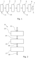
- the scene classification system shown in Figure 1 is based on an object detection architecture used to provide object detection and scene classification using radar-only data for an ego vehicle, namely the vehicle within which the radar system is incorporated. As such, the system is able to categorically classify the environment the subject vehicle is in based on the input radar data.
- the object detection architecture is object detection and semantic segmentation system employing a RaDOR-Net (Radar Deep Object Recognition network) architecture.
- RaDOR-Net is a deep-learning, end-to-end architecture for processing raw CDC (Compressed Data Cube) radar signals to provide semantic object and scene information, such as bounding boxes, free-space and semantic segmentation.
- the raw radar sensor data 11 from the vehicle's radar sensor system is input and processed through a number of processing layers.
- the processing layers include the CDC Domain SubNet 1, a POLAR Domain SubNet 2, a vehicle coordinate system (VCS) Sensor Domain 3, a VCS Fused Domain SubNet 4, a Gated Recurrent Unit (GRU) 5, and a dilated pyramid convolution layer 6.
- Looktype (scan type), Ego-motion, and Extrinsic Calibration data 11 may be fed into the Polar Domain SubNet 11, and Ego-motion data 10 may be fed into the GRU 5.
- the output from the Dilated Pyramid 6 is fed to a box head 7. At the same time, the output is fed to the scene classification head 8 for classification operations, as described in further detail below.
- the scene classification head 8 is connected after the dilated pyramid convolution layer 6, and is used as a feature extractor.
- the input information accesses the full activation after the GRU 5 and processes this information in a cascade of layers into the final scene classification scores.
- multiple classifications can be correct at the same time. For example, a rainy scene and approaching a tunnel scene may both be present.
- the final class activation is transformed using a sigmoid activation function, together with a cross-entropy loss operation for optimization.
- Sigmoid activation is used to create probabilities for each output. Accordingly, the output scene classification scores provide an indication for each scene category of the probability that a scene is being detected.
- the scene classification head 8 allows the scene classification head 8 to be incorporated into existing neural networks. That is, because the branch from the network occurs at the end, the calculations applied to the original output of an existing network remain unchanged. Accordingly, trained existing networks can be used, and their capabilities can simply be extended by the scene classification output, without affecting with the original performance.
- the scene classification head works with highly semantic features, already trained on a large dataset. Consequently, less parameters are required for the new scene classification output. This not only reduces computational complexity, but also reduces the number of samples which are required for the model to generalize well.
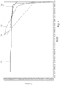
- An illustrative scene classification head 8 is shown in Figure 2 .
- the output from the dilated pyramid convolution layer 6 is fed to the input 12.
- An encoding and pooling module 13 processes the input data, firstly by using 2D-convolutions to encode local features.
- the aggregated feature data is then processed using a longitudinal and lateral feature pooling technique, as is discussed in further detail below.
- the feature pooling output 14 is then fed to an inner product module 15 to produce a low dimensional, inner product output 16.
- a final feature vector is generated for scene classification.
- the inner product output 16 is then fed to a classifier module 17 which classifies the scene and outputs one or more scene classification scores 18.
- Figure 3 shows a flow diagram of the processing steps employed in the scene classification architecture.
- the scene classification head 8 utilizes stacked lateral and longitudinal feature pooling, concatenation, and inner product calculations. For simplicity, only a single channel of the multi-channel activations is shown in Figure 3 .
- the raw CDC radar data is processed through a plurality of convolutional layers within the object detection architecture shown in figure 1 .
- these are represented by convolutional layers 21 and 22.
- the output of the object detection architecture produces feature or activation maps in which aggregated features result in highly activated areas within the channel matrices.
- the feature maps output by the convolutional layers 21 and 22 follow a vehicle-centric coordinate system.
- This coordinate system defines the longitudinal and lateral axes along the column and row directions of the feature maps.
- the ego vehicle's driving direction is along the x axis of this coordinate system.
- the feature maps are subjected to longitudinal feature pooling 23 and lateral feature pooling 26 within the encoding and pooling module 13. These pooling operations are used to reduce the dimensions of the feature maps by summarising the features present in the longitudinal columns and lateral rows of the feature maps generated by the convolution layers 21,22.
- Maximum or mean feature pooling may be used. In maximum feature pooling, the maximum element is taken from each column or row of the feature map. As such, the output after maximum pooling is a feature map containing the most prominent features of each column or row of the previous feature map. In mean feature pooling, the mean average of the elements present in each column or row of the feature map is taken. As such, the output after mean-pooling is a feature map containing the average features for each column or row of the previous feature map.
- the lateral and longitudinal feature pooling results are then concatenated and an inner product calculation 24 is produced.
- the lateral feature pooling 26 will result in stable features during the approach.
- the longitudinal feature pooling 23 will be distance dependent. For instance, if a tunnel is a distance away (e.g. 80m), the features of the tunnel will propagate along the vector as the car approaches. As such, it is possible to efficiently encode distance to scene transitions, for example, approaching tunnel in 40m. Accordingly, scenes of different types will result in different combination of the lateral and longitudinal feature pooling results. By concatenating these, and calculating their inner products, one or more scene classification scores can thereby be produced to provide a probability value indicating the probability that vehicle is in the associated scene category.
- a probability threshold may be set by which scene classification scores above a specified level are used to confirm the identification of a particular scene.
- Figure 4 is a graph comparing the scene classification performance of the illustrative embodiment with a conventional convolutional neural network and max pooling scene classification system.
- the recall-precision performance when the ego vehicle is in a parking garage scene is identified by line 31 for the illustrative embodiment, and contrasted with line 32 associated with a conventional classification system.
- the recall-precision performance when the ego vehicle is in a tunnel scene is identified by line 33 for the illustrative embodiment, and contrasted with line 34 associated with a conventional classification system.
- line 31 for the illustrative embodiment
- line 32 associated with a conventional classification system.
- the recall-precision performance when the ego vehicle is in a tunnel scene is identified by line 33 for the illustrative embodiment, and contrasted with line 34 associated with a conventional classification system.
- line 34 associated with a conventional classification system.
- the scene classification head is implemented using a plurality of modules, it will be understood that this, as well as the object detection architecture generally may be implemented using one or more microprocessors, for instance as part of an embedded device or an automotive controller unit.
- a vehicle advanced driver assist system can operate the scene classification method as described above and adapt one of more functions of the system according to the classification from the method.
- the system can use the classification from the method for blind spot information, lane departure warning, braking, speed adjustment, parking and so on.
Landscapes
- Engineering & Computer Science (AREA)
- Physics & Mathematics (AREA)
- Theoretical Computer Science (AREA)
- General Physics & Mathematics (AREA)
- Evolutionary Computation (AREA)
- Remote Sensing (AREA)
- Radar, Positioning & Navigation (AREA)
- Multimedia (AREA)
- Artificial Intelligence (AREA)
- Software Systems (AREA)
- Health & Medical Sciences (AREA)
- General Health & Medical Sciences (AREA)
- Computing Systems (AREA)
- Computer Networks & Wireless Communication (AREA)
- Databases & Information Systems (AREA)
- Computer Vision & Pattern Recognition (AREA)
- Medical Informatics (AREA)
- Computational Linguistics (AREA)
- Life Sciences & Earth Sciences (AREA)
- Biomedical Technology (AREA)
- Biophysics (AREA)
- Electromagnetism (AREA)
- Data Mining & Analysis (AREA)
- Molecular Biology (AREA)
- General Engineering & Computer Science (AREA)
- Mathematical Physics (AREA)
- Traffic Control Systems (AREA)
- Radar Systems Or Details Thereof (AREA)
- Image Analysis (AREA)
Abstract
Description
- The present disclosure relates to a scene classification method, apparatus, and computer program product. The disclosure is particularly relevant to radar-centric environment perception systems and methods, and most particularly for detecting the scene in which an ego vehicle is currently driving using radar-only data.
- The applicant is a pioneer in the field of radar-centric environment perception in automotive vehicles. Usually this task is tackled either by using traditional detection-based methods combined with a tracker, or by utilizing machine learning to predict object locations, estimating free-space and/or tracking objects. The environment in which the vehicle is operating has a significant bearing on the performance, such as the detection rate or false positive rate, of those algorithms. Scenes, such as parking garages or tunnels for instance, which have many reflecting surfaces in the proximity of the vehicle, significantly affect the performance of both traditional and machine-learning algorithms for radar-based perception. Furthermore, different algorithms and models may provide better performance in some scenes, and not others. As such, accurately detecting the scene the vehicle is currently in may allow system parameters, such as settings and behaviours, to be adjusted accordingly, for example by adaptive fusion, for thereby providing improved driver assistance systems in cars and other vehicles.
- Accordingly, there remains a need for improved systems for identifying the environment a vehicle is in.
- According to a first aspect, there is provided a scene classification method for a vehicle sensor system, the method including the steps of: receiving feature maps generated from sensor data provided by the vehicle sensor system; processing the feature maps using longitudinal and lateral feature pooling to generate longitudinal and lateral feature pool outputs; generating inner products from the longitudinal and lateral feature pool outputs; and classifying the scene based on the generated inner products.
- In this way, a computationally efficient classification method may be provided, which is able to outperform conventional classification architectures in terms of precision and recall performance. That is, by feature pooling the rows and columns of the feature maps, a low dimensional output may be generated, providing for efficient processing. At the same time the longitudinal and lateral pooling architecture leverages an awareness of scene features associated with particular environments to provide a high specificity for scene classification.
- In embodiments, the step of generating the inner product includes concatenating the longitudinal and lateral feature pool outputs. In this way, the longitudinal and lateral feature pool outputs for each channel output by the convolutional layers may be linked for subsequent inner product processing.
- In embodiments, the longitudinal and lateral feature pooling includes one of maximum or mean feature pooling. In this way, the size of the feature map may be reduced prior to subsequent inner product calculations.
- In embodiments, the step of classifying the scene includes generating one or more scene classification scores using the generated inner products. In this way, scenes detected by the sensor system may be classified into one or more different scene categories. These results may then be used to provide scene category information for optimising other processes and systems within the vehicle.
- In embodiments, the one or more scene classification scores provide a probability value indicating the probability that the associated scene is detected. In this way, the parameters used during the implementation of other processes and systems within the vehicle may be adjusted based on the probability results.
- In embodiments, the vehicle sensor system is a RADAR or LIDAR system. In this way, scene classification data may be derived using only RADAR or LIDAR sensor systems.
- In embodiments, the feature maps represent vehicle-centric coordinate system, and the direction of the rows and columns of the feature maps are parallel with the respective longitudinal and lateral axes of the coordinate system. In this way, awareness of the driving direction is leveraged to produce highly specific longitudinal and lateral feature pool outputs.
- In embodiments, the classification method further includes the step of generating feature maps from the sensor data provided by the vehicle sensor system, wherein the step of generating the feature maps includes processing the sensor data through an object detection system. In this way, the classification method may be implemented as a head on an intermediate sematic representation for the object detection system, thereby capitalising on existing processing operations whilst providing additional classification functionality.
- In embodiments, the object detection system includes an artificial neural network architecture. In this way, the classification head may be added to provide additional functionality to an existing trained model.
- In embodiments, the artificial neural network architecture is a Radar Deep Object Recognition network, RaDOR.net.
- According to a further aspect, there is provided a computer program product including instructions which, when the program is executed by a computer, cause the computer to carry out the steps of the above method.
- According to a further aspect, there is provided a non-transitory computer readable medium including instructions, which when executed by a processor, cause the processor to execute the above method.
- According to a further aspect, there is provided a scene classification apparatus for processing data from a vehicle sensor system, the apparatus including: an input for receiving feature maps generated from sensor data provided by the vehicle sensor system; and an encoding and pooling module for processing the feature maps using longitudinal and lateral feature pooling to generate longitudinal and lateral feature pool outputs; an inner product module for generating inner products from the longitudinal and lateral feature pool outputs; and a classifier for classifying the scene based on the generated inner products. In this way, an apparatus may be provided for implementing the above method.
- In embodiments, the inner product module is configured to concatenate the longitudinal and lateral feature pool outputs.
- In embodiments, the encoding and pooling module is configured to perform one of maximum or mean feature pooling.
- In embodiments, the classifier is configured to generate one or more scene classification scores using the generated inner products.
- In embodiments, the one or more scene classification scores provide a probability value indicating the probability that the associated scene is detected.
- In embodiments, the vehicle sensor system is a RADAR or LIDAR system.
- In embodiments, the feature maps represent a vehicle-centric coordinate system, and the direction of the rows and columns of the feature maps are parallel with the respective longitudinal and lateral axes of the coordinate system.
- In embodiments, the scene classification apparatus further includes an object detection system for processing sensor data received from the vehicle sensor system to generate the feature maps.
- In embodiments, the object detection system includes an artificial neural network architecture.
- In embodiments, the artificial neural network architecture is a Radar Deep Object Recognition network, RaDOR.net.
- Illustrative embodiments will now be described with reference to the accompanying drawings in which:
-
Figure 1 shows a schematic illustration of a scene classification system based on an object detection architecture according to an embodiment; -
Figure 2 shows a schematic illustration of the scene classification head according to an embodiment; -
Figure 3 is a flow diagram of the processing steps employed in the scene classification system shown inFigure 2 ; and -
Figure 4 is a graph comparing the scene classification performance of the illustrative embodiment with a conventional convolutional neural network and max pooling scene classification system. - The scene classification system shown in
Figure 1 is based on an object detection architecture used to provide object detection and scene classification using radar-only data for an ego vehicle, namely the vehicle within which the radar system is incorporated. As such, the system is able to categorically classify the environment the subject vehicle is in based on the input radar data. - In this embodiment, the object detection architecture is object detection and semantic segmentation system employing a RaDOR-Net (Radar Deep Object Recognition network) architecture. RaDOR-Net is a deep-learning, end-to-end architecture for processing raw CDC (Compressed Data Cube) radar signals to provide semantic object and scene information, such as bounding boxes, free-space and semantic segmentation. The raw
radar sensor data 11 from the vehicle's radar sensor system is input and processed through a number of processing layers. In this example, the processing layers include the CDC Domain SubNet 1, a POLAR Domain SubNet 2, a vehicle coordinate system (VCS)Sensor Domain 3, a VCS Fused Domain SubNet 4, a Gated Recurrent Unit (GRU) 5, and a dilatedpyramid convolution layer 6. Looktype (scan type), Ego-motion, andExtrinsic Calibration data 11 may be fed into the Polar Domain SubNet 11, and Ego-motion data 10 may be fed into theGRU 5. The output from the Dilated Pyramid 6 is fed to abox head 7. At the same time, the output is fed to thescene classification head 8 for classification operations, as described in further detail below. - The
scene classification head 8 is connected after the dilatedpyramid convolution layer 6, and is used as a feature extractor. The input information accesses the full activation after theGRU 5 and processes this information in a cascade of layers into the final scene classification scores. In this respect, it will be understood that multiple classifications can be correct at the same time. For example, a rainy scene and approaching a tunnel scene may both be present. As such, the final class activation is transformed using a sigmoid activation function, together with a cross-entropy loss operation for optimization. Sigmoid activation is used to create probabilities for each output. Accordingly, the output scene classification scores provide an indication for each scene category of the probability that a scene is being detected. - With the arrangement described, by branching the
scene classification head 8 after the dilatedpyramid layer 6, several advantages may be achieved. Firstly, computational complexity is minimized because most calculations performed in the network for bounding box classification are also used for thescene classification head 8. This thereby significantly reduces the complexity at inference and training time compared to an architecture with earlier branching. - Secondly, it allows the
scene classification head 8 to be incorporated into existing neural networks. That is, because the branch from the network occurs at the end, the calculations applied to the original output of an existing network remain unchanged. Accordingly, trained existing networks can be used, and their capabilities can simply be extended by the scene classification output, without affecting with the original performance. - Thirdly, data utilization is also improved. The scene classification head works with highly semantic features, already trained on a large dataset. Consequently, less parameters are required for the new scene classification output. This not only reduces computational complexity, but also reduces the number of samples which are required for the model to generalize well.
- An illustrative
scene classification head 8 is shown inFigure 2 . The output from the dilatedpyramid convolution layer 6 is fed to theinput 12. An encoding and poolingmodule 13 processes the input data, firstly by using 2D-convolutions to encode local features. The aggregated feature data, is then processed using a longitudinal and lateral feature pooling technique, as is discussed in further detail below. Thefeature pooling output 14 is then fed to aninner product module 15 to produce a low dimensional,inner product output 16. As such, a final feature vector is generated for scene classification. Accordingly, theinner product output 16 is then fed to aclassifier module 17 which classifies the scene and outputs one or more scene classification scores 18. - To explain the scene classification method in further detail,
Figure 3 shows a flow diagram of the processing steps employed in the scene classification architecture. As mentioned above, thescene classification head 8 utilizes stacked lateral and longitudinal feature pooling, concatenation, and inner product calculations. For simplicity, only a single channel of the multi-channel activations is shown inFigure 3 . - As will be understood, the raw CDC radar data is processed through a plurality of convolutional layers within the object detection architecture shown in
figure 1 . InFigure 3 , for simplicity, these are represented byconvolutional layers - As will be understood, the feature maps output by the
convolutional layers - The feature maps are subjected to longitudinal feature pooling 23 and lateral feature pooling 26 within the encoding and pooling
module 13. These pooling operations are used to reduce the dimensions of the feature maps by summarising the features present in the longitudinal columns and lateral rows of the feature maps generated by the convolution layers 21,22. Maximum or mean feature pooling may be used. In maximum feature pooling, the maximum element is taken from each column or row of the feature map. As such, the output after maximum pooling is a feature map containing the most prominent features of each column or row of the previous feature map. In mean feature pooling, the mean average of the elements present in each column or row of the feature map is taken. As such, the output after mean-pooling is a feature map containing the average features for each column or row of the previous feature map. - The lateral and longitudinal feature pooling results are then concatenated and an
inner product calculation 24 is produced. - In a scenario where the car approaches a tunnel, the lateral feature pooling 26 will result in stable features during the approach. In contrast, the longitudinal feature pooling 23 will be distance dependent. For instance, if a tunnel is a distance away (e.g. 80m), the features of the tunnel will propagate along the vector as the car approaches. As such, it is possible to efficiently encode distance to scene transitions, for example, approaching tunnel in 40m. Accordingly, scenes of different types will result in different combination of the lateral and longitudinal feature pooling results. By concatenating these, and calculating their inner products, one or more scene classification scores can thereby be produced to provide a probability value indicating the probability that vehicle is in the associated scene category. A probability threshold may be set by which scene classification scores above a specified level are used to confirm the identification of a particular scene.
-
Figure 4 is a graph comparing the scene classification performance of the illustrative embodiment with a conventional convolutional neural network and max pooling scene classification system. The recall-precision performance when the ego vehicle is in a parking garage scene is identified byline 31 for the illustrative embodiment, and contrasted withline 32 associated with a conventional classification system. Equally, the recall-precision performance when the ego vehicle is in a tunnel scene is identified byline 33 for the illustrative embodiment, and contrasted withline 34 associated with a conventional classification system. As shown, in both cases, higher recall and precision values are achieved with the illustrative embodiment. - Accordingly, the above methods and systems allow for highly accurate and computationally efficient scene classification.
- It will be understood that the embodiments illustrated above show applications only for the purposes of illustration. In practice, embodiments may be applied to many different configurations, the detailed embodiments being straightforward for those skilled in the art to implement.
- For example, although in the above illustrative examples, the scene classification head is implemented using a plurality of modules, it will be understood that this, as well as the object detection architecture generally may be implemented using one or more microprocessors, for instance as part of an embedded device or an automotive controller unit.
- It will be appreciated that a vehicle advanced driver assist system can operate the scene classification method as described above and adapt one of more functions of the system according to the classification from the method. In particular, as a non-exclusive list, the system can use the classification from the method for blind spot information, lane departure warning, braking, speed adjustment, parking and so on.
Claims (15)
- A scene classification method for a vehicle sensor system, the method comprising the steps of:receiving feature maps generated from sensor data provided by the vehicle sensor system; andprocessing the feature maps using longitudinal and lateral feature pooling to generate longitudinal and lateral feature pool outputs;generating inner products from the longitudinal and lateral feature pool outputs; andclassifying the scene based on the generated inner products.
- A scene classification method according to claim 1, wherein the step of generating the inner product comprises concatenating the longitudinal and lateral feature pool outputs.
- A scene classification method according to claim 1 or 2, wherein longitudinal and lateral feature pooling comprises one of maximum or mean feature pooling.
- A scene classification method according to any preceding claim, wherein the step of classifying the scene comprises generating one or more scene classification scores using the generated inner products.
- A scene classification method according to claim 4, wherein the one or more scene classification scores provide a probability value indicating the probability that the associated scene is detected.
- A scene classification method according to any preceding claim, wherein the feature maps represent a vehicle-centric coordinate system, and the direction of the rows and columns of the feature maps are parallel with the respective longitudinal and lateral axes of the coordinate system.
- A scene classification method according to any preceding claim, further comprising the step of generating feature maps from the sensor data provided by the vehicle sensor system, wherein the step of generating the feature maps comprises processing the sensor data through an object detection system.
- A scene classification method according to claim 7, wherein the object detection system comprises an artificial neural network architecture.
- A non-transitory computer readable medium comprising instructions, which when executed by a processor, cause the processor to execute the method according to any one of claims 1-8.
- A scene classification apparatus for processing data from a vehicle sensor system, the apparatus comprising:an input for receiving feature maps generated from sensor data provided by the vehicle sensor system; andan encoding and pooling module for processing the feature maps using longitudinal and lateral feature pooling to generate longitudinal and lateral feature pool outputs;an inner product module for generating inner products from the longitudinal and lateral feature pool outputs; anda classifier for classifying the scene based on the generated inner products.
- A scene classification apparatus according to claim 10, wherein the inner product module is configured to concatenate the longitudinal and lateral feature pool outputs.
- A scene classification apparatus according to any of claims 10 or 11, wherein the classifier is configured to generate one or more scene classification scores using the generated inner products.
- A scene classification apparatus according to claim 12, wherein the one or more scene classification scores provide a probability value indicating the probability that the associated scene is detected.
- A scene classification apparatus according to any preceding claim, further comprising an object detection system for processing sensor data received from the vehicle sensor system to generate the feature maps.
- A vehicle advanced driver assist system operating the scene classification method according to any one of claims 1 to 8 and adapting one of more functions of the system according to the classification from the method.
Applications Claiming Priority (1)
| Application Number | Priority Date | Filing Date | Title |
|---|---|---|---|
| GBGB2205533.9A GB202205533D0 (en) | 2022-04-14 | 2022-04-14 | Scene classification method, apparatus and computer program product |
Publications (2)
| Publication Number | Publication Date |
|---|---|
| EP4258009A1 true EP4258009A1 (en) | 2023-10-11 |
| EP4258009B1 EP4258009B1 (en) | 2025-09-03 |
Family
ID=81753184
Family Applications (1)
| Application Number | Title | Priority Date | Filing Date |
|---|---|---|---|
| EP23153861.2A Active EP4258009B1 (en) | 2022-04-14 | 2023-01-30 | Scene classification method, apparatus and computer program product |
Country Status (4)
| Country | Link |
|---|---|
| US (1) | US20230334870A1 (en) |
| EP (1) | EP4258009B1 (en) |
| CN (1) | CN116912800B (en) |
| GB (1) | GB202205533D0 (en) |
Citations (1)
| Publication number | Priority date | Publication date | Assignee | Title |
|---|---|---|---|---|
| WO2018158293A1 (en) * | 2017-02-28 | 2018-09-07 | Frobas Gmbh | Allocation of computational units in object classification |
Family Cites Families (3)
| Publication number | Priority date | Publication date | Assignee | Title |
|---|---|---|---|---|
| CN110222182B (en) * | 2019-06-06 | 2022-12-27 | 腾讯科技(深圳)有限公司 | Statement classification method and related equipment |
| EP3943968A1 (en) * | 2020-07-24 | 2022-01-26 | Aptiv Technologies Limited | Methods and system for detection of objects in a vicinity of a vehicle |
| CN112581498B (en) * | 2020-11-17 | 2024-03-29 | 东南大学 | Road side shielding scene vehicle robust tracking method for intelligent vehicle road system |
-
2022
- 2022-04-14 GB GBGB2205533.9A patent/GB202205533D0/en not_active Ceased
-
2023
- 2023-01-30 EP EP23153861.2A patent/EP4258009B1/en active Active
- 2023-03-15 US US18/184,294 patent/US20230334870A1/en active Pending
- 2023-04-03 CN CN202310348212.8A patent/CN116912800B/en active Active
Patent Citations (1)
| Publication number | Priority date | Publication date | Assignee | Title |
|---|---|---|---|---|
| WO2018158293A1 (en) * | 2017-02-28 | 2018-09-07 | Frobas Gmbh | Allocation of computational units in object classification |
Non-Patent Citations (1)
| Title |
|---|
| YOU-CHEN LIN ET AL: "Using Deep Learning and Gaussian Mixture Models for Road Scene Segmentation", INTERNATIONAL JOURNAL OF ENGINEERING SCIENCE AND INNOVATIVE TECHNOLOGY, 1 November 2017 (2017-11-01), pages 27, XP055770726, Retrieved from the Internet <URL:https://www.ijesit.com/Volume%206/Issue%206/IJESIT201706_04.pdf> [retrieved on 20210201] * |
Also Published As
| Publication number | Publication date |
|---|---|
| CN116912800A (en) | 2023-10-20 |
| GB202205533D0 (en) | 2022-06-01 |
| EP4258009B1 (en) | 2025-09-03 |
| US20230334870A1 (en) | 2023-10-19 |
| CN116912800B (en) | 2025-11-18 |
Similar Documents
| Publication | Publication Date | Title |
|---|---|---|
| US12333784B2 (en) | Trajectory prediction method and device | |
| CN105892471B (en) | Automatic driving method and apparatus | |
| US11453335B2 (en) | Intelligent ultrasonic system and rear collision warning apparatus for vehicle | |
| US11327178B2 (en) | Piece-wise network structure for long range environment perception | |
| CN114043989B (en) | Driving style recognition model, lane change decision model and decision method based on recursion diagram and convolutional neural network | |
| CN113611008B (en) | Vehicle driving scene acquisition method, device, equipment and medium | |
| CN109633621A (en) | A kind of vehicle environment sensory perceptual system data processing method | |
| US12607719B2 (en) | Method for detecting at least one object in surroundings by means of reflection signals of a radar sensor system | |
| CN113837222A (en) | Cloud-edge cooperative machine learning deployment application method and device for millimeter wave radar intersection traffic monitoring system | |
| CN111114541B (en) | Vehicle control method, device, controller and smart car | |
| US12545295B2 (en) | Image-based generation of descriptive and perceptive messages of automotive scenes | |
| Bouain et al. | Multi-sensor fusion for obstacle detection and recognition: A belief-based approach | |
| EP4258009B1 (en) | Scene classification method, apparatus and computer program product | |
| Zhang et al. | Steering angle prediction for autonomous cars based on deep neural network method | |
| CN109709541A (en) | A kind of vehicle environment perception emerging system target erroneous detection processing method | |
| Roomi et al. | Hand gesture recognition system using transfer learning | |
| EP4553788A1 (en) | Object detection using a trained neural network | |
| CN118552934A (en) | Object detection method, device, electronic apparatus, vehicle, medium, and program product | |
| GB2593482A (en) | A method for associating a traffic light detection for an at least partially autonomous motor vehicle, as well as an assistance system | |
| TWI901538B (en) | Data alignment method and intelligent vehicle | |
| KR20230011774A (en) | Method and system for data recording of vehicle | |
| Ghani et al. | Radar based pedestrian classification using deep learning approach | |
| US20260105758A1 (en) | Leveraging llms for video analysis | |
| CN119693923B (en) | Path planning method combining small-scale traffic sign recognition and DWA algorithm | |
| EP4651097A1 (en) | Method for determining semantic image data based on spatial context de-scriptors |
Legal Events
| Date | Code | Title | Description |
|---|---|---|---|
| PUAI | Public reference made under article 153(3) epc to a published international application that has entered the european phase |
Free format text: ORIGINAL CODE: 0009012 |
|
| STAA | Information on the status of an ep patent application or granted ep patent |
Free format text: STATUS: THE APPLICATION HAS BEEN PUBLISHED |
|
| AK | Designated contracting states |
Kind code of ref document: A1 Designated state(s): AL AT BE BG CH CY CZ DE DK EE ES FI FR GB GR HR HU IE IS IT LI LT LU LV MC ME MK MT NL NO PL PT RO RS SE SI SK SM TR |
|
| STAA | Information on the status of an ep patent application or granted ep patent |
Free format text: STATUS: REQUEST FOR EXAMINATION WAS MADE |
|
| 17P | Request for examination filed |
Effective date: 20240306 |
|
| RBV | Designated contracting states (corrected) |
Designated state(s): AL AT BE BG CH CY CZ DE DK EE ES FI FR GB GR HR HU IE IS IT LI LT LU LV MC ME MK MT NL NO PL PT RO RS SE SI SK SM TR |
|
| RAP1 | Party data changed (applicant data changed or rights of an application transferred) |
Owner name: APTIV TECHNOLOGIES AG |
|
| RAP3 | Party data changed (applicant data changed or rights of an application transferred) |
Owner name: APTIV TECHNOLOGIES AG |
|
| REG | Reference to a national code |
Ref country code: DE Ref legal event code: R079 Free format text: PREVIOUS MAIN CLASS: G01S0007295000 Ipc: G01S0007410000 Ref document number: 602023006195 Country of ref document: DE |
|
| GRAP | Despatch of communication of intention to grant a patent |
Free format text: ORIGINAL CODE: EPIDOSNIGR1 |
|
| STAA | Information on the status of an ep patent application or granted ep patent |
Free format text: STATUS: GRANT OF PATENT IS INTENDED |
|
| RIC1 | Information provided on ipc code assigned before grant |
Ipc: G06V 10/82 20220101ALI20250506BHEP Ipc: G06V 10/44 20220101ALI20250506BHEP Ipc: G01S 7/295 20060101ALI20250506BHEP Ipc: G01S 17/931 20200101ALI20250506BHEP Ipc: G01S 13/931 20200101ALI20250506BHEP Ipc: G01S 7/48 20060101ALI20250506BHEP Ipc: G01S 7/41 20060101AFI20250506BHEP |
|
| INTG | Intention to grant announced |
Effective date: 20250516 |
|
| GRAS | Grant fee paid |
Free format text: ORIGINAL CODE: EPIDOSNIGR3 |
|
| GRAA | (expected) grant |
Free format text: ORIGINAL CODE: 0009210 |
|
| STAA | Information on the status of an ep patent application or granted ep patent |
Free format text: STATUS: THE PATENT HAS BEEN GRANTED |
|
| AK | Designated contracting states |
Kind code of ref document: B1 Designated state(s): AL AT BE BG CH CY CZ DE DK EE ES FI FR GB GR HR HU IE IS IT LI LT LU LV MC ME MK MT NL NO PL PT RO RS SE SI SK SM TR |
|
| REG | Reference to a national code |
Ref country code: CH Ref legal event code: EP |
|
| P01 | Opt-out of the competence of the unified patent court (upc) registered |
Free format text: CASE NUMBER: UPC_APP_3821_4258009/2025 Effective date: 20250820 |
|
| REG | Reference to a national code |
Ref country code: DE Ref legal event code: R096 Ref document number: 602023006195 Country of ref document: DE |
|
| REG | Reference to a national code |
Ref country code: IE Ref legal event code: FG4D |
|
| REG | Reference to a national code |
Ref country code: NL Ref legal event code: MP Effective date: 20250903 |
|
| PG25 | Lapsed in a contracting state [announced via postgrant information from national office to epo] |
Ref country code: NO Free format text: LAPSE BECAUSE OF FAILURE TO SUBMIT A TRANSLATION OF THE DESCRIPTION OR TO PAY THE FEE WITHIN THE PRESCRIBED TIME-LIMIT Effective date: 20251203 |
|
| REG | Reference to a national code |
Ref country code: LT Ref legal event code: MG9D |
|
| PG25 | Lapsed in a contracting state [announced via postgrant information from national office to epo] |
Ref country code: FI Free format text: LAPSE BECAUSE OF FAILURE TO SUBMIT A TRANSLATION OF THE DESCRIPTION OR TO PAY THE FEE WITHIN THE PRESCRIBED TIME-LIMIT Effective date: 20250903 |
|
| PG25 | Lapsed in a contracting state [announced via postgrant information from national office to epo] |
Ref country code: HR Free format text: LAPSE BECAUSE OF FAILURE TO SUBMIT A TRANSLATION OF THE DESCRIPTION OR TO PAY THE FEE WITHIN THE PRESCRIBED TIME-LIMIT Effective date: 20250903 |
|
| PG25 | Lapsed in a contracting state [announced via postgrant information from national office to epo] |
Ref country code: GR Free format text: LAPSE BECAUSE OF FAILURE TO SUBMIT A TRANSLATION OF THE DESCRIPTION OR TO PAY THE FEE WITHIN THE PRESCRIBED TIME-LIMIT Effective date: 20251204 |
|
| PG25 | Lapsed in a contracting state [announced via postgrant information from national office to epo] |
Ref country code: SE Free format text: LAPSE BECAUSE OF FAILURE TO SUBMIT A TRANSLATION OF THE DESCRIPTION OR TO PAY THE FEE WITHIN THE PRESCRIBED TIME-LIMIT Effective date: 20250903 |
|
| PG25 | Lapsed in a contracting state [announced via postgrant information from national office to epo] |
Ref country code: LV Free format text: LAPSE BECAUSE OF FAILURE TO SUBMIT A TRANSLATION OF THE DESCRIPTION OR TO PAY THE FEE WITHIN THE PRESCRIBED TIME-LIMIT Effective date: 20250903 |
|
| PG25 | Lapsed in a contracting state [announced via postgrant information from national office to epo] |
Ref country code: BG Free format text: LAPSE BECAUSE OF FAILURE TO SUBMIT A TRANSLATION OF THE DESCRIPTION OR TO PAY THE FEE WITHIN THE PRESCRIBED TIME-LIMIT Effective date: 20250903 Ref country code: PL Free format text: LAPSE BECAUSE OF FAILURE TO SUBMIT A TRANSLATION OF THE DESCRIPTION OR TO PAY THE FEE WITHIN THE PRESCRIBED TIME-LIMIT Effective date: 20250903 |
|
| PG25 | Lapsed in a contracting state [announced via postgrant information from national office to epo] |
Ref country code: RS Free format text: LAPSE BECAUSE OF FAILURE TO SUBMIT A TRANSLATION OF THE DESCRIPTION OR TO PAY THE FEE WITHIN THE PRESCRIBED TIME-LIMIT Effective date: 20251203 |
|
| PG25 | Lapsed in a contracting state [announced via postgrant information from national office to epo] |
Ref country code: ES Free format text: LAPSE BECAUSE OF FAILURE TO SUBMIT A TRANSLATION OF THE DESCRIPTION OR TO PAY THE FEE WITHIN THE PRESCRIBED TIME-LIMIT Effective date: 20250903 |
|
| REG | Reference to a national code |
Ref country code: AT Ref legal event code: MK05 Ref document number: 1833661 Country of ref document: AT Kind code of ref document: T Effective date: 20250903 |
|
| PG25 | Lapsed in a contracting state [announced via postgrant information from national office to epo] |
Ref country code: NL Free format text: LAPSE BECAUSE OF FAILURE TO SUBMIT A TRANSLATION OF THE DESCRIPTION OR TO PAY THE FEE WITHIN THE PRESCRIBED TIME-LIMIT Effective date: 20250903 |
|
| PG25 | Lapsed in a contracting state [announced via postgrant information from national office to epo] |
Ref country code: SM Free format text: LAPSE BECAUSE OF FAILURE TO SUBMIT A TRANSLATION OF THE DESCRIPTION OR TO PAY THE FEE WITHIN THE PRESCRIBED TIME-LIMIT Effective date: 20250903 |
|
| PGFP | Annual fee paid to national office [announced via postgrant information from national office to epo] |
Ref country code: DE Payment date: 20251217 Year of fee payment: 4 |
|
| PG25 | Lapsed in a contracting state [announced via postgrant information from national office to epo] |
Ref country code: AT Free format text: LAPSE BECAUSE OF FAILURE TO SUBMIT A TRANSLATION OF THE DESCRIPTION OR TO PAY THE FEE WITHIN THE PRESCRIBED TIME-LIMIT Effective date: 20250903 |
|
| PG25 | Lapsed in a contracting state [announced via postgrant information from national office to epo] |
Ref country code: IT Free format text: LAPSE BECAUSE OF FAILURE TO SUBMIT A TRANSLATION OF THE DESCRIPTION OR TO PAY THE FEE WITHIN THE PRESCRIBED TIME-LIMIT Effective date: 20250903 |
|
| PG25 | Lapsed in a contracting state [announced via postgrant information from national office to epo] |
Ref country code: IS Free format text: LAPSE BECAUSE OF FAILURE TO SUBMIT A TRANSLATION OF THE DESCRIPTION OR TO PAY THE FEE WITHIN THE PRESCRIBED TIME-LIMIT Effective date: 20260103 |
|
| PGFP | Annual fee paid to national office [announced via postgrant information from national office to epo] |
Ref country code: FR Payment date: 20260107 Year of fee payment: 4 |
|
| PG25 | Lapsed in a contracting state [announced via postgrant information from national office to epo] |
Ref country code: CZ Free format text: LAPSE BECAUSE OF FAILURE TO SUBMIT A TRANSLATION OF THE DESCRIPTION OR TO PAY THE FEE WITHIN THE PRESCRIBED TIME-LIMIT Effective date: 20250903 Ref country code: PT Free format text: LAPSE BECAUSE OF FAILURE TO SUBMIT A TRANSLATION OF THE DESCRIPTION OR TO PAY THE FEE WITHIN THE PRESCRIBED TIME-LIMIT Effective date: 20260105 |
|
| PG25 | Lapsed in a contracting state [announced via postgrant information from national office to epo] |
Ref country code: EE Free format text: LAPSE BECAUSE OF FAILURE TO SUBMIT A TRANSLATION OF THE DESCRIPTION OR TO PAY THE FEE WITHIN THE PRESCRIBED TIME-LIMIT Effective date: 20250903 Ref country code: SK Free format text: LAPSE BECAUSE OF FAILURE TO SUBMIT A TRANSLATION OF THE DESCRIPTION OR TO PAY THE FEE WITHIN THE PRESCRIBED TIME-LIMIT Effective date: 20250903 |