EP4257947A1 - Vibration transducer with simplified calibration sensors for the monitoring of a static or vibrating structure - Google Patents
Vibration transducer with simplified calibration sensors for the monitoring of a static or vibrating structure Download PDFInfo
- Publication number
- EP4257947A1 EP4257947A1 EP23166435.0A EP23166435A EP4257947A1 EP 4257947 A1 EP4257947 A1 EP 4257947A1 EP 23166435 A EP23166435 A EP 23166435A EP 4257947 A1 EP4257947 A1 EP 4257947A1
- Authority
- EP
- European Patent Office
- Prior art keywords
- board
- sensor module
- transducer
- transducer according
- case
- Prior art date
- Legal status (The legal status is an assumption and is not a legal conclusion. Google has not performed a legal analysis and makes no representation as to the accuracy of the status listed.)
- Granted
Links
Images


Classifications
-
- G—PHYSICS
- G01—MEASURING; TESTING
- G01M—TESTING STATIC OR DYNAMIC BALANCE OF MACHINES OR STRUCTURES; TESTING OF STRUCTURES OR APPARATUS, NOT OTHERWISE PROVIDED FOR
- G01M7/00—Vibration-testing of structures; Shock-testing of structures
-
- G—PHYSICS
- G01—MEASURING; TESTING
- G01M—TESTING STATIC OR DYNAMIC BALANCE OF MACHINES OR STRUCTURES; TESTING OF STRUCTURES OR APPARATUS, NOT OTHERWISE PROVIDED FOR
- G01M5/00—Investigating the elasticity of structures, e.g. deflection of bridges or air-craft wings
- G01M5/0008—Investigating the elasticity of structures, e.g. deflection of bridges or air-craft wings of bridges
-
- G—PHYSICS
- G01—MEASURING; TESTING
- G01M—TESTING STATIC OR DYNAMIC BALANCE OF MACHINES OR STRUCTURES; TESTING OF STRUCTURES OR APPARATUS, NOT OTHERWISE PROVIDED FOR
- G01M5/00—Investigating the elasticity of structures, e.g. deflection of bridges or air-craft wings
- G01M5/0066—Investigating the elasticity of structures, e.g. deflection of bridges or air-craft wings by exciting or detecting vibration or acceleration
-
- G—PHYSICS
- G01—MEASURING; TESTING
- G01M—TESTING STATIC OR DYNAMIC BALANCE OF MACHINES OR STRUCTURES; TESTING OF STRUCTURES OR APPARATUS, NOT OTHERWISE PROVIDED FOR
- G01M5/00—Investigating the elasticity of structures, e.g. deflection of bridges or air-craft wings
- G01M5/0075—Investigating the elasticity of structures, e.g. deflection of bridges or air-craft wings by means of external apparatus, e.g. test benches or portable test systems
-
- H—ELECTRICITY
- H05—ELECTRIC TECHNIQUES NOT OTHERWISE PROVIDED FOR
- H05K—PRINTED CIRCUITS; CASINGS OR CONSTRUCTIONAL DETAILS OF ELECTRIC APPARATUS; MANUFACTURE OF ASSEMBLAGES OF ELECTRICAL COMPONENTS
- H05K7/00—Constructional details common to different types of electric apparatus
- H05K7/02—Arrangements of circuit components or wiring on supporting structure
- H05K7/10—Plug-in assemblages of components, e.g. IC sockets
- H05K7/1015—Plug-in assemblages of components, e.g. IC sockets having exterior leads
Definitions
- the present invention refers to a vibration transducer provided with simplified calibration sensors for the monitoring of a static or vibrating structure.
- Structural monitoring is a process by which the existing building is characterised and by which some properties of the structure are identified obtaining information to be able to assess possible changes in the structural behaviour, such as damage of the material or of the structural elements, modifications in the behaviour of constraints and connection systems, or other modifications which may cause changes in the structure performance.
- a structural monitoring system provides for the measurement of some quantities with time, using continuously a plurality of sensors (vibration, deformation, fissuring, corrosion, displacement, inclination, wind velocity, humidity and temperature sensors) placed in pre-established positions on the structure, in order to provide all the information needed to assess the structural behaviour of the structure under consideration.
- a structural monitoring system allows to carry out the monitoring even during the construction phase, ensuring higher safety and control of the constructions.
- the monitoring system allows the early detection of structural degradation compared with current checking methods, thus reducing high maintenance costs.
- the conventional sensors have the disadvantage that, if some calibrations or recalibrations have to be performed, there is the need to detach the electronic board with associated wiring from the case, and then remount a new electronic board, preserving the exact initial position of the sensor of the board with respect to the structure.
- the aim of the present invention is to design a vibration transducer, provided with at least one simplified calibration sensor for the monitoring of a static or vibrating structure, allowing to calibrate and/or replace in an easy and quick way the integrated sensors installed.
- an object of the invention is to provide a vibration transducer, equipped with at least one simplified calibration sensor for the monitoring of a static or vibrating structure, suitable to be calibrated even outside its installation site.
- a further object of the invention is to provide a vibration transducer, equipped with at least one simplified calibration sensor for the monitoring of a static or vibrating structure, which is suitable to simplify maintenance and recalibration interventions also after its installation, thus making up in a radical way for the degradation of its electric and mechanical parameters over time.
- a further object of the invention is to design a vibration transducer, equipped with at least one simplified calibration sensor for the monitoring of a static or vibrating structure, which ensures the stability of the coupling between the sensor module and the electronic board, even in presence of vibrations.
- a further object of the invention is to provide a vibration transducer, equipped with at least one simplified calibration sensor for the monitoring of a static or vibrating structure which, in addition to preventing complex in situ performance of calibrations or recalibrations, allows to detach the electronic board with the associated wiring and to reassemble the whole thing in the exact initial position of the sensor on the structure.
- the simplified calibration transducer for the monitoring of a static or vibrating structure of the invention is indicated as a whole with the numeral 1.
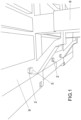
- the transducer 1 comprises a case 2 suitable to be applied to the structure 9 to be monitored (in the illustrated example the arches of a bridge).
- the transducer 1 also has an electronic board 3 attached within the case 2 and a sensor module 4 associable to the electronic board 3.
- the case 2 has also a closing lid 5 thereof.
- the sensor module 4 comprises first male coupling means 6 for coupling with second female coupling means 7 present on the board 3, to allow the manual attachment and detachment of the sensor module 4 itself from the electronic board 3, facilitating in this way the sensor calibration interventions.
- This solution allows to perform the calibrations or the recalibrations of the sensor 4, without the need to unmount the case 2 from its application site on the building to be monitored, or to detach from the case 2 the electronic board 3 with the associated wiring, and then being forced to reassemble the whole thing in the exact initial position of the sensor module 4 on the structure 9.
- the sensor part represented by the sensor module 4 is separated from the electronic board 3 and this allows to leave the electronic board 3 attached in the initial position thereof on the case 2, detaching only the sensor module 4 so that it can be replaced with a new sensor module calibrated in a correct way.
- the described operation also allows the advantage of preserving the pre-existing wiring between the transducer 1 and the associated monitoring system, which in fact do not need to be detached from the case body 2. This therefore allows to detach the sensor module 4 and to replace it with a previously calibrated one, or to position it back after the appropriate recalibration interventions, without having to remove the case or even the electronic board alone from the structure to be monitored.
- the aforementioned female coupling means consist of housings 7 placed within the socket 10.
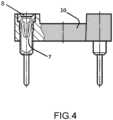
- FIG. 4 shows a sectional view of the socket 10 and the housing 7 for the respective male pin 6 of the sensor module 4.
- the socket 10 in figure is of the DIL (Dual In Line) type and such typology of sockets is provided with two parallel rows of housings 7 (in the present case two rows with twelve housings each).
- the housings 7 are of the turned type, having a conical inlet 8, which provides four points of contact with the male pins 6.
- the housings 7, with their four points of contact ensure a precise engagement and a stable contact over time with the male pins 6. The desired reliability of the electrical connection is therefore ensured, even in presence of vibrations on which the transducer of the invention is called to act.
- the coupling of the male pins 6 on the respective female housings 7 of the turned type provides stability to the assembling of the sensor module 4 on the electronic board 3, even in presence of vibrations on which the transducer of the invention is called to act.
- Figure 5 illustrates the insertion of the pins 6 of the sensor module 4 within the housings 7 of the DIL socket 10
- Figure 6 shows the sectional view of the coupling, that is achieved when the male pins 6 of the sensor module 4 engage within the corresponding housings 7 of the DIL socket 10.
- the plating of the housings 7, in addition, ensures optimal resistance to corrosion and oxidation.
- the transducer of the invention also has a safety element 11 for preventing the unintentional detaching of the module 4 from the board 3, which consists of a metal clamp having a shape combined with that of the module 4 and which is attached to the board 3 by suitable screws 13.
- the socket 10 is arranged in a position substantially central with respect to the board 3, so as to facilitate the manual operations of detachment and attachment to the board 3 itself and for an alignment with the cable glands 12.
- the module 4 alone is coated with a resin suitable to prevent any damage of the circuits aboard thereof, in particular a resin protective against atmospheric agents and electrostatic charges by direct contact.
- the resin coating the module 4 allows even to the user who is unskilled in electronics not to damage the circuits aboard the module itself.
- the male pins and female housings have a plating, suitable to ensure optimal resistance to corrosion and oxidation, while guaranteeing a precise engagement and a stable contact over time.
- Round contacts in addition, simplify the soldering on the PCB and improve the resistance thereof.
- the electronic board 3 may be left in position, together with the associated wiring within the case 2, extracting or removing the sensor module 4 alone to carry out its replacement.
- the invention allows the replacement of the sensor module 4 without any tool and following simple indications. This replacement as such provides a recalibration of the initial sensor.
Landscapes
- Physics & Mathematics (AREA)
- General Physics & Mathematics (AREA)
- Engineering & Computer Science (AREA)
- Aviation & Aerospace Engineering (AREA)
- Microelectronics & Electronic Packaging (AREA)
- Measurement Of Mechanical Vibrations Or Ultrasonic Waves (AREA)
- Measuring Fluid Pressure (AREA)
Abstract
Description
- The present invention refers to a vibration transducer provided with simplified calibration sensors for the monitoring of a static or vibrating structure.
- As is well known, the unavoidable deterioration of the physical and mechanical properties of materials, the obsolescence of the components, together with the usage of the existing building and the occurrence of natural events such as for example earthquakes, rains and landslides, require the research of monitoring systems allowing the state of health assessment of the structure and/or infrastructures under investigation, in order to carry out the necessary interventions for improving and/or restoring the safety conditions thereof and at the same time to reduce maintenance costs.
- Structural monitoring is a process by which the existing building is characterised and by which some properties of the structure are identified obtaining information to be able to assess possible changes in the structural behaviour, such as damage of the material or of the structural elements, modifications in the behaviour of constraints and connection systems, or other modifications which may cause changes in the structure performance.
- A structural monitoring system provides for the measurement of some quantities with time, using continuously a plurality of sensors (vibration, deformation, fissuring, corrosion, displacement, inclination, wind velocity, humidity and temperature sensors) placed in pre-established positions on the structure, in order to provide all the information needed to assess the structural behaviour of the structure under consideration.
- A structural monitoring system allows to carry out the monitoring even during the construction phase, ensuring higher safety and control of the constructions.
- Once completed the construction, in addition, the monitoring system allows the early detection of structural degradation compared with current checking methods, thus reducing high maintenance costs.
- Current sensors for the monitoring of a static or vibrating structure have however several drawbacks, among which a considerable criticality in maintenance necessary to keep them reliable in use, due to the degradation of electric and mechanical parameters with time. In fact, current sensors use an electronic board, with vibration detection function, integrally formed with the sensors, the processor, and other electronic components, for example soldered on the board body, the board being subsequently attached on the structure to be monitored.
- For this reason, the conventional sensors have the disadvantage that, if some calibrations or recalibrations have to be performed, there is the need to detach the electronic board with associated wiring from the case, and then remount a new electronic board, preserving the exact initial position of the sensor of the board with respect to the structure.
- The aim of the present invention is to design a vibration transducer, provided with at least one simplified calibration sensor for the monitoring of a static or vibrating structure, allowing to calibrate and/or replace in an easy and quick way the integrated sensors installed.
- Within this aim, an object of the invention is to provide a vibration transducer, equipped with at least one simplified calibration sensor for the monitoring of a static or vibrating structure, suitable to be calibrated even outside its installation site.
- A further object of the invention is to provide a vibration transducer, equipped with at least one simplified calibration sensor for the monitoring of a static or vibrating structure, which is suitable to simplify maintenance and recalibration interventions also after its installation, thus making up in a radical way for the degradation of its electric and mechanical parameters over time.
- A further object of the invention is to design a vibration transducer, equipped with at least one simplified calibration sensor for the monitoring of a static or vibrating structure, which ensures the stability of the coupling between the sensor module and the electronic board, even in presence of vibrations.
- A further object of the invention is to provide a vibration transducer, equipped with at least one simplified calibration sensor for the monitoring of a static or vibrating structure which, in addition to preventing complex in situ performance of calibrations or recalibrations, allows to detach the electronic board with the associated wiring and to reassemble the whole thing in the exact initial position of the sensor on the structure.
- This aim as well as these and other objects are achieved by the transducer of
claim 1. Preferred embodiments of the transducer of the invention result from the remaining claims. - These and other objects, advantages and features result from the following description of the transducer system of the invention illustrated, by way of non-limiting example, in the figures of the attached drawings.
- In these:
-
Figure 1 represents an example of application of the transducer of the invention to a structure to be monitored; -
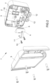
Figure 2 is a perspective view of the transducer of the invention, with the case in the open position, representative of the sensor module in a detached position from the electronic board; -
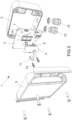
Figure 3 is an exploded perspective view of the transducer of the invention; -
Figure 4 illustrates, partially in section, the socket of the transducer of the invention; -
Figure 5 illustrates in an exploded view the mounting solution of the sensor module on the socket of the transducer of the invention; and -
Figure 6 illustrates, partially in section, the coupling of the sensor module on the socket of the preceding figures. - With particular reference to the above described figures, the simplified calibration transducer for the monitoring of a static or vibrating structure of the invention is indicated as a whole with the
numeral 1. - The
transducer 1 comprises acase 2 suitable to be applied to thestructure 9 to be monitored (in the illustrated example the arches of a bridge). Thetransducer 1 also has anelectronic board 3 attached within thecase 2 and asensor module 4 associable to theelectronic board 3. Thecase 2 has also aclosing lid 5 thereof. - Advantageously the
sensor module 4 comprises first male coupling means 6 for coupling with second female coupling means 7 present on theboard 3, to allow the manual attachment and detachment of thesensor module 4 itself from theelectronic board 3, facilitating in this way the sensor calibration interventions. - This solution allows to perform the calibrations or the recalibrations of the
sensor 4, without the need to unmount thecase 2 from its application site on the building to be monitored, or to detach from thecase 2 theelectronic board 3 with the associated wiring, and then being forced to reassemble the whole thing in the exact initial position of thesensor module 4 on thestructure 9. - In this way the sensor part represented by the
sensor module 4 is separated from theelectronic board 3 and this allows to leave theelectronic board 3 attached in the initial position thereof on thecase 2, detaching only thesensor module 4 so that it can be replaced with a new sensor module calibrated in a correct way. The described operation also allows the advantage of preserving the pre-existing wiring between thetransducer 1 and the associated monitoring system, which in fact do not need to be detached from thecase body 2. This therefore allows to detach thesensor module 4 and to replace it with a previously calibrated one, or to position it back after the appropriate recalibration interventions, without having to remove the case or even the electronic board alone from the structure to be monitored. - In particular, according to the invention, the aforementioned female coupling means consist of
housings 7 placed within thesocket 10. -
Figure 4 shows a sectional view of thesocket 10 and thehousing 7 for the respectivemale pin 6 of thesensor module 4. Thesocket 10 in figure is of the DIL (Dual In Line) type and such typology of sockets is provided with two parallel rows of housings 7 (in the present case two rows with twelve housings each). Thehousings 7 are of the turned type, having aconical inlet 8, which provides four points of contact with themale pins 6. Thehousings 7, with their four points of contact, ensure a precise engagement and a stable contact over time with themale pins 6. The desired reliability of the electrical connection is therefore ensured, even in presence of vibrations on which the transducer of the invention is called to act. - As already mentioned, therefore, as shown in particular in
Figures 5 and6 , the coupling of themale pins 6 on the respectivefemale housings 7 of the turned type, provides stability to the assembling of thesensor module 4 on theelectronic board 3, even in presence of vibrations on which the transducer of the invention is called to act. - In particular,
Figure 5 illustrates the insertion of thepins 6 of thesensor module 4 within thehousings 7 of theDIL socket 10, whileFigure 6 shows the sectional view of the coupling, that is achieved when themale pins 6 of thesensor module 4 engage within thecorresponding housings 7 of theDIL socket 10. The plating of thehousings 7, in addition, ensures optimal resistance to corrosion and oxidation. - The transducer of the invention also has a
safety element 11 for preventing the unintentional detaching of themodule 4 from theboard 3, which consists of a metal clamp having a shape combined with that of themodule 4 and which is attached to theboard 3 bysuitable screws 13. - In addition, the
socket 10 is arranged in a position substantially central with respect to theboard 3, so as to facilitate the manual operations of detachment and attachment to theboard 3 itself and for an alignment with thecable glands 12. - Further, as the
socket 10 is in an elevated position with respect to theelectronic board 3, possible penetrations of liquids or other into the male pins and female housings are prevented. - Advantageously, the
module 4 alone is coated with a resin suitable to prevent any damage of the circuits aboard thereof, in particular a resin protective against atmospheric agents and electrostatic charges by direct contact. The resin coating themodule 4 allows even to the user who is unskilled in electronics not to damage the circuits aboard the module itself. - Conveniently, the male pins and female housings have a plating, suitable to ensure optimal resistance to corrosion and oxidation, while guaranteeing a precise engagement and a stable contact over time. Round contacts, in addition, simplify the soldering on the PCB and improve the resistance thereof.
- In the embodiment illustrated in
Figure 2 , theelectronic board 3 may be left in position, together with the associated wiring within thecase 2, extracting or removing thesensor module 4 alone to carry out its replacement. - In practice it has been observed that the invention allows the replacement of the
sensor module 4 without any tool and following simple indications. This replacement as such provides a recalibration of the initial sensor. - In practice the materials used, as well as the dimensions, may be any according to requirements and to the state of the art.
- It is also to be understood that the invention also extends to vibration transducers provided with
multiple sensor modules 4.
Claims (7)
- Vibration transducer provided with at least one simplified calibration sensor for the monitoring of a static or vibrating structure (9), said transducer comprising a case (2) suitable to be applied to the structure (9) to be monitored, an electronic board (3) attached within said case, at least one sensor module (4) coupled with said electronic board, and a closing lid (5) of said case, characterized in that said sensor module (4) comprises first male means (6) for coupling with second female coupling means (7) present on said board (3) in order to manually attach and detach said sensor module (4) from said board (3) for the calibration thereof.
- Transducer according to claim 1, characterized in that said first means consist of male pins (6).
- Transducer according to claim 2, characterized in that said second coupling means consist of housings (7) placed within a socket (10), wherein said socket (10) is of the Dual In Line - DIL type and in that the aforementioned housings (7) are of the turned type having a conical inlet (8) that has four points of contact with the aforementioned male pins (6), in order to make the mechanical coupling between said board (3) and said sensor module (4) stable, even in presence of strong vibrations.
- Transducer according to claim 3, characterized in that said socket (10) comprises two parallel rows of female housings (7) to which said male pins (6) are coupled.
- Transducer according to one or more of the preceding claims, characterized in that it includes a safety element (11) for preventing an accidental detaching of said module (4) from said board (3).
- Transducer according to one or more of the preceding claims, characterized in that the sensor module (4) alone is coated with resin in order to prevent the damage of the circuits aboard said module, said resin being protective against atmospheric agents and electrostatic charges by direct contact.
- Transducer according to one or more of the preceding claims, characterized in that said male pins (6) and said female housings (7) have a plating which provides optimal resistance to corrosion and oxidation.
Applications Claiming Priority (1)
| Application Number | Priority Date | Filing Date | Title |
|---|---|---|---|
| IT102022000006938A IT202200006938A1 (en) | 2022-04-07 | 2022-04-07 | SIMPLIFIED CALIBRATION SENSOR FOR MONITORING A STATIC OR VIBRANT STRUCTURE |
Publications (3)
| Publication Number | Publication Date |
|---|---|
| EP4257947A1 true EP4257947A1 (en) | 2023-10-11 |
| EP4257947B1 EP4257947B1 (en) | 2026-02-11 |
| EP4257947C0 EP4257947C0 (en) | 2026-02-11 |
Family
ID=82196758
Family Applications (1)
| Application Number | Title | Priority Date | Filing Date |
|---|---|---|---|
| EP23166435.0A Active EP4257947B1 (en) | 2022-04-07 | 2023-04-04 | Vibration transducer with simplified calibration sensors for the monitoring of a static or vibrating structure |
Country Status (3)
| Country | Link |
|---|---|
| EP (1) | EP4257947B1 (en) |
| CA (1) | CA3195002A1 (en) |
| IT (1) | IT202200006938A1 (en) |
Citations (4)
| Publication number | Priority date | Publication date | Assignee | Title |
|---|---|---|---|---|
| US5706181A (en) * | 1994-02-28 | 1998-01-06 | Siemens Aktiengesellschaft | Sensor unit for controlling an occupant protection system of a motor vehicle |
| KR20150109713A (en) * | 2014-03-20 | 2015-10-02 | 삼성전자주식회사 | Printed Circuit Board Assembly |
| US20160139167A1 (en) * | 2014-11-17 | 2016-05-19 | Robert Bosch Gmbh | System including a sensor and an electrical cable |
| JP2019190926A (en) * | 2018-04-23 | 2019-10-31 | セイコーエプソン株式会社 | Sensor unit, structure monitoring device, and mobile body |
-
2022
- 2022-04-07 IT IT102022000006938A patent/IT202200006938A1/en unknown
-
2023
- 2023-03-31 CA CA3195002A patent/CA3195002A1/en active Pending
- 2023-04-04 EP EP23166435.0A patent/EP4257947B1/en active Active
Patent Citations (4)
| Publication number | Priority date | Publication date | Assignee | Title |
|---|---|---|---|---|
| US5706181A (en) * | 1994-02-28 | 1998-01-06 | Siemens Aktiengesellschaft | Sensor unit for controlling an occupant protection system of a motor vehicle |
| KR20150109713A (en) * | 2014-03-20 | 2015-10-02 | 삼성전자주식회사 | Printed Circuit Board Assembly |
| US20160139167A1 (en) * | 2014-11-17 | 2016-05-19 | Robert Bosch Gmbh | System including a sensor and an electrical cable |
| JP2019190926A (en) * | 2018-04-23 | 2019-10-31 | セイコーエプソン株式会社 | Sensor unit, structure monitoring device, and mobile body |
Also Published As
| Publication number | Publication date |
|---|---|
| EP4257947B1 (en) | 2026-02-11 |
| IT202200006938A1 (en) | 2023-10-07 |
| EP4257947C0 (en) | 2026-02-11 |
| CA3195002A1 (en) | 2023-10-07 |
Similar Documents
| Publication | Publication Date | Title |
|---|---|---|
| US9214750B2 (en) | Connector to flex assembly | |
| EP0740786B1 (en) | Electrical connection system for electrochemical sensors | |
| US20120031198A1 (en) | Flow meter with ultrasound transducer directly connected to and fixed to measurement circuit board | |
| US5010446A (en) | Multi-edge extender board | |
| US9548519B2 (en) | Clamp-on easy-install wireless battery data sensor and associated use thereof | |
| CN110646131B (en) | Physical quantity measuring device and method for manufacturing physical quantity measuring device | |
| WO2004079304A2 (en) | Liquid level sending unit with flexible sensor board | |
| US20190305265A1 (en) | Shear wall with integrated conductors | |
| US20110005327A1 (en) | In-situ monitoring device and method to determine accumulated printed wiring board vibration stress fatigue | |
| US8221134B2 (en) | Solderless connector assembly | |
| US10826208B1 (en) | Sensor with integrated electrical contacts | |
| EP4257947B1 (en) | Vibration transducer with simplified calibration sensors for the monitoring of a static or vibrating structure | |
| EP2306592A2 (en) | Apparatus for connecting a multi-conductor cable to a pin grid array connector | |
| RS62065B1 (en) | Device for installation of track sensors | |
| GB2180657A (en) | Apparatus for checking the fitting of connectors | |
| KR102374082B1 (en) | housing | |
| JPH06213918A (en) | Semiconductor acceleration detector | |
| JP7347159B2 (en) | sensor unit | |
| CN1203466A (en) | Device and method for securing integrity of blind autodock electrical connection | |
| RU2769013C1 (en) | Locking device for the articulated position of printed curcuit board connectors in block structures | |
| US6611152B1 (en) | Test adapter for configuring the electrical communication between a unit under test and an electronic test station and associated separator plate | |
| US6160394A (en) | Burn-in board | |
| EP0902293A1 (en) | Contact probe | |
| US8313341B1 (en) | Guide element for a connector device | |
| GB2537346A (en) | Electrical connector apparatus, system and method |
Legal Events
| Date | Code | Title | Description |
|---|---|---|---|
| PUAI | Public reference made under article 153(3) epc to a published international application that has entered the european phase |
Free format text: ORIGINAL CODE: 0009012 |
|
| STAA | Information on the status of an ep patent application or granted ep patent |
Free format text: STATUS: THE APPLICATION HAS BEEN PUBLISHED |
|
| AK | Designated contracting states |
Kind code of ref document: A1 Designated state(s): AL AT BE BG CH CY CZ DE DK EE ES FI FR GB GR HR HU IE IS IT LI LT LU LV MC ME MK MT NL NO PL PT RO RS SE SI SK SM TR |
|
| STAA | Information on the status of an ep patent application or granted ep patent |
Free format text: STATUS: REQUEST FOR EXAMINATION WAS MADE |
|
| 17P | Request for examination filed |
Effective date: 20240403 |
|
| GRAP | Despatch of communication of intention to grant a patent |
Free format text: ORIGINAL CODE: EPIDOSNIGR1 |
|
| STAA | Information on the status of an ep patent application or granted ep patent |
Free format text: STATUS: GRANT OF PATENT IS INTENDED |
|
| RIC1 | Information provided on ipc code assigned before grant |
Ipc: G01M 5/00 20060101AFI20251007BHEP Ipc: G01M 7/00 20060101ALI20251007BHEP |
|
| INTG | Intention to grant announced |
Effective date: 20251017 |
|
| GRAS | Grant fee paid |
Free format text: ORIGINAL CODE: EPIDOSNIGR3 |
|
| GRAA | (expected) grant |
Free format text: ORIGINAL CODE: 0009210 |
|
| STAA | Information on the status of an ep patent application or granted ep patent |
Free format text: STATUS: THE PATENT HAS BEEN GRANTED |
|
| AK | Designated contracting states |
Kind code of ref document: B1 Designated state(s): AL AT BE BG CH CY CZ DE DK EE ES FI FR GB GR HR HU IE IS IT LI LT LU LV MC ME MK MT NL NO PL PT RO RS SE SI SK SM TR |
|
| REG | Reference to a national code |
Ref country code: CH Ref legal event code: F10 Free format text: ST27 STATUS EVENT CODE: U-0-0-F10-F00 (AS PROVIDED BY THE NATIONAL OFFICE) Effective date: 20260211 Ref country code: GB Ref legal event code: FG4D |
|
| REG | Reference to a national code |
Ref country code: IE Ref legal event code: FG4D |
|
| U01 | Request for unitary effect filed |
Effective date: 20260217 |
|
| U07 | Unitary effect registered |
Designated state(s): AT BE BG DE DK EE FI FR IT LT LU LV MT NL PT RO SE SI Effective date: 20260223 |
|
| U20 | Renewal fee for the european patent with unitary effect paid |
Year of fee payment: 4 Effective date: 20260421 |
|
| PG25 | Lapsed in a contracting state [announced via postgrant information from national office to epo] |
Ref country code: RS Free format text: LAPSE BECAUSE OF FAILURE TO SUBMIT A TRANSLATION OF THE DESCRIPTION OR TO PAY THE FEE WITHIN THE PRESCRIBED TIME-LIMIT Effective date: 20260511 |
|
| PG25 | Lapsed in a contracting state [announced via postgrant information from national office to epo] |
Ref country code: ES Free format text: LAPSE BECAUSE OF FAILURE TO SUBMIT A TRANSLATION OF THE DESCRIPTION OR TO PAY THE FEE WITHIN THE PRESCRIBED TIME-LIMIT Effective date: 20260211 |
|
| PG25 | Lapsed in a contracting state [announced via postgrant information from national office to epo] |
Ref country code: PL Free format text: LAPSE BECAUSE OF FAILURE TO SUBMIT A TRANSLATION OF THE DESCRIPTION OR TO PAY THE FEE WITHIN THE PRESCRIBED TIME-LIMIT Effective date: 20260211 |
|
| PG25 | Lapsed in a contracting state [announced via postgrant information from national office to epo] |
Ref country code: GR Free format text: LAPSE BECAUSE OF FAILURE TO SUBMIT A TRANSLATION OF THE DESCRIPTION OR TO PAY THE FEE WITHIN THE PRESCRIBED TIME-LIMIT Effective date: 20260512 |
|
| PG25 | Lapsed in a contracting state [announced via postgrant information from national office to epo] |
Ref country code: NO Free format text: LAPSE BECAUSE OF FAILURE TO SUBMIT A TRANSLATION OF THE DESCRIPTION OR TO PAY THE FEE WITHIN THE PRESCRIBED TIME-LIMIT Effective date: 20260511 |
|
| PG25 | Lapsed in a contracting state [announced via postgrant information from national office to epo] |
Ref country code: HR Free format text: LAPSE BECAUSE OF FAILURE TO SUBMIT A TRANSLATION OF THE DESCRIPTION OR TO PAY THE FEE WITHIN THE PRESCRIBED TIME-LIMIT Effective date: 20260211 |
|
| PG25 | Lapsed in a contracting state [announced via postgrant information from national office to epo] |
Ref country code: IS Free format text: LAPSE BECAUSE OF FAILURE TO SUBMIT A TRANSLATION OF THE DESCRIPTION OR TO PAY THE FEE WITHIN THE PRESCRIBED TIME-LIMIT Effective date: 20260611 |