EP4257416A1 - Charging system - Google Patents
Charging system Download PDFInfo
- Publication number
- EP4257416A1 EP4257416A1 EP23153973.5A EP23153973A EP4257416A1 EP 4257416 A1 EP4257416 A1 EP 4257416A1 EP 23153973 A EP23153973 A EP 23153973A EP 4257416 A1 EP4257416 A1 EP 4257416A1
- Authority
- EP
- European Patent Office
- Prior art keywords
- charging
- inlet
- connector
- temperature
- control unit
- Prior art date
- Legal status (The legal status is an assumption and is not a legal conclusion. Google has not performed a legal analysis and makes no representation as to the accuracy of the status listed.)
- Pending
Links
Images



Classifications
-
- B—PERFORMING OPERATIONS; TRANSPORTING
- B60—VEHICLES IN GENERAL
- B60L—PROPULSION OF ELECTRICALLY-PROPELLED VEHICLES; SUPPLYING ELECTRIC POWER FOR AUXILIARY EQUIPMENT OF ELECTRICALLY-PROPELLED VEHICLES; ELECTRODYNAMIC BRAKE SYSTEMS FOR VEHICLES IN GENERAL; MAGNETIC SUSPENSION OR LEVITATION FOR VEHICLES; MONITORING OPERATING VARIABLES OF ELECTRICALLY-PROPELLED VEHICLES; ELECTRIC SAFETY DEVICES FOR ELECTRICALLY-PROPELLED VEHICLES
- B60L53/00—Methods of charging batteries, specially adapted for electric vehicles; Charging stations or on-board charging equipment therefor; Exchange of energy storage elements in electric vehicles
- B60L53/60—Monitoring or controlling charging stations
-
- B—PERFORMING OPERATIONS; TRANSPORTING
- B60—VEHICLES IN GENERAL
- B60L—PROPULSION OF ELECTRICALLY-PROPELLED VEHICLES; SUPPLYING ELECTRIC POWER FOR AUXILIARY EQUIPMENT OF ELECTRICALLY-PROPELLED VEHICLES; ELECTRODYNAMIC BRAKE SYSTEMS FOR VEHICLES IN GENERAL; MAGNETIC SUSPENSION OR LEVITATION FOR VEHICLES; MONITORING OPERATING VARIABLES OF ELECTRICALLY-PROPELLED VEHICLES; ELECTRIC SAFETY DEVICES FOR ELECTRICALLY-PROPELLED VEHICLES
- B60L1/00—Supplying electric power to auxiliary equipment of vehicles
- B60L1/02—Supplying electric power to auxiliary equipment of vehicles to electric heating circuits
- B60L1/04—Supplying electric power to auxiliary equipment of vehicles to electric heating circuits fed by the power supply line
-
- B—PERFORMING OPERATIONS; TRANSPORTING
- B60—VEHICLES IN GENERAL
- B60L—PROPULSION OF ELECTRICALLY-PROPELLED VEHICLES; SUPPLYING ELECTRIC POWER FOR AUXILIARY EQUIPMENT OF ELECTRICALLY-PROPELLED VEHICLES; ELECTRODYNAMIC BRAKE SYSTEMS FOR VEHICLES IN GENERAL; MAGNETIC SUSPENSION OR LEVITATION FOR VEHICLES; MONITORING OPERATING VARIABLES OF ELECTRICALLY-PROPELLED VEHICLES; ELECTRIC SAFETY DEVICES FOR ELECTRICALLY-PROPELLED VEHICLES
- B60L53/00—Methods of charging batteries, specially adapted for electric vehicles; Charging stations or on-board charging equipment therefor; Exchange of energy storage elements in electric vehicles
- B60L53/10—Methods of charging batteries, specially adapted for electric vehicles; Charging stations or on-board charging equipment therefor; Exchange of energy storage elements in electric vehicles characterised by the energy transfer between the charging station and the vehicle
- B60L53/14—Conductive energy transfer
- B60L53/16—Connectors, e.g. plugs or sockets, specially adapted for charging electric vehicles
-
- B—PERFORMING OPERATIONS; TRANSPORTING
- B60—VEHICLES IN GENERAL
- B60L—PROPULSION OF ELECTRICALLY-PROPELLED VEHICLES; SUPPLYING ELECTRIC POWER FOR AUXILIARY EQUIPMENT OF ELECTRICALLY-PROPELLED VEHICLES; ELECTRODYNAMIC BRAKE SYSTEMS FOR VEHICLES IN GENERAL; MAGNETIC SUSPENSION OR LEVITATION FOR VEHICLES; MONITORING OPERATING VARIABLES OF ELECTRICALLY-PROPELLED VEHICLES; ELECTRIC SAFETY DEVICES FOR ELECTRICALLY-PROPELLED VEHICLES
- B60L3/00—Electric devices on electrically-propelled vehicles for safety purposes; Monitoring operating variables, e.g. speed, deceleration or energy consumption
- B60L3/12—Recording operating variables ; Monitoring of operating variables
-
- B—PERFORMING OPERATIONS; TRANSPORTING
- B60—VEHICLES IN GENERAL
- B60L—PROPULSION OF ELECTRICALLY-PROPELLED VEHICLES; SUPPLYING ELECTRIC POWER FOR AUXILIARY EQUIPMENT OF ELECTRICALLY-PROPELLED VEHICLES; ELECTRODYNAMIC BRAKE SYSTEMS FOR VEHICLES IN GENERAL; MAGNETIC SUSPENSION OR LEVITATION FOR VEHICLES; MONITORING OPERATING VARIABLES OF ELECTRICALLY-PROPELLED VEHICLES; ELECTRIC SAFETY DEVICES FOR ELECTRICALLY-PROPELLED VEHICLES
- B60L53/00—Methods of charging batteries, specially adapted for electric vehicles; Charging stations or on-board charging equipment therefor; Exchange of energy storage elements in electric vehicles
- B60L53/10—Methods of charging batteries, specially adapted for electric vehicles; Charging stations or on-board charging equipment therefor; Exchange of energy storage elements in electric vehicles characterised by the energy transfer between the charging station and the vehicle
- B60L53/14—Conductive energy transfer
-
- B—PERFORMING OPERATIONS; TRANSPORTING
- B60—VEHICLES IN GENERAL
- B60L—PROPULSION OF ELECTRICALLY-PROPELLED VEHICLES; SUPPLYING ELECTRIC POWER FOR AUXILIARY EQUIPMENT OF ELECTRICALLY-PROPELLED VEHICLES; ELECTRODYNAMIC BRAKE SYSTEMS FOR VEHICLES IN GENERAL; MAGNETIC SUSPENSION OR LEVITATION FOR VEHICLES; MONITORING OPERATING VARIABLES OF ELECTRICALLY-PROPELLED VEHICLES; ELECTRIC SAFETY DEVICES FOR ELECTRICALLY-PROPELLED VEHICLES
- B60L53/00—Methods of charging batteries, specially adapted for electric vehicles; Charging stations or on-board charging equipment therefor; Exchange of energy storage elements in electric vehicles
- B60L53/60—Monitoring or controlling charging stations
- B60L53/66—Data transfer between charging stations and vehicles
-
- H—ELECTRICITY
- H01—ELECTRIC ELEMENTS
- H01R—ELECTRICALLY-CONDUCTIVE CONNECTIONS; STRUCTURAL ASSOCIATIONS OF A PLURALITY OF MUTUALLY-INSULATED ELECTRICAL CONNECTING ELEMENTS; COUPLING DEVICES; CURRENT COLLECTORS
- H01R13/00—Details of coupling devices of the kinds covered by groups H01R12/70 or H01R24/00 - H01R33/00
- H01R13/02—Contact members
- H01R13/03—Contact members characterised by the material, e.g. plating, or coating materials
-
- H—ELECTRICITY
- H01—ELECTRIC ELEMENTS
- H01R—ELECTRICALLY-CONDUCTIVE CONNECTIONS; STRUCTURAL ASSOCIATIONS OF A PLURALITY OF MUTUALLY-INSULATED ELECTRICAL CONNECTING ELEMENTS; COUPLING DEVICES; CURRENT COLLECTORS
- H01R13/00—Details of coupling devices of the kinds covered by groups H01R12/70 or H01R24/00 - H01R33/00
- H01R13/62—Means for facilitating engagement or disengagement of coupling parts or for holding them in engagement
- H01R13/629—Additional means for facilitating engagement or disengagement of coupling parts, e.g. aligning or guiding means, levers, gas pressure electrical locking indicators, manufacturing tolerances
-
- H—ELECTRICITY
- H02—GENERATION; CONVERSION OR DISTRIBUTION OF ELECTRIC POWER
- H02J—ELECTRIC POWER NETWORKS; CIRCUIT ARRANGEMENTS OR SYSTEMS FOR SUPPLYING OR DISTRIBUTING ELECTRIC POWER; SYSTEMS FOR STORING ELECTRIC ENERGY
- H02J7/00—Circuit arrangements for charging or discharging batteries or for supplying loads from batteries
- H02J7/02—Circuit arrangements for charging or discharging batteries or for supplying loads from batteries for charging batteries from AC mains by converters
- H02J7/04—Regulation of charging current or voltage
-
- H—ELECTRICITY
- H02—GENERATION; CONVERSION OR DISTRIBUTION OF ELECTRIC POWER
- H02J—ELECTRIC POWER NETWORKS; CIRCUIT ARRANGEMENTS OR SYSTEMS FOR SUPPLYING OR DISTRIBUTING ELECTRIC POWER; SYSTEMS FOR STORING ELECTRIC ENERGY
- H02J7/00—Circuit arrangements for charging or discharging batteries or for supplying loads from batteries
- H02J7/70—Circuit arrangements for charging or discharging batteries or for supplying loads from batteries characterised by the mechanical construction
- H02J7/751—Circuit arrangements for charging or discharging batteries or for supplying loads from batteries characterised by the mechanical construction concerning the insertion or the connection of the batteries
-
- H—ELECTRICITY
- H02—GENERATION; CONVERSION OR DISTRIBUTION OF ELECTRIC POWER
- H02J—ELECTRIC POWER NETWORKS; CIRCUIT ARRANGEMENTS OR SYSTEMS FOR SUPPLYING OR DISTRIBUTING ELECTRIC POWER; SYSTEMS FOR STORING ELECTRIC ENERGY
- H02J7/00—Circuit arrangements for charging or discharging batteries or for supplying loads from batteries
- H02J7/90—Regulation of charging or discharging current or voltage
- H02J7/971—Regulation of charging or discharging current or voltage the charge cycle being controlled or terminated in response to non-electric parameters
- H02J7/975—Regulation of charging or discharging current or voltage the charge cycle being controlled or terminated in response to non-electric parameters in response to temperature
-
- B—PERFORMING OPERATIONS; TRANSPORTING
- B60—VEHICLES IN GENERAL
- B60L—PROPULSION OF ELECTRICALLY-PROPELLED VEHICLES; SUPPLYING ELECTRIC POWER FOR AUXILIARY EQUIPMENT OF ELECTRICALLY-PROPELLED VEHICLES; ELECTRODYNAMIC BRAKE SYSTEMS FOR VEHICLES IN GENERAL; MAGNETIC SUSPENSION OR LEVITATION FOR VEHICLES; MONITORING OPERATING VARIABLES OF ELECTRICALLY-PROPELLED VEHICLES; ELECTRIC SAFETY DEVICES FOR ELECTRICALLY-PROPELLED VEHICLES
- B60L2240/00—Control parameters of input or output; Target parameters
- B60L2240/10—Vehicle control parameters
- B60L2240/36—Temperature of vehicle components or parts
-
- B—PERFORMING OPERATIONS; TRANSPORTING
- B60—VEHICLES IN GENERAL
- B60L—PROPULSION OF ELECTRICALLY-PROPELLED VEHICLES; SUPPLYING ELECTRIC POWER FOR AUXILIARY EQUIPMENT OF ELECTRICALLY-PROPELLED VEHICLES; ELECTRODYNAMIC BRAKE SYSTEMS FOR VEHICLES IN GENERAL; MAGNETIC SUSPENSION OR LEVITATION FOR VEHICLES; MONITORING OPERATING VARIABLES OF ELECTRICALLY-PROPELLED VEHICLES; ELECTRIC SAFETY DEVICES FOR ELECTRICALLY-PROPELLED VEHICLES
- B60L2240/00—Control parameters of input or output; Target parameters
- B60L2240/60—Navigation input
- B60L2240/66—Ambient conditions
- B60L2240/662—Temperature
-
- B—PERFORMING OPERATIONS; TRANSPORTING
- B60—VEHICLES IN GENERAL
- B60L—PROPULSION OF ELECTRICALLY-PROPELLED VEHICLES; SUPPLYING ELECTRIC POWER FOR AUXILIARY EQUIPMENT OF ELECTRICALLY-PROPELLED VEHICLES; ELECTRODYNAMIC BRAKE SYSTEMS FOR VEHICLES IN GENERAL; MAGNETIC SUSPENSION OR LEVITATION FOR VEHICLES; MONITORING OPERATING VARIABLES OF ELECTRICALLY-PROPELLED VEHICLES; ELECTRIC SAFETY DEVICES FOR ELECTRICALLY-PROPELLED VEHICLES
- B60L53/00—Methods of charging batteries, specially adapted for electric vehicles; Charging stations or on-board charging equipment therefor; Exchange of energy storage elements in electric vehicles
- B60L53/30—Constructional details of charging stations
- B60L53/302—Cooling of charging equipment
-
- B—PERFORMING OPERATIONS; TRANSPORTING
- B60—VEHICLES IN GENERAL
- B60L—PROPULSION OF ELECTRICALLY-PROPELLED VEHICLES; SUPPLYING ELECTRIC POWER FOR AUXILIARY EQUIPMENT OF ELECTRICALLY-PROPELLED VEHICLES; ELECTRODYNAMIC BRAKE SYSTEMS FOR VEHICLES IN GENERAL; MAGNETIC SUSPENSION OR LEVITATION FOR VEHICLES; MONITORING OPERATING VARIABLES OF ELECTRICALLY-PROPELLED VEHICLES; ELECTRIC SAFETY DEVICES FOR ELECTRICALLY-PROPELLED VEHICLES
- B60L53/00—Methods of charging batteries, specially adapted for electric vehicles; Charging stations or on-board charging equipment therefor; Exchange of energy storage elements in electric vehicles
- B60L53/60—Monitoring or controlling charging stations
- B60L53/62—Monitoring or controlling charging stations in response to charging parameters, e.g. current, voltage or electrical charge
-
- B—PERFORMING OPERATIONS; TRANSPORTING
- B60—VEHICLES IN GENERAL
- B60Y—INDEXING SCHEME RELATING TO ASPECTS CROSS-CUTTING VEHICLE TECHNOLOGY
- B60Y2200/00—Type of vehicle
- B60Y2200/90—Vehicles comprising electric prime movers
- B60Y2200/91—Electric vehicles
-
- B—PERFORMING OPERATIONS; TRANSPORTING
- B60—VEHICLES IN GENERAL
- B60Y—INDEXING SCHEME RELATING TO ASPECTS CROSS-CUTTING VEHICLE TECHNOLOGY
- B60Y2400/00—Special features of vehicle units
- B60Y2400/30—Sensors
- B60Y2400/302—Temperature sensors
-
- H—ELECTRICITY
- H01—ELECTRIC ELEMENTS
- H01R—ELECTRICALLY-CONDUCTIVE CONNECTIONS; STRUCTURAL ASSOCIATIONS OF A PLURALITY OF MUTUALLY-INSULATED ELECTRICAL CONNECTING ELEMENTS; COUPLING DEVICES; CURRENT COLLECTORS
- H01R13/00—Details of coupling devices of the kinds covered by groups H01R12/70 or H01R24/00 - H01R33/00
- H01R13/66—Structural association with built-in electrical component
- H01R13/665—Structural association with built-in electrical component with built-in electronic circuit
- H01R13/6683—Structural association with built-in electrical component with built-in electronic circuit with built-in sensor
-
- H—ELECTRICITY
- H01—ELECTRIC ELEMENTS
- H01R—ELECTRICALLY-CONDUCTIVE CONNECTIONS; STRUCTURAL ASSOCIATIONS OF A PLURALITY OF MUTUALLY-INSULATED ELECTRICAL CONNECTING ELEMENTS; COUPLING DEVICES; CURRENT COLLECTORS
- H01R2201/00—Connectors or connections adapted for particular applications
- H01R2201/26—Connectors or connections adapted for particular applications for vehicles
-
- Y—GENERAL TAGGING OF NEW TECHNOLOGICAL DEVELOPMENTS; GENERAL TAGGING OF CROSS-SECTIONAL TECHNOLOGIES SPANNING OVER SEVERAL SECTIONS OF THE IPC; TECHNICAL SUBJECTS COVERED BY FORMER USPC CROSS-REFERENCE ART COLLECTIONS [XRACs] AND DIGESTS
- Y02—TECHNOLOGIES OR APPLICATIONS FOR MITIGATION OR ADAPTATION AGAINST CLIMATE CHANGE
- Y02E—REDUCTION OF GREENHOUSE GAS [GHG] EMISSIONS, RELATED TO ENERGY GENERATION, TRANSMISSION OR DISTRIBUTION
- Y02E60/00—Enabling technologies; Technologies with a potential or indirect contribution to GHG emissions mitigation
- Y02E60/10—Energy storage using batteries
-
- Y—GENERAL TAGGING OF NEW TECHNOLOGICAL DEVELOPMENTS; GENERAL TAGGING OF CROSS-SECTIONAL TECHNOLOGIES SPANNING OVER SEVERAL SECTIONS OF THE IPC; TECHNICAL SUBJECTS COVERED BY FORMER USPC CROSS-REFERENCE ART COLLECTIONS [XRACs] AND DIGESTS
- Y02—TECHNOLOGIES OR APPLICATIONS FOR MITIGATION OR ADAPTATION AGAINST CLIMATE CHANGE
- Y02T—CLIMATE CHANGE MITIGATION TECHNOLOGIES RELATED TO TRANSPORTATION
- Y02T10/00—Road transport of goods or passengers
- Y02T10/60—Other road transportation technologies with climate change mitigation effect
- Y02T10/70—Energy storage systems for electromobility, e.g. batteries
-
- Y—GENERAL TAGGING OF NEW TECHNOLOGICAL DEVELOPMENTS; GENERAL TAGGING OF CROSS-SECTIONAL TECHNOLOGIES SPANNING OVER SEVERAL SECTIONS OF THE IPC; TECHNICAL SUBJECTS COVERED BY FORMER USPC CROSS-REFERENCE ART COLLECTIONS [XRACs] AND DIGESTS
- Y02—TECHNOLOGIES OR APPLICATIONS FOR MITIGATION OR ADAPTATION AGAINST CLIMATE CHANGE
- Y02T—CLIMATE CHANGE MITIGATION TECHNOLOGIES RELATED TO TRANSPORTATION
- Y02T10/00—Road transport of goods or passengers
- Y02T10/60—Other road transportation technologies with climate change mitigation effect
- Y02T10/7072—Electromobility specific charging systems or methods for batteries, ultracapacitors, supercapacitors or double-layer capacitors
-
- Y—GENERAL TAGGING OF NEW TECHNOLOGICAL DEVELOPMENTS; GENERAL TAGGING OF CROSS-SECTIONAL TECHNOLOGIES SPANNING OVER SEVERAL SECTIONS OF THE IPC; TECHNICAL SUBJECTS COVERED BY FORMER USPC CROSS-REFERENCE ART COLLECTIONS [XRACs] AND DIGESTS
- Y02—TECHNOLOGIES OR APPLICATIONS FOR MITIGATION OR ADAPTATION AGAINST CLIMATE CHANGE
- Y02T—CLIMATE CHANGE MITIGATION TECHNOLOGIES RELATED TO TRANSPORTATION
- Y02T90/00—Enabling technologies or technologies with a potential or indirect contribution to GHG emissions mitigation
- Y02T90/10—Technologies relating to charging of electric vehicles
- Y02T90/14—Plug-in electric vehicles
Definitions
- the invention relates to a charging system.
- JP 2011-167003 A discloses technology in which a heating mechanism is added to a charging connector of a charging device, and when the charging connector connected to a charging inlet of a vehicle freezes at low temperatures and becomes lodged fast therein, freezing of the charging connector is suppressed by supplying electric power to the heating mechanism.
- JP 2011-167003 A requires a separate heating mechanism to heat the charging connector, leading to higher costs.
- the invention provides a charging system that can suppress the charging connector from becoming undetachable from the charging inlet due to freezing, while suppressing cost increases.
- a first aspect of the invention is a charging system.
- the charging system is configured to fit a charging connector of a charging device to a charging inlet of a vehicle to charge a battery installed in the vehicle.
- the charging system includes a temperature detecting unit, a usage-start-time acquisition unit, and a control unit.
- the temperature detecting unit is configured to detect a temperature of the charging inlet.
- the usage-start-time acquisition unit is configured to acquire a usage start time at which a user starts using the vehicle.
- the control unit is configured to, when fitting the charging inlet and the charging connector to charge the battery, execute control, based on a detection result of the temperature detecting unit, to perform charging by applying, at a point in time that is immediately prior to the usage start time, a current that is greater than a current applied earlier than the point in time, when the temperature of the charging inlet is lower than a threshold value temperature that is set in advance.
- the amount of heat generated by conduction resistance in the charging inlet and the charging connector at low temperatures can be increased in order to avert freezing of the fitting portion between the charging inlet and the charging connector, and accordingly a situation in which the charging connector cannot be detached from the charging inlet due to freezing can be suppressed, while suppressing cost increases due to adding a separate heating mechanism to the charging connector.
- control unit may increase the current of charging, from start of charging, such that the current is greater a closer to the usage start time, when the temperature of the charging inlet is lower than the threshold value temperature set in advance.
- freezing of the charging inlet and the charging connector can be averted by the usage start time.
- a second aspect of the invention is a charging system.
- the charging system includes a control unit that is configured to fit a charging connector of a charging device to a charging inlet of a vehicle, to charge a battery installed in the vehicle.
- the control unit starts detaching the charging connector from the charging inlet after charging of the battery is complete.
- the control unit executes control of repeatedly performing discharging in which current flows from the charging inlet side to the charging connector side and charging in which current flows from the charging connector side to the charging inlet side, alternatingly.
- the amount of heat generated by conduction resistance in the charging inlet and the charging connector can be increased by repeatedly performing charging and discharging alternatingly, to avert freezing of the fitting portion between the charging inlet and the charging connector, and accordingly a situation in which the charging connector cannot be detached from the charging inlet due to freezing can be suppressed, while suppressing cost increases due to adding a separate heating mechanism to the charging connector.
- a part of the charging connector may be made of a high thermal conductivity material.
- the charging device may include an arm mechanism that holds the charging connector, and automatically inserts and removes the charging connector to and from the charging inlet.
- the charging connector can be automatically detached from the charging inlet, while averting freezing of the fitting portion between the charging inlet and the charging connector, even at low temperatures.
- the amount of heat generated by conduction resistance in the charging inlet and the charging connector at low temperatures can be increased to avert freezing of the fitting portion between the charging inlet and the charging connector, and accordingly advantageous effects can be obtained in that a situation in which the charging connector cannot be detached from the charging inlet due to freezing can be suppressed, while suppressing cost increases due to adding a separate heating mechanism to the charging connector.
- FIG. 1 is a block diagram illustrating a configuration of a charging system 1 according to the embodiment.
- the charging system 1 according to the embodiment is a system in which a charging connector 33 of a charging device 3, installed outside of a vehicle 2 such as a battery electric vehicle, is connected to a charging inlet 25 of the vehicle 2, to charge a battery 21 installed in the vehicle 2.
- the vehicle 2 side includes the battery 21, a charging control unit 22, a temperature detecting unit 23, a usage-start-time acquisition unit 24, and the charging inlet 25.
- the temperature detecting unit 23 and the usage-start-time acquisition unit 24 are not provided.
- the battery 21 is a battery that is made up of a nickel metal hydride battery or a lithium-ion battery, for example, and that stores high-voltage direct current electric power to drive the vehicle 2.
- the charging control unit 22 is made up of electronic circuits, principally a known microcomputer that includes a central processing unit (CPU), random access memory (RAM), read-only memory (ROM), an input/output interface, and so forth.
- the charging control unit 22 collaborates with a charging control unit 31 provided on the charging device 3 side, to control charging processing for charging the battery 21 using the charging device 3.
- the charging control unit 22 also acquires information relating to a state of charge (SOC) of the battery 21, via an in-vehicle network such as a Controller Area Network (CAN) or the like.
- SOC state of charge
- CAN Controller Area Network
- the temperature detecting unit 23 is made up of a temperature sensor installed in the charging inlet 25.
- the temperature detecting unit 23 detects temperature T of the charging inlet 25, and outputs an electrical signal indicating the detected temperature T of the charging inlet 25 to the charging control unit 22.
- the usage-start-time acquisition unit 24 acquires usage start time at which a user will start to use the vehicle 2. For example, the usage-start-time acquisition unit 24 acquires the usage start time entered by the user using a communication terminal owned by the user, an input device installed in the vehicle 2, or the like, by communication thereof with the communication terminal, the input device, and so forth.
- the charging inlet 25 is made up of a conducting terminal in a housing in which is formed a hole through which the charging connector 33 of the charging device 3 is inserted.
- the charging device 3 side includes the charging control unit 31, a storage unit 32, and the charging connector 33.
- the charging control unit 31 is made up of electronic circuits, principally a microcomputer similar to that of the charging control unit 22.
- the charging control unit 31 collaborates with the charging control unit 22 on the vehicle 2 side to control the charging processing of charging the battery 21 via the charging connector 33 and the charging inlet 25.
- the charging control unit 31 also communicates with the charging control unit 22 to obtain various types of information such as, for example, the temperature T of the charging inlet 25 detected by the temperature detecting unit 23, the usage start time acquired by the usage-start-time acquisition unit 24, information regarding the SOC of the battery 21, and so forth.
- the charging control unit 31 acquires a fitting signal indicating the fitted state from the charging control unit 22 of the vehicle 2 via the charging inlet 25 and the charging connector 33, and thus determines the charging connector 33 and the charging inlet 25 to be in a fit state.
- the charging control unit 31 senses that the fitting between the charging connector 33 and the charging inlet 25 is complete.
- the charging control unit 31 determines that the charging connector 33 is detached from the charging inlet 25, and that the fit state between the charging connector 33 and the charging inlet 25 has been dissolved (detached state). At this time, when sensing, for example, that detaching of the charging connector 33 from the charging inlet 25 is started at the point in time when the fitting signal is first no longer acquired, and thereafter, when non-acquisition of the fitting signal continues for a predetermined amount of time, the charging control unit 31 senses that the detaching of the charging connector 33 from the charging inlet 25 is complete.
- the storage unit 32 stores information used in implementing charging control by the charging control unit 31, such as an ordinary-temperature charging profile and a low-temperature charging profile, for example.
- the charging connector 33 is made up of a conducting terminal that is electrically connected to the conducting terminal of the charging inlet 25 when inserted into the charging inlet 25 of the vehicle 2, and a holding unit that holds the conducting terminal.
- the holding unit of the charging connector 33 is made of a high thermal conductivity material, such as a resin material that has relatively high thermal conductivity.
- the charging control unit 31 on the charging device 3 side executes the charging control processing described below to charge the battery 21, while averting freezing of the charging connector 33.
- the following is a description of operations of the charging control unit 31 when executing the charging control processing.
- FIG. 2 is a flowchart showing an example of a flow of the charging control processing implemented by the charging control unit 31.
- the charging control unit 31 senses that fitting of the charging connector 33 of the charging device 3 and the charging inlet 25 of the vehicle 2 has started (step S1).
- the charging control unit 31 senses that fitting of the charging connector 33 of the charging device 3 and the charging inlet 25 of the vehicle 2 is complete (step S2).
- the charging control unit 31 starts charging (step S3).
- the charging control unit 31 judges whether the temperature T of the charging inlet 25 detected by the temperature detecting unit 23 is lower than a threshold value temperature T 0 set in advance (step S4).
- the threshold value temperature T 0 is defined as a low temperature, such that freezing of the charging connector 33 and the charging inlet 25 may occur below this threshold value temperature T 0 .
- the charging control unit 31 acquires the usage start time at which the user will start to use the vehicle 2, from the usage-start-time acquisition unit 24 (step S5). Note that here, the usage start time at which the user will start to use the vehicle 2 is defined as a departure time at which the user enters the vehicle 2 and departs. Next, the charging control unit 31 executes charging using the low-temperature charging profile stored in the storage unit 32 (step S6).
- FIG. 3 is a diagram showing an example of the low-temperature charging profile.
- the battery 21 is charged by applying a current so that the battery 21 is fully charged by the acquired departure time (usage start time).
- the charging control unit 31 gradually increases the current the closer to the departure time (usage start time), and in the latter half of the charging, immediately prior to the departure time (usage start time), increases the current to a greater current than that so far, and performs charging by applying the greatest current (high current) set in the low-temperature charging profile.
- the flow transitions to the processing in step S8.
- step S4 when the charging control unit 31 judges in the processing in step S4 that the temperature T of the charging inlet 25 is no lower than the threshold value temperature T 0 (No in step S4), charging is executed using the ordinary-temperature charging profile (step S7).
- FIG. 4 is a diagram showing an example of the ordinary-temperature charging profile.
- the battery 21 is charged by applying current so that the battery 21 is fully charged at an earliest possible time from the start of charging.
- the charging control unit 31 applies the greatest current (high current) set in the ordinary-temperature charging profile from the time of the start of charging, and as the battery 21 approaches a full charge, the current is gradually reduced, and in the latter half of the charge, a low current is applied to charge the battery.
- the flow then transitions to the processing in step S8.
- the charging control unit 31 executes charging using the low-temperature charging profile or the ordinary-temperature charging profile, and based on information regarding the SOC of the battery 21, determines that the battery 21 is fully charged (step S8). Next, the charging control unit 31 senses that detaching of the charging connector 33 of the charging device 3 from the charging inlet 25 of the vehicle 2 has started (step S9). Next, the charging control unit 31 senses that detaching of the charging connector 33 of the charging device 3 from the charging inlet 25 of the vehicle 2 is complete (step S10). The charging control unit 31 then ends the charging control processing according to one example.
- the temperature T of the charging inlet 25 is detected by the temperature detecting unit 23 installed in the vehicle 2, the detected temperature T is compared with the threshold value temperature T 0 to judge whether the fitting portion between the charging inlet 25 and the charging connector 33 may possibly freeze, and when the temperature T is lower than the threshold value temperature T 0 , the usage start time at which the user will start using the vehicle 2, such as the departure time, is acquired, and thereafter charging is executed using the low-temperature charging profile.
- a part (the holding unit) of the charging connector 33 is made of a high thermal conductivity material, and accordingly, a great amount of heat generated by the conduction resistance can be easily transferred to the fitting portion between the charging inlet 25 and the charging connector 33.
- the amount of heat generated by conduction resistance at the charging inlet 25 and the charging connector 33 can be increased without adding a heating mechanism to the charging connector 33, thereby heating the fitting portion between the charging inlet 25 and the charging connector 33 by the usage start time (departure time) even at low temperatures, and averting freezing.
- the charging connector 33 can be suppressed from becoming undetachable from the charging inlet 25 due to freezing, while suppressing cost increases.
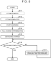
- FIG. 5 is a flowchart showing another example of the flow of charging control processing implemented by the charging control unit 31.
- the charging control unit 31 senses that fitting of the charging connector 33 of the charging device 3 and the charging inlet 25 of the vehicle 2 has started (step S11).
- the charging control unit 31 senses that fitting of the charging connector 33 of the charging device 3 and the charging inlet 25 of the vehicle 2 is complete (step S12).
- the charging control unit 31 starts charging (step S13).
- the charging control unit 31 determines, based on information regarding the SOC of the battery 21, that the battery 21 is fully charged (step S14).
- the charging control unit 31 senses that detaching of the charging connector 33 of the charging device 3 from the charging inlet 25 of the vehicle 2 has started (step S15).
- the charging control unit 31 judges whether detaching of the charging connector 33 of the charging device 3 from the charging inlet 25 of the vehicle 2 is complete (step S16).
- the charging control unit 31 judges that detaching of the charging connector 33 from the charging inlet 25 is complete (Yes in step S16)
- the series of charging control processing ends.
- the charging control unit 31 executes freezing-averting charging and discharging, assuming that the charging connector 33 and the charging inlet 25 are frozen (step S17).
- This freezing-averting charging and discharging is performed by the charging control unit 31 following judging that detaching of the charging connector 33 from the charging inlet 25 is not complete (detachment incomplete).
- discharging in which current flows from the charging inlet 25 side to the charging connector 33 side (from the battery 21 side in the vehicle 2 to the charging device 3 side), and charging in which current flows from the charging connector 33 side to the charging inlet 25 side (from the charging device 3 side to the battery 21 side in the vehicle 2) are repeated alternately so that the electric power balance is matched, thereby averting freezing of the fitting portion between the charging inlet 25 and the charging connector 33 due to heat generated by the conduction resistance at the charging inlet 25 and the charging connector 33, while maintaining the SOC of the battery 21 within a predetermined range.
- step S16 Thereafter, after executing freezing-averting charging and discharging for a certain amount of time, the flow transitions to step S16, and freezing-averting charging and discharging is repeatedly executed until detaching of the charging connector 33 from the charging inlet 25 is judged to be complete.
- the series of charging and discharging control processing ends.
- the charging connector 33 and the charging inlet 25 are judged to be frozen, and conduction between the charging inlet 25 and the charging connector 33 is performed, implementing charging and discharging such that the electric power balance is matched. Accordingly, in the charging system 1 according to the embodiment, the amount of heat generated by conduction resistance at the charging inlet 25 and the charging connector 33 can be increased even at low temperatures without separately adding a heating mechanism to the charging connector 33, thereby averting freezing of the fitting portion between the charging inlet 25 and the charging connector 33, so that the charging connector 33 can be detached from the charging inlet 25.
- the charging system 1 is not limited to an arrangement in which the user manually inserts and removes (fits and detaches) the charging connector 33 of the charging device 3 to and from the charging inlet 25 of the vehicle 2.
- an automatic charging device may be employed in which an arm mechanism is provided to the charging device 3, which holds the charging connector 33 and automatically inserts and removes (fits and detaches) the charging connector 33 to and from the charging inlet 25, thus enabling automatic charging to be performed.
- the amount of heat generated by conduction resistance at the charging inlet 25 and the charging connector 33 can be increased, thereby averting freezing of the fitting portion between the charging inlet 25 and the charging connector 33 even at low temperatures, and the charging connector 33 can be automatically detached from the charging inlet 25.
- determining whether the charging connector 33 and the charging inlet 25 are in a fitted state, and sensing of each of whether fitting has started, fitting is complete, detaching has started, and detaching is complete, and so forth, can each also be performed based on the operating state of the arm mechanism, for example, in addition to the methods described above.
- the point in time at which the arm mechanism starts to perform operations of holding the charging connector 33 and inserting the charging connector 33 into the charging inlet 25 can be sensed as the point in time at which fitting of the charging connector 33 and the charging inlet 25 is started.
Landscapes
- Engineering & Computer Science (AREA)
- Power Engineering (AREA)
- Transportation (AREA)
- Mechanical Engineering (AREA)
- Life Sciences & Earth Sciences (AREA)
- Sustainable Development (AREA)
- Sustainable Energy (AREA)
- Charge And Discharge Circuits For Batteries Or The Like (AREA)
- Electric Propulsion And Braking For Vehicles (AREA)
Abstract
A charging system fits a charging connector (33) of a charging device (3) to a charging inlet (25) of a vehicle (2) to charge a battery (21) installed in the vehicle (2). The charging system includes a temperature detecting unit configured to detect a temperature of the charging inlet (25), a usage-start-time acquisition unit (24) acquires a usage start time at which a user starts using the vehicle (2), and a control unit (31), when charging the battery, executes control, based on a detection result of the temperature detecting unit (23), to perform charging by applying, at a point in time that is immediately prior to the usage start time, a current that is greater than a current applied earlier than the point in time, when the temperature of the charging inlet (25) is lower than a threshold value temperature that is set in advance.
Description
- The invention relates to a charging system.
-
Japanese Unexamined Patent Application Publication No. 2011-167003 JP 2011-167003 A - However, the technology disclosed in
JP 2011-167003 A - The invention provides a charging system that can suppress the charging connector from becoming undetachable from the charging inlet due to freezing, while suppressing cost increases.
- A first aspect of the invention is a charging system. The charging system is configured to fit a charging connector of a charging device to a charging inlet of a vehicle to charge a battery installed in the vehicle. The charging system includes a temperature detecting unit, a usage-start-time acquisition unit, and a control unit. The temperature detecting unit is configured to detect a temperature of the charging inlet. The usage-start-time acquisition unit is configured to acquire a usage start time at which a user starts using the vehicle. The control unit is configured to, when fitting the charging inlet and the charging connector to charge the battery, execute control, based on a detection result of the temperature detecting unit, to perform charging by applying, at a point in time that is immediately prior to the usage start time, a current that is greater than a current applied earlier than the point in time, when the temperature of the charging inlet is lower than a threshold value temperature that is set in advance.
- According to the above configuration, the amount of heat generated by conduction resistance in the charging inlet and the charging connector at low temperatures can be increased in order to avert freezing of the fitting portion between the charging inlet and the charging connector, and accordingly a situation in which the charging connector cannot be detached from the charging inlet due to freezing can be suppressed, while suppressing cost increases due to adding a separate heating mechanism to the charging connector.
- In the above charging system, the control unit may increase the current of charging, from start of charging, such that the current is greater a closer to the usage start time, when the temperature of the charging inlet is lower than the threshold value temperature set in advance.
- According to the above configuration, freezing of the charging inlet and the charging connector can be averted by the usage start time.
- A second aspect of the invention is a charging system. The charging system includes a control unit that is configured to fit a charging connector of a charging device to a charging inlet of a vehicle, to charge a battery installed in the vehicle. The control unit starts detaching the charging connector from the charging inlet after charging of the battery is complete. When the charging connector cannot be detached from the charging inlet, the control unit executes control of repeatedly performing discharging in which current flows from the charging inlet side to the charging connector side and charging in which current flows from the charging connector side to the charging inlet side, alternatingly.
- According to the above configuration, the amount of heat generated by conduction resistance in the charging inlet and the charging connector can be increased by repeatedly performing charging and discharging alternatingly, to avert freezing of the fitting portion between the charging inlet and the charging connector, and accordingly a situation in which the charging connector cannot be detached from the charging inlet due to freezing can be suppressed, while suppressing cost increases due to adding a separate heating mechanism to the charging connector.
- In the charging system according to an aspect of the invention, a part of the charging connector may be made of a high thermal conductivity material.
- According to the above configuration, a great amount of heat generated by conduction resistance can be easily transferred to the fitting portion between the charging inlet and the charging connector.
- In the charging system according to an aspect of the invention, the charging device may include an arm mechanism that holds the charging connector, and automatically inserts and removes the charging connector to and from the charging inlet.
- According to the above configuration, the charging connector can be automatically detached from the charging inlet, while averting freezing of the fitting portion between the charging inlet and the charging connector, even at low temperatures.
- In the charging system according to aspects of the invention, the amount of heat generated by conduction resistance in the charging inlet and the charging connector at low temperatures can be increased to avert freezing of the fitting portion between the charging inlet and the charging connector, and accordingly advantageous effects can be obtained in that a situation in which the charging connector cannot be detached from the charging inlet due to freezing can be suppressed, while suppressing cost increases due to adding a separate heating mechanism to the charging connector.
- Features, advantages, and technical and industrial significance of exemplary embodiments of the invention will be described below with reference to the accompanying drawings, in which like signs denote like elements, and wherein:
-
FIG. 1 is a block diagram illustrating a configuration of a charging system according to an embodiment; -
FIG. 2 is a flowchart showing an example of a flow of charging control processing executed by a charging control unit; -
FIG. 3 is a diagram showing an example of a low-temperature charging profile; -
FIG. 4 is a diagram showing an example of an ordinary-temperature charging profile; -
FIG. 5 is a flowchart showing another example of the flow of charging control processing executed by the charging control unit; and -
FIG. 6 is an explanatory diagram regarding freezing-averting charging and discharging. - The following is a description of an embodiment of a charging system according to the invention. Note that the invention is not limited by the present embodiment.
-
FIG. 1 is a block diagram illustrating a configuration of a charging system 1 according to the embodiment. As illustrated inFIG. 1 , the charging system 1 according to the embodiment is a system in which acharging connector 33 of a charging device 3, installed outside of avehicle 2 such as a battery electric vehicle, is connected to acharging inlet 25 of thevehicle 2, to charge a battery 21 installed in thevehicle 2. - In this charging system 1, the
vehicle 2 side includes the battery 21, acharging control unit 22, atemperature detecting unit 23, a usage-start-time acquisition unit 24, and thecharging inlet 25. However, depending on the type ofvehicle 2, there are cases in which thetemperature detecting unit 23 and the usage-start-time acquisition unit 24 are not provided. - The battery 21 is a battery that is made up of a nickel metal hydride battery or a lithium-ion battery, for example, and that stores high-voltage direct current electric power to drive the
vehicle 2. - The
charging control unit 22 is made up of electronic circuits, principally a known microcomputer that includes a central processing unit (CPU), random access memory (RAM), read-only memory (ROM), an input/output interface, and so forth. Thecharging control unit 22 collaborates with acharging control unit 31 provided on the charging device 3 side, to control charging processing for charging the battery 21 using the charging device 3. Thecharging control unit 22 also acquires information relating to a state of charge (SOC) of the battery 21, via an in-vehicle network such as a Controller Area Network (CAN) or the like. - The
temperature detecting unit 23 is made up of a temperature sensor installed in thecharging inlet 25. Thetemperature detecting unit 23 detects temperature T of thecharging inlet 25, and outputs an electrical signal indicating the detected temperature T of thecharging inlet 25 to thecharging control unit 22. - The usage-start-time acquisition unit 24 acquires usage start time at which a user will start to use the
vehicle 2. For example, the usage-start-time acquisition unit 24 acquires the usage start time entered by the user using a communication terminal owned by the user, an input device installed in thevehicle 2, or the like, by communication thereof with the communication terminal, the input device, and so forth. - The charging
inlet 25 is made up of a conducting terminal in a housing in which is formed a hole through which thecharging connector 33 of the charging device 3 is inserted. - On the other hand, the charging device 3 side includes the
charging control unit 31, astorage unit 32, and thecharging connector 33. - The
charging control unit 31 is made up of electronic circuits, principally a microcomputer similar to that of thecharging control unit 22. Thecharging control unit 31 collaborates with thecharging control unit 22 on thevehicle 2 side to control the charging processing of charging the battery 21 via thecharging connector 33 and thecharging inlet 25. Thecharging control unit 31 also communicates with thecharging control unit 22 to obtain various types of information such as, for example, the temperature T of thecharging inlet 25 detected by thetemperature detecting unit 23, the usage start time acquired by the usage-start-time acquisition unit 24, information regarding the SOC of the battery 21, and so forth. - When the
charging connector 33 and thecharging inlet 25 are fit to each other and electrically connected, thecharging control unit 31 acquires a fitting signal indicating the fitted state from thecharging control unit 22 of thevehicle 2 via thecharging inlet 25 and thecharging connector 33, and thus determines thecharging connector 33 and thecharging inlet 25 to be in a fit state. At this time, when sensing, for example, that the fitting between thecharging connector 33 and thecharging inlet 25 has started at the point in time when the fitting signal is first acquired, and thereafter, that acquisition of the fitting signal continues for a predetermined amount of time, thecharging control unit 31 senses that the fitting between thecharging connector 33 and thecharging inlet 25 is complete. On the other hand, when the fitting signal is no longer acquired, thecharging control unit 31 determines that thecharging connector 33 is detached from thecharging inlet 25, and that the fit state between thecharging connector 33 and thecharging inlet 25 has been dissolved (detached state). At this time, when sensing, for example, that detaching of thecharging connector 33 from the charginginlet 25 is started at the point in time when the fitting signal is first no longer acquired, and thereafter, when non-acquisition of the fitting signal continues for a predetermined amount of time, thecharging control unit 31 senses that the detaching of thecharging connector 33 from thecharging inlet 25 is complete. Note that the respective methods of determining whether thecharging connector 33 and thecharging inlet 25 are in a fitted state, the method of sensing that fitting has started, that fitting is complete, that detaching has started, and that detaching is complete, and so forth, are not limited in particular, and known technology can be employed. - The
storage unit 32 stores information used in implementing charging control by thecharging control unit 31, such as an ordinary-temperature charging profile and a low-temperature charging profile, for example. - The
charging connector 33 is made up of a conducting terminal that is electrically connected to the conducting terminal of thecharging inlet 25 when inserted into the charginginlet 25 of thevehicle 2, and a holding unit that holds the conducting terminal. The holding unit of thecharging connector 33 is made of a high thermal conductivity material, such as a resin material that has relatively high thermal conductivity. - In the charging system 1 having this configuration, the
charging control unit 31 on the charging device 3 side executes the charging control processing described below to charge the battery 21, while averting freezing of thecharging connector 33. The following is a description of operations of the chargingcontrol unit 31 when executing the charging control processing. -
FIG. 2 is a flowchart showing an example of a flow of the charging control processing implemented by the chargingcontrol unit 31. First, the chargingcontrol unit 31 senses that fitting of the chargingconnector 33 of the charging device 3 and the charginginlet 25 of thevehicle 2 has started (step S1). Next, the chargingcontrol unit 31 senses that fitting of the chargingconnector 33 of the charging device 3 and the charginginlet 25 of thevehicle 2 is complete (step S2). Next, the chargingcontrol unit 31 starts charging (step S3). Next, the chargingcontrol unit 31 judges whether the temperature T of the charginginlet 25 detected by thetemperature detecting unit 23 is lower than a threshold value temperature T0 set in advance (step S4). Note that the threshold value temperature T0 is defined as a low temperature, such that freezing of the chargingconnector 33 and the charginginlet 25 may occur below this threshold value temperature T0. - When judging that the temperature T of the charging
inlet 25 is lower than the threshold value temperature T0 (Yes in step S4), the chargingcontrol unit 31 acquires the usage start time at which the user will start to use thevehicle 2, from the usage-start-time acquisition unit 24 (step S5). Note that here, the usage start time at which the user will start to use thevehicle 2 is defined as a departure time at which the user enters thevehicle 2 and departs. Next, the chargingcontrol unit 31 executes charging using the low-temperature charging profile stored in the storage unit 32 (step S6). -
FIG. 3 is a diagram showing an example of the low-temperature charging profile. In charging using the low-temperature charging profile, the battery 21 is charged by applying a current so that the battery 21 is fully charged by the acquired departure time (usage start time). At this time, as shown inFIG. 3 , from the start of charging, the chargingcontrol unit 31 gradually increases the current the closer to the departure time (usage start time), and in the latter half of the charging, immediately prior to the departure time (usage start time), increases the current to a greater current than that so far, and performs charging by applying the greatest current (high current) set in the low-temperature charging profile. After the chargingcontrol unit 31 executes charging using the low-temperature charging profile, the flow transitions to the processing in step S8. - On the other hand, when the charging
control unit 31 judges in the processing in step S4 that the temperature T of the charginginlet 25 is no lower than the threshold value temperature T0 (No in step S4), charging is executed using the ordinary-temperature charging profile (step S7). -
FIG. 4 is a diagram showing an example of the ordinary-temperature charging profile. In charging using the ordinary-temperature charging profile, the battery 21 is charged by applying current so that the battery 21 is fully charged at an earliest possible time from the start of charging. At this time, as shown inFIG. 4 , the chargingcontrol unit 31 applies the greatest current (high current) set in the ordinary-temperature charging profile from the time of the start of charging, and as the battery 21 approaches a full charge, the current is gradually reduced, and in the latter half of the charge, a low current is applied to charge the battery. After the chargingcontrol unit 31 executes charging using the ordinary-temperature charging profile, the flow then transitions to the processing in step S8. - The charging
control unit 31 executes charging using the low-temperature charging profile or the ordinary-temperature charging profile, and based on information regarding the SOC of the battery 21, determines that the battery 21 is fully charged (step S8). Next, the chargingcontrol unit 31 senses that detaching of the chargingconnector 33 of the charging device 3 from the charginginlet 25 of thevehicle 2 has started (step S9). Next, the chargingcontrol unit 31 senses that detaching of the chargingconnector 33 of the charging device 3 from the charginginlet 25 of thevehicle 2 is complete (step S10). The chargingcontrol unit 31 then ends the charging control processing according to one example. - In the charging system 1 according to the embodiment, at the time of the start of charging, the temperature T of the charging
inlet 25 is detected by thetemperature detecting unit 23 installed in thevehicle 2, the detected temperature T is compared with the threshold value temperature T0 to judge whether the fitting portion between the charginginlet 25 and the chargingconnector 33 may possibly freeze, and when the temperature T is lower than the threshold value temperature T0, the usage start time at which the user will start using thevehicle 2, such as the departure time, is acquired, and thereafter charging is executed using the low-temperature charging profile. In charging using this low-temperature charging profile, conduction of a high current is performed immediately prior to the usage start time (departure time), and accordingly the amount of heat generated at the charginginlet 25 and the chargingconnector 33 due to conduction resistance can be increased as compared to when conduction of a low current is performed in the latter half of charging, such as in charging using the ordinary-temperature charging profile. In particular, in the charging system 1 according to the embodiment, a part (the holding unit) of the chargingconnector 33 is made of a high thermal conductivity material, and accordingly, a great amount of heat generated by the conduction resistance can be easily transferred to the fitting portion between the charginginlet 25 and the chargingconnector 33. - Accordingly, in the charging system 1 according to the embodiment, the amount of heat generated by conduction resistance at the charging
inlet 25 and the chargingconnector 33 can be increased without adding a heating mechanism to the chargingconnector 33, thereby heating the fitting portion between the charginginlet 25 and the chargingconnector 33 by the usage start time (departure time) even at low temperatures, and averting freezing. Thus, in the charging system 1 according to the embodiment, the chargingconnector 33 can be suppressed from becoming undetachable from the charginginlet 25 due to freezing, while suppressing cost increases. -
FIG. 5 is a flowchart showing another example of the flow of charging control processing implemented by the chargingcontrol unit 31. First, the chargingcontrol unit 31 senses that fitting of the chargingconnector 33 of the charging device 3 and the charginginlet 25 of thevehicle 2 has started (step S11). Next, the chargingcontrol unit 31 senses that fitting of the chargingconnector 33 of the charging device 3 and the charginginlet 25 of thevehicle 2 is complete (step S12). Next, the chargingcontrol unit 31 starts charging (step S13). The chargingcontrol unit 31 determines, based on information regarding the SOC of the battery 21, that the battery 21 is fully charged (step S14). Next, the chargingcontrol unit 31 senses that detaching of the chargingconnector 33 of the charging device 3 from the charginginlet 25 of thevehicle 2 has started (step S15). Next, the chargingcontrol unit 31 judges whether detaching of the chargingconnector 33 of the charging device 3 from the charginginlet 25 of thevehicle 2 is complete (step S16). When the chargingcontrol unit 31 judges that detaching of the chargingconnector 33 from the charginginlet 25 is complete (Yes in step S16), the series of charging control processing ends. On the other hand, when judging that detaching of the chargingconnector 33 from the charginginlet 25 is not complete (No in step S16), the chargingcontrol unit 31 executes freezing-averting charging and discharging, assuming that the chargingconnector 33 and the charginginlet 25 are frozen (step S17). - This freezing-averting charging and discharging is performed by the charging
control unit 31 following judging that detaching of the chargingconnector 33 from the charginginlet 25 is not complete (detachment incomplete). As shown inFIG. 6 , discharging in which current flows from the charginginlet 25 side to the chargingconnector 33 side (from the battery 21 side in thevehicle 2 to the charging device 3 side), and charging in which current flows from the chargingconnector 33 side to the charginginlet 25 side (from the charging device 3 side to the battery 21 side in the vehicle 2) are repeated alternately so that the electric power balance is matched, thereby averting freezing of the fitting portion between the charginginlet 25 and the chargingconnector 33 due to heat generated by the conduction resistance at the charginginlet 25 and the chargingconnector 33, while maintaining the SOC of the battery 21 within a predetermined range. - Thereafter, after executing freezing-averting charging and discharging for a certain amount of time, the flow transitions to step S16, and freezing-averting charging and discharging is repeatedly executed until detaching of the charging
connector 33 from the charginginlet 25 is judged to be complete. Upon the chargingcontrol unit 31 judging that detaching of the chargingconnector 33 from the charginginlet 25 is complete (Yes in step S16), the series of charging and discharging control processing ends. - In the charging system 1 according to the embodiment, when the charging
connector 33 cannot be detached from the charginginlet 25 at the time of the end of charging, the chargingconnector 33 and the charginginlet 25 are judged to be frozen, and conduction between the charginginlet 25 and the chargingconnector 33 is performed, implementing charging and discharging such that the electric power balance is matched. Accordingly, in the charging system 1 according to the embodiment, the amount of heat generated by conduction resistance at the charginginlet 25 and the chargingconnector 33 can be increased even at low temperatures without separately adding a heating mechanism to the chargingconnector 33, thereby averting freezing of the fitting portion between the charginginlet 25 and the chargingconnector 33, so that the chargingconnector 33 can be detached from the charginginlet 25. - Note that the charging system 1 according to the embodiment is not limited to an arrangement in which the user manually inserts and removes (fits and detaches) the charging
connector 33 of the charging device 3 to and from the charginginlet 25 of thevehicle 2. For example, an automatic charging device may be employed in which an arm mechanism is provided to the charging device 3, which holds the chargingconnector 33 and automatically inserts and removes (fits and detaches) the chargingconnector 33 to and from the charginginlet 25, thus enabling automatic charging to be performed. Thus, when charging the battery 21 of thevehicle 2 by the automatic charging device, the amount of heat generated by conduction resistance at the charginginlet 25 and the chargingconnector 33 can be increased, thereby averting freezing of the fitting portion between the charginginlet 25 and the chargingconnector 33 even at low temperatures, and the chargingconnector 33 can be automatically detached from the charginginlet 25. - Note that when the automatic charging device is used, determining whether the charging
connector 33 and the charginginlet 25 are in a fitted state, and sensing of each of whether fitting has started, fitting is complete, detaching has started, and detaching is complete, and so forth, can each also be performed based on the operating state of the arm mechanism, for example, in addition to the methods described above. For example, the point in time at which the arm mechanism starts to perform operations of holding the chargingconnector 33 and inserting the chargingconnector 33 into the charginginlet 25 can be sensed as the point in time at which fitting of the chargingconnector 33 and the charginginlet 25 is started.
Claims (7)
- A charging system (1) that is configured to fit a charging connector (33) of a charging device (3) to a charging inlet (25) of a vehicle (2) to charge a battery installed in the vehicle (2), the charging system (1) comprising:a temperature detecting unit (23) configured to detect a temperature of the charging inlet (25);a usage-start-time acquisition unit (24) configured to acquire a usage start time at which a user starts using the vehicle (2); anda control unit (31) configured to, when fitting the charging inlet (25) and the charging connector (33) to charge the battery, execute control, based on a detection result of the temperature detecting unit (23), to perform charging by applying, at a point in time that is immediately prior to the usage start time, a current that is greater than a current applied earlier than the point in time, when the temperature of the charging inlet (25) is lower than a threshold value temperature that is set in advance.
- The charging system (1) according to claim 1, wherein the control unit (31) increases the current of charging, from start of charging, such that the current is greater a closer to the usage start time, when the temperature of the charging inlet (25) is lower than the threshold value temperature set in advance.
- The charging system (1) according to claim 1 or 2, wherein a part of the charging connector (33) is made of a high thermal conductivity material.
- The charging system (1) according to claim 1 or 2, wherein the charging device (3) includes an arm mechanism that holds the charging connector (33), and automatically inserts and removes the charging connector (33) to and from the charging inlet (25).
- A charging system (1) configured to fit a charging connector (33) of a charging device (3) to a charging inlet (25) of a vehicle to charge a battery installed in the vehicle, the charging system (1) comprising a control unit (31) configured to charge the battery by fitting the charging inlet (25) and the charging connector (33) to each other, wherein the control unit (31) is configured to:start detaching the charging connector (33) from the charging inlet (25) after charging of the battery is complete; andwhen the charging connector (33) cannot be detached from the charging inlet (25), execute control of repeatedly performing discharging in which current flows from the charging inlet (25) side to the charging connector (33) side and charging in which current flows from the charging connector (33) side to the charging inlet (25) side, alternatingly.
- The charging system (1) according to claim 5, wherein a part of the charging connector (33) is made of a high thermal conductivity material.
- The charging system (1) according to claim 5, wherein the charging device (3) includes an arm mechanism that holds the charging connector (33), and automatically inserts and removes the charging connector (33) to and from the charging inlet (25).
Applications Claiming Priority (1)
| Application Number | Priority Date | Filing Date | Title |
|---|---|---|---|
| JP2022063076A JP7779191B2 (en) | 2022-04-05 | 2022-04-05 | Charging system |
Publications (1)
| Publication Number | Publication Date |
|---|---|
| EP4257416A1 true EP4257416A1 (en) | 2023-10-11 |
Family
ID=85150238
Family Applications (1)
| Application Number | Title | Priority Date | Filing Date |
|---|---|---|---|
| EP23153973.5A Pending EP4257416A1 (en) | 2022-04-05 | 2023-01-30 | Charging system |
Country Status (5)
| Country | Link |
|---|---|
| US (1) | US20230311689A1 (en) |
| EP (1) | EP4257416A1 (en) |
| JP (1) | JP7779191B2 (en) |
| KR (1) | KR20230143554A (en) |
| CN (1) | CN116890683A (en) |
Citations (7)
| Publication number | Priority date | Publication date | Assignee | Title |
|---|---|---|---|---|
| JP2011167003A (en) | 2010-02-12 | 2011-08-25 | Honda Motor Co Ltd | Charging apparatus and charging system |
| JP2017212842A (en) * | 2016-05-27 | 2017-11-30 | 三菱自動車工業株式会社 | Electric vehicle |
| JP2020156250A (en) * | 2019-03-22 | 2020-09-24 | 株式会社Subaru | Vehicle control device |
| JP6796571B2 (en) * | 2017-11-06 | 2020-12-09 | 本田技研工業株式会社 | Vehicle control systems, vehicle control methods, and programs |
| US20210013728A1 (en) * | 2019-07-09 | 2021-01-14 | Toyota Jidosha Kabushiki Kaisha | Charging controller |
| US20210053451A1 (en) * | 2019-08-22 | 2021-02-25 | Ford Global Technologies, Llc | Automatic, hands-free conductive charging system for electric vehicle applications |
| KR20210065614A (en) * | 2019-11-27 | 2021-06-04 | 엘에스이브이코리아 주식회사 | Electric Vehicle Charging Connector and Electric Vehicle Charging Assembly |
Family Cites Families (8)
| Publication number | Priority date | Publication date | Assignee | Title |
|---|---|---|---|---|
| JP2018102084A (en) * | 2016-12-21 | 2018-06-28 | トヨタ自動車株式会社 | Charge control device |
| US10369898B2 (en) * | 2017-01-17 | 2019-08-06 | Nio Usa, Inc. | Rechargeable vehicle thermal management charging system |
| JP2019197641A (en) * | 2018-05-09 | 2019-11-14 | トヨタ自動車株式会社 | connector |
| JP6497478B1 (en) * | 2018-11-02 | 2019-04-10 | トヨタ自動車株式会社 | Charging system |
| CN109969019A (en) * | 2019-04-29 | 2019-07-05 | 上海蔚来汽车有限公司 | Charging gun heating means, heating device and charging gun |
| JP7310722B2 (en) * | 2020-06-02 | 2023-07-19 | トヨタ自動車株式会社 | Power storage system and vehicle |
| CN114074571B (en) * | 2020-08-13 | 2024-02-27 | 比亚迪股份有限公司 | Vehicle charging method and device, storage medium and vehicle |
| CN112060964A (en) * | 2020-08-18 | 2020-12-11 | 金龙联合汽车工业(苏州)有限公司 | Battery heating strategy optimization method based on charging capacity of battery and charging pile |
-
2022
- 2022-04-05 JP JP2022063076A patent/JP7779191B2/en active Active
-
2023
- 2023-01-18 KR KR1020230007467A patent/KR20230143554A/en not_active Ceased
- 2023-01-30 EP EP23153973.5A patent/EP4257416A1/en active Pending
- 2023-01-30 US US18/103,063 patent/US20230311689A1/en active Pending
- 2023-03-31 CN CN202310332676.XA patent/CN116890683A/en active Pending
Patent Citations (7)
| Publication number | Priority date | Publication date | Assignee | Title |
|---|---|---|---|---|
| JP2011167003A (en) | 2010-02-12 | 2011-08-25 | Honda Motor Co Ltd | Charging apparatus and charging system |
| JP2017212842A (en) * | 2016-05-27 | 2017-11-30 | 三菱自動車工業株式会社 | Electric vehicle |
| JP6796571B2 (en) * | 2017-11-06 | 2020-12-09 | 本田技研工業株式会社 | Vehicle control systems, vehicle control methods, and programs |
| JP2020156250A (en) * | 2019-03-22 | 2020-09-24 | 株式会社Subaru | Vehicle control device |
| US20210013728A1 (en) * | 2019-07-09 | 2021-01-14 | Toyota Jidosha Kabushiki Kaisha | Charging controller |
| US20210053451A1 (en) * | 2019-08-22 | 2021-02-25 | Ford Global Technologies, Llc | Automatic, hands-free conductive charging system for electric vehicle applications |
| KR20210065614A (en) * | 2019-11-27 | 2021-06-04 | 엘에스이브이코리아 주식회사 | Electric Vehicle Charging Connector and Electric Vehicle Charging Assembly |
Also Published As
| Publication number | Publication date |
|---|---|
| KR20230143554A (en) | 2023-10-12 |
| JP7779191B2 (en) | 2025-12-03 |
| JP2023153676A (en) | 2023-10-18 |
| CN116890683A (en) | 2023-10-17 |
| US20230311689A1 (en) | 2023-10-05 |
Similar Documents
| Publication | Publication Date | Title |
|---|---|---|
| JP5102483B2 (en) | Abnormality detection device, abnormality detection method, and abnormality detection program | |
| US12085626B2 (en) | Battery cell diagnosing apparatus and method | |
| JP4866187B2 (en) | Battery control device, electric vehicle, and program for causing computer to execute processing for estimating charge state of secondary battery | |
| EP2579381B1 (en) | System and method for determination of deterioration of lithium ion secondary battery | |
| US20220179008A1 (en) | Battery Diagnosing Apparatus and Method | |
| WO2005036192A1 (en) | Secondary battery residual capacity calculating apparatus and calculating method | |
| JP4457781B2 (en) | Deterioration degree estimation method and deterioration degree estimation apparatus | |
| CN106208168A (en) | Estimate the system of electric vehicle battery health status | |
| EP3726639A1 (en) | Rechargeable battery temperature estimation device and rechargeable battery temperature estimation method | |
| JP4193745B2 (en) | Battery state detection method and battery state detection device | |
| CN111002871A (en) | charging device | |
| EP3611817A1 (en) | Appratus and method of controlling battery | |
| CN112829635A (en) | Lithium evolution detection and mitigation in electric vehicle batteries | |
| US20030184261A1 (en) | Method of charging a storage battery | |
| CN112265465A (en) | Power battery charging method and device, electric vehicle and electronic equipment | |
| US20100060241A1 (en) | Method and device for determining an equalizing charge of an accumulator | |
| EP4257416A1 (en) | Charging system | |
| CN116859244A (en) | Method and device for identifying abnormal battery cells, server and storage medium | |
| JP2007024825A (en) | Current sensor failure diagnosis device | |
| JP2003254839A (en) | Temperature sensor status detection device and status detection method | |
| JPH1138107A (en) | Remaining battery capacity estimation method | |
| JP2003070169A (en) | Method for determining deterioration of lead storage battery for vehicle | |
| CN111263999A (en) | Management device, power storage device, cause analysis method, engine-driven vehicle, electric vehicle | |
| EP2998754B1 (en) | Secondary battery status detection device and secondary battery status detection method | |
| US20060136163A1 (en) | Offset correction apparatus and offset correction method for automotive voltage sensor |
Legal Events
| Date | Code | Title | Description |
|---|---|---|---|
| PUAI | Public reference made under article 153(3) epc to a published international application that has entered the european phase |
Free format text: ORIGINAL CODE: 0009012 |
|
| STAA | Information on the status of an ep patent application or granted ep patent |
Free format text: STATUS: REQUEST FOR EXAMINATION WAS MADE |
|
| 17P | Request for examination filed |
Effective date: 20230130 |
|
| AK | Designated contracting states |
Kind code of ref document: A1 Designated state(s): AL AT BE BG CH CY CZ DE DK EE ES FI FR GB GR HR HU IE IS IT LI LT LU LV MC ME MK MT NL NO PL PT RO RS SE SI SK SM TR |
|
| STAA | Information on the status of an ep patent application or granted ep patent |
Free format text: STATUS: EXAMINATION IS IN PROGRESS |
|
| 17Q | First examination report despatched |
Effective date: 20251215 |