EP4256924A1 - Combine harvester and travel route correction method - Google Patents
Combine harvester and travel route correction method Download PDFInfo
- Publication number
- EP4256924A1 EP4256924A1 EP21900327.4A EP21900327A EP4256924A1 EP 4256924 A1 EP4256924 A1 EP 4256924A1 EP 21900327 A EP21900327 A EP 21900327A EP 4256924 A1 EP4256924 A1 EP 4256924A1
- Authority
- EP
- European Patent Office
- Prior art keywords
- straight
- line course
- course
- correction
- line
- Prior art date
- Legal status (The legal status is an assumption and is not a legal conclusion. Google has not performed a legal analysis and makes no representation as to the accuracy of the status listed.)
- Pending
Links
Images




Classifications
-
- G—PHYSICS
- G05—CONTROLLING; REGULATING
- G05D—SYSTEMS FOR CONTROLLING OR REGULATING NON-ELECTRIC VARIABLES
- G05D1/00—Control of position, course, altitude or attitude of land, water, air or space vehicles, e.g. using automatic pilots
- G05D1/02—Control of position or course in two dimensions
- G05D1/021—Control of position or course in two dimensions specially adapted to land vehicles
- G05D1/0212—Control of position or course in two dimensions specially adapted to land vehicles with means for defining a desired trajectory
- G05D1/0219—Control of position or course in two dimensions specially adapted to land vehicles with means for defining a desired trajectory ensuring the processing of the whole working surface
-
- A—HUMAN NECESSITIES
- A01—AGRICULTURE; FORESTRY; ANIMAL HUSBANDRY; HUNTING; TRAPPING; FISHING
- A01D—HARVESTING; MOWING
- A01D41/00—Combines, i.e. harvesters or mowers combined with threshing devices
- A01D41/12—Details of combines
- A01D41/127—Control or measuring arrangements specially adapted for combines
- A01D41/1278—Control or measuring arrangements specially adapted for combines for automatic steering
-
- A—HUMAN NECESSITIES
- A01—AGRICULTURE; FORESTRY; ANIMAL HUSBANDRY; HUNTING; TRAPPING; FISHING
- A01B—SOIL WORKING IN AGRICULTURE OR FORESTRY; PARTS, DETAILS, OR ACCESSORIES OF AGRICULTURAL MACHINES OR IMPLEMENTS, IN GENERAL
- A01B69/00—Steering of agricultural machines or implements; Guiding agricultural machines or implements on a desired track
- A01B69/007—Steering or guiding of agricultural vehicles, e.g. steering of the tractor to keep the plough in the furrow
- A01B69/008—Steering or guiding of agricultural vehicles, e.g. steering of the tractor to keep the plough in the furrow automatic
-
- A—HUMAN NECESSITIES
- A01—AGRICULTURE; FORESTRY; ANIMAL HUSBANDRY; HUNTING; TRAPPING; FISHING
- A01D—HARVESTING; MOWING
- A01D41/00—Combines, i.e. harvesters or mowers combined with threshing devices
- A01D41/12—Details of combines
- A01D41/127—Control or measuring arrangements specially adapted for combines
-
- G—PHYSICS
- G05—CONTROLLING; REGULATING
- G05D—SYSTEMS FOR CONTROLLING OR REGULATING NON-ELECTRIC VARIABLES
- G05D1/00—Control of position, course, altitude or attitude of land, water, air or space vehicles, e.g. using automatic pilots
- G05D1/20—Control system inputs
- G05D1/22—Command input arrangements
- G05D1/221—Remote-control arrangements
- G05D1/222—Remote-control arrangements operated by humans
- G05D1/224—Output arrangements on the remote controller, e.g. displays, haptics or speakers
- G05D1/2244—Optic
- G05D1/2245—Optic providing the operator with a purely computer-generated representation of the environment of the vehicle, e.g. virtual reality
-
- G—PHYSICS
- G05—CONTROLLING; REGULATING
- G05D—SYSTEMS FOR CONTROLLING OR REGULATING NON-ELECTRIC VARIABLES
- G05D1/00—Control of position, course, altitude or attitude of land, water, air or space vehicles, e.g. using automatic pilots
- G05D1/40—Control within particular dimensions
- G05D1/43—Control of position or course in two dimensions [2D]
-
- G—PHYSICS
- G05—CONTROLLING; REGULATING
- G05D—SYSTEMS FOR CONTROLLING OR REGULATING NON-ELECTRIC VARIABLES
- G05D1/00—Control of position, course, altitude or attitude of land, water, air or space vehicles, e.g. using automatic pilots
- G05D1/60—Intended control result
- G05D1/648—Performing a task within a working area or space, e.g. cleaning
-
- G—PHYSICS
- G05—CONTROLLING; REGULATING
- G05D—SYSTEMS FOR CONTROLLING OR REGULATING NON-ELECTRIC VARIABLES
- G05D2105/00—Specific applications of the controlled vehicles
- G05D2105/15—Specific applications of the controlled vehicles for harvesting, sowing or mowing in agriculture or forestry
-
- G—PHYSICS
- G05—CONTROLLING; REGULATING
- G05D—SYSTEMS FOR CONTROLLING OR REGULATING NON-ELECTRIC VARIABLES
- G05D2107/00—Specific environments of the controlled vehicles
- G05D2107/20—Land use
- G05D2107/21—Farming, e.g. fields, pastures or barns
-
- G—PHYSICS
- G05—CONTROLLING; REGULATING
- G05D—SYSTEMS FOR CONTROLLING OR REGULATING NON-ELECTRIC VARIABLES
- G05D2109/00—Types of controlled vehicles
- G05D2109/10—Land vehicles
Definitions
- the present invention relates to a combine harvester that, in a case when a movement of a straight-line course in which an automatic reaping travel is conducted is to be made midway in the straight-line course, corrects another adjacent straight-line course, and a travel route correction method for correcting a travel route of the combine harvester.
- the selecting step enables selection of correction of the second straight-line course.
- any of a variety of turning methods may be set for the turn between the courses of the go-and-return reaping, including a U-shaped turn that is a basic turning method in which a 180-degree-turn is conducted only by moving forward, and a fishtail turn in which the combine harvester returns after a 90-degree-tum is conducted by moving forward, and then, another 90-degree-turn is conducted by moving forward.
- the turning method may be set according to a process between courses, or may be set according to an operation of the worker.
- a base station 39 may be provided on a ridge, etc. surrounding the farm field that is to be the work target of the combine harvester 1.
- the base station 39 includes a stationary communication device 40, a stationary GPS antenna 41, and a data sending antenna 42.
- the stationary communication device 40 communicates with a GPS satellite by the stationary GPS antenna 41 to acquire a position information of the base station 39.
- the stationary communication device 40 sends a correction information based on the position information of the base station 39 to the mobile communication device 35 via the data sending antenna 42.
- the mobile terminal 53 is a terminal capable of remotely controlling the combine harvester 1, and is composed of a tablet type terminal or a laptop type personal computer, etc. including a display unit 54 such as a touch panel.
- the operation tools 30 or the automatic drive operation unit 31 similar to the mobile terminal 53 may be included in the operation unit 9.
- the mobile terminal 53 may include a portable camera 55 that takes an image.
- the portable camera 55 takes an image of the farm field of the work target to acquire the farm field image.
- the portable camera 55 may not be included and the acquisition of the farm field information by the portable camera 55 may not be conducted.
- the mobile terminal 53 is configured to accept an input operation by a touch operation, etc. on the touch panel for the farm field information about the farm field of the work target. For example, the mobile terminal 53 displays a farm field information setting screen on which a shape, a size, and position information (such as coordinates), etc. of the edge of the farm field that configures an outer periphery of the farm field, and shapes, sizes, and position information (such as coordinates), etc. of the headland (already-reaped region) and the yet-to-be-reaped region of the farm field can be set as the farm field information.
- the mobile terminal 53 may display the farm field map based on the farm field information on the display unit 54 similarly to the automatic drive operation unit 31.
- the course movement unit 63 translates a part of the first straight-line course R1a after the order of the movement according to an operation of the movement switch of the automatic drive operation unit 31 to modify the travel route.
- the first straight-line course R1a is preferably moved toward the row of the yet-to-be-reaped cereal culms.
- the first straight-line course R1a after the order of the movement is drawn in a dashed line before the movement and is drawn in a solid line after the movement.
- the course correction unit 64 corrects the second straight-line course R2b that is adjacent to the first straight-line course R2a in the travel route P2 of the go-and-return reaping so that the second straight-line course R2b will be parallel to the line connecting the start point and the end point of the first straight-line course R2a.
Landscapes
- Engineering & Computer Science (AREA)
- Life Sciences & Earth Sciences (AREA)
- Environmental Sciences (AREA)
- Physics & Mathematics (AREA)
- Radar, Positioning & Navigation (AREA)
- Remote Sensing (AREA)
- Aviation & Aerospace Engineering (AREA)
- General Physics & Mathematics (AREA)
- Automation & Control Theory (AREA)
- Mechanical Engineering (AREA)
- Soil Sciences (AREA)
- Guiding Agricultural Machines (AREA)
- Combines (AREA)
- Control Of Position, Course, Altitude, Or Attitude Of Moving Bodies (AREA)
Abstract
Description
- The present invention relates to a combine harvester that, in a case when a movement of a straight-line course in which an automatic reaping travel is conducted is to be made midway in the straight-line course, corrects another adjacent straight-line course, and a travel route correction method for correcting a travel route of the combine harvester.
- Conventionally, the combine harvester, which reaps cereal culms while traveling in a farm field, can conduct an automatic reaping travel according to a preset travel route based on a position information of the device of the combine harvester that is acquired using a satellite positioning system such as a GPS.
- The travel route is created by combining a plurality of straight-line courses in which an automatic reaping travel is to be conducted. Even if the combine harvester conducts the automatic reaping travel according to the straight-line courses of the preset travel route, rows of yet-to-be-reaped cereal culms may deviate from the straight-line course. Therefore, in the combine harvester, an operator may manually adjust direction during the automatic reaping travel of the straight-line course. For example, the combine harvester translates the on-going straight-line course midway in the automatic reaping travel (so-called, pass offset) and continues the automatic reaping travel on the straight-line course after the translation.
- For example, in the travel work machine disclosed in the
Patent Literature 1, a travel machine body conducts a travel by repeating a straight-line-shaped travel route in which the travel machine body conducts an automatic steering travel straightly while working, and a change-in-direction route in which the travel machine body conducts a manual steering travel to change the direction from the travel end portion of the straight-line-shaped travel route without working. A target travel route adjusting unit of the travel work machine sets a target travel route that has been translated from the original target travel route based on the input by the manual operation as a target travel route on which the travel machine body will travel without translation of the route of the travel machine body midway in the automatic steering travel. Further, the target travel route adjusting unit automatically adjusts the target travel route from the target travel route section that has been adjusted based on the input by the manual operation based on the adjustment amount of the target travel route section. - Patent Literature 1:
JP6415880 - In the conventional combine harvester, there is a combine harvester that translates the straight-line course midway in the automatic reaping travel and continues the automatic reaping travel of the straight-line course after the translation. However, this combine harvester does not specifically modify another straight-line course following the straight-line course and the modification process such as a translation is needed each time when the work of the straight-line course is conducted. Therefore, a worker needs to decide and operate the correction process each time when the work of the straight-line course is conducted, and this causes a problem that it takes a lot of effort of the worker.
- In the
Patent Literature 1, there is described an adjustment of the target travel route from the target travel route section that has been adjusted based on the input by the manual operation. However, there is not described for what and how the target travel route is adjusted. For example, there is a problem that, even if the automatic reaping travel of the following straight-line course is continued when the straight-line course of the combine harvester is translated midway in the automatic reaping travel, cereal culms that are not reaped remain. However, the technique described in a prior art andPatent Literature 1 cannot solve the above-described problem. - The object of the present invention is to provide a combine harvester and a travel route correction method that, in a case when a movement of a straight-line course in which an automatic reaping travel is to be conducted is to be made midway in the straight-line course, can appropriately correct another adjacent straight-line course.
- In order to solve the above-described problem, a combine harvester according to the present invention is a combine harvester that conducts an automatic reaping travel according to a travel route, characterized in that the combine harvester including: a travel route creation unit that creates the travel route including at least a first straight-line course and a second straight-line course parallel to and adjacent to the first straight-line course in a yet-to-be-reaped region in a farm field; an automatic drive control unit that controls automatic traveling and automatic reaping according to the travel route; a course movement unit that moves the first straight-line course in a direction intersecting with a forward direction to correct the travel route while conducting the automatic reaping travel of the first straight-line course; and a course correction unit that, when the first straight-line course is moved to one direction, inclines at least a part of the second straight-line course to the one direction to correct the second straight-line course.
- In the combine harvester of the present invention described above, it is preferable that, when an end point of the first straight-line course is moved to one direction by a movement of the first straight-line course, the course correction unit inclines the second straight-line course to the one direction to correct the part of the second straight-line course.
- In the combine harvester of the present invention described above, it is preferable that: the combine harvester further includes a correction selecting unit that selects whether the second straight-line course is to be corrected or not when the translation of the first straight-line course is conducted; and the course correction unit modifies the second straight-line course when performance of correction is selected by the correction selecting unit.
- In the combine harvester of the present invention described above, it is preferable that, when a straight line connecting a start point and an end point of the first straight-line course is inclined by an angle equal to or larger than a predetermined angle between before and after movement of the first straight-line course, the correction selecting unit enables selection of correction of the second straight-line course.
- In the combine harvester of the present invention described above, it is preferable that: the combine harvester further includes a display unit that displays the travel route along with a shape of the farm field; the correction selecting unit displays the second straight-line course before correction and the second straight-line course after correction in different displaying manners on the display unit to enable selection of any one of the second straight-line course before correction and the second straight-line course after correction.
- In the combine harvester of the present invention described above, it is preferable that the correction selecting unit displays a reaping width of the second straight-line course that is temporarily selected from the second straight-line course before correction and the second straight-line course after correction on the display unit.
- Further, in order to solve the above-described problem, a travel route correction method according to the present invention is a travel route correction method that corrects a travel route in which a combine harvester conducts an automatic reaping travel, characterized in that: the travel route correction method including: a moving step of moving, in the travel route including at least a first straight-line course and a second straight-line course parallel to and adjacent to the first straight-line course in a yet-to-be-reaped region in a farm field, the first straight-line course in a direction intersecting with a forward direction to correct the travel route while conducting the automatic reaping travel of the first straight-line course; and a correcting step of inclining, when the first straight-line course is moved to one direction, at least a part of the second straight-line course in one direction to correct the part of the second straight-line course.
- In the travel route correction method of the present invention described above, it is preferable that, when an end point of the first straight-line course is moved to one direction by movement of the first straight-line course, the correcting step inclines the second straight-line course to the one direction to correct the second straight-line course.
- In the travel route correction method of the present invention described above, it is preferable that: the moving step conducts translation of the first straight-line course to corrects the travel route; the travel route correction method further includes a selecting step of selecting whether the second straight-line course is to be corrected or not when the translation of the first straight-line course is conducted; the correcting step conducts correction of the second straight-line course when the correction is selected by the selecting step.
- In the travel route correction method of the present invention described above, it is preferable that, when a straight line connecting a start point and an end point of the first straight-line course is inclined by an angle equal to or larger than a predetermined angle between before and after movement of the first straight-line course, the selecting step enables selection of correction of the second straight-line course.
- In the travel route correction method of the present invention described above, it is preferable that: the selecting step displays the second straight-line course before correction and the second straight-line course after correction in different displaying manners on a display unit of the combine harvester that displays the travel route along with a shape of the farm field to enable selection of any one of the second straight-line course before correction and the second straight-line course after correction.
- In the travel route correction method of the present invention described above, it is preferable that the selecting step displays a reaping width of the second straight-line course that is temporarily selected from the second straight-line course before correction and the second straight-line course after correction on the display unit.
- According to the present invention, there are provided a combine harvester and a travel route correction method that, in a case when a movement of a straight-line course in which an automatic reaping travel is to be conducted is to be made midway in the straight-line course, can appropriately correct another adjacent straight-line course.
-
-
FIG. 1 is a side view of a combine harvester according to an embodiment of the present invention. -
FIG. 2 is a block diagram of a mobile station and a base station of the combine harvester according to the embodiment of the present invention. -
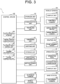
FIG. 3 is a block diagram of the combine harvester according to the embodiment of the present invention. -
FIG. 4 is a plan view of a first example operation of a movement of an on-going first straight-line course and a correlation of an adjacent second straight-line course in the combine harvester according to the embodiment of the inclusion. -
FIG. 5 is a plan view of a second example operation of a movement of an on-going first straight-line course and a correlation of an adjacent second straight-line course in the combine harvester according to the embodiment of the inclusion. -
FIG. 6 is a plan view of another example of a movement of an on-going first straight-line course and a correlation of an adjacent second straight-line course by the combine harvester according to the embodiment of the inclusion. - A
combine harvester 1 according to an embodiment of the present invention will be described. Thecombine harvester 1 travels in a farm field of a work target by an automatic drive or a manual operation and conducts a work such as reaping for conducting harvesting work of agricultural products from cereal culms planted on a plurality of rows in the farm field. Thecombine harvester 1 travels on a straight-line-shaped course (hereinafter, straight-line course) having a predetermined number of rows and simultaneously conducts reaping work on the rows. - The
combine harvester 1 is configured to previously set a travel route in which a plurality of routes are combined in a predetermined travel pattern and to conduct an automatic reaping travel according to the travel route. For example, thecombine harvester 1 conducts an automatic reaping travel of a travel pattern such as a go-and-return reaping in which thecombine harvester 1 goes and returns a plurality of courses in a region having yet-to-be-reaped cereal culms in the farm field (hereinafter, referred to as yet-to-be-reaped region), and a circling reaping in which the combine harvester repeats a circle of course along an inside of an outer periphery of the yet-to-be-reaped region while shifting the circle to the center side. - Note that the
combine harvester 1 sets the travel route based on a predetermined base information. For example, thecombine harvester 1 creates a headland that circles along an outer shape of the farm field by conducting a reaping travel by a manual operation along the inside of the outer periphery of the yet-to-be-reaped region in the farm field. Then, thecombine harvester 1 sets a travel route from a base information of a shape of an inner periphery of the headland, that is, based on the headland. In another case, the combine harvester 1 conducts, between two points, a reaping travel by a manual operation in a yet-to-be-reaped region or a travel by a manual operation in a region after the reaping work of the cereal culms (hereinafter, referred to as already-reaped region) in the farm field to set a start point and an end point. Then, thecombine harvester 1 sets a travel route from a base information of a straight line (base line) connecting the start point and the end point, that is, based on the straight line between two points. - The
combine harvester 1 turns in the headland of the already-reaped region, etc. after the automatic reaping travel of one course is finished, and moves to another course. Thecombine harvester 1 conducts the automatic reaping travel in any one of an automatic straight travel mode in which the combine harvester travels the course automatically according to the travel route and, on the other hand, travels the turn according to a manual operation, and a fully-automatic travel mode in which thecombine harvester 1 travels both of the course and the turn automatically according to the travel route. Note that, in this embodiment, any one of the modes may be set. Further, any of a variety of turning methods may be set for the turn between the courses of the go-and-return reaping, including a U-shaped turn that is a basic turning method in which a 180-degree-turn is conducted only by moving forward, and a fishtail turn in which the combine harvester returns after a 90-degree-tum is conducted by moving forward, and then, another 90-degree-turn is conducted by moving forward. The turning method may be set according to a process between courses, or may be set according to an operation of the worker. - As shown in
FIG. 1 , thecombine harvester 1 includes atraveling unit 2, a reapingunit 3, athreshing unit 4, asorting unit 5, astoring unit 6, a wastestraw processing unit 7, amotive power unit 8, and anoperation unit 9, and is configured by a so-called head-feeding type combine harvester. Thecombine harvester 1 travels by thetraveling unit 2, and at the same time, threshes cereal culms reaped by the reapingunit 3 in thethreshing unit 4, sorts grains in thesorting unit 5, and stores the sorted grains in thestoring unit 6. Thecombine harvester 1 processes a waste straw after threshing by the wastestraw processing unit 7. Thecombine harvester 1 actuates thetraveling unit 2, the reapingunit 3, thethreshing unit 4, thesorting unit 5, thestoring unit 6, and the wastestraw processing unit 7 by the motive power supplied by themotive power unit 8. - The traveling
unit 2 is provided below amachine body frame 10 and includes a pair of left and right crawlertype traveling device 11 and a transmission (not shown). The travelingunit 2 rotates a crawler of the crawlertype traveling device 11 by the motive power (for example, rotation motive power) transmitted from theengine 27 of themotive power unit 8 to make thecombine harvester 1 to travel in a front-back direction or turn in a left-right direction. The transmission transmits the motive power (rotation motive power) of themotive power unit 8 to the crawlertype traveling device 11 and can also change the speed of the rotation motive power. - The reaping
unit 3 is provided in front of the travelingunit 2 and conducts a reaping work of the rows that are equal to or smaller than a maximum number of rows to be reaped included within a predetermined reaping width. The reapingunit 3 includes adivider 13, a raisingdevice 14, a cuttingdevice 15, and a conveyingdevice 16. Thedivider 13 divides glasses of the cereal culms of the farm field every one row and guides the cereal culms of the predetermined number of rows equal to or smaller than the maximum number of rows to be reaped to the raisingdevice 14. The raisingdevice 14 raises the cereal culms that are guided by thedivider 13. The cuttingdevice 15 cuts the cereal culms that are raised by the raisingdevice 14. The conveyingdevice 16 conveys the cereal culms that are cut by the cuttingdevice 15 to the threshingunit 4. Further, the reapingunit 3 includes astump alignment sensor 17 that detects a distance from thedivider 13 to the cereal culm on the left of the reaping unit 3 (seeFIG. 3 ). - The threshing
unit 4 is provided behind the reapingunit 3. The threshingunit 4 includesfeed chains 18 and a threshingdrum 19. Thefeed chains 18 convey the cereal culms that are conveyed from the conveyingdevice 16 of the reapingunit 3 for threshing and further conveys the cereal culms after threshing, that is, waste straw, to the wastestraw processing unit 7. The threshingdrum 19 threshes the cereal culms that are being conveyed by thefeed chains 18. - The
sorting unit 5 is provided below the threshingunit 4. Thesorting unit 5 includes ashakingly sorting device 21, awind sorting device 22, a grain conveying device (not shown), and a straw dust discharging device (not shown). Theshakingly sorting device 21 shakes the threshed material dropped from the threshingunit 4 to sort the threshed material into grain and straw dust, etc. Thewind sorting device 22 further sorts the threshed material sorted by theshakingly sorting device 21 into grain and straw dust, etc. by blowing air. The grain conveying device conveys the grain sorted by theshakingly sorting device 21 and thewind sorting device 22 to thestoring unit 6. The straw dust discharging device discharges the straw dust, etc. sorted by theshakingly sorting device 21 and thewind sorting device 22 to an outside of the machine. - The storing
unit 6 is provided on the right side of the threshingunit 4. The storingunit 6 includes agrain tank 24 and a dischargingdevice 25. Thegrain tank 24 stores the grain conveyed by thesorting unit 5. The dischargingdevice 25 is composed of an auger, etc. and discharges the grain stored in thegrain tank 24 to a selected place. - The waste
straw processing unit 7 is provided behind the threshingunit 4. The wastestraw processing unit 7 includes a waste straw conveying device (not shown) and a waste straw cutting device (not shown). The waste straw conveying device conveys the waste straw conveyed from thefeed chains 18 of the threshingunit 4 to the waste straw cutting device. The waste straw cutting device cuts the waste straw conveyed by the waste straw conveying device and discharges the waste straw to an outside of the machine, for example, discharges to the right rear side of thecombine harvester 1. - The
motive power unit 8 is provided above the travelingunit 2 and in front of thestoring unit 6. Themotive power unit 8 includes theengine 27 for generating a rotation motive power. Themotive power unit 8 transmits the rotation motive power generated by theengine 27 to the travelingunit 2, the reapingunit 3, the threshingunit 4, thesorting unit 5, the storingunit 6, and the wastestraw processing unit 7. - The
operation unit 9 is provided above themotive power unit 8. Theoperation unit 9 includes a driver'sseat 29 and a plurality of operation tools 30 (seeFIG. 3 ). The driver'sseat 29 is a seat on which the worker sits and is provided, for example, on the right side. Theoperation tools 30 include a handle for changing the forward direction of thecombine harvester 1, that is, for manipulating the steering of thecombine harvester 1, and the worker operates theoperation tools 30 such as the handle to operate the travel and the work of thecombine harvester 1. Further, theoperation tools 30 include an accelerator that adjusts a rotation speed of theengine 27, that is, the travel speed of the travelingunit 2 of thecombine harvester 1, and an elevation switch that elevates the reapingunit 3. - Further, the
operation unit 9 includes an automaticdrive operation unit 31 that operates setting and conducting, etc. of the automatic reaping travel and adisplay unit 32 such as a tach panel (seeFIG. 3 ). The automaticdrive operation unit 31 may display a farm field map based on a farm field information about the farm field of the work target on thedisplay unit 32 and, at the same time, display the travel route of thecombine harvester 1 on the farm field map on thedisplay unit 32 so that the forward direction can be seen. The automaticdrive operation unit 31 preferably displays the yet-to-be-reaped region on the farm field map and updates the farm field map so that the already-reaped region is painted over as the automatic reaping travel progresses. - The automatic
drive operation unit 31 may be, for example, configured to accept a selection of any mode of the automatic straight travel mode and the fully-automatic travel mode, and further, includes a start switch for starting the automatic reaping travel on the course after a turn by manual operation in the automatic straight travel mode. The automaticdrive operation unit 31 includes a movement switch for translating the on-going straight-line course midway in the automatic reaping travel (so-called, pass offset) and is configured to accept a setting of a moving width and a moving direction of the translation. The automaticdrive operation unit 31 includes a pause switch and a restart switch of the automatic reaping travel for accepting a manual operation that moves the on-going straight-line course in a direction intersecting with the forward direction midway in the automatic reaping travel. - The automatic
drive operation unit 31 has a function of accepting a selection of the travel pattern of the automatic reaping travel of the combine harvester 1 (go-and-return reaping or circling reaping) when creating a travel route of the automatic reaping travel. For example, the automaticdrive operation unit 31 enables selection of the travel pattern of the go-and-return reaping or the circling reaping via the travel setting screen displayed on the touch panel, and sends a selected travel pattern to thecontrol unit 50. - Further, the automatic
drive operation unit 31 has a function of accepting a selection of base information (based on the headland or based on the straight line between two points) for creating a travel route when a travel route of the automatic reaping travel is created. The automaticdrive operation unit 31, for example, enables selection of the base information of based on the headland or based on the straight line between two points via the travel setting screen displayed on the touch panel, and sends a selected base information to thecontrol unit 50. - The
combine harvester 1 includes an in-vehicle camera 33 that takes an image of the periphery of the combine harvester 1 (seeFIG. 3 ). The in-vehicle camera 33 takes an image of the farm field of the work target to acquire a farm field image. - As shown in
FIG. 2 , thecombine harvester 1 includes themobile station 34 that acquires the position information of thecombine harvester 1 using a satellite positioning system such as a GPS. For example, themobile station 34 includes amobile communication device 35, amobile GPS antenna 36, and adata receiving antenna 37. Themobile communication device 35 communicates with a GPS satellite by themobile GPS antenna 36 to acquire the position information of themobile station 34, that is, the position information of thecombine harvester 1. - Note that, as shown in
FIG. 2 , abase station 39 may be provided on a ridge, etc. surrounding the farm field that is to be the work target of thecombine harvester 1. In this embodiment, an example in which thebase station 39 is used for correction of the position information of thecombine harvester 1 is described. However, thebase station 39 may not be included and the correction of the position information by thebase station 39 may not be conducted. Thebase station 39 includes astationary communication device 40, astationary GPS antenna 41, and adata sending antenna 42. Thestationary communication device 40 communicates with a GPS satellite by thestationary GPS antenna 41 to acquire a position information of thebase station 39. Thestationary communication device 40 sends a correction information based on the position information of thebase station 39 to themobile communication device 35 via thedata sending antenna 42. - Further, the
base station 39 includes astationary camera 43 that takes an image of the farm field. Thestationary camera 43 takes the image of the farm field of the work target to acquire the farm field image. Thestationary communication device 40 acquires the image taken by thestationary camera 43 and sends it to themobile communication device 35 via thedata sending antenna 42. - The
mobile communication device 35 of themobile station 34 conducts wireless communication with thestationary communication device 40 of thebase station 39 via thedata receiving antenna 37. Themobile communication device 35 receives the correction information from thestationary communication device 40 and corrects the position information of themobile station 34, that is, the position information of thecombine harvester 1, based on the correction information. Themobile communication device 35 receives the farm field image taken by thestationary camera 43 from thestationary communication device 40. - Next, the
control unit 50 of thecombine harvester 1 will be described with reference toFIG. 3 . - The
control unit 50 is composed of a computer such as a CPU, and is connected to thestorage unit 51 such as a ROM, a RAM, a hard disk drive, a flash memory, etc. Thestorage unit 51 stores a program and data for controlling a variety of components and a variety of functions of thecombine harvester 1 and controls the variety of components and the variety of functions by running a calculation process by thecontrol unit 50 based on the program and the data stored in thestorage unit 51. For example, thecontrol unit 50 controls themobile station 34 to acquire the position information of thecombine harvester 1 from themobile communication device 35. - The
combine harvester 1 includes acommunication unit 52 and thecontrol unit 50 conducts wireless communication with an external device such as amobile terminal 53 held by the worker via thecommunication unit 52 to send and receive a variety of information to and from themobile terminal 53. - The
mobile terminal 53 is a terminal capable of remotely controlling thecombine harvester 1, and is composed of a tablet type terminal or a laptop type personal computer, etc. including adisplay unit 54 such as a touch panel. Note that theoperation tools 30 or the automaticdrive operation unit 31 similar to themobile terminal 53 may be included in theoperation unit 9. Note that themobile terminal 53 may include aportable camera 55 that takes an image. For example, theportable camera 55 takes an image of the farm field of the work target to acquire the farm field image. In this embodiment, an example in which theportable camera 55 is used for acquiring the farm field information is described. However, theportable camera 55 may not be included and the acquisition of the farm field information by theportable camera 55 may not be conducted. - The
mobile terminal 53 is configured to accept an input operation by a touch operation, etc. on the touch panel for the farm field information about the farm field of the work target. For example, themobile terminal 53 displays a farm field information setting screen on which a shape, a size, and position information (such as coordinates), etc. of the edge of the farm field that configures an outer periphery of the farm field, and shapes, sizes, and position information (such as coordinates), etc. of the headland (already-reaped region) and the yet-to-be-reaped region of the farm field can be set as the farm field information. Themobile terminal 53 may display the farm field map based on the farm field information on thedisplay unit 54 similarly to the automaticdrive operation unit 31. - Further, the
mobile terminal 53 may be configured to have a function similar to the automaticdrive operation unit 31 of theoperation unit 9. For example, themobile terminal 53 has a function of accepting a selection of the travel pattern of the travel route and a selection of the base information of the travel route via the touch panel, and sends the result of the selections to thecombine harvester 1. - Note that the
control unit 50 may conduct wireless communication with anaerial imaging device 56 such as a drone including anaerial imaging camera 57 via thecommunication unit 52, and theaerial imaging device 56 may conduct wireless communication with themobile terminal 53. In this embodiment, an example in which theaerial imaging device 56 and theaerial imaging camera 57 are used for acquiring the farm field information is described. However, theaerial imaging device 56 and theaerial imaging camera 57 may not be included and the acquisition of the farm field information by theaerial imaging camera 57 may not be conducted. Thecontrol unit 50 or themobile terminal 53 accepts an operation command of theaerial imaging device 56 and an imaging command of the farm field by the worker and sends these commands to theaerial imaging device 56. Theaerial imaging device 56 operates according to the operation command, and controls theaerial imaging camera 57 according to the imaging command to acquire the farm field image by taking an image of the farm field. Theaerial imaging device 56 sends the farm field image taken by theaerial imaging camera 57 to thecontrol unit 50 or themobile terminal 53. - The
control unit 50 receives the farm field image taken by the in-vehicle camera 33, thestationary camera 43, theportable camera 55, or theaerial imaging camera 57 and displays it on thedisplay unit 32 of theoperation unit 9. In another case, thecontrol unit 50 may send the taken farm field image to themobile terminal 53 and display it on thedisplay unit 54 of themobile terminal 53. - Further, the
control unit 50 may act as a farm fieldinformation setting unit 60, a travelroute creation unit 61, an automaticdrive control unit 62, acourse movement unit 63, and acourse correction unit 64 by running the program stored in thestorage unit 51. Note that thecourse movement unit 63 and thecourse correction unit 64 are to realize a moving step and a correction step of the travel route correction method according to the present invention. Note that, in the travel route correction method, thecontrol unit 50 based on the operation of the automaticdrive operation unit 31 realizes a selection step described below. - The farm field
information setting unit 60 automatically or manually sets the farm field information about the farm field of the work target and stores the information in thestorage unit 51. For example, the farm fieldinformation setting unit 60 manually sets the farm field information according to an input operation of the farm field information to the farm field information setting screen of themobile terminal 53. In another case, the farm fieldinformation setting unit 60 acquires the farm field image that is an image of the farm field taken by the in-vehicle camera 33 of thecombine harvester 1, thestationary camera 43 of thebase station 39, theportable camera 55 of themobile terminal 53, or theaerial imaging camera 57 of theaerial imaging device 56, and automatically acquires the farm field information by conducting an image analysis on the farm field image. Note that the farm fieldinformation setting unit 60 may analyze the farm field image taken by any one camera of the in-vehicle camera 33, thestationary camera 43, theportable camera 55, or theaerial imaging camera 57 for the farm field information, and may analyze the farm field image taken by two or more cameras for the farm field information. - Further, the farm field
information setting unit 60 may acquire a more correct farm field information by checking for consistency between the farm field information manually set via themobile terminal 53 and the farm field information automatically set from the farm field image taken by the in-vehicle camera 33, thestationary camera 43, theportable camera 55, and theaerial imaging camera 57. - The travel
route creation unit 61 creates the travel route that is to be referenced so that thecombine harvester 1 will conduct the automatic traveling and the automatic reaping by the automatic drive in the farm field, and stores the created travel route in thestorage unit 51. The travel route includes not only a travel setting about traveling but also a work setting about a work such as reaping. The travel setting includes, in addition to a travel position in the farm field, a travel speed and a forward direction (steering direction and forwarding or returning) at each travel position. The work setting includes information about actuation or stop of reaping at each travel position, reaping speed and reaping height, a number of rows to be reaped, and other works. - The travel
route creation unit 61 sets a straight-line-shaped course that is to be traveled and reaped in the yet-to-be-reaped region in the farm field based on the farm field information set by the farm fieldinformation setting unit 60, and sets the travel route by combining a plurality of straight-line course. The travelroute creation unit 61 creates a travel route according to a preset travel pattern (go-and-return reaping or circling reaping), or a travel pattern selected according to an operation of the automaticdrive operation unit 31 of theoperation unit 9 or themobile terminal 53. For example, the travelroute creation unit 61 creates a travel route for a circling reaping in which the combine harvester repeats a circular turn of a straight line course along an inside of an outer periphery of the yet-to-be-reaped region while shifting the circle to the center side, and a course for go-and-return reaping in which the combine harvester goes and returns a plurality of straight-line courses in a yet-to-be-reaped region. In this embodiment, in any of the circling reaping and the go-and-return reaping, two or more straight-line courses are aligned so that the straight-line courses will be parallel to each other at a distance of a predetermined reaping width. - Further, the travel
route creation unit 61 creates a travel route according to preset base information (based on the headland or based on the straight line between two points), or base information selected according to an operation of the automaticdrive operation unit 31 of theoperation unit 9 or themobile terminal 53. When based on the headland is set, the travelroute creation unit 61 can create the travel route in any travel pattern of the go-and-return reaping and the circling reaping. In the circling reaping based on the headland, the travelroute creation unit 61 creates a spiral-shaped travel route of straight-line courses along the inside of an outer periphery of the yet-to-be-reaped region that is an inner periphery of the headland. In the go-and-return reaping based on the headland, the travelroute creation unit 61 creates a travel route in which the combine harvester goes and returns a plurality of straight-line courses in the yet-to-be-reaped region that is an inside shape of the headland. Further, when the go-and-return reaping based on the straight line between two points is set, the travelroute creation unit 61 creates a travel route of the go-and-return reaping in which the combine harvester goes and returns a plurality of straight-line courses corresponding to straight lines parallel to the base line based on the base line of which the start point and the end point are set. - The automatic
drive control unit 62 controls themotive power unit 8, as well as the travelingunit 2 and the reapingunit 3 based on the travel setting and the work setting of the travel route created in the travelroute creation unit 61 to conduct the automatic traveling and the automatic reaping according to the travel route. The automaticdrive control unit 62 automatically reaps the yet-to-be-reaped cereal culms on the travel route by the reapingunit 3. Further, along with the automatic reaping, the automaticdrive control unit 62 controls the threshingunit 4, sortingunit 5, the storingunit 6, and the wastestraw processing unit 7 to automatically conduct threshing of the cereal culms after the reaping, sorting of grains and straw dusts after the threshing, storing of the grains after the sorting, and processing of the waste straw after the threshing, etc. Note that, thecombine harvester 1 includes a gyro sensor and a direction sensor to acquire a displacement information and a direction information of thecombine harvester 1, and the automaticdrive control unit 62 may adjust the automatic travel of thecombine harvester 1 based on the displacement information and the direction information. - Note that, when the automatic straight travel mode is set, the automatic
drive control unit 62 stops the automatic reaping travel when the automatic reaping travel of one straight-line course in the travel route is finished. Further, when a travel by a manual operation to a start point of a next straight-line course is finished, the automaticdrive control unit 62 starts the automatic reaping travel of the next straight-line course according to an operation of the start switch by the automaticdrive operation unit 31 of theoperation unit 9 or themobile terminal 53. - While the automatic reaping travel is conducted by the automatic
drive control unit 62, thecourse movement unit 63 moves the on-going straight-line course (hereinafter, referred to as first straight-line course) in a direction intersecting with the forward direction according to a manual operation of the automaticdrive operation unit 31 of theoperation unit 9 or themobile terminal 53 to adjust the route. For example, thecourse movement unit 63 modifies the travel route so as to translate the first straight-line course in any one of left and right directions intersecting with the forward direction by a predetermined moving width (so-called, pass offset) according to the operation of the movement switch of the automaticdrive operation unit 31. The moving width and the moving direction may be set beforehand, and may be set according to an operation of the automaticdrive operation unit 31. - When the first straight-line course is modified, the
course movement unit 63 controls to move the position of thecombine harvester 1 according to the first straight-line course after correction. For example, thecourse movement unit 63 detects the position of thecombine harvester 1 with respect to rows of cereal culms in the yet-to-be-reaped region based on a detection result by thestump alignment sensor 17 and controls themotive power unit 8 and the travelingunit 2 to move thecombine harvester 1 so that the detected position of thecombine harvester 1 will correspond to the first straight-line course after modification. - Further, when the position of the
combine harvester 1 is adjusted by a manual operation while the automatic reaping travel is being conducted, thecourse movement unit 63 modifies the travel route so as to move the first straight-line course according to the adjusted position of the combine harvester 1 (position correction). - When the first straight-line course on which the automatic reaping travel is being conducted is moved by the
course movement unit 63, thecourse correction unit 64 corrects another straight-line course on the travel route in the yet-to-be-reaped region according to the movement of the first straight-line course. Specifically, thecourse correction unit 64 corrects another straight-line course adjacent to the first straight-line course (hereinafter, referred to as second straight-line course) when the automatic reaping travel on the first straight-line course after movement is finished and the end point of the first straight-line course is decided. Note that thecourse correction unit 64 may automatically correct the second straight-line course at a predetermined timing after the automatic reaping travel on the first straight-line course is finished and before the automatic reaping travel on the second straight-line course is started, or may correct the second straight-line course according to a manual operation of the automaticdrive operation unit 31 of theoperation unit 9 or themobile terminal 53. - When the end point of the first straight-line course after movement is moved to one side (in one direction) of the left and right directions intersecting with the forward direction with respect to the end point of the first straight-line course before movement, the
course correction unit 64 corrects the second straight-line course by inclining the second straight-line course in the same one direction. For example, thecourse correction unit 64 corrects the second straight-line course so that the second straight-line course will be parallel to the straight line connecting the start point and the end point of the first straight-line course. In other words, thecourse correction unit 64 may conduct correction by moving the tip points of the second straight-line course similarly to the movement of the end point of the first straight-line course before and after movement. In another case, when the line connecting the start point and the end point of the first straight-line course after movement is inclined by a predetermined incline angle with respect to the first straight-line course before movement, thecourse correction unit 64 may correct the second straight-line course by inclining the second straight-line course by an angle that is larger than the above-described incline angle. - Note that the
course correction unit 64 preferably corrects the second straight-line course by inclining the second straight-line course so that one tip point of the start point and the end point of the second straight-line course on a same side in the forward direction as the start point of the first straight-line course is fixed and the other tip point is moved to one direction. In another case, thecourse correction unit 64 may set the fixed point of the second straight-line course at a predetermined position between the start point and the end point so that the cereal culms will not remain based on the yet-to-be-reaped region at the time when the automatic reaping travel on the first straight-line course is finished. Thecourse correction unit 64 may similarly correct each of the following straight-line courses in addition to the second straight-line course adjacent to the first straight-line course. - Next, first example operation of conducting movement of an on-going first straight-line course and correlation of an adjacent second straight-line course when the
combine harvester 1 conducts the automatic reaping travel on the travel route of the circling reaping based on the headland.FIG. 4 shows an example of setting a travel route P1 of the circling reaping in which a circle of a straight-line courses R1 is repeated along an inner periphery (inside of an outer periphery of a yet-to-be-reaped region A1) of a headland H1 surrounding the yet-to-be-reaped region A1 while the circle of the straight-line courses R1 is shifted to the center side for conducting an automatic reaping travel of the yet-to-be-reaped region A1 in the farm field F1. In the travel route P1 of the circling reaping, the straight-line courses R1 having the same forward direction are aligned parallel to each other at a distance of predetermined reaping width on each edge of the yet-to-be-reaped region A1. - In the automatic reaping travel of a first straight-line course R1a of the preset travel route P1, for example, when a discrepancy between the first straight-line course R1a and a row of the yet-to-be-reaped cereal culms is recognized midway in the work on the first straight-line course R1a, a worker operates the movement switch of the automatic
drive operation unit 31 of theoperation unit 9 to order the movement of thecombine harvester 1. - The
course movement unit 63 translates a part of the first straight-line course R1a after the order of the movement according to an operation of the movement switch of the automaticdrive operation unit 31 to modify the travel route. In this case, the first straight-line course R1a is preferably moved toward the row of the yet-to-be-reaped cereal culms. InFIG. 4 , the first straight-line course R1a after the order of the movement is drawn in a dashed line before the movement and is drawn in a solid line after the movement. In this case, since the end point of the first straight-line course R1a is moved, thecourse movement unit 63 preferably corrects the position of the start point of another straight-line course following the end point of the first straight-line course R1a in the circling reaping according to the position of the end point of the first straight-line course R1a. Further, thecourse movement unit 63 moves the position of thecombine harvester 1 according to the first straight-line course R1a after movement. - Then, when the automatic reaping travel of the first straight-line course R1a after movement is finished, the
course correction unit 64 corrects the second straight-line course R1b that is adjacent to the inner side of the first straight-line course R1a in the travel route P1 of the circling reaping so that the second straight-line course R1b will be parallel to the line connecting the start point and the end point of the first straight-line course R1a. In this case, since the end point of the second straight-line course R1b is moved, thecourse correction unit 64 preferably corrects the position of the start point of another straight-line course following the end point of the second straight-line course R1b according to the position of the end point of the second straight-line course R1b. Note that, thecourse correction unit 64 preferably corrects each of the straight-line courses R1 that are further adjacent to the inside of the corrected second straight-line course R1b of each of the straight-line course R1 in the yet-to-be-reaped region so that the straight-line courses R1 will be parallel to the first straight-line course R1a similarly to the second straight-line course R1b. - Next, second example operation of conducting movement of an on-going first straight-line course and correlation of an adjacent second straight-line course when the
combine harvester 1 conducts the automatic reaping travel on the travel route of the go-and-retum reaping based on a straight line between two points.FIG. 5 shows an example in which a travel route P2 of go-and-return reaping in which the combine harvester goes and returns a plurality of straight-line courses R2 corresponding to straight lines parallel to a base line L based on the base line L that connects a start point S and an end point E set in a yet-to-be-reaped region A2 for conducting the automatic reaping travel on the yet-to-be-reaped region A2 in a farm field F2. In the travel route P2 of the go-and-return reaping, the plurality of straight-line courses R2 are aligned parallel to each other at a distance of predetermined reaping width. The travel route P2 is configured to conduct the go-and-return travel in which the combine harvester travels in one direction on the straight-line course R2 on one end side in the row aligning direction that intersects with the row direction, and then, travels on the headland to move to the other side, and travels in another direction (opposite direction to the one direction) on the straight-line course R2 on the other end side. A processing order of the plurality of straight-line course R2 in the travel route P2 is set so that the process will proceed from both end sides in the aligning direction to the center side, and therefore, the start course is set on one end side in the aligning direction and the finish course is set on the center side in the aligning direction. - In the automatic reaping travel of the first straight-line course R2a of the preset travel route P2, for example, when a discrepancy between the first straight-line course R2a and a row of the yet-to-be-reaped cereal culms is recognized during the work on the first straight-line course R2a, a worker operates the movement switch of the automatic
drive operation unit 31 of theoperation unit 9 to order the movement of thecombine harvester 1. - The
course movement unit 63 translates a part of the first straight-line course R2a after the order of movement according to an operation of the movement switch of the automaticdrive operation unit 31 to modify the travel route. In this case, the first straight-line course R2a is preferably moved toward the row of the yet-to-be-reaped cereal culms. InFIG. 5 , the first straight-line course R2a after the order of the movement is drawn in a dashed line before the movement and is drawn in a solid line after movement. Further, thecourse movement unit 63 moves the position of thecombine harvester 1 according to the first straight-line course R2a after movement. - Then, when the automatic reaping travel of the first straight-line course R2a after movement is finished, the
course correction unit 64 corrects the second straight-line course R2b that is adjacent to the first straight-line course R2a in the travel route P2 of the go-and-return reaping so that the second straight-line course R2b will be parallel to the line connecting the start point and the end point of the first straight-line course R2a. Note that, thecourse correction unit 64 preferably corrects each of the straight-line courses R2 that are further adjacent to the center side in the aligning direction of the corrected second straight-line course R2b of each of the straight-line courses R2 in the yet-to-be-reaped region so that the straight-line courses R2 will be parallel to the first straight-line course R2a similarly to the second straight-line course R2b. Further, in the travel route P2 of the go-and-return reaping, the forward directions of the last straight-line course R2 and the straight-line course R2 just before the last straight-line course R2 adjacent to each other are different from each other, and when assuming the straight-line course R2 just before the last straight-line course R2 to be a second straight-line course R2b, thecourse correction unit 64 may correct the second straight-line course R2b so that the second straight-line course R2b will be parallel to the first straight-line course R2a. In this case, thecourse correction unit 64 preferably corrects the last straight-line course R2 so that the last straight-line course R2 will be parallel to the first straight-line course R2a similarly to the second straight-line course R2b. - In the example correction of the travel route by the
course correction unit 64 described above, an example in which the whole second straight-line course adjacent to the moved first straight-line course is corrected so that the whole second straight-line course will be parallel to the whole straight line connecting the start point and the end point of the first straight-line course is described. However, the present invention is not limited to this example. For example, in another example correction, thecourse correction unit 64 may correct at least a part of the second straight-line course so that the part of the second straight-line course will be parallel to the line connecting the movement start point and the movement end point of the first straight-line course. - Another example correction will be described with reference to
FIG. 6. FIG. 6 shows an example of setting a travel route P3 of the circling reaping in which a circle of straight-line courses R3 is repeated along an inner periphery of a headland H3 surrounding a yet-to-be-reaped region A3 (inside of an outer periphery of the yet-to-be-reaped region A1) while the circle of the straight-line courses R3 is shifted to the center side for conducting an automatic reaping travel of the yet-to-be-reaped region A3 in a farm field F3. - In another example correction, a movement start point M1 and a movement end point M2 when the
course movement unit 63 moves the first straight-line course R3a in a row aligning direction that intersects with the row direction are stored in thestorage unit 51, etc. - The
course correction unit 64 sets coordinates in the row direction of the movement start point M1 and the movement end point M2 of the first straight-line course R3a as coordinates in the row direction of a correction start point N1 and a correction end point N2 of the second straight-line course R3b. Further, thecourse correction unit 64 sets an incline angle from the movement start point M1 to the movement end point M2 of the first straight-line course R3a between the correction start point N1 and the correction end point N2 of the second straight-line course R3b. In other words, thecourse correction unit 64 sets displacement of the movement end point M2 in the aligning direction for the correction end point N2. Further, thecourse correction unit 64 sets coordinates in the aligning direction of the second straight-line course R3b after the correction end point N2 to be equal to the correction end point N2. - According to the above, the
course correction unit 64 conducts the correction by inclining only the corrected part of the second straight-line course R3b (that is, a part between the correction start point N1 and the correction end point N2) corresponding to the moved part of the first straight-line course R3a (that is, a part between the movement start point M1 and the movement end point M2) so that the corrected part of the second straight-line course R3b will be parallel to the straight line connecting the movement start point M1 and the movement end point M2 of the first straight-line course R3a. - Note that, as shown in
FIG. 6 , since the length of the straight-line course R3 in the row direction becomes shorter as the travel route P3 of the circling reaping proceeds to the center side, the second straight-line course may not be corrected in a case when this second straight-line course does not reach the coordinates in the row direction corresponding to the moved part of the first straight-line course. - According to the
combine harvester 1 of this embodiment, thecourse movement unit 63 can move the on-going first straight-line course to correct the travel route and thecourse correction unit 64 can appropriately correct the second straight-line course according to the movement of the first straight-line course regardless of the kind of the travel pattern and the kind of the base information. - As described above, according to this embodiment, the
combine harvester 1 includes thecontrol unit 50 and thecontrol unit 50 functions as the travelroute creation unit 61, the automaticdrive control unit 62, thecourse movement unit 63, and thecourse correction unit 64. The travelroute creation unit 61 creates the travel route including at least the first straight-line course and the second straight-line course parallel to the first straight-line course in the yet-to-be-reaped region in the farm field. The automaticdrive control unit 62 controls the automatic traveling and the automatic reaping according to the travel route. Thecourse movement unit 63 moves the first straight-line course in a direction intersecting with the forward direction while conducting the automatic reaping travel of the first straight-line course to correct the travel route. When the first straight-line course is moved to one direction by the movement of the first straight-line course, thecourse correction unit 64 inclines at least a part of the second straight-line course in the same one direction to correct the second straight-line course. - For example, when the end point of the first straight-line course is moved to one direction by the movement of the first straight-line course, the
course correction unit 64 preferably inclines the second straight-line course in the same one direction to correct the second straight-line course. - When the first straight-line course is moved during the on-going first straight-line course of the automatic reaping travel, the
combine harvester 1 according to this embodiment also corrects the adjacent second straight-line course, and therefore, a correction process is not need to be conducted each time the work of the straight-line course is conducted. Therefore, a worker does not need to decide and operate the correction process of each straight-line course each time the work of the straight-line course is conducted, and the effort of the worker can be reduced. - On the other hand, there may be a problem that, when the on-going first straight-line course in the automatic reaping travel of the
combine harvester 1 is moved, cereal culms that are not reaped are remained after simply translating the adjacent second straight-line course. However, since thecombine harvester 1 according to this embodiment conducts correction by inclining the second straight-line course according to the incline by the movement of the first straight-line course, the straight-line courses that are aligned parallel to each other can be similarly corrected together. Therefore, the travel route can be corrected so that the reaping work will be conducted without remaining cereal culms. - As described above, according to the present invention, the
combine harvester 1 that, in a case when a movement of a straight-line course in which an automatic reaping travel is conducted is to be made midway in the straight-line course, can appropriately correct another adjacent straight-line course can be provided. - Further, in another embodiment, the automatic
drive operation unit 31 of theoperation unit 9 of thecombine harvester 1 functions, when the on-going first straight-line course is moved by thecourse movement unit 63 during the automatic reaping travel, as a correction selecting unit that selects whether the adjacent second straight-line course is to be corrected or not. For example, the automaticdrive operation unit 31 as the correction selecting unit displays a correction selecting screen on which correction selecting information about whether the second straight-line course is to be corrected or not (performance of correction or no correction) can be selected on a touch panel. The automaticdrive operation unit 31 sends the correction selecting information that has been input according to the operation on the correction selecting screen to thecontrol unit 50. - The correction selecting unit displays the correction selecting screen at a predetermined timing after the automatic reaping travel of the first straight-line course is finished and before the automatic reaping travel of the second straight-line course is started, for example, at the point of time when the automatic reaping travel of the second straight-line course is started. Note that, when the automatic straight travel mode is set, the automatic
drive operation unit 31 disables the operation of the start switch until the selecting operation via the correction selecting screen is conducted, and enables the operation of the start switch after the selecting operation via the correction selecting screen is conducted. - In another embodiment as described above, the
course correction unit 64 corrects the second straight-line course adjacent to the first straight-line course when the correction selecting information received from the automaticdrive operation unit 31 as the correction selecting unit indicates performance of correction. On the other hand, when the correction selecting information indicates no correction, thecourse correction unit 64 does not conduct the correction of the second straight-line course. - In this way, a worker can arbitrarily select whether the correction is needed or not about the second straight-line course, etc. other than the first straight-line course that is arbitrary moved. Therefore, the automatic reaping travel can be conducted according to the purpose of the worker.
- Further, in another embodiment, when the first straight-line course is moved by the
course movement unit 63, the automaticdrive operation unit 31 as the correction selecting unit determines the incline angle between the straight line connecting the start point and the end point of the first straight-line course before movement and the straight line connecting the start point and the end point of the first straight-line course after movement. When the incline angle of the first straight-line courses before and after movement is inclined by an angle equal to or larger than a predetermined angle, the correction selecting unit enables selection of performance of correction of the adjacent second straight-line course. On the other hand, when the incline angle is lower the predetermined angle, the correction selecting unit makes it impossible to select performance of correction of the second straight-line course, does not display the correction selecting screen, and does not conduct the correction of the second straight-line course by thecourse correction unit 64. Note that the predetermined angle that is to be compared with the incline angle of the first straight-line course is preferably set to be smaller as the length of the straight-line course in the forward direction becomes longer and to be larger as the length of the straight-line course in the forward direction becomes shorter, and may be arbitrary set by a worker. - In this way, when the movement of the first straight-line course is relatively large so that the incline angle is equal to or larger than the predetermined angle, it is determined that there is a problem in the automatic reaping travel and an opportunity for correction of the second straight-line course can be provided. On the other hand, when the movement of the first straight-line course is relatively small so that the incline angle is less than the predetermined angle, it is determined that there is less influence on the work of another straight-line course and an effort for selecting whether the correction of the second straight-line course is needed or not can be omitted.
- In another case, in another embodiment, when the first straight-line course is moved by the
course movement unit 63, the automaticdrive operation unit 31 as the correction selecting unit may determine a moving distance between the position of the end point of the first straight-line course before movement and the position of the end point of the first straight-line course after movement. In this case, when the end point of the first straight-line courses before and after movement is moved by a distance equal to or longer than a predetermined distance, the correction selecting unit enables selection of performance of correction of the adjacent second straight-line course. On the other hand, when the moving distance of the end point of the first straight-line course is shorter than the predetermined distance, the correction selecting unit makes it impossible to select performance of correction of the second straight-line course, does not display the correction selecting screen, and does not conduct the correction of the second straight-line course by thecourse correction unit 64. Note that the predetermined distance that is to be determined may be set to be, for example, a reaping width of a predetermined number of rows, and may be arbitrary set by a worker. - Further, in another embodiment, when the first straight-line course is moved by the
course movement unit 63, the automaticdrive operation unit 31 as the correction selecting unit preferably displays the second straight-line course before correction and the second straight-line course after correction on the touch panel in different displaying manners so that one of the second straight-line courses can be selected as the way to accept the selection of whether the adjacent second straight-line course is to be corrected or not. The correction selecting unit may display the farm field map on the above-described correction selecting screen and, at the same time, display the second straight-line course before correction and the second straight-line course after correction on the farm field map so that the second straight-line courses can be selected. The correction selecting unit sets the correction selecting information as no correction when the second straight-line course before correction is selected, and on the other hand, sets the correction selecting information as performance of correction when the second straight-line course after correction is selected. For example, the correction selecting unit displays the second straight-line course before correction and the second straight-line course after correction so that the second straight-line course can be identified by different kinds of line, different line colors, different line thicknesses, and different shadings. - Further, the correction selecting unit displays the second straight-line course before correction and the second straight-line course after correction so that the second straight-line course can be temporarily selected, and after any one of these courses is temporarily selected, decides the selection of the temporarily-selected one of the second straight-line course before correction or the second straight-line course after correction according to a decision operation of a decision button, etc. and sets the corresponding correction selecting information. Further, the correction selecting unit preferably displays the reaping width of the second straight-line course before correction or the second straight-line course after correction that is being temporarily selected on the farm field map on the correction selecting screen. In the farm field map, the farm field, the yet-to-be-reaped region, the headland, and the travel route, etc. are reduced in a predetermined reduction ratio and displayed. In this case, the correction selecting unit reduces the length in the forward direction of the second straight-line course that is being selected and a frame indicating a range of the reaping width, etc. in the same reduction ratio and adjusts the positions on the farm field to display them.
- In this way, a worker can decide and select whether the correction of the second straight-line course is needed or not while comparing and checking the second straight-line course before correction and the second straight-line course after correction.
- In the embodiments described above, although the example of the
combine harvester 1 that is composed of a head-feeding type combine harvester, the present invention is not limited to this example and thecombine harvester 1 may be composed of a normal type combine harvester. - Note that the present invention can be appropriately changed without departing from an outline and an idea of the invention that can be read from the claims and the entire specification, and a combine harvester and a travel route correction method including such a change is also included in the technical idea of the present invention.
-
- 1
- combine harvester
- 2
- traveling unit
- 3
- reaping unit
- 31
- automatic drive operation unit (correction selecting unit)
- 32, 54
- display unit
- 50
- control unit
- 51
- storage unit
- 52
- communication unit
- 53
- mobile terminal
- 60
- farm field information setting unit
- 61
- travel route creation unit
- 62
- automatic drive control unit
- 63
- course movement unit
- 64
- course correction unit
- P1, P2, P3
- travel route
- R1a, R2a, R3a
- first straight-line course
- R1b, R2b, R3b
- second straight-line course
Claims (12)
- A combine harvester that conducts an automatic reaping travel according to a travel route, characterized in that the combine harvester comprising:a travel route creation unit that creates the travel route including at least a first straight-line course and a second straight-line course parallel to and adjacent to the first straight-line course in a yet-to-be-reaped region in a farm field;an automatic drive control unit that controls automatic traveling and automatic reaping according to the travel route;a course movement unit that moves the first straight-line course in a direction intersecting with a forward direction to correct the travel route while conducting the automatic reaping travel of the first straight-line course; anda course correction unit that, when the first straight-line course is moved to one direction, inclines at least a part of the second straight-line course to the one direction to correct the part of the second straight-line course.
- The combine harvester according to claim 1 characterized in that, when an end point of the first straight-line course is moved to one direction by a movement of the first straight-line course, the course correction unit inclines the second straight-line course to the one direction to correct the second straight-line course.
- The combine harvester according to claim 2, characterized in that:the course movement unit conducts translation of the first straight-line course to modify the travel route;the combine harvester further comprises a correction selecting unit that selects whether the second straight-line course is to be corrected or not when the translation of the first straight-line course is conducted; andthe course correction unit modifies the second straight-line course when performance of correction is selected by the correction selecting unit.
- The combine harvester according to claim 3 characterized in that, when a straight line connecting a start point and an end point of the first straight-line course is inclined by an angle equal to or larger than a predetermined angle between before and after movement of the first straight-line course, the correction selecting unit enables selection of correction of the second straight-line course.
- The combine harvester according to claim 3 or claim 4 characterized in that:the combine harvester further comprises a display unit that displays the travel route along with a shape of the farm field;the correction selecting unit displays the second straight-line course before correction and the second straight-line course after correction in different displaying manners on the display unit to enable selection of any one of the second straight-line course before correction and the second straight-line course after correction.
- The combine harvester according to claim 5 characterized in that the correction selecting unit displays a reaping width of the second straight-line course that is temporarily selected from the second straight-line course before correction and the second straight-line course after correction, on the display unit.
- A travel route correction method that corrects a travel route on which a combine harvester conducts an automatic reaping travel, characterized in that: the travel route correction method comprising:a moving step of moving, in the travel route including at least a first straight-line course and a second straight-line course parallel to and adjacent to the first straight-line course in a yet-to-be-reaped region in a farm field, the first straight-line course in a direction intersecting with a forward direction to correct the travel route while conducting the automatic reaping travel of the first straight-line course; anda correcting step of inclining at least a part of the second straight-line course in one direction to correct the part of the second straight-line course when the first straight-line course is moved to the one direction.
- The travel route correction method according to claim 7 characterized in that, when an end point of the first straight-line course is moved to one direction by movement of the first straight-line course, the correcting step inclines the second straight-line course to the one direction to correct the second straight-line course.
- The travel route correction method according to claim 8, characterized in that:the moving step conducts translation of the first straight-line course to corrects the travel route;the travel route correction method further comprises a selecting step of selecting whether the second straight-line course is to be corrected or not when the translation of the first straight-line course is conducted;the correcting step conducts correction of the second straight-line course when performance of correction is selected by the selecting step.
- The travel route correction method according to claim 9 characterized in that, when a straight line connecting a start point and an end point of the first straight-line course is inclined by an angle equal to or larger than a predetermined angle between before and after movement of the first straight-line course, the selecting step enables selection of correction of the second straight-line course.
- The travel route correction method according to claim 9 or claim 10 characterized in that: the selecting step displays the second straight-line course before correction and the second straight-line course after correction in different displaying manners on a display unit of the combine harvester that displays the travel route along with a shape of the farm field to enable selection of any one of the second straight-line course before correction and the second straight-line course after correction.
- The travel route correction method according to claim 11 characterized in that the selecting step displays a reaping width of the second straight-line course that is temporarily selected from the second straight-line course before correction and the second straight-line course after correction, on the display unit.
Applications Claiming Priority (2)
| Application Number | Priority Date | Filing Date | Title |
|---|---|---|---|
| JP2020200125A JP7534942B2 (en) | 2020-12-02 | 2020-12-02 | Combine harvester and travel path correction method |
| PCT/JP2021/039602 WO2022118572A1 (en) | 2020-12-02 | 2021-10-27 | Combine harvester and travel route correction method |
Publications (2)
| Publication Number | Publication Date |
|---|---|
| EP4256924A1 true EP4256924A1 (en) | 2023-10-11 |
| EP4256924A4 EP4256924A4 (en) | 2024-12-11 |
Family
ID=81853128
Family Applications (1)
| Application Number | Title | Priority Date | Filing Date |
|---|---|---|---|
| EP21900327.4A Pending EP4256924A4 (en) | 2020-12-02 | 2021-10-27 | COMBINE HARVESTER AND TRAVEL ROUTE CORRECTION METHOD |
Country Status (6)
| Country | Link |
|---|---|
| US (1) | US12356878B2 (en) |
| EP (1) | EP4256924A4 (en) |
| JP (1) | JP7534942B2 (en) |
| KR (1) | KR20230111197A (en) |
| CN (1) | CN116600634A (en) |
| WO (1) | WO2022118572A1 (en) |
Cited By (1)
| Publication number | Priority date | Publication date | Assignee | Title |
|---|---|---|---|---|
| EP4311410A1 (en) * | 2022-07-29 | 2024-01-31 | Yanmar Holdings Co., Ltd. | Autonomous travel method, work vehicle, and autonomous travel system |
Families Citing this family (10)
| Publication number | Priority date | Publication date | Assignee | Title |
|---|---|---|---|---|
| US12520759B2 (en) | 2022-01-26 | 2026-01-13 | Deere & Company | Systems and methods for predicting material dynamics |
| US12082531B2 (en) | 2022-01-26 | 2024-09-10 | Deere & Company | Systems and methods for predicting material dynamics |
| JP2023119866A (en) * | 2022-02-17 | 2023-08-29 | ヤンマーホールディングス株式会社 | Area setting method, working vehicle and automatic driving system |
| US12298767B2 (en) | 2022-04-08 | 2025-05-13 | Deere & Company | Predictive material consumption map and control |
| US12604791B2 (en) | 2022-07-06 | 2026-04-21 | Deere & Company | Machine control based upon estimated operator skill level trend |
| AU2022473991A1 (en) | 2022-08-11 | 2024-11-14 | Deere & Company | Systems and methods for predictive harvesting logistics |
| CA3251707A1 (en) | 2022-08-11 | 2024-02-15 | Deere & Company | Systems and methods for predictive harvesting logistics |
| JP2024049752A (en) * | 2022-09-29 | 2024-04-10 | ヤンマーホールディングス株式会社 | Autonomous driving method, automatic driving system, and automatic driving program |
| JP7675345B2 (en) * | 2023-01-30 | 2025-05-13 | 井関農機株式会社 | combine |
| JP2024110440A (en) * | 2023-02-03 | 2024-08-16 | ヤンマーホールディングス株式会社 | Route generation method, route generation system, and route generation program |
Family Cites Families (13)
| Publication number | Priority date | Publication date | Assignee | Title |
|---|---|---|---|---|
| US6711501B2 (en) * | 2000-12-08 | 2004-03-23 | Satloc, Llc | Vehicle navigation system and method for swathing applications |
| US7715979B2 (en) * | 2006-10-27 | 2010-05-11 | Cnh America Llc | Nudge compensation for curved swath paths |
| US9168946B2 (en) * | 2010-03-19 | 2015-10-27 | Javad Gnss, Inc. | Method for generating offset paths for ground vehicles |
| US8655538B2 (en) | 2011-12-16 | 2014-02-18 | Agco Corporation | Systems and methods for switching display modes in agricultural vehicles |
| JP6415880B2 (en) | 2014-07-17 | 2018-10-31 | 株式会社クボタ | Traveling work machine and automatic steering system used therefor |
| JP6682354B2 (en) | 2016-05-24 | 2020-04-15 | ヤンマー株式会社 | Autonomous driving route generation system |
| CN111343854B (en) * | 2017-12-20 | 2022-08-12 | 株式会社久保田 | Work vehicle, travel route selection system for work vehicle, and travel route calculation system |
| JP6832882B2 (en) * | 2018-03-15 | 2021-02-24 | ヤンマーパワーテクノロジー株式会社 | Autonomous driving system |
| US11229154B2 (en) * | 2018-09-04 | 2022-01-25 | Deere & Company | Automatic path correction for guided vehicles |
| US11467605B2 (en) | 2019-04-10 | 2022-10-11 | Deere & Company | Zonal machine control |
| JP7084862B2 (en) | 2018-12-26 | 2022-06-15 | 株式会社クボタ | Driving support device, work vehicle equipped with driving support device, and driving support method |
| JP7534842B2 (en) * | 2019-02-01 | 2024-08-15 | ヤンマーパワーテクノロジー株式会社 | Target path generation system for work vehicles |
| JP2024018128A (en) * | 2022-07-29 | 2024-02-08 | ヤンマーホールディングス株式会社 | Automatic driving method, work vehicle and automatic driving system |
-
2020
- 2020-12-02 JP JP2020200125A patent/JP7534942B2/en active Active
-
2021
- 2021-10-27 CN CN202180078926.0A patent/CN116600634A/en active Pending
- 2021-10-27 WO PCT/JP2021/039602 patent/WO2022118572A1/en not_active Ceased
- 2021-10-27 US US18/039,960 patent/US12356878B2/en active Active
- 2021-10-27 KR KR1020237017742A patent/KR20230111197A/en active Pending
- 2021-10-27 EP EP21900327.4A patent/EP4256924A4/en active Pending
Cited By (1)
| Publication number | Priority date | Publication date | Assignee | Title |
|---|---|---|---|---|
| EP4311410A1 (en) * | 2022-07-29 | 2024-01-31 | Yanmar Holdings Co., Ltd. | Autonomous travel method, work vehicle, and autonomous travel system |
Also Published As
| Publication number | Publication date |
|---|---|
| JP7534942B2 (en) | 2024-08-15 |
| CN116600634A (en) | 2023-08-15 |
| US20240032452A1 (en) | 2024-02-01 |
| EP4256924A4 (en) | 2024-12-11 |
| KR20230111197A (en) | 2023-07-25 |
| WO2022118572A1 (en) | 2022-06-09 |
| US12356878B2 (en) | 2025-07-15 |
| JP2022087963A (en) | 2022-06-14 |
Similar Documents
| Publication | Publication Date | Title |
|---|---|---|
| US12356878B2 (en) | Combine harvester and travel route correction method | |
| US12245535B2 (en) | Combine harvester | |
| KR20230113543A (en) | How to Create Work Vehicle and Pavement Contours | |
| US20240168482A1 (en) | Autonomous Travel Method, Work Vehicle, And Autonomous Travel System | |
| EP4302584A1 (en) | Autonomous driving method, combine, and autonomous driving system | |
| KR20230113544A (en) | Work vehicle and method of controlling the work vehicle | |
| US12602045B2 (en) | Autonomous operation method, work vehicle, and autonomous operation system | |
| US12372964B2 (en) | Automatic driving method, work vehicle, and automatic driving system | |
| KR20230082568A (en) | Automatic driving method, working vehicle and automatic driving system | |
| US12302789B2 (en) | Combine and self-driving method | |
| US20240016088A1 (en) | Combine And Method For Calculating Unworked Land | |
| US12604789B2 (en) | Combine and method for generating travel route | |
| EP4256925A1 (en) | Combine and travel route creation method | |
| EP4230011A1 (en) | Area setting method, work vehicle, and automatic traveling system | |
| KR20230123868A (en) | Automatic traveling method, work vehicle, and automatic traveling system | |
| EP4151065A1 (en) | Automatic travel method, work vehicle and automatic travel system | |
| CN119126770A (en) | Path generation method, path generation program, and path generation system |
Legal Events
| Date | Code | Title | Description |
|---|---|---|---|
| STAA | Information on the status of an ep patent application or granted ep patent |
Free format text: STATUS: THE INTERNATIONAL PUBLICATION HAS BEEN MADE |
|
| PUAI | Public reference made under article 153(3) epc to a published international application that has entered the european phase |
Free format text: ORIGINAL CODE: 0009012 |
|
| STAA | Information on the status of an ep patent application or granted ep patent |
Free format text: STATUS: REQUEST FOR EXAMINATION WAS MADE |
|
| 17P | Request for examination filed |
Effective date: 20230607 |
|
| AK | Designated contracting states |
Kind code of ref document: A1 Designated state(s): AL AT BE BG CH CY CZ DE DK EE ES FI FR GB GR HR HU IE IS IT LI LT LU LV MC MK MT NL NO PL PT RO RS SE SI SK SM TR |
|
| DAV | Request for validation of the european patent (deleted) | ||
| DAX | Request for extension of the european patent (deleted) | ||
| A4 | Supplementary search report drawn up and despatched |
Effective date: 20241112 |
|
| RIC1 | Information provided on ipc code assigned before grant |
Ipc: A01B 69/04 20060101ALN20241106BHEP Ipc: G05D 1/00 20060101ALI20241106BHEP Ipc: A01D 41/127 20060101ALI20241106BHEP Ipc: A01D 69/00 20060101ALI20241106BHEP Ipc: A01B 69/00 20060101AFI20241106BHEP |
|
| STAA | Information on the status of an ep patent application or granted ep patent |
Free format text: STATUS: EXAMINATION IS IN PROGRESS |
|
| 17Q | First examination report despatched |
Effective date: 20250919 |