EP4256187B1 - Ecope pour une turbomachine d'aeronef - Google Patents
Ecope pour une turbomachine d'aeronef Download PDFInfo
- Publication number
- EP4256187B1 EP4256187B1 EP21823984.6A EP21823984A EP4256187B1 EP 4256187 B1 EP4256187 B1 EP 4256187B1 EP 21823984 A EP21823984 A EP 21823984A EP 4256187 B1 EP4256187 B1 EP 4256187B1
- Authority
- EP
- European Patent Office
- Prior art keywords
- scoop
- flow
- air
- air stream
- positions
- Prior art date
- Legal status (The legal status is an assumption and is not a legal conclusion. Google has not performed a legal analysis and makes no representation as to the accuracy of the status listed.)
- Active
Links
Images



Classifications
-
- F—MECHANICAL ENGINEERING; LIGHTING; HEATING; WEAPONS; BLASTING
- F02—COMBUSTION ENGINES; HOT-GAS OR COMBUSTION-PRODUCT ENGINE PLANTS
- F02C—GAS-TURBINE PLANTS; AIR INTAKES FOR JET-PROPULSION PLANTS; CONTROLLING FUEL SUPPLY IN AIR-BREATHING JET-PROPULSION PLANTS
- F02C7/00—Features, components parts, details or accessories, not provided for in, or of interest apart form groups F02C1/00 - F02C6/00; Air intakes for jet-propulsion plants
- F02C7/04—Air intakes for gas-turbine plants or jet-propulsion plants
- F02C7/042—Air intakes for gas-turbine plants or jet-propulsion plants having variable geometry
-
- B—PERFORMING OPERATIONS; TRANSPORTING
- B64—AIRCRAFT; AVIATION; COSMONAUTICS
- B64D—EQUIPMENT FOR FITTING IN OR TO AIRCRAFT; FLIGHT SUITS; PARACHUTES; ARRANGEMENT OR MOUNTING OF POWER PLANTS OR PROPULSION TRANSMISSIONS IN AIRCRAFT
- B64D33/00—Arrangement in aircraft of power plant parts or auxiliaries not otherwise provided for
-
- B—PERFORMING OPERATIONS; TRANSPORTING
- B64—AIRCRAFT; AVIATION; COSMONAUTICS
- B64D—EQUIPMENT FOR FITTING IN OR TO AIRCRAFT; FLIGHT SUITS; PARACHUTES; ARRANGEMENT OR MOUNTING OF POWER PLANTS OR PROPULSION TRANSMISSIONS IN AIRCRAFT
- B64D33/00—Arrangement in aircraft of power plant parts or auxiliaries not otherwise provided for
- B64D33/02—Arrangement in aircraft of power plant parts or auxiliaries not otherwise provided for of combustion air intakes
-
- F—MECHANICAL ENGINEERING; LIGHTING; HEATING; WEAPONS; BLASTING
- F02—COMBUSTION ENGINES; HOT-GAS OR COMBUSTION-PRODUCT ENGINE PLANTS
- F02C—GAS-TURBINE PLANTS; AIR INTAKES FOR JET-PROPULSION PLANTS; CONTROLLING FUEL SUPPLY IN AIR-BREATHING JET-PROPULSION PLANTS
- F02C7/00—Features, components parts, details or accessories, not provided for in, or of interest apart form groups F02C1/00 - F02C6/00; Air intakes for jet-propulsion plants
- F02C7/12—Cooling of plants
- F02C7/16—Cooling of plants characterised by cooling medium
- F02C7/18—Cooling of plants characterised by cooling medium the medium being gaseous, e.g. air
-
- F—MECHANICAL ENGINEERING; LIGHTING; HEATING; WEAPONS; BLASTING
- F02—COMBUSTION ENGINES; HOT-GAS OR COMBUSTION-PRODUCT ENGINE PLANTS
- F02K—JET-PROPULSION PLANTS
- F02K1/00—Plants characterised by the form or arrangement of the jet pipe or nozzle; Jet pipes or nozzles peculiar thereto
- F02K1/54—Nozzles having means for reversing jet thrust
- F02K1/64—Reversing fan flow
-
- F—MECHANICAL ENGINEERING; LIGHTING; HEATING; WEAPONS; BLASTING
- F02—COMBUSTION ENGINES; HOT-GAS OR COMBUSTION-PRODUCT ENGINE PLANTS
- F02K—JET-PROPULSION PLANTS
- F02K1/00—Plants characterised by the form or arrangement of the jet pipe or nozzle; Jet pipes or nozzles peculiar thereto
- F02K1/54—Nozzles having means for reversing jet thrust
- F02K1/64—Reversing fan flow
- F02K1/70—Reversing fan flow using thrust reverser flaps or doors mounted on the fan housing
-
- B—PERFORMING OPERATIONS; TRANSPORTING
- B64—AIRCRAFT; AVIATION; COSMONAUTICS
- B64D—EQUIPMENT FOR FITTING IN OR TO AIRCRAFT; FLIGHT SUITS; PARACHUTES; ARRANGEMENT OR MOUNTING OF POWER PLANTS OR PROPULSION TRANSMISSIONS IN AIRCRAFT
- B64D33/00—Arrangement in aircraft of power plant parts or auxiliaries not otherwise provided for
- B64D33/08—Arrangement in aircraft of power plant parts or auxiliaries not otherwise provided for of power plant cooling systems
- B64D33/10—Radiator arrangement
-
- F—MECHANICAL ENGINEERING; LIGHTING; HEATING; WEAPONS; BLASTING
- F05—INDEXING SCHEMES RELATING TO ENGINES OR PUMPS IN VARIOUS SUBCLASSES OF CLASSES F01-F04
- F05D—INDEXING SCHEME FOR ASPECTS RELATING TO NON-POSITIVE-DISPLACEMENT MACHINES OR ENGINES, GAS-TURBINES OR JET-PROPULSION PLANTS
- F05D2260/00—Function
- F05D2260/20—Heat transfer, e.g. cooling
- F05D2260/213—Heat transfer, e.g. cooling by the provision of a heat exchanger within the cooling circuit
-
- F—MECHANICAL ENGINEERING; LIGHTING; HEATING; WEAPONS; BLASTING
- F05—INDEXING SCHEMES RELATING TO ENGINES OR PUMPS IN VARIOUS SUBCLASSES OF CLASSES F01-F04
- F05D—INDEXING SCHEME FOR ASPECTS RELATING TO NON-POSITIVE-DISPLACEMENT MACHINES OR ENGINES, GAS-TURBINES OR JET-PROPULSION PLANTS
- F05D2260/00—Function
- F05D2260/60—Fluid transfer
- F05D2260/606—Bypassing the fluid
-
- Y—GENERAL TAGGING OF NEW TECHNOLOGICAL DEVELOPMENTS; GENERAL TAGGING OF CROSS-SECTIONAL TECHNOLOGIES SPANNING OVER SEVERAL SECTIONS OF THE IPC; TECHNICAL SUBJECTS COVERED BY FORMER USPC CROSS-REFERENCE ART COLLECTIONS [XRACs] AND DIGESTS
- Y02—TECHNOLOGIES OR APPLICATIONS FOR MITIGATION OR ADAPTATION AGAINST CLIMATE CHANGE
- Y02T—CLIMATE CHANGE MITIGATION TECHNOLOGIES RELATED TO TRANSPORTATION
- Y02T50/00—Aeronautics or air transport
- Y02T50/60—Efficient propulsion technologies, e.g. for aircraft
Definitions
- the present invention relates to a scoop for an aircraft turbomachine, as well as a turbomachine comprising such a scoop.
- An aircraft turbomachine may be equipped with one or more scoops for sampling air flowing around or in the turbomachine, with a view to supplying equipment of the turbomachine.
- a scoop is a device that captures part of a flowing air flow.
- a scoop protrudes from a surface or wall swept by an air flow and this scoop captures part of this air flow to convey it to the equipment to be supplied.
- This equipment is for example a heat exchanger, the air taken from it thus being used to supply a cold air circuit of the exchanger.
- the turbomachine When the turbomachine is a dual-flow turbojet, the turbomachine comprises a primary flow vein of a primary air flow inside a gas generator, and a flow vein of a secondary flow around the gas generator and inside a nacelle which extends around the gas generator and a fan located upstream of the gas generator.
- a scoop may be located on an outer annular wall of a nacelle of the turbomachine, in order to capture a portion of the airflow flowing around the nacelle in operation.
- a scoop may also be located on an annular wall surrounding the gas generator, in order to capture a portion of the secondary airflow.
- the scoop comprises a capture body which is fixed.
- the advantage of this type of scoop is that it is simple to design and maintain.
- a disadvantage of this scoop is that it creates an obstacle in the air flow and causes disturbances and pressure losses in this flow even when an air sampling by the scoop is not necessary.
- the scoop comprises a capture body which is movable from a closed or folded position in which the body does not form an obstacle to the air flow, and an open or deployed position in which the body extends into the air flow to capture a portion thereof.
- the movement of the body is then provided by an actuator and actively controlled by a dedicated control member.
- the present invention provides a solution to at least some of the drawbacks of these prior technologies.
- the present invention relates to a scoop for an aircraft turbomachine, this scoop comprising a body which is movable between at least two positions including a first position in which it is configured to capture a portion of a first air flow flowing in a first direction, and a second position in which it is configured to capture a portion of a second air flow flowing in a second direction which is opposite to the first direction, where said body is mounted free to move between said at least two positions so as to automatically adopt the first position when the first airflow flows, and to automatically adopt the second position when the second airflow flows.
- the scoop according to the invention has an autonomous or passive operation, that is to say that it moves and adopts a position without particular intervention, that is to say without mechanical actuation or particular control.
- the scoop according to the invention can further be likened to a double scoop insofar as it is configured to capture air coming from two opposite and therefore different directions.
- the movement of the scoop body between its positions is automatic and depends on the direction of flow of the air flow at the level of this body, and more particularly on the effect of capturing the air flow which tends to move the scoop into one of its positions. In other words, it is a difference in dynamic pressure on one side and the other of the scoop (between upstream and downstream of the scoop in normal operation of the turbomachine) which causes this movement.
- the dynamic pressure effect upstream of the scoop causes the scoop to move into its first position automatically.
- the dynamic pressure effect upstream of the scoop in normal operation of the turbomachine causes the scoop to move to its second position automatically.
- the present invention also relates to a turbomachine, in particular for an aircraft, comprising at least one scoop as described above.
- FIGS. 1 and 2 represent an aircraft turbomachine 10 and in particular a dual-flow turbojet.
- the turbomachine 10 comprises a gas generator 12 comprising, from upstream to downstream relative to the direction of gas circulation according to normal operation illustrated in figure 1 (see arrows), at least one compressor 13, a combustion chamber 14 and at least one turbine 16.
- the gas generator 12 defines an annular flow vein 18 of a primary flow 20 which flows into the compressor 13 then is mixed with fuel and burned in the combustion chamber 14, to be expanded in the turbine 16.
- a blower 22 is mounted at an axial end of the gas generator 12, upstream in the example shown and with reference to the circulation of gases according to the normal operation of the figure 1 , and comprises a propeller driven in rotation by the rotor of the compressor and the turbine. In the case of a double-body gas generator 12, respectively at low pressure and at high pressure, the blower 22 would be driven in rotation by a shaft of the low-pressure body.
- the blower 22 and at least part of the gas generator 12 are surrounded by a nacelle 24 which defines around the gas generator 12 an annular flow vein 26 of a secondary flow 28.
- the nacelle 24 is connected to the gas generator 12 by structural arms 29 which extend substantially radially between the gas generator and the nacelle with reference to the longitudinal axis A of the turbomachine which corresponds to the main axis of rotation of its rotor(s) and in particular of the aforementioned low pressure body.
- the air flow entering the turbomachine enters the nacelle 24 and passes through the fan 22, and then divides into two annular and coaxial flows, the external annular flow which corresponds to the aforementioned secondary flow 28, and the internal annular flow which corresponds to the primary flow 20.
- the figure 1 represents the normal operating mode of the turbomachine 10 in which the secondary flow 28 flows from upstream to downstream of the turbomachine 10 and therefore from the left to the right of the drawing.
- FIG. 2 represents a reverse flow operating mode in which the secondary flow 28' flows from downstream to upstream and therefore from the right to the left of the drawing.
- This reversal of the flow direction of the secondary flow 28' can be achieved by means of a thrust reverser located downstream of the nacelle 24.
- this reversal is achieved by the fan 22 itself, which comprises variable-pitch blades capable of adopting a pitch position in which they reverse the direction of circulation of the gases in the turbomachine.
- This technology makes it possible not to equip the turbomachine with a thrust reverser and therefore to simplify the nacelle by shortening it for example, as in the example shown.
- the present invention provides a scoop 30 which is capable of capturing air regardless of the direction of flow of this air among two opposite directions.
- the scoop 30 according to the invention can thus be likened to a double scoop.
- FIGS. 1 and 2 illustrate an example of the installation of a scoop 30 in the turbomachine 10.
- the scoop 30 is here installed on an annular wall external 32 of the gas generator 12 which internally defines the flow vein 26 of the secondary flow 28, 28'.
- the scoop 30 could be mounted on an annular wall that would externally define the vein 26, such as a wall of the nacelle 24 for example.
- the scoop 30 can be mounted in any axial position along the axis A.
- the scoop 30 is mounted at one end of a duct 34 for conveying air to a heat exchanger 36, of the air/oil type for example. This end forms an air inlet orifice in the duct.
- the end of the duct 34, opposite the scoop 30, opens for example onto a nozzle 38 for exhausting the gases from the turbomachine 10.
- the exchanger 36 is here located substantially in the middle of the duct 34.
- the body 40 is mounted to move freely between these aforementioned positions so as to automatically adopt the first position during the flow of the first air flow, and to automatically adopt the second position during the flow of the second air flow.
- Scoop 30 of the figure 3 comprises a body 40 which is pivotally movable around an axis B substantially perpendicular to the two aforementioned directions.
- the scoop 30 here has a general dihedral shape and comprises two capture mouths 30a, 30b.
- a first side of the dihedral comprises a wall 42 of generally rectangular shape.
- An edge 42a of this wall 42 is located at the axis B and two opposite edges 42b of this wall 42, which are substantially perpendicular to the axis B, are connected to rims 44 which are parallel and facing each other.
- the edge 42c of the wall opposite the edge 42a defines a first capture mouth 30a with adjacent edges of the rims 44.
- a second side of the dihedral comprises a wall 46 of generally rectangular shape.
- An edge 46a of this wall 46 is located at the axis B and adjoining the edge 42a of the wall 42.
- Two opposite edges 46b of the wall 46, which are substantially perpendicular to the axis B, are connected to flanges 48 which are parallel and facing each other.
- the edge 46c of the wall opposite the edge 46a defines the second capture mouth 30b with adjacent edges of the flanges 48.
- Scoop 30 of the figure 3 can automatically adopt at least three positions illustrated respectively in Figures 4 to 6 .
- the scoop 30 is first configured to adopt an intermediate rest position illustrated in figure 4 , in the absence of flow around this scoop and on the wall 32.
- This position is adopted automatically by the fact that the pressures located just upstream and downstream of the scoop (respectively Pamont and Pavai), that is to say at the level of the two capture mouths 30a, 30b, are identical.
- the body of the scoop can close, hermetically or not, the inlet orifice of the conduit 34.
- the scoop 30 is also configured to automatically adopt a position illustrated in the figure 5 when it is swept by the secondary flow 28.
- the dynamic pressure upstream of the scoop (Pamont) is then greater than the dynamic pressure downstream of the scoop (Paval).
- the capture mouth 30a is open and the capture mouth 30b is closed.
- a portion of the secondary flow 28 is then captured by the scoop 30 and enters the duct 34 which may comprise at the level of the inlet orifice an aerodynamic surface 50 for optimizing air flow in order to avoid detachments.
- the wall 46 preferably extends in the extension of the wall 32, as can be seen in the figure 5 .
- the scoop 30 is also configured to automatically adopt a position illustrated in the figure 6 when it is swept by the secondary flow 28'.
- the dynamic pressure Pamont is then lower than the dynamic pressure Paval.
- the capture mouth 30b is open and the capture mouth 30a is closed.
- a portion of the secondary flow 28' is then captured by the scoop 30 and enters the conduit 34.
- the wall 42 preferably extends in the extension of the wall 32, as can be seen in FIG. figure 6 .
- the scoop 30 could include a magnet or spring device that would be configured to hold the body in at least one of the three aforementioned positions, and thus prevent any oscillation about this position in operation.
- the body would for example be held in the position of the figure 4 by a magnet or a spring, the holding force of which would be overcome as soon as the secondary flow 28 or 28' flows.
- the body would for example be held in each of the positions of the Figures 5 and 6 by a magnet or a spring, the holding force of which would be overcome as soon as the air flow disappears or is reversed.
- the scoop 30 of Figures 7 and 8 comprises a body 40 which is movable in translation along an axis parallel to the aforementioned axis A.
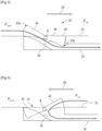
- the scoop 30 here has a general V-shape in cross section and comprises two concave curved aerodynamic surfaces 52, 54, respectively upstream and downstream, which define the capture mouths 30a, 30b of the scoop.
- the body 40 comprises a lower end 40a (or inner end with respect to the axis A) which is relatively thin in the axial direction and which is capable of sliding on the wall 32, and an upper end 40b which is thicker in the axial direction and which is able to slide on another wall 56 mounted on or around the wall 32. It is therefore understood that the scoop is sandwiched between the walls 32 and 56.
- the scoop 30 is configured to automatically adopt a position illustrated in the figure 7 when it is swept by the secondary flow 28.
- the dynamic pressure Pamont is then higher than the dynamic pressure Paval.
- the capture mouth 30a and in particular the surface 52 captures and guides a part of the secondary flow 28 towards the conduit 34.
- the lower end 40a of the body 40 of the scoop 30 is located just downstream of the inlet orifice of the conduit 34 and resting on the wall 32.
- the scoop 30 is also configured to automatically adopt a position illustrated in the figure 8 when it is swept by the secondary flow 28'.
- the dynamic pressure Pamont is then lower than the dynamic pressure Paval.
- the capture mouth 30b and in particular the surface 54 captures and guides a part of the secondary flow 28' towards the conduit 34.
- the lower end 40a of the body 40 of the scoop 30 is located just upstream of the inlet orifice of the conduit 38 (with reference to the air flow in normal operation) and resting on the wall 32.
- the scoop 30 could include a magnet or spring device that would be configured to hold the body in at least one of the two aforementioned positions, and thus prevent any oscillation about this position in operation.
- the body would for example be held in each of the positions of the Figures 5 and 6 by a magnet or a spring, the holding force of which would be overcome as soon as the air flow disappears or is reversed.
- the body could also be urged by this type of device, in the absence of any flow, into an intermediate position of closing the inlet orifice of the conduit 34.
- turbomachine equipped with a nacelle and structural arms for connecting the gas generator to the nacelle
- the invention is not limited to this type of turbomachine and applies for example also to a turbomachine with an unshrouded propeller.
Landscapes
- Engineering & Computer Science (AREA)
- Chemical & Material Sciences (AREA)
- Combustion & Propulsion (AREA)
- Mechanical Engineering (AREA)
- General Engineering & Computer Science (AREA)
- Physics & Mathematics (AREA)
- Geometry (AREA)
- Aviation & Aerospace Engineering (AREA)
- Structures Of Non-Positive Displacement Pumps (AREA)
Description
- La présente invention concerne une écope pour une turbomachine d'aéronef, ainsi qu'une turbomachine comportant une telle écope.
- L'arrière-plan technique comprend notamment les documents
US-A1-2009/152406 ,WO-A2-2005/016748 ,US-A-3,109,610 etFR-A1-3 028 289 - Une écope est ainsi un dispositif qui permet de capter une partie d'un flux d'air en écoulement. En général, une écope fait saillie sur une surface ou une paroi balayée par un flux d'air et cette écope capte une partie de ce flux d'air pour l'acheminer jusqu'à l'équipement à alimenter. Cet équipement est par exemple un échangeur de chaleur, l'air prélevé servant ainsi à alimenter un circuit d'air froid de l'échangeur.
- Lorsque la turbomachine est un turboréacteur à double flux, la turbomachine comprend une veine primaire d'écoulement d'un flux d'air primaire à l'intérieur d'un générateur de gaz, et une veine d'écoulement d'un flux secondaire autour du générateur de gaz et à l'intérieur d'une nacelle qui s'étend autour du générateur de gaz et d'une soufflante située en amont du générateur de gaz.
- Une écope peut être située sur une paroi annulaire externe d'une nacelle de la turbomachine, en vue de capter une partie du flux d'air s'écoulant autour de la nacelle en fonctionnement. Une écope peut également être située sur une paroi annulaire entourant le générateur de gaz, en vue de capter une partie du flux d'air secondaire.
- Dans la technique actuelle, il existe deux technologies d'écope. Selon une première technologie, l'écope comprend un corps de captation qui est fixe. L'avantage de ce type d'écope est qu'elle est simple à concevoir et à entretenir. Un inconvénient de cette écope est qu'elle crée un obstacle dans l'écoulement d'air et entraîne des perturbations et des pertes de charge dans cet écoulement même lorsqu'un prélèvement d'air par l'écope n'est pas nécessaire.
- Selon une autre technologie, l'écope comprend un corps de captation qui est mobile depuis une position fermée ou rabattue dans laquelle le corps ne forme pas un obstacle à l'écoulement d'air, et une position ouverte ou déployée dans laquelle le corps s'étend dans le flux d'air pour en capter une partie. Le déplacement du corps est alors assuré par un actionneur et contrôlé de manière active par un organe de commande dédié.
- L'avantage de cette écope est lié au fait qu'elle ne crée pas d'obstacle et génère donc peu de pertes de charge dans l'écoulement d'air lorsqu'elle n'est pas utilisée, mais son inconvénient est qu'elle est complexe à réaliser et donc coûteuse, et demande en outre des opérations de maintenance régulière.
- La présente invention propose une solution à au moins une partie des inconvénients de ces technologies antérieures.
- La présente invention concerne une écope pour une turbomachine d'aéronef, cette écope comportant un corps qui est mobile entre au moins deux positions dont une première position dans laquelle il est configuré pour capter une partie d'un premier flux d'air s'écoulant dans une première direction, et une deuxième position dans laquelle il est configuré pour capter une partie d'un second flux d'air s'écoulant dans une deuxième direction qui est opposée à la première direction, où ledit corps est monté libre en déplacement entre lesdites au moins deux positions de façon à adopter automatiquement la première position lors de l'écoulement du premier flux d'air, et à adopter automatiquement la deuxième position lors de la l'écoulement du deuxième flux d'air.
- L'écope selon l'invention a un fonctionnement autonome ou passif, c'est-à-dire qu'elle se déplace et adopte une position sans intervention particulière, c'est-à-dire sans actionnement mécanique ou contrôle particulier.
- L'écope selon l'invention peut en outre être assimilée à une double écope dans la mesure où elle est configurée pour capter de l'air provenant de deux directions opposées et donc différentes.
- Dans le cas particulier précité où l'écope serait montée sur une paroi entourant un générateur de gaz et définissant intérieurement une veine secondaire, on comprend qu'une partie d'un flux d'air s'écoulant dans la première direction, depuis la soufflante jusqu'à une tuyère d'échappement des gaz de la turbomachine (qui correspond au fonctionnement normal de la turbomachine), serait captée par l'écope dans sa première position, et qu'une partie d'un flux d'air s'écoulant dans la seconde direction, depuis la tuyère jusqu'à la soufflante (qui correspond à un fonctionnement d'inversion de poussée de la turbomachine), serait captée par l'écope dans sa seconde position.
- Le déplacement du corps de l'écope entre ses positions est automatique et dépend de la direction d'écoulement du flux d'air au niveau de ce corps, et plus particulièrement de l'effet de captation du flux d'air qui a tendance à déplacer l'écope dans l'une de ses positions. Autrement dit, c'est une différence de pression dynamique d'un côté et de l'autre de l'écope (entre l'amont et l'aval de l'écope en fonctionnement normal de la turbomachine) qui provoque ce déplacement. Lorsqu'un flux d'air s'écoule dans la première direction, l'effet de pression dynamique en amont de l'écope provoque le déplacement de l'écope dans sa première position de manière automatique. Lorsqu'un flux d'air s'écoule dans la deuxième direction, l'effet de pression dynamique en amont de l'écope (en fonctionnement normal de la turbomachine) provoque le déplacement de l'écope dans sa deuxième position de manière automatique.
- L'écope selon l'invention peut comprendre une ou plusieurs des caractéristiques suivantes, prises isolément les unes des autres, ou en combinaison les unes avec les autres :
- ledit corps est mobile en pivotement ou en coulissement entre lesdites positions ;
- ledit corps est mobile en pivotement autour d'un axe sensiblement perpendiculaire auxdites première et deuxième directions ;
- ledit corps est configuré pour adopter une position intermédiaire de repos, situé entre les première et deuxième positions, en l'absence d'écoulement du premier flux d'air et du deuxième flux d'air ; lorsqu'aucun flux d'air s'écoule au niveau de l'écope, il n'y a pas d'effet de captation ni de pression dynamique et le corps de l'écope adopte automatiquement cette position intermédiaire ;
- l'écope comprend un orifice de passage d'air capté par le corps, ledit corps étant configuré pour fermer cet orifice lorsqu'il est dans la position intermédiaire et pour l'ouvrir lorsqu'il est dans chacune des première et deuxième positions ;
- ledit corps comprend une première bouche ou surface aérodynamique de captation orientée vers la deuxième direction, et une seconde bouche ou surface aérodynamique de captation orientée vers la première direction ;
- les première et seconde surfaces aérodynamiques sont planes ou incurvées concaves ;
- ledit corps a une forme générale de dièdre ou en section transversale une forme générale en V ;
- -- l'écope comprend un dispositif à aimant ou ressort, configuré pour maintenir le corps dans au moins l'une de ses positions.
- La présente invention concerne également une turbomachine, en particulier d'aéronef, comportant au moins une écope telle que décrite ci-dessus.
- La turbomachine selon l'invention peut comprendre une ou plusieurs des caractéristiques suivantes, prises isolément les unes des autres, ou en combinaison les unes avec les autres :
- la turbomachine est du type à double flux et comprend une veine primaire d'écoulement d'un flux primaire à l'intérieur d'un générateur de gaz, et une veine secondaire d'écoulement d'un flux secondaire autour du générateur de gaz, l'écope étant située sur une paroi annulaire entourant le générateur de gaz et définissant intérieurement la veine secondaire ;
- l'écope est située à une entrée d'un conduit d'amenée d'air jusqu'à un échangeur de chaleur, par exemple air/huile ;
- la turbomachine est dépourvue d'inverseur de poussée et comprend une soufflante dont les aubes sont à calage variable et sont aptes à adopter une première position de calage permettant l'écoulement du premier flux d'air sur la paroi, et une seconde position de calage permettant l'écoulement du second flux d'air sur la paroi.
- D'autres caractéristiques et avantages ressortiront de la description qui suit d'un mode de réalisation non limitatif de l'invention en référence aux dessins annexés sur lesquels :
- [
Fig.1 ] lafigure 1 est une demi vue schématique en coupe axiale d'une turbomachine équipée d'une écope selon l'invention, cette écope étant dans une première position, - [
Fig.2 ] lafigure 2 est une demi vue schématique en coupe axiale de la turbomachine de lafigure 1 , l'écope étant dans une deuxième position, - [
Fig.3 ] lafigure 3 est une vue schématique en perspective d'un mode de réalisation d'une écope selon l'invention, - [
Fig.4 ] lafigure 4 est une vue schématique à plus grande échelle d'une partie d'une turbomachine équipée de l'écope de lafigure 3 , qui est ici dans une position intermédiaire de repos, - [
Fig.5 ] lafigure 5 est une vue similaire à celle de lafigure 4 et montrant l'écope dans sa première position, - [
Fig.6 ] lafigure 6 est une vue similaire à celle de lafigure 4 et montrant l'écope dans sa deuxième position, - [
Fig.7 ] lafigure 7 est une vue schématique à plus grande échelle d'une partie d'une turbomachine équipée d'une variante de réalisation d'une écope selon l'invention, qui est ici dans une première position, et - [
Fig.8 ] lafigure 8 est une vue similaire à celle de lafigure 7 et montrant l'écope dans sa deuxième position. - Les
figures 1 et 2 représentent une turbomachine 10 d'aéronef et en particulier un turboréacteur à double flux. - La turbomachine 10 comprend un générateur de gaz 12 comportant, d'amont en aval par rapport au sens de circulation des gaz selon un fonctionnement normal illustré à la
figure 1 (cf. flèches), au moins un compresseur 13, une chambre de combustion 14 et au moins une turbine 16. Le générateur de gaz 12 définit une veine annulaire 18 d'écoulement d'un flux primaire 20 qui s'écoule dans le compresseur 13 puis est mélangé à du carburant et brûlé dans la chambre de combustion 14, pour être afin détendu dans la turbine 16. - Une soufflante 22 est montée à une extrémité axiale du générateur de gaz 12, à l'amont dans l'exemple représenté et par référence à la circulation des gaz selon le fonctionnement normal de la
figure 1 , et comprend une hélice entraînée en rotation par le rotor du compresseur et de la turbine. Dans le cas d'un générateur de gaz 12 à double corps, respectivement à basse pression et à haute pression, la soufflante 22 serait entraînée en rotation par un arbre du corps basse pression. - La soufflante 22 et au moins une partie du générateur de gaz 12 sont entourées par une nacelle 24 qui définit autour du générateur de gaz 12 une veine annulaire 26 d'écoulement d'un flux secondaire 28. La nacelle 24 est reliée au générateur de gaz 12 par des bras structuraux 29 qui s'étendent sensiblement radialement entre le générateur de gaz et la nacelle par référence à l'axe longitudinal A de la turbomachine qui correspond à l'axe de rotation principal de son ou ses rotors et en particulier du corps basse pression précité.
- Le flux d'air entrant dans la turbomachine (flèche F1) pénètre dans la nacelle 24 et traverse la soufflante 22, et se divise ensuite en deux flux annulaires et coaxiaux, le flux annulaire externe qui correspond au flux secondaire 28 précité, et le flux annulaire interne qui correspond au flux primaire 20.
- Comme évoqué ci-dessus, la
figure 1 représente le mode de fonctionnement normal de la turbomachine 10 dans lequel le flux secondaire 28 s'écoule de l'amont vers l'aval de la turbomachine 10 et donc de la gauche vers la droite du dessin. - La
figure 2 représente un mode de fonctionnement à flux inversé dans lequel le flux secondaire 28' s'écoule de l'aval vers l'amont et donc de la droite vers la gauche du dessin. - Cette inversion du sens d'écoulement du flux secondaire 28' peut être réalisée grâce à un inverseur de poussée situé à l'aval de la nacelle 24. De manière préférée, dans le cadre de la présente invention, cette inversion est réalisée par la soufflante 22 elle-même, qui comprend des pales à calage variable aptes à adopter une position de calage dans laquelle elles inversent le sens de circulation des gaz dans la turbomachine. Cette technologie permet de ne pas équiper la turbomachine d'un inverseur de poussée et donc de simplifier la nacelle en la raccourcissant par exemple, comme dans l'exemple représenté.
- La présente invention propose une écope 30 qui est apte à capter de l'air quelle que soit la direction d'écoulement de cet air parmi deux directions opposées. L'écope 30 selon l'invention peut ainsi être assimilée à une double écope.
- Les
figures 1 et 2 illustrent un exemple d'implantation d'une écope 30 dans la turbomachine 10. L'écope 30 est ici installée sur une paroi annulaire externe 32 du générateur de gaz 12 qui définit intérieurement la veine 26 d'écoulement du flux secondaire 28, 28'. - En variante, l'écope 30 pourrait être montée sur une paroi annulaire qui définirait extérieurement la veine 26, tel qu'une paroi de la nacelle 24 par exemple. L'écope 30 peut être montée dans n'importe quelle position axiale le long de l'axe A.
- L'écope 30 est montée à une extrémité d'un conduit 34 d'acheminement d'air jusqu'à un échangeur de chaleur 36, du type air/huile par exemple. Cette extrémité forme un orifice d'entrée d'air dans le conduit.
- L'extrémité du conduit 34, opposée à l'écope 30, débouche par exemple sur une tuyère 38 d'échappement des gaz de la turbomachine 10. L'échangeur 36 est ici situé sensiblement au milieu du conduit 34.
- Selon l'invention, l'écope 30 comporte un corps 40 qui est mobile entre au moins deux positions dont :
- une première position illustrée à la
figure 1 dans laquelle il est configuré pour capter une partie d'un premier flux d'air s'écoulant dans une première direction, tel que le flux secondaire 28, et - une deuxième position illustrée à la
figure 2 dans laquelle il est configuré pour capter une partie d'un second flux d'air s'écoulant dans une deuxième direction qui est opposée à la première direction, tel que le flux secondaire inversé 28'. - Le corps 40 est monté libre en déplacement entre ces positions précitées de façon à adopter automatiquement la première position lors de l'écoulement du premier flux d'air, et à adopter automatiquement la deuxième position lors de la l'écoulement du deuxième flux d'air.
- Les
figures 3 à 6 illustrent un premier mode de réalisation de l'écope 30 et lesfigures 7 et 8 illustrent un second mode de réalisation de cette écope. - L'écope 30 de la
figure 3 comprend un corps 40 qui est mobile en pivotement autour d'un axe B sensiblement perpendiculaire aux deux directions précitées. - L'écope 30 a ici une forme générale de dièdre et comprend deux bouches de captation 30a, 30b. Un premier côté du dièdre comprend une paroi 42 de forme générale rectangulaire. Un bord 42a de cette paroi 42 est situé au niveau de l'axe B et deux bords opposés 42b de cette paroi 42, qui sont sensiblement perpendiculaires à l'axe B, sont reliés à des rebords 44 qui sont parallèles et en regard l'un de l'autre. Le bord 42c de la paroi opposé au bord 42a définit une première bouche de captation 30a avec des bords adjacents des rebords 44.
- Un second côté du dièdre comprend une paroi 46 de forme générale rectangulaire. Un bord 46a de cette paroi 46 est situé au niveau de l'axe B et jointif au bord 42a de la paroi 42. Deux bords opposés 46b de la paroi 46, qui sont sensiblement perpendiculaires à l'axe B, sont reliés à des rebords 48 qui sont parallèles et en regard l'un de l'autre. Le bord 46c de la paroi opposé au bord 46a définit la deuxième bouche de captation 30b avec des bords adjacents des rebords 48.
- L'écope 30 de la
figure 3 peut adopter de manière automatique au moins trois positions illustrées respectivement auxfigures 4 à 6 . - L'écope 30 est tout d'abord configurée pour adopter une position intermédiaire de repos illustrée à la
figure 4 , en l'absence d'écoulement autour de cette écope et sur la paroi 32. Cette position est adoptée de manière automatique par le fait que les pressions situées juste en amont et en aval de l'écope (respectivement Pamont et Pavai), c'est-à-dire au niveau des deux bouches de captation 30a, 30b, sont identiques. Dans ce cas, le corps de l'écope peut fermer, de manière hermétique ou non, l'orifice d'entrée du conduit 34. - L'écope 30 est également configurée pour adopter automatiquement une position illustrée à la
figure 5 lorsqu'elle est balayée par le flux secondaire 28. La pression dynamique en amont de l'écope (Pamont) est alors supérieure à la pression dynamique en aval de l'écope (Paval). La bouche de captation 30a est ouverte et la bouche de captation 30b est fermée. Une partie du flux secondaire 28 est alors captée par l'écope 30 et pénètre dans le conduit 34 qui peut comprendre au niveau de l'orifice d'entrée une surface aérodynamique 50 d'optimisation d'écoulement d'air afin d'éviter les décollements. - Dans cette position, la paroi 46 s'étend de préférence dans le prolongement de la paroi 32, comme cela est visible à la
figure 5 . - L'écope 30 est également configurée pour adopter automatiquement une position illustrée à la
figure 6 lorsqu'elle est balayée par le flux secondaire 28'. La pression dynamique Pamont est alors inférieure à la pression dynamique Paval. La bouche de captation 30b est ouverte et la bouche de captation 30a est fermée. Une partie du flux secondaire 28' est alors captée par l'écope 30 et pénètre dans le conduit 34. Dans cette position, la paroi 42 s'étend de préférence dans le prolongement de la paroi 32, comme cela est visible à lafigure 6 . - Bien que cela ne soit pas représenté, l'écope 30 pourrait comprendre un dispositif à aimant ou ressort qui serait configuré pour maintenir le corps dans au moins une des trois positions précitées, et éviter ainsi toute oscillation autour de cette position en fonctionnement. Le corps serait par exemple maintenu dans la position de la
figure 4 par un aimant ou un ressort, dont la force de maintien serait vaincue dès l'écoulement du flux secondaire 28 ou 28'. Le corps serait par exemple maintenu dans chacune des positions desfigures 5 et 6 par un aimant ou un ressort, dont la force de maintien serait vaincue dès la disparition ou l'inversion de l'écoulement d'air. - L'écope 30 des
figures 7 et 8 comprend un corps 40 qui est mobile en translation le long d'un axe parallèle à l'axe A précité. - L'écope 30 a ici en section transversale une forme générale en V et comprend deux surfaces aérodynamiques 52, 54 incurvées concaves, respectivement amont et aval, qui définissent les bouches de captation 30a, 30b de l'écope.
- Le corps 40 comprend une extrémité inférieure 40a (ou intérieure vis-à-vis de l'axe A) qui est relativement mince en direction axiale et qui est apte à coulisser sur la paroi 32, et une extrémité supérieure 40b qui est plus épaisse en direction axiale et qui est apte à coulisser sur une autre paroi 56 montée sur ou autour de la paroi 32. On comprend donc que l'écope est prise en sandwich entre les parois 32 et 56.
- L'écope 30 est configurée pour adopter automatiquement une position illustrée à la
figure 7 lorsqu'elle est balayée par le flux secondaire 28. La pression dynamique Pamont est alors supérieure à la pression dynamique Paval. La bouche de captation 30a et en particulier la surface 52 capte et guide une partie du flux secondaire 28 vers le conduit 34. - Dans cette position, l'extrémité inférieure 40a du corps 40 de l'écope 30 est située juste en aval de l'orifice d'entrée du conduit 34 et en appui sur la paroi 32.
- L'écope 30 est également configurée pour adopter automatiquement une position illustrée à la
figure 8 lorsqu'elle est balayée par le flux secondaire 28'. La pression dynamique Pamont est alors inférieure à la pression dynamique Paval. La bouche de captation 30b et en particulier la surface 54 capte et guide une partie du flux secondaire 28' vers le conduit 34. - Dans cette position, l'extrémité inférieure 40a du corps 40 de l'écope 30 est située juste en amont de l'orifice d'entrée du conduit 38 (par référence à l'écoulement d'air en fonctionnement normal) et en appui sur la paroi 32.
- Bien que cela ne soit pas représenté, l'écope 30 pourrait comprendre un dispositif à aimant ou ressort qui serait configuré pour maintenir le corps dans au moins une des deux positions précitées, et éviter ainsi toute oscillation autour de cette position en fonctionnement. Le corps serait par exemple maintenu dans chacune des positions des
figures 5 et 6 par un aimant ou un ressort, dont la force de maintien serait vaincue dès la disparition ou l'inversion de l'écoulement d'air. Le corps pourrait également être sollicité par ce type de dispositif, en l'absence de tout écoulement, dans une position intermédiaire de fermeture de l'orifice d'entrée du conduit 34. - Bien que l'invention ait été décrite et illustrée dans le contexte d'une turbomachine carénée, équipée d'une nacelle et de bras structuraux de liaison du générateur de gaz à la nacelle, l'invention n'est pas limitée à ce type de turbomachine et s'applique par exemple également à une turbomachine à hélice non carénée.
Claims (12)
- Ecope (30) pour une turbomachine (10) d'aéronef, cette écope comportant un corps (40) qui est mobile entre au moins deux positions dont une première position dans laquelle il est configuré pour capter une partie d'un premier flux d'air (28) s'écoulant dans une première direction, et une deuxième position dans laquelle il est configuré pour capter une partie d'un second flux d'air (28') s'écoulant dans une deuxième direction qui est opposée à la première direction, caractérisée en ce que ledit corps est monté libre en déplacement entre lesdites au moins deux positions de façon à adopter automatiquement la première position lors de l'écoulement du premier flux d'air, et à adopter automatiquement la deuxième position lors de la l'écoulement du deuxième flux d'air.
- Ecope (30) selon la revendication précédente, dans laquelle ledit corps (40) est mobile en pivotement ou en coulissement entre lesdites positions.
- Ecope (30) selon la revendication précédente, dans laquelle ledit corps (40) est mobile en pivotement autour d'un axe (B) sensiblement perpendiculaire auxdites première et deuxième directions.
- Ecope (30) selon l'une des revendications précédentes, dans laquelle ledit corps (40) est configuré pour adopter une position intermédiaire de repos, situé entre les première et deuxième positions, en l'absence d'écoulement du premier flux d'air et du deuxième flux d'air (28, 28').
- Ecope (30) selon la revendication précédente, dans laquelle elle comprend un orifice de passage d'air capté par le corps (40), ledit corps étant configuré pour fermer cet orifice lorsqu'il est dans la position intermédiaire et pour l'ouvrir lorsqu'il est dans chacune des première et deuxième positions.
- Ecope (30) selon l'une des revendications précédentes, dans laquelle ledit corps (40) comprend une première bouche (30a) ou surface aérodynamique (52) de captation orientée vers la deuxième direction, et une seconde bouche (30b) ou surface aérodynamique (54) de captation orientée vers la première direction.
- Ecope (30) selon la revendication précédente, dans laquelle les première et seconde surfaces aérodynamiques (52, 54) sont planes ou incurvées concaves.
- Ecope (30) selon l'une des revendications précédentes, dans laquelle ledit corps (40) a une forme générale de dièdre ou en section transversale une forme générale en V.
- Turbomachine (10), en particulier d'aéronef, comportant au moins une écope (30) selon l'une des revendications précédentes.
- Turbomachine (10) selon la revendication précédente, dans laquelle elle est du type à double flux et comprend une veine primaire (18) d'écoulement d'un flux primaire (20) à l'intérieur d'un générateur de gaz (12), et une veine secondaire (26) d'écoulement d'un flux secondaire (28) autour du générateur de gaz, l'écope étant située sur une paroi annulaire (32) entourant le générateur de gaz et définissant intérieurement la veine secondaire.
- Turbomachine (10) selon la revendication précédente, dans laquelle l'écope (30) est située à une entrée d'un conduit (34) d'amenée d'air jusqu'à un échangeur de chaleur (36), par exemple air/huile.
- Turbomachine (10) selon la revendication précédente, dans laquelle elle est dépourvue d'inverseur de poussée et comprend une soufflante (22) dont les aubes sont à calage variable et sont aptes à adopter une première position de calage permettant l'écoulement du premier flux d'air sur la paroi, et une seconde position de calage permettant l'écoulement du second flux d'air sur la paroi.
Applications Claiming Priority (2)
| Application Number | Priority Date | Filing Date | Title |
|---|---|---|---|
| FR2012588A FR3117149B1 (fr) | 2020-12-03 | 2020-12-03 | Ecope pour une turbomachine d’aeronef |
| PCT/FR2021/052087 WO2022117934A1 (fr) | 2020-12-03 | 2021-11-24 | Ecope pour une turbomachine d'aeronef |
Publications (2)
| Publication Number | Publication Date |
|---|---|
| EP4256187A1 EP4256187A1 (fr) | 2023-10-11 |
| EP4256187B1 true EP4256187B1 (fr) | 2024-09-18 |
Family
ID=74758967
Family Applications (1)
| Application Number | Title | Priority Date | Filing Date |
|---|---|---|---|
| EP21823984.6A Active EP4256187B1 (fr) | 2020-12-03 | 2021-11-24 | Ecope pour une turbomachine d'aeronef |
Country Status (5)
| Country | Link |
|---|---|
| US (1) | US12116930B2 (fr) |
| EP (1) | EP4256187B1 (fr) |
| CN (1) | CN116601077A (fr) |
| FR (1) | FR3117149B1 (fr) |
| WO (1) | WO2022117934A1 (fr) |
Families Citing this family (1)
| Publication number | Priority date | Publication date | Assignee | Title |
|---|---|---|---|---|
| FR3147254A1 (fr) * | 2023-03-31 | 2024-10-04 | Airbus Operations (S.A.S.) | Ensemble de propulsion comprenant au moins un dispositif de ventilation régulé, aéronef comprenant au moins un tel ensemble de propulsion |
Family Cites Families (10)
| Publication number | Priority date | Publication date | Assignee | Title |
|---|---|---|---|---|
| US3228653A (en) * | 1962-08-15 | 1966-01-11 | Lea G Trimmer | Butterfly valve device having particular seal and split-body structure |
| US3109610A (en) * | 1962-09-12 | 1963-11-05 | Boeing Co | Combined aircraft air intake scoop, foreign material ingestion inhibitor, and aerodynamic flap |
| US4926633A (en) * | 1989-06-27 | 1990-05-22 | The United States Of America As Represented By The Secretary Of The Air Force | Coolant pressure regulating apparatus |
| US5269135A (en) * | 1991-10-28 | 1993-12-14 | General Electric Company | Gas turbine engine fan cooled heat exchanger |
| US7014144B2 (en) * | 2003-07-22 | 2006-03-21 | Honeywell International, Inc. | Dual action inlet door and method for use thereof |
| US8096498B2 (en) * | 2007-12-12 | 2012-01-17 | Hamilton Sundstrand Corporation | Rotating auxiliary power unit air inlet door |
| US9243563B2 (en) * | 2012-01-25 | 2016-01-26 | Honeywell International Inc. | Gas turbine engine in-board cooled cooling air system |
| US9206912B2 (en) * | 2013-01-23 | 2015-12-08 | The Boeing Company | Dual door fan air modulating valve |
| FR3028289B1 (fr) * | 2014-11-06 | 2019-12-27 | Airbus Operations (S.A.S.) | Turbomachine d'aeronef comprenant un boitier d'admission d'air a profil aerodynamique variable |
| FR3039216B1 (fr) * | 2015-07-22 | 2019-12-20 | Safran Aircraft Engines | Ensemble propulsif pour aeronef comportant un inverseur de poussee |
-
2020
- 2020-12-03 FR FR2012588A patent/FR3117149B1/fr active Active
-
2021
- 2021-11-24 EP EP21823984.6A patent/EP4256187B1/fr active Active
- 2021-11-24 CN CN202180081413.5A patent/CN116601077A/zh active Pending
- 2021-11-24 WO PCT/FR2021/052087 patent/WO2022117934A1/fr not_active Ceased
- 2021-11-24 US US18/254,775 patent/US12116930B2/en active Active
Also Published As
| Publication number | Publication date |
|---|---|
| US20230417181A1 (en) | 2023-12-28 |
| WO2022117934A1 (fr) | 2022-06-09 |
| EP4256187A1 (fr) | 2023-10-11 |
| CN116601077A (zh) | 2023-08-15 |
| US12116930B2 (en) | 2024-10-15 |
| FR3117149B1 (fr) | 2022-10-21 |
| FR3117149A1 (fr) | 2022-06-10 |
Similar Documents
| Publication | Publication Date | Title |
|---|---|---|
| EP1865184B1 (fr) | Turbomachine avec un système de décharge d'un compresseur a basse pression. | |
| EP2801707B1 (fr) | Circuit de lubrification de turbomachine avec vanne anti-siphon pour windmilling | |
| EP1884649B1 (fr) | Turbomachine à double flux à variation de sa section de col par moyens d'injection d'air | |
| EP3204620B1 (fr) | Stator de turbomachine d'aéronef | |
| FR3057620A1 (fr) | Ensemble propulsif comprenant un conduit d'alimentation du generateur de gaz dans un carter inter-veine | |
| EP2288813B1 (fr) | Injection d'air dans la veine d'un compresseur de turbomachine | |
| EP1956226B1 (fr) | Dispositif de décharge pour un turboréacteur, et turboréacteur le comportant | |
| EP4022174B1 (fr) | Turbomachine a double flux pour un aeronef | |
| EP3247885B1 (fr) | Système de commande d'aubes à calage variable pour une turbomachine | |
| EP0589745B1 (fr) | Système de réglage d'alimentation d'une turbomachine | |
| EP4256187B1 (fr) | Ecope pour une turbomachine d'aeronef | |
| FR2676780A1 (fr) | Inverseur de poussee pour turbosoufflante a tres grand taux dilution. | |
| EP3963202B1 (fr) | Structure de confluence d'une veine primaire et d'une veine secondaire dans une turbomachine a double flux | |
| EP4288650B1 (fr) | Dispositif d'étanchéité pour vanne de décharge d'une turbomachine | |
| FR3094045A1 (fr) | Turbomachine comprenant une conduite de contournement pour des fluides de nettoyage | |
| WO2022263753A1 (fr) | Systeme de changement de pas des pales d'une helice d'une turbomachine | |
| FR3093136A1 (fr) | Carter d’entree pour une turbomachine d’aeronef | |
| FR3079875A1 (fr) | Dispositif de decharge de turbomachine comportant une vanne | |
| FR2907853A1 (fr) | Tuyere d'ejection des gaz pour turbomachine a double flux ayant une section d'ejection ou de col variable par deploiement de creneaux | |
| WO2024084150A1 (fr) | Turbomachine a cycle recupere equipee d'un echangeur de chaleur | |
| FR3155262A1 (fr) | Tuyere de soufflante double flux a section variable ultra compacte | |
| FR2976624A1 (fr) | Turbomoteur a double flux pour aeronef, a section de sortie variable du flux secondaire | |
| FR3125505A1 (fr) | Systeme de changement de pas des pales d’une helice d’une turbomachine |
Legal Events
| Date | Code | Title | Description |
|---|---|---|---|
| STAA | Information on the status of an ep patent application or granted ep patent |
Free format text: STATUS: UNKNOWN |
|
| STAA | Information on the status of an ep patent application or granted ep patent |
Free format text: STATUS: THE INTERNATIONAL PUBLICATION HAS BEEN MADE |
|
| PUAI | Public reference made under article 153(3) epc to a published international application that has entered the european phase |
Free format text: ORIGINAL CODE: 0009012 |
|
| STAA | Information on the status of an ep patent application or granted ep patent |
Free format text: STATUS: REQUEST FOR EXAMINATION WAS MADE |
|
| 17P | Request for examination filed |
Effective date: 20230607 |
|
| AK | Designated contracting states |
Kind code of ref document: A1 Designated state(s): AL AT BE BG CH CY CZ DE DK EE ES FI FR GB GR HR HU IE IS IT LI LT LU LV MC MK MT NL NO PL PT RO RS SE SI SK SM TR |
|
| DAV | Request for validation of the european patent (deleted) | ||
| DAX | Request for extension of the european patent (deleted) | ||
| GRAP | Despatch of communication of intention to grant a patent |
Free format text: ORIGINAL CODE: EPIDOSNIGR1 |
|
| STAA | Information on the status of an ep patent application or granted ep patent |
Free format text: STATUS: GRANT OF PATENT IS INTENDED |
|
| INTG | Intention to grant announced |
Effective date: 20240624 |
|
| GRAS | Grant fee paid |
Free format text: ORIGINAL CODE: EPIDOSNIGR3 |
|
| GRAA | (expected) grant |
Free format text: ORIGINAL CODE: 0009210 |
|
| STAA | Information on the status of an ep patent application or granted ep patent |
Free format text: STATUS: THE PATENT HAS BEEN GRANTED |
|
| AK | Designated contracting states |
Kind code of ref document: B1 Designated state(s): AL AT BE BG CH CY CZ DE DK EE ES FI FR GB GR HR HU IE IS IT LI LT LU LV MC MK MT NL NO PL PT RO RS SE SI SK SM TR |
|
| REG | Reference to a national code |
Ref country code: GB Ref legal event code: FG4D Free format text: NOT ENGLISH |
|
| REG | Reference to a national code |
Ref country code: CH Ref legal event code: EP |
|
| REG | Reference to a national code |
Ref country code: IE Ref legal event code: FG4D Free format text: LANGUAGE OF EP DOCUMENT: FRENCH |
|
| REG | Reference to a national code |
Ref country code: DE Ref legal event code: R096 Ref document number: 602021019088 Country of ref document: DE |
|
| REG | Reference to a national code |
Ref country code: LT Ref legal event code: MG9D |
|
| PG25 | Lapsed in a contracting state [announced via postgrant information from national office to epo] |
Ref country code: NO Free format text: LAPSE BECAUSE OF FAILURE TO SUBMIT A TRANSLATION OF THE DESCRIPTION OR TO PAY THE FEE WITHIN THE PRESCRIBED TIME-LIMIT Effective date: 20241218 |
|
| PG25 | Lapsed in a contracting state [announced via postgrant information from national office to epo] |
Ref country code: GR Free format text: LAPSE BECAUSE OF FAILURE TO SUBMIT A TRANSLATION OF THE DESCRIPTION OR TO PAY THE FEE WITHIN THE PRESCRIBED TIME-LIMIT Effective date: 20241219 Ref country code: FI Free format text: LAPSE BECAUSE OF FAILURE TO SUBMIT A TRANSLATION OF THE DESCRIPTION OR TO PAY THE FEE WITHIN THE PRESCRIBED TIME-LIMIT Effective date: 20240918 |
|
| PG25 | Lapsed in a contracting state [announced via postgrant information from national office to epo] |
Ref country code: BG Free format text: LAPSE BECAUSE OF FAILURE TO SUBMIT A TRANSLATION OF THE DESCRIPTION OR TO PAY THE FEE WITHIN THE PRESCRIBED TIME-LIMIT Effective date: 20240918 |
|
| PG25 | Lapsed in a contracting state [announced via postgrant information from national office to epo] |
Ref country code: LV Free format text: LAPSE BECAUSE OF FAILURE TO SUBMIT A TRANSLATION OF THE DESCRIPTION OR TO PAY THE FEE WITHIN THE PRESCRIBED TIME-LIMIT Effective date: 20240918 |
|
| PG25 | Lapsed in a contracting state [announced via postgrant information from national office to epo] |
Ref country code: HR Free format text: LAPSE BECAUSE OF FAILURE TO SUBMIT A TRANSLATION OF THE DESCRIPTION OR TO PAY THE FEE WITHIN THE PRESCRIBED TIME-LIMIT Effective date: 20240918 |
|
| REG | Reference to a national code |
Ref country code: NL Ref legal event code: MP Effective date: 20240918 |
|
| PG25 | Lapsed in a contracting state [announced via postgrant information from national office to epo] |
Ref country code: RS Free format text: LAPSE BECAUSE OF FAILURE TO SUBMIT A TRANSLATION OF THE DESCRIPTION OR TO PAY THE FEE WITHIN THE PRESCRIBED TIME-LIMIT Effective date: 20241218 |
|
| PG25 | Lapsed in a contracting state [announced via postgrant information from national office to epo] |
Ref country code: RS Free format text: LAPSE BECAUSE OF FAILURE TO SUBMIT A TRANSLATION OF THE DESCRIPTION OR TO PAY THE FEE WITHIN THE PRESCRIBED TIME-LIMIT Effective date: 20241218 Ref country code: NO Free format text: LAPSE BECAUSE OF FAILURE TO SUBMIT A TRANSLATION OF THE DESCRIPTION OR TO PAY THE FEE WITHIN THE PRESCRIBED TIME-LIMIT Effective date: 20241218 Ref country code: LV Free format text: LAPSE BECAUSE OF FAILURE TO SUBMIT A TRANSLATION OF THE DESCRIPTION OR TO PAY THE FEE WITHIN THE PRESCRIBED TIME-LIMIT Effective date: 20240918 Ref country code: HR Free format text: LAPSE BECAUSE OF FAILURE TO SUBMIT A TRANSLATION OF THE DESCRIPTION OR TO PAY THE FEE WITHIN THE PRESCRIBED TIME-LIMIT Effective date: 20240918 Ref country code: GR Free format text: LAPSE BECAUSE OF FAILURE TO SUBMIT A TRANSLATION OF THE DESCRIPTION OR TO PAY THE FEE WITHIN THE PRESCRIBED TIME-LIMIT Effective date: 20241219 Ref country code: FI Free format text: LAPSE BECAUSE OF FAILURE TO SUBMIT A TRANSLATION OF THE DESCRIPTION OR TO PAY THE FEE WITHIN THE PRESCRIBED TIME-LIMIT Effective date: 20240918 Ref country code: BG Free format text: LAPSE BECAUSE OF FAILURE TO SUBMIT A TRANSLATION OF THE DESCRIPTION OR TO PAY THE FEE WITHIN THE PRESCRIBED TIME-LIMIT Effective date: 20240918 |
|
| REG | Reference to a national code |
Ref country code: AT Ref legal event code: MK05 Ref document number: 1724862 Country of ref document: AT Kind code of ref document: T Effective date: 20240918 |
|
| PG25 | Lapsed in a contracting state [announced via postgrant information from national office to epo] |
Ref country code: NL Free format text: LAPSE BECAUSE OF FAILURE TO SUBMIT A TRANSLATION OF THE DESCRIPTION OR TO PAY THE FEE WITHIN THE PRESCRIBED TIME-LIMIT Effective date: 20240918 |
|
| PG25 | Lapsed in a contracting state [announced via postgrant information from national office to epo] |
Ref country code: PT Free format text: LAPSE BECAUSE OF FAILURE TO SUBMIT A TRANSLATION OF THE DESCRIPTION OR TO PAY THE FEE WITHIN THE PRESCRIBED TIME-LIMIT Effective date: 20250120 Ref country code: IS Free format text: LAPSE BECAUSE OF FAILURE TO SUBMIT A TRANSLATION OF THE DESCRIPTION OR TO PAY THE FEE WITHIN THE PRESCRIBED TIME-LIMIT Effective date: 20250118 |
|
| PG25 | Lapsed in a contracting state [announced via postgrant information from national office to epo] |
Ref country code: RO Free format text: LAPSE BECAUSE OF FAILURE TO SUBMIT A TRANSLATION OF THE DESCRIPTION OR TO PAY THE FEE WITHIN THE PRESCRIBED TIME-LIMIT Effective date: 20240918 Ref country code: SM Free format text: LAPSE BECAUSE OF FAILURE TO SUBMIT A TRANSLATION OF THE DESCRIPTION OR TO PAY THE FEE WITHIN THE PRESCRIBED TIME-LIMIT Effective date: 20240918 |
|
| PG25 | Lapsed in a contracting state [announced via postgrant information from national office to epo] |
Ref country code: ES Free format text: LAPSE BECAUSE OF FAILURE TO SUBMIT A TRANSLATION OF THE DESCRIPTION OR TO PAY THE FEE WITHIN THE PRESCRIBED TIME-LIMIT Effective date: 20240918 |
|
| PG25 | Lapsed in a contracting state [announced via postgrant information from national office to epo] |
Ref country code: EE Free format text: LAPSE BECAUSE OF FAILURE TO SUBMIT A TRANSLATION OF THE DESCRIPTION OR TO PAY THE FEE WITHIN THE PRESCRIBED TIME-LIMIT Effective date: 20240918 Ref country code: AT Free format text: LAPSE BECAUSE OF FAILURE TO SUBMIT A TRANSLATION OF THE DESCRIPTION OR TO PAY THE FEE WITHIN THE PRESCRIBED TIME-LIMIT Effective date: 20240918 |
|
| PG25 | Lapsed in a contracting state [announced via postgrant information from national office to epo] |
Ref country code: CZ Free format text: LAPSE BECAUSE OF FAILURE TO SUBMIT A TRANSLATION OF THE DESCRIPTION OR TO PAY THE FEE WITHIN THE PRESCRIBED TIME-LIMIT Effective date: 20240918 Ref country code: PL Free format text: LAPSE BECAUSE OF FAILURE TO SUBMIT A TRANSLATION OF THE DESCRIPTION OR TO PAY THE FEE WITHIN THE PRESCRIBED TIME-LIMIT Effective date: 20240918 |
|
| PG25 | Lapsed in a contracting state [announced via postgrant information from national office to epo] |
Ref country code: SK Free format text: LAPSE BECAUSE OF FAILURE TO SUBMIT A TRANSLATION OF THE DESCRIPTION OR TO PAY THE FEE WITHIN THE PRESCRIBED TIME-LIMIT Effective date: 20240918 Ref country code: IT Free format text: LAPSE BECAUSE OF FAILURE TO SUBMIT A TRANSLATION OF THE DESCRIPTION OR TO PAY THE FEE WITHIN THE PRESCRIBED TIME-LIMIT Effective date: 20240918 |
|
| REG | Reference to a national code |
Ref country code: DE Ref legal event code: R097 Ref document number: 602021019088 Country of ref document: DE |
|
| REG | Reference to a national code |
Ref country code: CH Ref legal event code: PL |
|
| PG25 | Lapsed in a contracting state [announced via postgrant information from national office to epo] |
Ref country code: MC Free format text: LAPSE BECAUSE OF FAILURE TO SUBMIT A TRANSLATION OF THE DESCRIPTION OR TO PAY THE FEE WITHIN THE PRESCRIBED TIME-LIMIT Effective date: 20240918 |
|
| PG25 | Lapsed in a contracting state [announced via postgrant information from national office to epo] |
Ref country code: DK Free format text: LAPSE BECAUSE OF FAILURE TO SUBMIT A TRANSLATION OF THE DESCRIPTION OR TO PAY THE FEE WITHIN THE PRESCRIBED TIME-LIMIT Effective date: 20240918 |
|
| PG25 | Lapsed in a contracting state [announced via postgrant information from national office to epo] |
Ref country code: LU Free format text: LAPSE BECAUSE OF NON-PAYMENT OF DUE FEES Effective date: 20241124 |
|
| REG | Reference to a national code |
Ref country code: CH Ref legal event code: PL |
|
| PG25 | Lapsed in a contracting state [announced via postgrant information from national office to epo] |
Ref country code: CH Free format text: LAPSE BECAUSE OF NON-PAYMENT OF DUE FEES Effective date: 20241130 |
|
| PLBE | No opposition filed within time limit |
Free format text: ORIGINAL CODE: 0009261 |
|
| STAA | Information on the status of an ep patent application or granted ep patent |
Free format text: STATUS: NO OPPOSITION FILED WITHIN TIME LIMIT |
|
| 26N | No opposition filed |
Effective date: 20250619 |
|
| REG | Reference to a national code |
Ref country code: BE Ref legal event code: MM Effective date: 20241130 |
|
| PG25 | Lapsed in a contracting state [announced via postgrant information from national office to epo] |
Ref country code: SE Free format text: LAPSE BECAUSE OF FAILURE TO SUBMIT A TRANSLATION OF THE DESCRIPTION OR TO PAY THE FEE WITHIN THE PRESCRIBED TIME-LIMIT Effective date: 20240918 |
|
| PG25 | Lapsed in a contracting state [announced via postgrant information from national office to epo] |
Ref country code: BE Free format text: LAPSE BECAUSE OF NON-PAYMENT OF DUE FEES Effective date: 20241130 |
|
| PG25 | Lapsed in a contracting state [announced via postgrant information from national office to epo] |
Ref country code: IE Free format text: LAPSE BECAUSE OF NON-PAYMENT OF DUE FEES Effective date: 20241124 |
|
| PGFP | Annual fee paid to national office [announced via postgrant information from national office to epo] |
Ref country code: DE Payment date: 20251118 Year of fee payment: 5 |
|
| PGFP | Annual fee paid to national office [announced via postgrant information from national office to epo] |
Ref country code: GB Payment date: 20251125 Year of fee payment: 5 |
|
| PGFP | Annual fee paid to national office [announced via postgrant information from national office to epo] |
Ref country code: FR Payment date: 20251125 Year of fee payment: 5 |
|
| PG25 | Lapsed in a contracting state [announced via postgrant information from national office to epo] |
Ref country code: HU Free format text: LAPSE BECAUSE OF FAILURE TO SUBMIT A TRANSLATION OF THE DESCRIPTION OR TO PAY THE FEE WITHIN THE PRESCRIBED TIME-LIMIT; INVALID AB INITIO Effective date: 20211124 |
|
| PG25 | Lapsed in a contracting state [announced via postgrant information from national office to epo] |
Ref country code: CY Free format text: LAPSE BECAUSE OF FAILURE TO SUBMIT A TRANSLATION OF THE DESCRIPTION OR TO PAY THE FEE WITHIN THE PRESCRIBED TIME-LIMIT; INVALID AB INITIO Effective date: 20211124 |