EP4255775B1 - Automotive lamp optical system with light diffusive projection lens - Google Patents
Automotive lamp optical system with light diffusive projection lens Download PDFInfo
- Publication number
- EP4255775B1 EP4255775B1 EP21835596.4A EP21835596A EP4255775B1 EP 4255775 B1 EP4255775 B1 EP 4255775B1 EP 21835596 A EP21835596 A EP 21835596A EP 4255775 B1 EP4255775 B1 EP 4255775B1
- Authority
- EP
- European Patent Office
- Prior art keywords
- diffusive
- optical system
- projection lens
- light sources
- function
- Prior art date
- Legal status (The legal status is an assumption and is not a legal conclusion. Google has not performed a legal analysis and makes no representation as to the accuracy of the status listed.)
- Active
Links
Images


Classifications
-
- B—PERFORMING OPERATIONS; TRANSPORTING
- B60—VEHICLES IN GENERAL
- B60Q—ARRANGEMENT OF SIGNALLING OR LIGHTING DEVICES, THE MOUNTING OR SUPPORTING THEREOF OR CIRCUITS THEREFOR, FOR VEHICLES IN GENERAL
- B60Q1/00—Arrangement of optical signalling or lighting devices, the mounting or supporting thereof or circuits therefor
- B60Q1/26—Arrangement of optical signalling or lighting devices, the mounting or supporting thereof or circuits therefor the devices being primarily intended to indicate the vehicle, or parts thereof, or to give signals, to other traffic
- B60Q1/48—Arrangement of optical signalling or lighting devices, the mounting or supporting thereof or circuits therefor the devices being primarily intended to indicate the vehicle, or parts thereof, or to give signals, to other traffic for parking purposes
- B60Q1/488—Arrangement of optical signalling or lighting devices, the mounting or supporting thereof or circuits therefor the devices being primarily intended to indicate the vehicle, or parts thereof, or to give signals, to other traffic for parking purposes for indicating intention to park
-
- F—MECHANICAL ENGINEERING; LIGHTING; HEATING; WEAPONS; BLASTING
- F21—LIGHTING
- F21S—NON-PORTABLE LIGHTING DEVICES; SYSTEMS THEREOF; VEHICLE LIGHTING DEVICES SPECIALLY ADAPTED FOR VEHICLE EXTERIORS
- F21S41/00—Illuminating devices specially adapted for vehicle exteriors, e.g. headlamps
- F21S41/10—Illuminating devices specially adapted for vehicle exteriors, e.g. headlamps characterised by the light source
- F21S41/14—Illuminating devices specially adapted for vehicle exteriors, e.g. headlamps characterised by the light source characterised by the type of light source
- F21S41/141—Light emitting diodes [LED]
- F21S41/147—Light emitting diodes [LED] the main emission direction of the LED being angled to the optical axis of the illuminating device
- F21S41/148—Light emitting diodes [LED] the main emission direction of the LED being angled to the optical axis of the illuminating device the main emission direction of the LED being perpendicular to the optical axis
-
- F—MECHANICAL ENGINEERING; LIGHTING; HEATING; WEAPONS; BLASTING
- F21—LIGHTING
- F21S—NON-PORTABLE LIGHTING DEVICES; SYSTEMS THEREOF; VEHICLE LIGHTING DEVICES SPECIALLY ADAPTED FOR VEHICLE EXTERIORS
- F21S41/00—Illuminating devices specially adapted for vehicle exteriors, e.g. headlamps
- F21S41/20—Illuminating devices specially adapted for vehicle exteriors, e.g. headlamps characterised by refractors, transparent cover plates, light guides or filters
- F21S41/285—Refractors, transparent cover plates, light guides or filters not provided in groups F21S41/24 - F21S41/2805
-
- F—MECHANICAL ENGINEERING; LIGHTING; HEATING; WEAPONS; BLASTING
- F21—LIGHTING
- F21S—NON-PORTABLE LIGHTING DEVICES; SYSTEMS THEREOF; VEHICLE LIGHTING DEVICES SPECIALLY ADAPTED FOR VEHICLE EXTERIORS
- F21S41/00—Illuminating devices specially adapted for vehicle exteriors, e.g. headlamps
- F21S41/30—Illuminating devices specially adapted for vehicle exteriors, e.g. headlamps characterised by reflectors
- F21S41/32—Optical layout thereof
- F21S41/321—Optical layout thereof the reflector being a surface of revolution or a planar surface, e.g. truncated
-
- F—MECHANICAL ENGINEERING; LIGHTING; HEATING; WEAPONS; BLASTING
- F21—LIGHTING
- F21S—NON-PORTABLE LIGHTING DEVICES; SYSTEMS THEREOF; VEHICLE LIGHTING DEVICES SPECIALLY ADAPTED FOR VEHICLE EXTERIORS
- F21S41/00—Illuminating devices specially adapted for vehicle exteriors, e.g. headlamps
- F21S41/30—Illuminating devices specially adapted for vehicle exteriors, e.g. headlamps characterised by reflectors
- F21S41/32—Optical layout thereof
- F21S41/33—Multi-surface reflectors, e.g. reflectors with facets or reflectors with portions of different curvature
- F21S41/334—Multi-surface reflectors, e.g. reflectors with facets or reflectors with portions of different curvature the reflector consisting of patch like sectors
- F21S41/336—Multi-surface reflectors, e.g. reflectors with facets or reflectors with portions of different curvature the reflector consisting of patch like sectors with discontinuity at the junction between adjacent areas
-
- F—MECHANICAL ENGINEERING; LIGHTING; HEATING; WEAPONS; BLASTING
- F21—LIGHTING
- F21S—NON-PORTABLE LIGHTING DEVICES; SYSTEMS THEREOF; VEHICLE LIGHTING DEVICES SPECIALLY ADAPTED FOR VEHICLE EXTERIORS
- F21S43/00—Signalling devices specially adapted for vehicle exteriors, e.g. brake lamps, direction indicator lights or reversing lights
- F21S43/10—Signalling devices specially adapted for vehicle exteriors, e.g. brake lamps, direction indicator lights or reversing lights characterised by the light source
- F21S43/13—Signalling devices specially adapted for vehicle exteriors, e.g. brake lamps, direction indicator lights or reversing lights characterised by the light source characterised by the type of light source
- F21S43/14—Light emitting diodes [LED]
-
- F—MECHANICAL ENGINEERING; LIGHTING; HEATING; WEAPONS; BLASTING
- F21—LIGHTING
- F21S—NON-PORTABLE LIGHTING DEVICES; SYSTEMS THEREOF; VEHICLE LIGHTING DEVICES SPECIALLY ADAPTED FOR VEHICLE EXTERIORS
- F21S43/00—Signalling devices specially adapted for vehicle exteriors, e.g. brake lamps, direction indicator lights or reversing lights
- F21S43/20—Signalling devices specially adapted for vehicle exteriors, e.g. brake lamps, direction indicator lights or reversing lights characterised by refractors, transparent cover plates, light guides or filters
- F21S43/235—Light guides
- F21S43/236—Light guides characterised by the shape of the light guide
- F21S43/239—Light guides characterised by the shape of the light guide plate-shaped
-
- F—MECHANICAL ENGINEERING; LIGHTING; HEATING; WEAPONS; BLASTING
- F21—LIGHTING
- F21S—NON-PORTABLE LIGHTING DEVICES; SYSTEMS THEREOF; VEHICLE LIGHTING DEVICES SPECIALLY ADAPTED FOR VEHICLE EXTERIORS
- F21S43/00—Signalling devices specially adapted for vehicle exteriors, e.g. brake lamps, direction indicator lights or reversing lights
- F21S43/20—Signalling devices specially adapted for vehicle exteriors, e.g. brake lamps, direction indicator lights or reversing lights characterised by refractors, transparent cover plates, light guides or filters
- F21S43/235—Light guides
- F21S43/242—Light guides characterised by the emission area
- F21S43/245—Light guides characterised by the emission area emitting light from one or more of its major surfaces
-
- F—MECHANICAL ENGINEERING; LIGHTING; HEATING; WEAPONS; BLASTING
- F21—LIGHTING
- F21S—NON-PORTABLE LIGHTING DEVICES; SYSTEMS THEREOF; VEHICLE LIGHTING DEVICES SPECIALLY ADAPTED FOR VEHICLE EXTERIORS
- F21S43/00—Signalling devices specially adapted for vehicle exteriors, e.g. brake lamps, direction indicator lights or reversing lights
- F21S43/20—Signalling devices specially adapted for vehicle exteriors, e.g. brake lamps, direction indicator lights or reversing lights characterised by refractors, transparent cover plates, light guides or filters
- F21S43/235—Light guides
- F21S43/242—Light guides characterised by the emission area
- F21S43/246—Light guides characterised by the emission area having two or more output branches
-
- F—MECHANICAL ENGINEERING; LIGHTING; HEATING; WEAPONS; BLASTING
- F21—LIGHTING
- F21S—NON-PORTABLE LIGHTING DEVICES; SYSTEMS THEREOF; VEHICLE LIGHTING DEVICES SPECIALLY ADAPTED FOR VEHICLE EXTERIORS
- F21S43/00—Signalling devices specially adapted for vehicle exteriors, e.g. brake lamps, direction indicator lights or reversing lights
- F21S43/20—Signalling devices specially adapted for vehicle exteriors, e.g. brake lamps, direction indicator lights or reversing lights characterised by refractors, transparent cover plates, light guides or filters
- F21S43/235—Light guides
- F21S43/249—Light guides with two or more light sources being coupled into the light guide
- F21S43/2492—Light guides with two or more light sources being coupled into the light guide having two or more input branches
-
- F—MECHANICAL ENGINEERING; LIGHTING; HEATING; WEAPONS; BLASTING
- F21—LIGHTING
- F21S—NON-PORTABLE LIGHTING DEVICES; SYSTEMS THEREOF; VEHICLE LIGHTING DEVICES SPECIALLY ADAPTED FOR VEHICLE EXTERIORS
- F21S43/00—Signalling devices specially adapted for vehicle exteriors, e.g. brake lamps, direction indicator lights or reversing lights
- F21S43/20—Signalling devices specially adapted for vehicle exteriors, e.g. brake lamps, direction indicator lights or reversing lights characterised by refractors, transparent cover plates, light guides or filters
- F21S43/235—Light guides
- F21S43/252—Two or more successive light guides
-
- F—MECHANICAL ENGINEERING; LIGHTING; HEATING; WEAPONS; BLASTING
- F21—LIGHTING
- F21S—NON-PORTABLE LIGHTING DEVICES; SYSTEMS THEREOF; VEHICLE LIGHTING DEVICES SPECIALLY ADAPTED FOR VEHICLE EXTERIORS
- F21S43/00—Signalling devices specially adapted for vehicle exteriors, e.g. brake lamps, direction indicator lights or reversing lights
- F21S43/20—Signalling devices specially adapted for vehicle exteriors, e.g. brake lamps, direction indicator lights or reversing lights characterised by refractors, transparent cover plates, light guides or filters
- F21S43/2605—Refractors
- F21S43/2643—Refractors with several light entry surfaces for two or more light sources having distinct functions, at least one of them being signalling
-
- F—MECHANICAL ENGINEERING; LIGHTING; HEATING; WEAPONS; BLASTING
- F21—LIGHTING
- F21S—NON-PORTABLE LIGHTING DEVICES; SYSTEMS THEREOF; VEHICLE LIGHTING DEVICES SPECIALLY ADAPTED FOR VEHICLE EXTERIORS
- F21S43/00—Signalling devices specially adapted for vehicle exteriors, e.g. brake lamps, direction indicator lights or reversing lights
- F21S43/20—Signalling devices specially adapted for vehicle exteriors, e.g. brake lamps, direction indicator lights or reversing lights characterised by refractors, transparent cover plates, light guides or filters
- F21S43/265—Transparent cover plates, e.g. for protecting the interior of the signalling devices against environmental influences
- F21S43/2651—Transparent cover plates, e.g. for protecting the interior of the signalling devices against environmental influences with several light entry surfaces for two or more light sources having distinct functions, at least one of them being signalling
-
- F—MECHANICAL ENGINEERING; LIGHTING; HEATING; WEAPONS; BLASTING
- F21—LIGHTING
- F21S—NON-PORTABLE LIGHTING DEVICES; SYSTEMS THEREOF; VEHICLE LIGHTING DEVICES SPECIALLY ADAPTED FOR VEHICLE EXTERIORS
- F21S43/00—Signalling devices specially adapted for vehicle exteriors, e.g. brake lamps, direction indicator lights or reversing lights
- F21S43/20—Signalling devices specially adapted for vehicle exteriors, e.g. brake lamps, direction indicator lights or reversing lights characterised by refractors, transparent cover plates, light guides or filters
- F21S43/281—Materials thereof; Structures thereof; Properties thereof; Coatings thereof
- F21S43/2811—Heterogeneous materials
-
- F—MECHANICAL ENGINEERING; LIGHTING; HEATING; WEAPONS; BLASTING
- F21—LIGHTING
- F21S—NON-PORTABLE LIGHTING DEVICES; SYSTEMS THEREOF; VEHICLE LIGHTING DEVICES SPECIALLY ADAPTED FOR VEHICLE EXTERIORS
- F21S41/00—Illuminating devices specially adapted for vehicle exteriors, e.g. headlamps
- F21S41/20—Illuminating devices specially adapted for vehicle exteriors, e.g. headlamps characterised by refractors, transparent cover plates, light guides or filters
- F21S41/2805—Cover glass
-
- F—MECHANICAL ENGINEERING; LIGHTING; HEATING; WEAPONS; BLASTING
- F21—LIGHTING
- F21S—NON-PORTABLE LIGHTING DEVICES; SYSTEMS THEREOF; VEHICLE LIGHTING DEVICES SPECIALLY ADAPTED FOR VEHICLE EXTERIORS
- F21S43/00—Signalling devices specially adapted for vehicle exteriors, e.g. brake lamps, direction indicator lights or reversing lights
- F21S43/20—Signalling devices specially adapted for vehicle exteriors, e.g. brake lamps, direction indicator lights or reversing lights characterised by refractors, transparent cover plates, light guides or filters
- F21S43/281—Materials thereof; Structures thereof; Properties thereof; Coatings thereof
-
- F—MECHANICAL ENGINEERING; LIGHTING; HEATING; WEAPONS; BLASTING
- F21—LIGHTING
- F21W—INDEXING SCHEME ASSOCIATED WITH SUBCLASSES F21K, F21L, F21S and F21V, RELATING TO USES OR APPLICATIONS OF LIGHTING DEVICES OR SYSTEMS
- F21W2102/00—Exterior vehicle lighting devices for illuminating purposes
- F21W2102/10—Arrangement or contour of the emitted light
- F21W2102/13—Arrangement or contour of the emitted light for high-beam region or low-beam region
- F21W2102/135—Arrangement or contour of the emitted light for high-beam region or low-beam region the light having cut-off lines, i.e. clear borderlines between emitted regions and dark regions
- F21W2102/155—Arrangement or contour of the emitted light for high-beam region or low-beam region the light having cut-off lines, i.e. clear borderlines between emitted regions and dark regions having inclined and horizontal cutoff lines
-
- F—MECHANICAL ENGINEERING; LIGHTING; HEATING; WEAPONS; BLASTING
- F21—LIGHTING
- F21W—INDEXING SCHEME ASSOCIATED WITH SUBCLASSES F21K, F21L, F21S and F21V, RELATING TO USES OR APPLICATIONS OF LIGHTING DEVICES OR SYSTEMS
- F21W2102/00—Exterior vehicle lighting devices for illuminating purposes
- F21W2102/10—Arrangement or contour of the emitted light
- F21W2102/13—Arrangement or contour of the emitted light for high-beam region or low-beam region
- F21W2102/135—Arrangement or contour of the emitted light for high-beam region or low-beam region the light having cut-off lines, i.e. clear borderlines between emitted regions and dark regions
- F21W2102/16—Arrangement or contour of the emitted light for high-beam region or low-beam region the light having cut-off lines, i.e. clear borderlines between emitted regions and dark regions having blurred cut-off lines
-
- F—MECHANICAL ENGINEERING; LIGHTING; HEATING; WEAPONS; BLASTING
- F21—LIGHTING
- F21W—INDEXING SCHEME ASSOCIATED WITH SUBCLASSES F21K, F21L, F21S and F21V, RELATING TO USES OR APPLICATIONS OF LIGHTING DEVICES OR SYSTEMS
- F21W2102/00—Exterior vehicle lighting devices for illuminating purposes
- F21W2102/30—Fog lights
-
- F—MECHANICAL ENGINEERING; LIGHTING; HEATING; WEAPONS; BLASTING
- F21—LIGHTING
- F21W—INDEXING SCHEME ASSOCIATED WITH SUBCLASSES F21K, F21L, F21S and F21V, RELATING TO USES OR APPLICATIONS OF LIGHTING DEVICES OR SYSTEMS
- F21W2104/00—Exterior vehicle lighting devices for decorative purposes
Definitions
- the present invention relates to the motor vehicle lighting field. More specifically, the invention relates to optical systems applied to vehicle lamps.
- the present invention is directed one such innovation solution to provide a lighting and/or signaling device which can perform multiple lighting functions with using a single projection lens and without using complex optics on the lens, while achieving uniform lit aspect.
- vehicle lamps include one or more optical modules to perform different lighting and/or signalling functions such as low beam function, high beam function, fog function etc.
- Each module comprises a reflector, a source of light which emits rays of light, and a projection lens.
- the reflector includes a reflective inner surface in order to reflect towards the projection lens at least part of the rays of light which are emitted by the source of light.
- the projection lens may be made of glass or of polymer material, for example chosen from the family of polycarbonates or PMMA (polymethyl methacrylate).
- Conventional vehicle lamps further include a folder or a shield to create or form a cut-off in the lighting beam so that glaring on opposite coming vehicles can be prevented.
- a folder or a shield to create or form a cut-off in the lighting beam so that glaring on opposite coming vehicles can be prevented.
- complex optical elements may be required to be added onto the projection lens.
- the outer lens or the projection lens of the conventional vehicle lamps may have thickness of about 25mm.
- diffusive materials or opalescent materials cannot be added to the existing projection lens as it results in degrading the performance of lighting functions.
- the projection lens is thick lens, it increases its weight and complicates the production thereof.
- the invention herein overcomes one or more of the problems of the known vehicle lamps.
- Conventional vehicle lamps are disclosed in JP 2014 060102 A , US 2002/093829 A1 , JP 2012 064535 A and WO 2020/025171 A1 .
- Light source represents a visually perceived source of electromagnetic radiation or an energized source of visually perceived radiant energy (inclusive of "Visible” light within the electromagnetic spectrum).
- the light source may include every conventional and suitable lighting element sources such as filament-based or incandescent lamps, fluorescent lamps, arc or gas-discharge type lights, light emitting diodes (LED), or other suitable conventional sources.
- Signature lights are automotive vehicle lamps having a specific shape, design and appearance to help distinguish or identify the vehicle. Signature lights are adapted to perform the signature lighting function.
- sign light The spread of the light above the cut-off of the beam pattern is referred as sign light.
- Sign light is used to illuminate highway signs, stop signs and the like. In conventional optical systems, special optics may be needed to obtain the sign light.
- the diffusive material aids in adding sign light to the beam pattern.
- Diffusivity of the material is defined as a ratio of conductivity to density of the diffusive material. Number of scattering bodies in the diffusive material increases with increased diffusivity.
- FIG.2 is a schematic arrangement of different components of the optical system 100 in which a reflector is a shaping reflector 110 and lens is a diffusive projection lens 120 according to an embodiment of the present invention.
- the shaping reflector 110 in combination with the diffusive projection lens 120 aids in improving the uniformity of beam pattern of the primary lighting functions such as low beam, high beam, and fog beam.
- the diffusive projection lens aids in performing the secondary lighting functions, without negative impact on the primary lighting functions.
- the light beam emitted from the first light source 140a is reflected by the reflecting surface of the shaping reflector 110 and from there the reflected light is directed towards the diffusive projection lens 120 to perform the primary lighting function.
- the first light sources 140a and the secondary light source 140b includes a number of Light emitting diodes (LEDs).
- the first light sources 140a are arranged at the vicinity of the focus of the shaping reflector 110, as shown in the Fig.2 .
- one shaping reflector 110 is shown in the Fig.2 .
- first optical element 110 may include a plurality of shaping reflectors arranged in a transverse series as shown in the Fig.3a and the Fig.3b .
- the light emitted from the first light source 140a is reflected by the shaping reflectors 110 and propagated through the thin cross section of the diffusive projection lens 120 to perform the first lighting function.
- the secondary light sources 140b may be positioned at the sides of the diffusive projection lens 120 as shown in the Fig.3a .
- the diffusive projection lens 120 may be modified at the sides to arrange the secondary light sources 140b at the sides to pipe light through the diffusive projection lens 120, then the light would be scattered by the diffusive material to be used as signature or park function.
- some of the secondary light sources 140d may be positioned at the sides of the diffusive projection lens 120 and remaining secondary light sources 140d may be positioned on the top of the module.
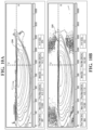
- FIG.4a to FIG.4d shows exemplary luminous intensity distributions of a low beam module (flat) of the vehicle lamp in which a projection lens is made of different grades of diffusive materials, according to an exemplary embodiment of the present invention.
- the low beam module with diffusive projection lens was used to perform photometric simulations, it is understood to a person skilled in the art that a high beam module or a fog beam module with diffusive projection lens may be used to perform the photometric simulation.
- the projection lens was made with different grades of diffusive materials having different diffusivities to perform the photometric simulations.
- different grades of diffusive material include PMMA 8N LD12, PMMA 8N LD24, and PMMA 8N LD 48, and PMMA 8N LD96.
- the above mentioned grades of diffusive materials were used for producing the projection lens.
- any type of diffusive material may be used to obtain the diffusive projection lens.
- the diffusive material PMMA 8N LD96 has less diffusivity compared to the diffusivity of PMMA 8N LD 48, which further has less diffusivity compared to diffusivity of PMMA 8N LD24. Further, PMMA 8N LD24 has less diffusivity compared to diffusivity PMMA 8N LD12.
- the horizontal axis H and vertical axis V identify horizontal and vertical planes intersecting both the center of the headlamp and the screen.
- Fig.4a shows luminous intensity distribution of the low beam module when the projection lens is made from PMMA 8N LD96 (least diffusive material).
- reference numeral 160a refers to the luminous intensity distribution.
- the maximum intensity is located at a position of -8.6 degrees along the horizontal axis and -2 degrees along the vertical axis.
- the maximum intensity illustrated is 15900 cd having a total lumen flux of 853.
- Fig.4b shows luminous intensity distribution when the projection lens is made from PMMA 8N LD48.
- reference numeral 160b refers to the luminous intensity distribution.
- the maximum intensity is located at a position of -7.3 degrees along the horizontal axis and -2 degrees along the vertical axis.
- the maximum intensity illustrated is 15700 cd having a total lumen flux of 834.
- Fig.4d shows luminous intensity distribution when the projection lens is made from PMMA 8N LD12.
- reference numeral 160d refers to the luminous intensity distribution.
- the maximum intensity is located at a position of -7.3 degrees along the horizontal axis and -2 degrees along the vertical axis.
- the maximum intensity illustrated is 13800 cd having a total lumen flux of 750.
- the scattering of the light has increased.
- the scattering of the light is more in Fig.4b compared to the scattering of the light in the Fig.4a .
- the scattering of the light is more in Fig.4c compared to the scattering of the light in the Fig.4b
- the scattering of the light is more in Fig.4d compared to the scattering of the light in the Fig.4c .
- the selection of grade of diffusive material is important such that scattering of the light can be increased for performing the second lighting function, without degrading the beam pattern but adds the sign light and softens the gradient at the cut-off of the beam pattern. Further, the photometric simulation results show that the use of diffusive material for projection lens is feasible.
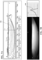
- FIG.6a shows test results indicating exemplary luminous intensity distributions of a flat low beam module of the vehicle lamp with a diffusive projection lens, according to an embodiment of the present invention.
- reference numeral 170a refers to the luminous intensity distribution.
- the maximum intensity is located at a position of -8.6 degrees along the horizontal axis and -2 degrees along the vertical axis.
- the maximum intensity illustrated is 14500 cd having a total lumen flux of 797.
- Fig.6b shows the luminous distribution of Fig.6a projected on a test surface (wall) and a curve 170b indicating a variation of gradient along the beam pattern.
- the sharpness of the cut-off of the light beam pattern by adding the diffusive material As can be understood from the Fig.5a and Fig.6a that the sharpness of the cut-off of the light beam pattern by adding the diffusive material. Further, from the curves of Fig.5b and Fig.6b , it is understood that the gradient has reduced to 0.22 from 0.24 when the projection lens is made of diffusive material. Because of presence of scattering bodies in the diffusive material, the gradient at the cut-off of the beam pattern has reduced to 0.22 from 0.24. Thus, the gradient of the beam is smoothened by using the diffusive projection lens, without effecting the low beam function.
- the photometric simulation tests were performed to understand the performance of a full low beam module (kink and flat) with a diffusive projection lens.
- the full low beam module may include a flat low beam module and a kink low beam module.
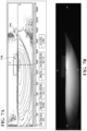
- FIG.7a shows test results indicating exemplary luminous intensity distributions of the full low beam module of the vehicle lamp with a diffusive projection lens, according to an embodiment of the present invention.
- the reference numeral 175a refers to the luminous intensity distribution.
- the maximum intensity is located at a position of 0.6 degrees along the horizontal axis and -1.1 degrees along the vertical axis.
- the maximum intensity illustrated is 49600 cd having a total lumen flux of 970.
- Fig.7b shows the luminous distribution of Fig.7a projected on a test surface (wall), according to an embodiment of the present invention.
- the total flux of the full low beam module with the diffusive projection lens is about 970 lumens.
- the diffusive projection lens 120 aids in adding or improving the sign light 175b.
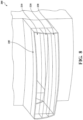
- Fig.8 shows an optical system 200 in which the projection lens 205 is produced by multi-shot injection process, according to another embodiment of the present invention.
- the projection lens 205 may be formed from various opalescent or diffusive materials with different zones 210, 220, and 230 with different levels of diffusivity.
- a multi-shot injection process may be used to form the projection lens 205 with different zones 210, 220, and 230.
- the multi-shot injection process is very well known to a person skilled in the art and hence not discussed in detail.
- the projection lens 205 shown in the Fig.8 is formed with three different zones 210, 220 and 230 having different levels of the diffusivity from application of various grades of opalescent or diffusive materials.
- Fig.9a and Fib.9b shows a lit aspect of the lighting module having a multi-shot projection lens of the Fig.8 , made without and with diffusive material, respectively, according to an embodiment of the present invention.
- Reference numeral 240 refers to the lit of the light pattern when the multi-shot projection lens is made of exemplary lens material from various opalescent or diffusive grades or with no diffusive material.
- reference numeral 245 in the Fig.9b refers to lit of the light pattern when the multi-shot projection lens is made of exemplary mentioned diffusive material. It can be clearly seen from the Fig.9b that the addition of the diffusive material has improved the overall lit-aspect and is made more homogeneous also.
- FIG.10a and FIG.10b shows test results indicating exemplary luminous intensity distributions of a flat low beam module of the vehicle lamp having multi-shot projection lens, without diffusivity and with diffusivity, respectively, according to an exemplary embodiment of the present invention.
- Fig.10a shows luminous distribution of the flat low beam module having multi-shot lens made of normal lens material with no diffusive material.
- reference numeral 250 refers to the luminous intensity distribution.
- the maximum intensity is located at a position of -8.3 degrees along the horizontal axis and -2.1 degrees along the vertical axis.
- the maximum intensity illustrated is 15900 cd having a total lumen flux of 857.
- Fig.10b shows luminous distribution of the flat low beam module with diffusive multi-shot projection lens.
- reference numeral 255 refers to the luminous intensity distribution.
- the maximum intensity is located at a position of -9.8 degrees along the horizontal axis and -1.9 degrees along the vertical axis.
- the maximum intensity illustrated is 14300 cd having a total lumen flux of 804.
- the multi-shot projection lens was diffusive with diffusive material PMMA 8N LD12.
- the gradient obtained with diffusive multi-shot projection lens is about 0.25, whereas the gradient obtained with multi-shot projection lens with no diffusion is about 0.28.
- the gradient has improved, without degrading the performance of the low beam.
- the luminous efficiency calculated is 0.48 with no diffusion on the multi-shot projection lens, and the luminous efficiency is about 0.45 with diffusive multi-shot projection lens.
- the addition of the diffusive material aids in sharpening the gradient at the cut-off the beam pattern, without degrading the performance of the low beam.
- the addition of diffusive material to the projection lens helps in adding sign light to the beam pattern, without using complex optical elements. Further, aids in sharpening the gradient at the cut-off the beam pattern. In addition, the diffusive material would help to provide a uniform lit aspect by scattering light guided in the material.
- any numerical values recited herein include all values from the lower value to the upper value in increments of one unit provided that there is a separation of at least two (2) units between any lower value and any higher value.
- the amount of a component or a value of a process variable such as, for example, temperature, pressure, time and the like is, for example, from 1 to 90, preferably from 20 to 80, more preferably from 30 to 70, it is intended that values such as 15 to 85, 22 to 68, 43 to 51, 30 to 32 etc. are expressly enumerated in this specification.
- one unit is considered to be 0.0001, 0.001, 0.01 or 0.1 as appropriate.
Landscapes
- Engineering & Computer Science (AREA)
- General Engineering & Computer Science (AREA)
- Physics & Mathematics (AREA)
- Microelectronics & Electronic Packaging (AREA)
- Optics & Photonics (AREA)
- Transportation (AREA)
- Mechanical Engineering (AREA)
- Non-Portable Lighting Devices Or Systems Thereof (AREA)
Description
- The present invention relates to the motor vehicle lighting field. More specifically, the invention relates to optical systems applied to vehicle lamps.
- Efforts to improve the lighting efficiency and uniformity, particularly for park, turn, signal, running and signature lamps, which are frequently integrated around headlamps and tail lamps, are an on-going endeavor among Original Equipment Manufacturers (OEM) and the numerous component/system suppliers. Of particular interest is the desire to propagate the light as uniformly as possible. The present invention is directed one such innovation solution to provide a lighting and/or signaling device which can perform multiple lighting functions with using a single projection lens and without using complex optics on the lens, while achieving uniform lit aspect.
- In general, vehicle lamps include one or more optical modules to perform different lighting and/or signalling functions such as low beam function, high beam function, fog function etc. Each module comprises a reflector, a source of light which emits rays of light, and a projection lens. The reflector includes a reflective inner surface in order to reflect towards the projection lens at least part of the rays of light which are emitted by the source of light. The projection lens may be made of glass or of polymer material, for example chosen from the family of polycarbonates or PMMA (polymethyl methacrylate).
- Conventional vehicle lamps further include a folder or a shield to create or form a cut-off in the lighting beam so that glaring on opposite coming vehicles can be prevented. In order to have a sharper cut-off and to perform a sign light function, and to perform other secondary functions, complex optical elements may be required to be added onto the projection lens.
- Further, the outer lens or the projection lens of the conventional vehicle lamps may have thickness of about 25mm. Hence, diffusive materials or opalescent materials cannot be added to the existing projection lens as it results in degrading the performance of lighting functions. Further, as the projection lens is thick lens, it increases its weight and complicates the production thereof. The invention herein overcomes one or more of the problems of the known vehicle lamps. Conventional vehicle lamps are disclosed in
JP 2014 060102 A US 2002/093829 A1 ,JP 2012 064535 A WO 2020/025171 A1 . - The present invention is directed to a unique solution to one or more of the problems discussed above. It is believed that that the present invention provides an optical system that is used to provide primary lighting functions (low beam function, high beam function, fog function etc.) and secondary lighting functions (signature lighting function, park function, etc.) by using a single diffusive projection lens and a shaping reflector, and by without using complex optical elements on the projection lens. Further, the optical system may be adapted to add sign light to the beam pattern, and further sharpens the gradient at the cut-off of the beam pattern, without negative impact on the performance of the primary lighting functions, i.e., low beam function, high beam function, and fog function. Thus, with the optical system of the present invention, simultaneous lighting functions can be performed by using a single projection lens.
- Accordingly, pursuant to a first aspect of the present invention, there is contemplated an optical system for an automotive vehicle, the optical system comprises: one or more first optical elements that reflect light rays emitted from a number of first light sources that are configured to perform a first lighting function; a second optical element that is configured to project a light beam transmitted from the one or more first optical elements that are configured to perform the first lighting function, wherein at least a portion of the second optical element is made of a diffusive material; and a number of secondary light sources, wherein the second optical element is configured to receive light rays emitted from the number of secondary light sources and perform a second lighting function by scattering the light rays received from the number of secondary light sources.
- The invention may be further characterized by one or any combination of the features described herein, such as the number of secondary light sources are arranged on at least one of: a number of sides of the second optical element, and a top of the second optical module; the one or more first optical elements are shaping reflectors; the one or more first light sources are arranged at the vicinity of the focus of the one or more first optical elements; the second optical element is a diffusive lens; the second optical element is arranged at a downstream location of the one or more first optical elements in a direction of propagation of associated light rays; the diffusive lens has a thickness of about 2mm to 7mm; the number of secondary light sources are arranged on a top of a flange of the diffusive lens; the number of first light sources and the number of secondary light sources are arranged on a same Printed Circuit Board (PCB); the number of first light sources and the number of secondary light sources are arranged on different PCBs; the first lighting function is one of: a low beam function, a high beam function, and fog function; the second lighting function is one of: signature function, park function; the diffusive material includes at least one of Poly(methyl methacrylate) types: Evonik Acrylite, PMMA 8N LD12, PMMA 8N LD24, and PMMA 8N LD 48, and the like; the second optical element is adapted to produce the light beam pattern with a sharper cut off; top and bottom portions of the second optical element is made of a non-diffusive material and a middle portion of the second optical element is made of the diffusive material; the complete portion of the second optical element is made of the diffusive material; the second optical element is produced by a multi-shot injection process; the second optical element is adapted to increase the sharpness of the cut-off of the light beam pattern with the increased diffusivity of the diffusive material, which is applied to produce the second optical element; and the second optical element is an outer lens of the optical system.
- Accordingly, pursuant to a second aspect of the present invention, there is contemplated a headlamp assembly for an automotive vehicle, the headlamp assembly comprises: a number of low beam modules configured to generate a low beam distribution; a number of high beam modules configured to generate a high beam distribution; and wherein at least one of the low beam modules and the high beam modules includes an optical system comprising: one or more first optical elements that are configured to reflect light rays emitted from a number of first light sources configured to perform a first lighting function; a second optical element arranged at a downstream location of the one or more first optical elements that is configured to project a light beam that is transmitted from the one or more first optical elements configured to perform the first lighting function, wherein at least a portion of the second optical element is made of a diffusive material; and a number of secondary light sources, wherein the second optical element is configured to receive light rays emitted from the number of secondary light sources and perform a second lighting function by scattering the light rays received from the number of secondary light sources.
- It should be appreciated that the above referenced aspects and examples are nonlimiting, as others exist within the present invention, as shown and described herein.
- A more complete appreciation of the invention and many of the attendant advantages thereof will be readily obtained as the same becomes better understood by reference to the detailed description herein when considered in connection with the accompanying drawings, wherein:
-
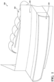
FIG. 1 shows an optical system of a vehicle lamp assembly according to an embodiment of the present invention. -
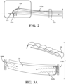
FIG. 2 is a schematic arrangement of different components of the optical system in which a reflector is a shaping reflector and a lens is a diffusive projection lens, according to an embodiment of the present invention. -
FIG. 3a shows arrangement of a shaping reflector, a diffusive projection lens and a secondary light source of the optical system, according to an embodiment of the present invention -
FIG. 3b shows arrangement of a shaping reflector, a diffusive projection lens and a secondary light source of the optical system, according to another embodiment of the present invention. -
Fig.3c shows a path of light rays, in particular, the light rays emitted from a secondary light source when the second light source is arranged as per theFig.3b . -
Figures 4a ,4b ,4c and4d show exemplary luminous intensity distribution results of a low beam module (flat) of the vehicle lamp assembly in which a same projection lens applies different grades of diffusive materials, from minimum to maximum amounts of diffusive material, according to an exemplary embodiment of the present invention. -
FIG.5a shows exemplary luminous intensity distribution of a flat low beam module of the vehicle lamp assembly having a conventional projection lens with no diffusive material, according to an exemplary embodiment of the present invention. -
Fig.5b shows the luminous distribution ofFig.5a projected on a test surface (wall) and a curve indicating a variation of gradient along the beam pattern, according to an exemplary embodiment of the present invention. -
Fig.6a shows exemplary luminous intensity distribution of a flat low beam module of the vehicle amp assembly having a diffusive projection lens, according to an exemplary embodiment of the present invention. -
Fig.6b shows the luminous distribution ofFig.6a projected on a test surface (wall) and a curve indicating a variation of gradient along the beam pattern, according to an exemplary embodiment of the present invention. -
Fig.7a shows exemplary luminous intensity distribution of a full low beam module (flat and kink) of the vehicle lamp assembly having a diffusive projection lens, according to an exemplary embodiment of the present invention. -
Fig.7b shows the luminous distribution ofFig.7a projected on a test surface (wall), according to an exemplary embodiment of the present invention. -
Fig.8 shows an optical system in which the diffusive projection lens is produced by multi-shot injection process, according to another embodiment of the present invention. -
Fig.9a shows an expected lit aspect of the lighting module having a conventional projection lens with no diffusive material, according to an exemplary embodiment of the present invention. -
Fig.9b shows an enhanced lit aspect of the lighting module having a multi-shot diffusive projection lens according to an exemplary embodiment of the present invention. -
FIG.10a shows exemplary luminous intensity distribution of a flat low beam module of the vehicle lamp having multi-shot projection lens with no diffusive material, according to an exemplary embodiment of the present invention. -
FIG.10b shows exemplary luminous intensity distribution of a flat low beam module of the vehicle lamp having multi-shot diffusive projection lens, according to an exemplary embodiment of the present invention. - The present invention relates to an optical system of an automotive vehicle, in particular, of a vehicle lamp. The optical system may be configured to provide primary lighting functions (low beam function, high beam function, fog function etc.) and secondary lighting functions (signature lighting function, park function, etc.) by using a single diffusive projection lens and a shaping reflector, and by without using complex optical elements on the projection lens. Further, the optical system may be adapted to add sign light to the beam pattern, and further sharpens the gradient at the cut-off of the beam pattern, without negative impact on the performance of the primary lighting functions, i.e., low beam function, high beam function, and fog function. Thus, with the optical system of the present invention, simultaneous lighting functions can be performed by using a single projection lens.
-
FIG. 1 shows an optical system of a vehicle lamp assembly according to an embodiment of the present invention. Theoptical system 100 comprises one or more firstoptical elements 110 that reflect light rays emitted from a number offirst light sources 140a (not shown in theFig.1 but shown in theFig.2 ) that are configured to perform a first lighting function.Optical system 100 discussed herein may be a part of a low beam module or high beam module or matrix beam module or a fog beam module. For example, the first or primary lighting functions include one of: a low beam function, a high beam function, and a fog function. For example, a low beam module of the vehicle lamp assembly performs the low beam function and a high beam module of the vehicle lamp assembly performs the high beam function. - In an embodiment, the one or more first
optical elements 110 are shaping reflectors or shaping collectors, which will be explained in detail with regard toFig.2 . Theoptical system 100 further comprises a secondoptical element 120 configured to project a light beam transmitted from the one or more firstoptical elements 110. In an aspect, the secondoptical element 120 is a projection lens or an outer lens of the vehicle lamp assembly. In an embodiment, at least a portion of the secondoptical element 120 is made of a diffusive material. In another embodiment, complete portion of the secondoptical element 120 is made of diffusive material. The second optical element may be referred as a diffusive projection lens as it is made of the diffusive material. Furthermore,Fig.1 's shownoptical system 100 includes ahousing 130 to encapsulate different components of the vehicle lamp assembly. - In addition, the
optical system 100 further comprises a number of secondarylight sources 140b (shown inFig.3a and theFig.3b ). The second optical element or thediffusive projection lens 120 may be configured to receive light rays emitted from the number of secondary light sources and perform a secondary lighting function by scattering the light rays received from the number of secondarylight sources 140b. For example, the secondary lighting function is one of: signature function, park function. In particular, thediffusive projection lens 120 of theoptical system 100 may be adapted to provide the secondary lighting functions and also adds or improves sign light, and further smoothens the gradient, without degrading the performance of the primary lighting functions. In addition, thediffusive projection lens 120 aids in improving beam pattern uniformity. - It is contemplated that relationship between the components and component assemblies are surprisingly important in solving one or more issues described in the background section above. Each of the components and component assemblies and the associated relationships are disclosed in greater detail and specifically in the following paragraphs.
- The major functional aim of the reflector is to capture the greatest possible share of the luminous flux radiated by the light source and to direct this towards the road. There are various different reflector systems available to enable headlamp designers to meet this requirement as effectively as possible.
- Shaping
reflector 110 is a type of reflector which includes a cut-offprofile 135 as a part of the reflector at the bottom of the reflector as shown in theFig.2 . In particular, cut off is produced by a rear edge of the reflective surface of the shaping collector. Thus, the the shield or folder in not required to create the cut-off in the light beam pattern. In general, the shaping collector may include elliptical or parabolic reflective surfaces. - In the
Fig.2 , the shapingreflector 110 shown is an elliptical reflector with a cut-offprofile 135. The cut-offprofile 135 of the shapingreflector 110 helps in creating a cut-off in the light beam .The elliptical reflector is shown in theFig.2 is for the purpose of explanation. However, the reflector can be any type of known reflectors without any limitation. The reflective surface of the shapingreflector 110 is configured to collect the light rays emitted by afirst light source 140a and reflects towards aprojection lens 120, as shown in theFig.2 . Further, theoptical system 100 having the shapingreflector 110 is configured to form a luminous image of the reflective surface. -
Projections lens 120 are intended to project a light beam on the road. In the present invention, the second optical element is aprojection lens 120, which projects the light rays reflected by the shapingreflector 110. Further, theprojection lens 120 also referred as outer lens and the thickness of the projection lens of the conventional vehicle lamps may be about 25mm. Hence, diffusive materials or opalescent materials cannot be added to the existing projection lens as it results in degrading the performance of lighting functions. - The
lens 120 of the present invention is said to be thin, for example with a thickness, along the optical axis of the device that is smaller than 7 mm, in particular because of the small lens height and the long focal length thereof. As the lens has a thickness of about 2mm to 7mm, it allows the use of diffusive materials. - Diffusive material may represent different grades of light-scattering bodies. Diffusive or opalescent materials include materials that promote or aid in scattering light rays emitted from a light source. Without limitation, examples of diffusive or opalescent materials include various grades of silicone, polycarbonate or Poly-methyl methacrylate (PMMA), highly transmissive plastics, such as PS (polystyrene), PMMA are (poly- Methyl methacrylate), COC (cyclic olefine copolymer), PET (polyethylene terephthalate), glass, resin, Evonik Endlighten, or similarly applied materials and applications of various grades of other opalescent material, by examples. Furthermore, different grades of diffusive materials can be used to form the projection lens. For additional examples, different grades of diffusive materials include.at least one of Poly methyl methacrylate types: Evonik Acrylite,
PMMA 8N LD12,PMMA 8N LD24, andPMMA 8N LD 48, and the like. The projection lens, which is made of diffusive material, is referred as a diffusive projection lens. The diffusive projection lens aids in increasing the sharpness of the cut-off of the light beam pattern with the increased diffusivity of the diffusive material. - Light source represents a visually perceived source of electromagnetic radiation or an energized source of visually perceived radiant energy (inclusive of "Visible" light within the electromagnetic spectrum). The light source may include every conventional and suitable lighting element sources such as filament-based or incandescent lamps, fluorescent lamps, arc or gas-discharge type lights, light emitting diodes (LED), or other suitable conventional sources.
- Gradient is a function of intensity and is defined as a log of intensity at point A of the intensity region of the light beam pattern minus the log of intensity at the adjacent point B of the intensity region of the light beam pattern. Gradient is highest at the cut-off of the beam pattern. Generally, gradient is in the range between 0.2 to 0.25.
- A beam pattern having a cut-off profile known by the term "kink" or "elbow. As is known to one skilled in the art, the cut-off is a defined line of cut-off below which light from the headlamp assembly is projected. In general, the light output is below the cut-off which is below the eyes of a driver in an oncoming vehicle.
- The low beam module of a vehicle lamp assembly performs a low beam function to generate a low beam. Low beam provides alight distribution to give adequate forward and lateral illumination without dazzling the oncoming vehicles. Low beam may also be called passing beam or dipped beam.
- The high beam module of a vehicle lamp assembly performs a high beam function to generate a high beam. The high beam is a centre-weighted distribution of light with no control of glare. High beam may also be referenced as main beam or full beam.
- The fog beam module of the vehicle lamp assembly performs a fog beam function to generate a fog beam, which is a wide, bar-shaped beam of light with a sharper cut-off.
- Parking light function is activated to indicate to other drivers of a driver's intention to park a vehicle in an empty parking spot. The parking light function is generally performed by a parking light, which is generally disposed at a rear portion of a vehicle.
- Signature lights are automotive vehicle lamps having a specific shape, design and appearance to help distinguish or identify the vehicle. Signature lights are adapted to perform the signature lighting function.
- The spread of the light above the cut-off of the beam pattern is referred as sign light. Sign light is used to illuminate highway signs, stop signs and the like. In conventional optical systems, special optics may be needed to obtain the sign light. According to the present invention, the diffusive material aids in adding sign light to the beam pattern.
- Diffusivity of the material is defined as a ratio of conductivity to density of the diffusive material. Number of scattering bodies in the diffusive material increases with increased diffusivity.
-
FIG.2 is a schematic arrangement of different components of theoptical system 100 in which a reflector is a shapingreflector 110 and lens is adiffusive projection lens 120 according to an embodiment of the present invention. As previously discussed, the shapingreflector 110 in combination with thediffusive projection lens 120 aids in improving the uniformity of beam pattern of the primary lighting functions such as low beam, high beam, and fog beam. Further, the diffusive projection lens aids in performing the secondary lighting functions, without negative impact on the primary lighting functions. As can be seen from theFig.2 , the light beam emitted from thefirst light source 140a is reflected by the reflecting surface of the shapingreflector 110 and from there the reflected light is directed towards thediffusive projection lens 120 to perform the primary lighting function. Thefirst light sources 140a and the secondarylight source 140b includes a number of Light emitting diodes (LEDs). In an embodiment, thefirst light sources 140a are arranged at the vicinity of the focus of the shapingreflector 110, as shown in theFig.2 . For the sake of brevity, oneshaping reflector 110 is shown in theFig.2 . However, firstoptical element 110 may include a plurality of shaping reflectors arranged in a transverse series as shown in theFig.3a and theFig.3b . The light emitted from thefirst light source 140a is reflected by the shapingreflectors 110 and propagated through the thin cross section of thediffusive projection lens 120 to perform the first lighting function. - In an embodiment of the present invention, the secondary
light sources 140b may be positioned at the sides of thediffusive projection lens 120 as shown in theFig.3a . In this arrangement, the light emitted from the secondarylight sources 140b is propagated through a longer path and thereby increases the scattering of the light. For instance, thediffusive projection lens 120 may be modified at the sides to arrange the secondarylight sources 140b at the sides to pipe light through thediffusive projection lens 120, then the light would be scattered by the diffusive material to be used as signature or park function. - In another embodiment of the present invention, the secondary
light sources 140b may be positioned on a top of thediffusive projection lens 120 as shown in theFig.3b . For example, the secondarylight sources 140b may be positioned on a top of a flange of the diffusive projection lens. With this arrangement, the light emitted from the secondarylight sources 140b is guided towards thediffusive projection lens 120 through the one or more light guides 150 (shown inFig.3c ), and then then the light would be scattered by the diffusive material to be used as signature or park function. - Yet, in another embodiment, some of the secondary light sources 140d may be positioned at the sides of the
diffusive projection lens 120 and remaining secondary light sources 140d may be positioned on the top of the module. -
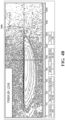
FIG.4a to FIG.4d shows exemplary luminous intensity distributions of a low beam module (flat) of the vehicle lamp in which a projection lens is made of different grades of diffusive materials, according to an exemplary embodiment of the present invention. Although, the low beam module with diffusive projection lens was used to perform photometric simulations, it is understood to a person skilled in the art that a high beam module or a fog beam module with diffusive projection lens may be used to perform the photometric simulation. The projection lens was made with different grades of diffusive materials having different diffusivities to perform the photometric simulations. For example, different grades of diffusive material includePMMA 8N LD12,PMMA 8N LD24, andPMMA 8N LD 48, andPMMA 8N LD96. For the sake of brevity, the above mentioned grades of diffusive materials were used for producing the projection lens. However, it is understood to a person skilled in the art that any type of diffusive material may be used to obtain the diffusive projection lens. - For instance, the
diffusive material PMMA 8N LD96 has less diffusivity compared to the diffusivity ofPMMA 8N LD 48, which further has less diffusivity compared to diffusivity ofPMMA 8N LD24. Further,PMMA 8N LD24 has less diffusivity compared todiffusivity PMMA 8N LD12. - In the
Fig.4a to Fig.4d , the horizontal axis H and vertical axis V identify horizontal and vertical planes intersecting both the center of the headlamp and the screen. -
Fig.4a shows luminous intensity distribution of the low beam module when the projection lens is made fromPMMA 8N LD96 (least diffusive material). In theFig.4a , reference numeral 160a refers to the luminous intensity distribution. The maximum intensity is located at a position of -8.6 degrees along the horizontal axis and -2 degrees along the vertical axis. The maximum intensity illustrated is 15900 cd having a total lumen flux of 853. -
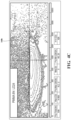
Fig.4b shows luminous intensity distribution when the projection lens is made fromPMMA 8N LD48. In theFig.4b ,reference numeral 160b refers to the luminous intensity distribution. The maximum intensity is located at a position of -7.3 degrees along the horizontal axis and -2 degrees along the vertical axis. The maximum intensity illustrated is 15700 cd having a total lumen flux of 834. -
Fig.4c shows luminous intensity distribution when the projection lens is made fromPMMA 8N LD24. In theFig.4c ,reference numeral 160c refers to the luminous intensity distribution. The maximum intensity is located at a position of -8.2 degrees along the horizontal axis and -2 degrees along the vertical axis. The maximum intensity illustrated is 14900 cd having a total lumen flux of 806. - Further,
Fig.4d shows luminous intensity distribution when the projection lens is made fromPMMA 8N LD12. In theFig.4d ,reference numeral 160d refers to the luminous intensity distribution. The maximum intensity is located at a position of -7.3 degrees along the horizontal axis and -2 degrees along the vertical axis. The maximum intensity illustrated is 13800 cd having a total lumen flux of 750. - It may be seen in
Fig.4a to Fig.4d that the luminous intensity distribution or the light beam patterns 160a 160b, 160c, 160d contains an upper flat cut-off 162 essentially level with the horizontal axis H. The cut-off is not perfectly straight; it has a curvature that corresponds to aberrations in the image thus produced. As can be seen from theFig.4a to Fig.4d , the cut-off is sharpened with the increase of diffusivity. - Further, as can been from the
Fig.4a to Fig.4d , with the increase in the diffusivity of the diffusive material, the scattering of the light has increased. For instance, the scattering of the light is more inFig.4b compared to the scattering of the light in theFig.4a . Further, the scattering of the light is more inFig.4c compared to the scattering of the light in theFig.4b , and the scattering of the light is more inFig.4d compared to the scattering of the light in theFig.4c . Further, it can be observed from theFig.4a to Fig.4b that total output flux of the low beam module (flat) has decreased with increased diffusivity of the projection lens. Hence, the selection of grade of diffusive material is important such that scattering of the light can be increased for performing the second lighting function, without degrading the beam pattern but adds the sign light and softens the gradient at the cut-off of the beam pattern. Further, the photometric simulation results show that the use of diffusive material for projection lens is feasible. - In another exemplary embodiment of the present invention, the photometric simulations were performed to understand the performance of a flat low beam module with a conventional projection lens and with a diffusive projection lens.
-
FIG.5a shows test results indicating exemplary luminous intensity distributions of a flat low beam module of the vehicle lamp with no diffusivity of the projection lens, according to an embodiment of the present invention. In theFig.5a ,reference numeral 165a refers to the luminous intensity distribution. The maximum intensity is located at a position of -8.3 degrees along the horizontal axis and -2.1 degrees along the vertical axis. The maximum intensity illustrated is 15900 cd having a total lumen flux of 857.Fig.5b shows the luminous distribution ofFig.5a projected on a test surface (wall) and acurve 165b indicating a variation of gradient along the beam pattern. -
FIG.6a shows test results indicating exemplary luminous intensity distributions of a flat low beam module of the vehicle lamp with a diffusive projection lens, according to an embodiment of the present invention. In theFig.6a ,reference numeral 170a refers to the luminous intensity distribution. The maximum intensity is located at a position of -8.6 degrees along the horizontal axis and -2 degrees along the vertical axis. The maximum intensity illustrated is 14500 cd having a total lumen flux of 797.Fig.6b shows the luminous distribution ofFig.6a projected on a test surface (wall) and acurve 170b indicating a variation of gradient along the beam pattern. - As can be understood from the
Fig.5a andFig.6a that the sharpness of the cut-off of the light beam pattern by adding the diffusive material. Further, from the curves ofFig.5b andFig.6b , it is understood that the gradient has reduced to 0.22 from 0.24 when the projection lens is made of diffusive material. Because of presence of scattering bodies in the diffusive material, the gradient at the cut-off of the beam pattern has reduced to 0.22 from 0.24. Thus, the gradient of the beam is smoothened by using the diffusive projection lens, without effecting the low beam function. Further, it can be observed from the curves of theFig.5b and theFig.6b that the gradient is highest at the cut-off and it decreases gradually down in the beam pattern, i.e., in vertically downward direction. Thus, the diffusive projection lens aids in softening the gradient, and has minimum impact on hot spot performance. This allows the diffusive projection lens to be used as secondary function. Thus, the photometric simulation results shown in theFig.5a andFig.6a shows that the diffusive material improves the low beam performance, while allowing to perform the secondary function. - In another exemplary embodiment of the present invention, the photometric simulation tests were performed to understand the performance of a full low beam module (kink and flat) with a diffusive projection lens. For example, the full low beam module may include a flat low beam module and a kink low beam module.
FIG.7a shows test results indicating exemplary luminous intensity distributions of the full low beam module of the vehicle lamp with a diffusive projection lens, according to an embodiment of the present invention. In theFig.7a , thereference numeral 175a refers to the luminous intensity distribution. The maximum intensity is located at a position of 0.6 degrees along the horizontal axis and -1.1 degrees along the vertical axis. The maximum intensity illustrated is 49600 cd having a total lumen flux of 970.Fig.7b shows the luminous distribution ofFig.7a projected on a test surface (wall), according to an embodiment of the present invention. As can be seen from theFig.7a , the total flux of the full low beam module with the diffusive projection lens is about 970 lumens. Further, as can be seen from theFig.7a , thediffusive projection lens 120 aids in adding or improving the sign light 175b. -
Fig.8 shows anoptical system 200 in which theprojection lens 205 is produced by multi-shot injection process, according to another embodiment of the present invention. According to this embodiment, theprojection lens 205 may be formed from various opalescent or diffusive materials withdifferent zones projection lens 205 withdifferent zones projection lens 205 shown in theFig.8 is formed with threedifferent zones -
Fig.9a and Fib.9b shows a lit aspect of the lighting module having a multi-shot projection lens of theFig.8 , made without and with diffusive material, respectively, according to an embodiment of the present invention.Reference numeral 240 refers to the lit of the light pattern when the multi-shot projection lens is made of exemplary lens material from various opalescent or diffusive grades or with no diffusive material. Further,reference numeral 245 in theFig.9b refers to lit of the light pattern when the multi-shot projection lens is made of exemplary mentioned diffusive material. It can be clearly seen from theFig.9b that the addition of the diffusive material has improved the overall lit-aspect and is made more homogeneous also. - Furthermore, the addition of diffusive material aids the dead region of the lens to light. In
Fig.9b , the illuminated portion is made of diffusive material and a portion outside the illuminating portion is made of non-diffusive material. -
FIG.10a and FIG.10b shows test results indicating exemplary luminous intensity distributions of a flat low beam module of the vehicle lamp having multi-shot projection lens, without diffusivity and with diffusivity, respectively, according to an exemplary embodiment of the present invention.Fig.10a shows luminous distribution of the flat low beam module having multi-shot lens made of normal lens material with no diffusive material. In theFig.10a ,reference numeral 250 refers to the luminous intensity distribution. The maximum intensity is located at a position of -8.3 degrees along the horizontal axis and -2.1 degrees along the vertical axis. The maximum intensity illustrated is 15900 cd having a total lumen flux of 857.Fig.10b shows luminous distribution of the flat low beam module with diffusive multi-shot projection lens. In theFig.10b ,reference numeral 255 refers to the luminous intensity distribution. The maximum intensity is located at a position of -9.8 degrees along the horizontal axis and -1.9 degrees along the vertical axis. The maximum intensity illustrated is 14300 cd having a total lumen flux of 804.For instance, the multi-shot projection lens was diffusive withdiffusive material PMMA 8N LD12. The gradient obtained with diffusive multi-shot projection lens is about 0.25, whereas the gradient obtained with multi-shot projection lens with no diffusion is about 0.28. Thus, with the use of the diffusive material, the gradient has improved, without degrading the performance of the low beam. For instance, the luminous efficiency calculated is 0.48 with no diffusion on the multi-shot projection lens, and the luminous efficiency is about 0.45 with diffusive multi-shot projection lens. Hence, the addition of the diffusive material aids in sharpening the gradient at the cut-off the beam pattern, without degrading the performance of the low beam. - Thus, the addition of diffusive material to the projection lens helps in adding sign light to the beam pattern, without using complex optical elements. Further, aids in sharpening the gradient at the cut-off the beam pattern. In addition, the diffusive material would help to provide a uniform lit aspect by scattering light guided in the material.
- Although the present disclosure is provided with references to figures, all of the embodiments shown in figures are intended to explain the preferred embodiments of the present invention by ways of examples, instead of being intended to limit the present invention.
- Any numerical values recited herein include all values from the lower value to the upper value in increments of one unit provided that there is a separation of at least two (2) units between any lower value and any higher value. As an example, if it is stated that the amount of a component or a value of a process variable such as, for example, temperature, pressure, time and the like is, for example, from 1 to 90, preferably from 20 to 80, more preferably from 30 to 70, it is intended that values such as 15 to 85, 22 to 68, 43 to 51, 30 to 32 etc. are expressly enumerated in this specification. For values which are less than one, one unit is considered to be 0.0001, 0.001, 0.01 or 0.1 as appropriate. These are only examples of what is specifically intended and all possible combinations of numerical values between the lowest value and the highest value enumerated are to be considered to be expressly stated in this application in a similar manner.
- Unless otherwise stated, all ranges include both endpoints and all numbers between the endpoints. The use of "about" or "approximately" in connection with a range applies to both ends of the range. Thus, "about 20 to 30" is intended to cover "about 20 to about 30", inclusive of at least the specified endpoints.
-
-
Optical System 100 - First optical element or shaping
reflector 110 - Second optical element or
Diffusive projection lens 120 -
Housing 130 - Cut-off profile of the shaping
reflector 135 - Diffusive or Opalescent Material 136
-
First light sources 140a - Secondary
light sources 140b - Light rays from
first light source 145a - Light rays from the second
light source 145b -
Light guide 150 - Luminous intensity distribution (Projection lens made of PMMA8N LD96) 160a
- Luminous intensity distribution (Projection lens made of PMMA8N LD48) 160b
- Luminous intensity distribution (Projection lens made of PMMA8N LD24) 160c
- Luminous intensity distribution (Projection lens made of PMMA8N LD12) 160d
- Cut-off of
beam pattern 162 - Luminous intensity distribution of a flat low beam module (Projection lens with NO diffusive material) 165a
-
Gradient curve 165b - Luminous intensity distribution of a flat low beam module (Projection lens with diffusive material) 170a
-
Gradient curve 170b - Luminous intensity distribution of a full low beam module (Projection lens with diffusive material) 175a
- Sign light 175b
- Optical system with
multi-shot projection lens 200 - Multi-shot
diffusive projection lens 205 - Diffèrent zones of multi-shot
diffusive projection lens - Lit aspect with no diffusion of
projection lens 240 - Lit aspect with
diffusive projection lens 245 - Luminous intensity distribution of a flat low beam module having multi-shot projection lens with no
diffusive material 250 - Luminous intensity distribution of a flat low beam module having multi-shot projection lens with no
diffusive material 255
Claims (13)
- An optical system (100) for an automotive vehicle, the optical system comprises:a number of first light sources (140a),a number of first optical elements (110) that are configured to reflect light emitted from the number of first light sources (140a);a second optical element (120) configured to project light transmitted from the number of first optical elements (110), the first light sources (140a), the first optical elements (110) and the second optical element (120) being configured to perform a first lighting function; anda number of secondary light sources (140b), wherein the second optical element (120) is configured to receive light emitted from the number of secondary light sources (140b) and is configured to perform a second lighting function by scattering light received from the number of secondary light sources (140b)characterized in that at least a portion of the second optical element (120) is made of a diffusive material;wherein the second optical element (120) is a diffusive projection lens produced by multi-shot injection process formed from various opalescent or diffusive materials with different zones (210, 220, 230) having different levels of diffusivity form application of various grades of opalescent or diffusive materials.
- The optical system (100) of claim 1, wherein the number of secondary light sources (140b) are arranged on at least one of: a number of sides of the second optical element (120), and a top of the second optical element (120).
- The optical system (100) of claim 1, wherein the first optical elements (110) are shaping reflectors.
- The optical system (100) of claim 1, wherein the first light sources (140a) are arranged at the vicinity of a focus of the first optical elements (110).
- The optical system of claim 1, wherein the diffusive lens has a thickness of about 2mm to 7mm.
- The optical system of claim 1, wherein the number of secondary light sources are arranged on a top of a flange of the diffusive lens.
- The optical system (100) of claim 1, wherein the number of first light sources (140a) and the number of secondary light sources (140b) are arranged on a same Printed Circuit Board (PCB).
- The optical system (100) of claim 1, wherein the number of first light sources (140a) and the number of secondary light sources (140b) are arranged on different PCBs.
- The optical system (100) of claim 1, wherein the first lighting function is one of: a low beam function, a high beam function and a fog function.
- The optical system (100) of claim 1, wherein the second lighting function is one of: a signature function, a park function.
- The optical system (100) of claim 1, wherein the diffusive material includes at least one of Poly methyl methacrylate types: Evonik Acrylite, PMMA 8N LD12, PMMA 8N LD24, and PMMA 8N LD 48, and the like.
- The optical system (100) of claim 1, wherein top and bottom portions of the second optical element (120) is made of a non-diffusive material and a middle portion of the second optical element is made of the diffusive material.
- A headlamp assembly of an automotive vehicle, the headlamp assembly comprises:a number of low beam modules configured to generate a low beam distribution;a number of high beam modules configured to generate a high beam distribution; andwherein at least one of the number of low beam modules and the number of high beam modules includes an optical system (100) according to claim 1.
Applications Claiming Priority (2)
| Application Number | Priority Date | Filing Date | Title |
|---|---|---|---|
| US17/108,418 US11512828B2 (en) | 2020-12-01 | 2020-12-01 | Automotive lamp optical system with light diffusive projection lens |
| PCT/EP2021/083772 WO2022117649A1 (en) | 2020-12-01 | 2021-12-01 | Automotive lamp optical system with light diffusive projection lens |
Publications (2)
| Publication Number | Publication Date |
|---|---|
| EP4255775A1 EP4255775A1 (en) | 2023-10-11 |
| EP4255775B1 true EP4255775B1 (en) | 2025-07-09 |
Family
ID=79185451
Family Applications (1)
| Application Number | Title | Priority Date | Filing Date |
|---|---|---|---|
| EP21835596.4A Active EP4255775B1 (en) | 2020-12-01 | 2021-12-01 | Automotive lamp optical system with light diffusive projection lens |
Country Status (4)
| Country | Link |
|---|---|
| US (2) | US11512828B2 (en) |
| EP (1) | EP4255775B1 (en) |
| CN (1) | CN116490724A (en) |
| WO (1) | WO2022117649A1 (en) |
Families Citing this family (4)
| Publication number | Priority date | Publication date | Assignee | Title |
|---|---|---|---|---|
| CN211289915U (en) * | 2019-11-14 | 2020-08-18 | 沈阳法雷奥车灯有限公司 | Lamp for vehicle and vehicle |
| WO2022020818A1 (en) * | 2020-07-24 | 2022-01-27 | Lumileds Llc | Lighting module for a vehicle headlamp |
| FR3119440B1 (en) * | 2021-01-29 | 2024-01-12 | Valeo Vision | Road lighting device for a motor vehicle |
| FR3139375B1 (en) * | 2022-09-06 | 2024-10-04 | Valeo Vision | Road lighting module with upward-directed light source |
Family Cites Families (25)
| Publication number | Priority date | Publication date | Assignee | Title |
|---|---|---|---|---|
| US5567034A (en) | 1992-07-28 | 1996-10-22 | Bayerische Motoren Werke Ag | Motor vehicle headlamp |
| FR2819040B1 (en) | 2001-01-02 | 2003-09-12 | Valeo Vision | OPTICAL OR STYLE COMPONENT FOR A LIGHTING OR SIGNALING DEVICE FOR A MOTOR VEHICLE |
| US7297381B2 (en) | 2005-05-20 | 2007-11-20 | General Electric Company | Light diffusing films, methods of making the same, and articles using the same |
| FR2925656B1 (en) | 2007-12-21 | 2013-08-23 | Holophane | AUTOMOTIVE VEHICLE LIGHTING MODULE LENS |
| US8177408B1 (en) | 2008-02-15 | 2012-05-15 | Fusion Optix, Inc. | Light filtering directional control element and light fixture incorporating the same |
| US8573616B2 (en) | 2009-05-29 | 2013-11-05 | Hydema Produktion A/S | Suspension system with inclination stabilization |
| US9134474B2 (en) * | 2010-03-16 | 2015-09-15 | Toyota Motor Engineering & Manufacturing North America, Inc. | Headlamp bulb type light pipe |
| JP2012064535A (en) | 2010-09-17 | 2012-03-29 | Koito Mfg Co Ltd | Lamp fitting for vehicle |
| US8573816B2 (en) | 2011-03-15 | 2013-11-05 | Cree, Inc. | Composite lens with diffusion |
| US8752986B2 (en) * | 2012-02-21 | 2014-06-17 | Toyota Motor Engineering & Manufacturing North America, Inc. | Vehicle lamp assembly having uniform lit appearance |
| JP6175224B2 (en) | 2012-09-19 | 2017-08-02 | 株式会社小糸製作所 | Vehicle lighting |
| JP6166541B2 (en) * | 2013-01-30 | 2017-07-19 | スタンレー電気株式会社 | Vehicle lighting |
| JP6292653B2 (en) * | 2013-07-02 | 2018-03-14 | 株式会社小糸製作所 | Vehicle lighting |
| JP6235948B2 (en) * | 2014-03-27 | 2017-11-22 | 株式会社小糸製作所 | Vehicle lighting |
| JP2015215946A (en) * | 2014-05-07 | 2015-12-03 | 市光工業株式会社 | Vehicle lighting |
| JP6457793B2 (en) * | 2014-11-20 | 2019-01-23 | 株式会社小糸製作所 | Beacon light |
| JP6411950B2 (en) * | 2015-06-08 | 2018-10-24 | 本田技研工業株式会社 | Light guide lens and vehicle lamp |
| JP6714379B2 (en) * | 2016-02-17 | 2020-06-24 | 株式会社小糸製作所 | Vehicle lighting |
| JP2018137144A (en) * | 2017-02-22 | 2018-08-30 | 株式会社小糸製作所 | Vehicle lighting |
| US10663138B2 (en) | 2017-07-20 | 2020-05-26 | Valeo North America, Inc. | Light reflector systems and methods |
| JP7020259B2 (en) * | 2018-04-09 | 2022-02-16 | トヨタ自動車株式会社 | Vehicle lighting |
| US10400981B1 (en) * | 2018-05-18 | 2019-09-03 | Honda Motor Co., Ltd. | Lighting device |
| FR3084728B1 (en) | 2018-07-31 | 2021-03-19 | Valeo Vision | LIGHT MODULE IMAGING THE ILLUMINATED SURFACE OF A COLLECTOR |
| FR3085640B1 (en) * | 2018-09-12 | 2022-08-05 | Valeo Vision | COMPACT OPTICAL SYSTEM FOR MOTOR VEHICLE CABIN |
| EP3739259A1 (en) * | 2019-05-13 | 2020-11-18 | HELLA Saturnus Slovenija d.o.o. | Optical system for homogenous surface illumination |
-
2020
- 2020-12-01 US US17/108,418 patent/US11512828B2/en active Active
-
2021
- 2021-12-01 EP EP21835596.4A patent/EP4255775B1/en active Active
- 2021-12-01 CN CN202180076930.3A patent/CN116490724A/en active Pending
- 2021-12-01 WO PCT/EP2021/083772 patent/WO2022117649A1/en not_active Ceased
-
2022
- 2022-10-31 US US18/051,293 patent/US11761602B2/en active Active
Also Published As
| Publication number | Publication date |
|---|---|
| US20220170606A1 (en) | 2022-06-02 |
| WO2022117649A1 (en) | 2022-06-09 |
| US11761602B2 (en) | 2023-09-19 |
| EP4255775A1 (en) | 2023-10-11 |
| US11512828B2 (en) | 2022-11-29 |
| CN116490724A (en) | 2023-07-25 |
| US20230093259A1 (en) | 2023-03-23 |
Similar Documents
| Publication | Publication Date | Title |
|---|---|---|
| EP4255775B1 (en) | Automotive lamp optical system with light diffusive projection lens | |
| CN100578075C (en) | car headlights | |
| KR20070101154A (en) | Car luminaires | |
| JP2008251243A (en) | Vehicle headlamp unit | |
| CN203963757U (en) | Automotive lamp | |
| JP5152563B2 (en) | Vehicle headlamp | |
| CN104344304B (en) | Optical module and the Vehicular lamp including the optical module | |
| CN113028355B (en) | Car light optical assembly, illumination optical device and vehicle | |
| CN103062695A (en) | A lamp apparatus for vehicles | |
| JP7479374B2 (en) | Optical system for headlamps | |
| KR101021929B1 (en) | Car lamp assembly | |
| JP7231726B2 (en) | Lighting unit for automobile floodlight | |
| KR101342060B1 (en) | Automotive lamp assembly | |
| US20220221120A1 (en) | Thin aspect module and optical beam of automotive illumination system | |
| CN118564857A (en) | An optical module | |
| CN110953545A (en) | Lighting structure for headlight III zone, headlight concentrator, automotive lighting module and automobile | |
| JP2010277699A (en) | Vehicle headlamp | |
| CN219346279U (en) | Light guide assembly, lamp device and motor vehicle | |
| KR102002029B1 (en) | Lamp for vehicle | |
| CN223895763U (en) | A lighting device for motor vehicles and a vehicle | |
| CN222480263U (en) | High beam lens module and car light | |
| CN222937655U (en) | Car light | |
| US10161591B2 (en) | Thin wall internal reflection light optic | |
| US12429187B1 (en) | Optical module and vehicle having the same | |
| CN110529817B (en) | Dipped beam unit and dipped beam assembly thereof |
Legal Events
| Date | Code | Title | Description |
|---|---|---|---|
| STAA | Information on the status of an ep patent application or granted ep patent |
Free format text: STATUS: UNKNOWN |
|
| STAA | Information on the status of an ep patent application or granted ep patent |
Free format text: STATUS: THE INTERNATIONAL PUBLICATION HAS BEEN MADE |
|
| PUAI | Public reference made under article 153(3) epc to a published international application that has entered the european phase |
Free format text: ORIGINAL CODE: 0009012 |
|
| STAA | Information on the status of an ep patent application or granted ep patent |
Free format text: STATUS: REQUEST FOR EXAMINATION WAS MADE |
|
| 17P | Request for examination filed |
Effective date: 20230525 |
|
| AK | Designated contracting states |
Kind code of ref document: A1 Designated state(s): AL AT BE BG CH CY CZ DE DK EE ES FI FR GB GR HR HU IE IS IT LI LT LU LV MC MK MT NL NO PL PT RO RS SE SI SK SM TR |
|
| DAV | Request for validation of the european patent (deleted) | ||
| DAX | Request for extension of the european patent (deleted) | ||
| GRAP | Despatch of communication of intention to grant a patent |
Free format text: ORIGINAL CODE: EPIDOSNIGR1 |
|
| STAA | Information on the status of an ep patent application or granted ep patent |
Free format text: STATUS: GRANT OF PATENT IS INTENDED |
|
| RIC1 | Information provided on ipc code assigned before grant |
Ipc: F21W 102/30 20180101ALI20250312BHEP Ipc: F21W 102/16 20180101ALI20250312BHEP Ipc: F21W 104/00 20180101ALI20250312BHEP Ipc: F21W 102/155 20180101ALI20250312BHEP Ipc: F21W 102/13 20180101ALI20250312BHEP Ipc: F21S 43/249 20180101ALI20250312BHEP Ipc: F21S 43/245 20180101ALI20250312BHEP Ipc: F21S 43/239 20180101ALI20250312BHEP Ipc: F21S 43/14 20180101ALI20250312BHEP Ipc: F21S 41/32 20180101ALI20250312BHEP Ipc: F21S 43/20 20180101ALI20250312BHEP Ipc: F21S 41/25 20180101ALI20250312BHEP Ipc: F21S 41/148 20180101ALI20250312BHEP Ipc: B60Q 1/48 20060101AFI20250312BHEP |
|
| INTG | Intention to grant announced |
Effective date: 20250320 |
|
| GRAS | Grant fee paid |
Free format text: ORIGINAL CODE: EPIDOSNIGR3 |
|
| GRAA | (expected) grant |
Free format text: ORIGINAL CODE: 0009210 |
|
| STAA | Information on the status of an ep patent application or granted ep patent |
Free format text: STATUS: THE PATENT HAS BEEN GRANTED |
|
| AK | Designated contracting states |
Kind code of ref document: B1 Designated state(s): AL AT BE BG CH CY CZ DE DK EE ES FI FR GB GR HR HU IE IS IT LI LT LU LV MC MK MT NL NO PL PT RO RS SE SI SK SM TR |
|
| REG | Reference to a national code |
Ref country code: GB Ref legal event code: FG4D |
|
| REG | Reference to a national code |
Ref country code: CH Ref legal event code: EP |
|
| REG | Reference to a national code |
Ref country code: IE Ref legal event code: FG4D |
|
| REG | Reference to a national code |
Ref country code: DE Ref legal event code: R096 Ref document number: 602021033936 Country of ref document: DE |
|
| P01 | Opt-out of the competence of the unified patent court (upc) registered |
Free format text: CASE NUMBER: APP_31349/2025 Effective date: 20250630 |
|
| REG | Reference to a national code |
Ref country code: NL Ref legal event code: MP Effective date: 20250709 |
|
| PG25 | Lapsed in a contracting state [announced via postgrant information from national office to epo] |
Ref country code: PT Free format text: LAPSE BECAUSE OF FAILURE TO SUBMIT A TRANSLATION OF THE DESCRIPTION OR TO PAY THE FEE WITHIN THE PRESCRIBED TIME-LIMIT Effective date: 20251110 |
|
| PG25 | Lapsed in a contracting state [announced via postgrant information from national office to epo] |
Ref country code: NL Free format text: LAPSE BECAUSE OF FAILURE TO SUBMIT A TRANSLATION OF THE DESCRIPTION OR TO PAY THE FEE WITHIN THE PRESCRIBED TIME-LIMIT Effective date: 20250709 |
|
| REG | Reference to a national code |
Ref country code: AT Ref legal event code: MK05 Ref document number: 1811586 Country of ref document: AT Kind code of ref document: T Effective date: 20250709 |
|
| PG25 | Lapsed in a contracting state [announced via postgrant information from national office to epo] |
Ref country code: IS Free format text: LAPSE BECAUSE OF FAILURE TO SUBMIT A TRANSLATION OF THE DESCRIPTION OR TO PAY THE FEE WITHIN THE PRESCRIBED TIME-LIMIT Effective date: 20251109 |
|
| PG25 | Lapsed in a contracting state [announced via postgrant information from national office to epo] |
Ref country code: NO Free format text: LAPSE BECAUSE OF FAILURE TO SUBMIT A TRANSLATION OF THE DESCRIPTION OR TO PAY THE FEE WITHIN THE PRESCRIBED TIME-LIMIT Effective date: 20251009 |
|
| REG | Reference to a national code |
Ref country code: LT Ref legal event code: MG9D |
|
| PG25 | Lapsed in a contracting state [announced via postgrant information from national office to epo] |
Ref country code: AT Free format text: LAPSE BECAUSE OF FAILURE TO SUBMIT A TRANSLATION OF THE DESCRIPTION OR TO PAY THE FEE WITHIN THE PRESCRIBED TIME-LIMIT Effective date: 20250709 |
|
| PG25 | Lapsed in a contracting state [announced via postgrant information from national office to epo] |
Ref country code: FI Free format text: LAPSE BECAUSE OF FAILURE TO SUBMIT A TRANSLATION OF THE DESCRIPTION OR TO PAY THE FEE WITHIN THE PRESCRIBED TIME-LIMIT Effective date: 20250709 |
|
| PG25 | Lapsed in a contracting state [announced via postgrant information from national office to epo] |
Ref country code: HR Free format text: LAPSE BECAUSE OF FAILURE TO SUBMIT A TRANSLATION OF THE DESCRIPTION OR TO PAY THE FEE WITHIN THE PRESCRIBED TIME-LIMIT Effective date: 20250709 |
|
| PGFP | Annual fee paid to national office [announced via postgrant information from national office to epo] |
Ref country code: FR Payment date: 20251230 Year of fee payment: 5 |
|
| PG25 | Lapsed in a contracting state [announced via postgrant information from national office to epo] |
Ref country code: GR Free format text: LAPSE BECAUSE OF FAILURE TO SUBMIT A TRANSLATION OF THE DESCRIPTION OR TO PAY THE FEE WITHIN THE PRESCRIBED TIME-LIMIT Effective date: 20251010 |
|
| PG25 | Lapsed in a contracting state [announced via postgrant information from national office to epo] |
Ref country code: SE Free format text: LAPSE BECAUSE OF FAILURE TO SUBMIT A TRANSLATION OF THE DESCRIPTION OR TO PAY THE FEE WITHIN THE PRESCRIBED TIME-LIMIT Effective date: 20250709 |
|
| PG25 | Lapsed in a contracting state [announced via postgrant information from national office to epo] |
Ref country code: LV Free format text: LAPSE BECAUSE OF FAILURE TO SUBMIT A TRANSLATION OF THE DESCRIPTION OR TO PAY THE FEE WITHIN THE PRESCRIBED TIME-LIMIT Effective date: 20250709 |
|
| PG25 | Lapsed in a contracting state [announced via postgrant information from national office to epo] |
Ref country code: BG Free format text: LAPSE BECAUSE OF FAILURE TO SUBMIT A TRANSLATION OF THE DESCRIPTION OR TO PAY THE FEE WITHIN THE PRESCRIBED TIME-LIMIT Effective date: 20250709 Ref country code: PL Free format text: LAPSE BECAUSE OF FAILURE TO SUBMIT A TRANSLATION OF THE DESCRIPTION OR TO PAY THE FEE WITHIN THE PRESCRIBED TIME-LIMIT Effective date: 20250709 |
|
| PG25 | Lapsed in a contracting state [announced via postgrant information from national office to epo] |
Ref country code: RS Free format text: LAPSE BECAUSE OF FAILURE TO SUBMIT A TRANSLATION OF THE DESCRIPTION OR TO PAY THE FEE WITHIN THE PRESCRIBED TIME-LIMIT Effective date: 20251009 |
|
| PG25 | Lapsed in a contracting state [announced via postgrant information from national office to epo] |
Ref country code: ES Free format text: LAPSE BECAUSE OF FAILURE TO SUBMIT A TRANSLATION OF THE DESCRIPTION OR TO PAY THE FEE WITHIN THE PRESCRIBED TIME-LIMIT Effective date: 20250709 |
|
| PG25 | Lapsed in a contracting state [announced via postgrant information from national office to epo] |
Ref country code: RO Free format text: LAPSE BECAUSE OF FAILURE TO SUBMIT A TRANSLATION OF THE DESCRIPTION OR TO PAY THE FEE WITHIN THE PRESCRIBED TIME-LIMIT Effective date: 20250709 |
|
| PG25 | Lapsed in a contracting state [announced via postgrant information from national office to epo] |
Ref country code: SM Free format text: LAPSE BECAUSE OF FAILURE TO SUBMIT A TRANSLATION OF THE DESCRIPTION OR TO PAY THE FEE WITHIN THE PRESCRIBED TIME-LIMIT Effective date: 20250709 |
|
| PG25 | Lapsed in a contracting state [announced via postgrant information from national office to epo] |
Ref country code: DK Free format text: LAPSE BECAUSE OF FAILURE TO SUBMIT A TRANSLATION OF THE DESCRIPTION OR TO PAY THE FEE WITHIN THE PRESCRIBED TIME-LIMIT Effective date: 20250709 |
|
| PGFP | Annual fee paid to national office [announced via postgrant information from national office to epo] |
Ref country code: DE Payment date: 20251231 Year of fee payment: 5 |
|
| PG25 | Lapsed in a contracting state [announced via postgrant information from national office to epo] |
Ref country code: IT Free format text: LAPSE BECAUSE OF FAILURE TO SUBMIT A TRANSLATION OF THE DESCRIPTION OR TO PAY THE FEE WITHIN THE PRESCRIBED TIME-LIMIT Effective date: 20250709 |