EP4255762B1 - A braking arrangement for heavy duty vehicles - Google Patents
A braking arrangement for heavy duty vehicles Download PDFInfo
- Publication number
- EP4255762B1 EP4255762B1 EP20820076.6A EP20820076A EP4255762B1 EP 4255762 B1 EP4255762 B1 EP 4255762B1 EP 20820076 A EP20820076 A EP 20820076A EP 4255762 B1 EP4255762 B1 EP 4255762B1
- Authority
- EP
- European Patent Office
- Prior art keywords
- braking
- electric machine
- eddy current
- energy absorption
- torque
- Prior art date
- Legal status (The legal status is an assumption and is not a legal conclusion. Google has not performed a legal analysis and makes no representation as to the accuracy of the status listed.)
- Active
Links
Images




Classifications
-
- B—PERFORMING OPERATIONS; TRANSPORTING
- B60—VEHICLES IN GENERAL
- B60L—PROPULSION OF ELECTRICALLY-PROPELLED VEHICLES; SUPPLYING ELECTRIC POWER FOR AUXILIARY EQUIPMENT OF ELECTRICALLY-PROPELLED VEHICLES; ELECTRODYNAMIC BRAKE SYSTEMS FOR VEHICLES IN GENERAL; MAGNETIC SUSPENSION OR LEVITATION FOR VEHICLES; MONITORING OPERATING VARIABLES OF ELECTRICALLY-PROPELLED VEHICLES; ELECTRIC SAFETY DEVICES FOR ELECTRICALLY-PROPELLED VEHICLES
- B60L7/00—Electrodynamic brake systems for vehicles in general
- B60L7/22—Dynamic electric resistor braking, combined with dynamic electric regenerative braking
-
- B—PERFORMING OPERATIONS; TRANSPORTING
- B60—VEHICLES IN GENERAL
- B60K—ARRANGEMENT OR MOUNTING OF PROPULSION UNITS OR OF TRANSMISSIONS IN VEHICLES; ARRANGEMENT OR MOUNTING OF PLURAL DIVERSE PRIME-MOVERS IN VEHICLES; AUXILIARY DRIVES FOR VEHICLES; INSTRUMENTATION OR DASHBOARDS FOR VEHICLES; ARRANGEMENTS IN CONNECTION WITH COOLING, AIR INTAKE, GAS EXHAUST OR FUEL SUPPLY OF PROPULSION UNITS IN VEHICLES
- B60K7/00—Disposition of motor in, or adjacent to, traction wheel
- B60K7/0007—Disposition of motor in, or adjacent to, traction wheel the motor being electric
-
- B—PERFORMING OPERATIONS; TRANSPORTING
- B60—VEHICLES IN GENERAL
- B60L—PROPULSION OF ELECTRICALLY-PROPELLED VEHICLES; SUPPLYING ELECTRIC POWER FOR AUXILIARY EQUIPMENT OF ELECTRICALLY-PROPELLED VEHICLES; ELECTRODYNAMIC BRAKE SYSTEMS FOR VEHICLES IN GENERAL; MAGNETIC SUSPENSION OR LEVITATION FOR VEHICLES; MONITORING OPERATING VARIABLES OF ELECTRICALLY-PROPELLED VEHICLES; ELECTRIC SAFETY DEVICES FOR ELECTRICALLY-PROPELLED VEHICLES
- B60L58/00—Methods or circuit arrangements for monitoring or controlling batteries or fuel cells, specially adapted for electric vehicles
- B60L58/10—Methods or circuit arrangements for monitoring or controlling batteries or fuel cells, specially adapted for electric vehicles for monitoring or controlling batteries
- B60L58/12—Methods or circuit arrangements for monitoring or controlling batteries or fuel cells, specially adapted for electric vehicles for monitoring or controlling batteries responding to state of charge [SoC]
- B60L58/15—Preventing overcharging
-
- B—PERFORMING OPERATIONS; TRANSPORTING
- B60—VEHICLES IN GENERAL
- B60L—PROPULSION OF ELECTRICALLY-PROPELLED VEHICLES; SUPPLYING ELECTRIC POWER FOR AUXILIARY EQUIPMENT OF ELECTRICALLY-PROPELLED VEHICLES; ELECTRODYNAMIC BRAKE SYSTEMS FOR VEHICLES IN GENERAL; MAGNETIC SUSPENSION OR LEVITATION FOR VEHICLES; MONITORING OPERATING VARIABLES OF ELECTRICALLY-PROPELLED VEHICLES; ELECTRIC SAFETY DEVICES FOR ELECTRICALLY-PROPELLED VEHICLES
- B60L7/00—Electrodynamic brake systems for vehicles in general
- B60L7/02—Dynamic electric resistor braking
- B60L7/08—Controlling the braking effect
-
- B—PERFORMING OPERATIONS; TRANSPORTING
- B60—VEHICLES IN GENERAL
- B60L—PROPULSION OF ELECTRICALLY-PROPELLED VEHICLES; SUPPLYING ELECTRIC POWER FOR AUXILIARY EQUIPMENT OF ELECTRICALLY-PROPELLED VEHICLES; ELECTRODYNAMIC BRAKE SYSTEMS FOR VEHICLES IN GENERAL; MAGNETIC SUSPENSION OR LEVITATION FOR VEHICLES; MONITORING OPERATING VARIABLES OF ELECTRICALLY-PROPELLED VEHICLES; ELECTRIC SAFETY DEVICES FOR ELECTRICALLY-PROPELLED VEHICLES
- B60L7/00—Electrodynamic brake systems for vehicles in general
- B60L7/10—Dynamic electric regenerative braking
- B60L7/18—Controlling the braking effect
-
- B—PERFORMING OPERATIONS; TRANSPORTING
- B60—VEHICLES IN GENERAL
- B60L—PROPULSION OF ELECTRICALLY-PROPELLED VEHICLES; SUPPLYING ELECTRIC POWER FOR AUXILIARY EQUIPMENT OF ELECTRICALLY-PROPELLED VEHICLES; ELECTRODYNAMIC BRAKE SYSTEMS FOR VEHICLES IN GENERAL; MAGNETIC SUSPENSION OR LEVITATION FOR VEHICLES; MONITORING OPERATING VARIABLES OF ELECTRICALLY-PROPELLED VEHICLES; ELECTRIC SAFETY DEVICES FOR ELECTRICALLY-PROPELLED VEHICLES
- B60L7/00—Electrodynamic brake systems for vehicles in general
- B60L7/28—Eddy-current braking
-
- B—PERFORMING OPERATIONS; TRANSPORTING
- B60—VEHICLES IN GENERAL
- B60T—VEHICLE BRAKE CONTROL SYSTEMS OR PARTS THEREOF; BRAKE CONTROL SYSTEMS OR PARTS THEREOF, IN GENERAL; ARRANGEMENT OF BRAKING ELEMENTS ON VEHICLES IN GENERAL; PORTABLE DEVICES FOR PREVENTING UNWANTED MOVEMENT OF VEHICLES; VEHICLE MODIFICATIONS TO FACILITATE COOLING OF BRAKES
- B60T8/00—Arrangements for adjusting wheel-braking force to meet varying vehicular or ground-surface conditions, e.g. limiting or varying distribution of braking force
- B60T8/17—Using electrical or electronic regulation means to control braking
- B60T8/172—Determining control parameters used in the regulation, e.g. by calculations involving measured or detected parameters
-
- B—PERFORMING OPERATIONS; TRANSPORTING
- B60—VEHICLES IN GENERAL
- B60T—VEHICLE BRAKE CONTROL SYSTEMS OR PARTS THEREOF; BRAKE CONTROL SYSTEMS OR PARTS THEREOF, IN GENERAL; ARRANGEMENT OF BRAKING ELEMENTS ON VEHICLES IN GENERAL; PORTABLE DEVICES FOR PREVENTING UNWANTED MOVEMENT OF VEHICLES; VEHICLE MODIFICATIONS TO FACILITATE COOLING OF BRAKES
- B60T8/00—Arrangements for adjusting wheel-braking force to meet varying vehicular or ground-surface conditions, e.g. limiting or varying distribution of braking force
- B60T8/17—Using electrical or electronic regulation means to control braking
- B60T8/176—Brake regulation specially adapted to prevent excessive wheel slip during vehicle deceleration, e.g. ABS
- B60T8/1761—Brake regulation specially adapted to prevent excessive wheel slip during vehicle deceleration, e.g. ABS responsive to wheel or brake dynamics, e.g. wheel slip, wheel acceleration or rate of change of brake fluid pressure
- B60T8/17616—Microprocessor-based systems
-
- H—ELECTRICITY
- H02—GENERATION; CONVERSION OR DISTRIBUTION OF ELECTRIC POWER
- H02P—CONTROL OR REGULATION OF ELECTRIC MOTORS, ELECTRIC GENERATORS OR DYNAMO-ELECTRIC CONVERTERS; CONTROLLING TRANSFORMERS, REACTORS OR CHOKE COILS
- H02P3/00—Arrangements for stopping or slowing electric motors, generators, or dynamo-electric converters
- H02P3/06—Arrangements for stopping or slowing electric motors, generators, or dynamo-electric converters for stopping or slowing an individual dynamo-electric motor or dynamo-electric converter
- H02P3/08—Arrangements for stopping or slowing electric motors, generators, or dynamo-electric converters for stopping or slowing an individual dynamo-electric motor or dynamo-electric converter for stopping or slowing a DC motor
- H02P3/14—Arrangements for stopping or slowing electric motors, generators, or dynamo-electric converters for stopping or slowing an individual dynamo-electric motor or dynamo-electric converter for stopping or slowing a DC motor by regenerative braking
-
- B—PERFORMING OPERATIONS; TRANSPORTING
- B60—VEHICLES IN GENERAL
- B60K—ARRANGEMENT OR MOUNTING OF PROPULSION UNITS OR OF TRANSMISSIONS IN VEHICLES; ARRANGEMENT OR MOUNTING OF PLURAL DIVERSE PRIME-MOVERS IN VEHICLES; AUXILIARY DRIVES FOR VEHICLES; INSTRUMENTATION OR DASHBOARDS FOR VEHICLES; ARRANGEMENTS IN CONNECTION WITH COOLING, AIR INTAKE, GAS EXHAUST OR FUEL SUPPLY OF PROPULSION UNITS IN VEHICLES
- B60K7/00—Disposition of motor in, or adjacent to, traction wheel
- B60K2007/0092—Disposition of motor in, or adjacent to, traction wheel the motor axle being coaxial to the wheel axle
-
- B—PERFORMING OPERATIONS; TRANSPORTING
- B60—VEHICLES IN GENERAL
- B60L—PROPULSION OF ELECTRICALLY-PROPELLED VEHICLES; SUPPLYING ELECTRIC POWER FOR AUXILIARY EQUIPMENT OF ELECTRICALLY-PROPELLED VEHICLES; ELECTRODYNAMIC BRAKE SYSTEMS FOR VEHICLES IN GENERAL; MAGNETIC SUSPENSION OR LEVITATION FOR VEHICLES; MONITORING OPERATING VARIABLES OF ELECTRICALLY-PROPELLED VEHICLES; ELECTRIC SAFETY DEVICES FOR ELECTRICALLY-PROPELLED VEHICLES
- B60L2200/00—Type of vehicles
- B60L2200/28—Trailers
-
- B—PERFORMING OPERATIONS; TRANSPORTING
- B60—VEHICLES IN GENERAL
- B60L—PROPULSION OF ELECTRICALLY-PROPELLED VEHICLES; SUPPLYING ELECTRIC POWER FOR AUXILIARY EQUIPMENT OF ELECTRICALLY-PROPELLED VEHICLES; ELECTRODYNAMIC BRAKE SYSTEMS FOR VEHICLES IN GENERAL; MAGNETIC SUSPENSION OR LEVITATION FOR VEHICLES; MONITORING OPERATING VARIABLES OF ELECTRICALLY-PROPELLED VEHICLES; ELECTRIC SAFETY DEVICES FOR ELECTRICALLY-PROPELLED VEHICLES
- B60L2200/00—Type of vehicles
- B60L2200/36—Vehicles designed to transport cargo, e.g. trucks
-
- B—PERFORMING OPERATIONS; TRANSPORTING
- B60—VEHICLES IN GENERAL
- B60L—PROPULSION OF ELECTRICALLY-PROPELLED VEHICLES; SUPPLYING ELECTRIC POWER FOR AUXILIARY EQUIPMENT OF ELECTRICALLY-PROPELLED VEHICLES; ELECTRODYNAMIC BRAKE SYSTEMS FOR VEHICLES IN GENERAL; MAGNETIC SUSPENSION OR LEVITATION FOR VEHICLES; MONITORING OPERATING VARIABLES OF ELECTRICALLY-PROPELLED VEHICLES; ELECTRIC SAFETY DEVICES FOR ELECTRICALLY-PROPELLED VEHICLES
- B60L2240/00—Control parameters of input or output; Target parameters
- B60L2240/40—Drive Train control parameters
- B60L2240/46—Drive Train control parameters related to wheels
- B60L2240/465—Slip
-
- B—PERFORMING OPERATIONS; TRANSPORTING
- B60—VEHICLES IN GENERAL
- B60T—VEHICLE BRAKE CONTROL SYSTEMS OR PARTS THEREOF; BRAKE CONTROL SYSTEMS OR PARTS THEREOF, IN GENERAL; ARRANGEMENT OF BRAKING ELEMENTS ON VEHICLES IN GENERAL; PORTABLE DEVICES FOR PREVENTING UNWANTED MOVEMENT OF VEHICLES; VEHICLE MODIFICATIONS TO FACILITATE COOLING OF BRAKES
- B60T2270/00—Further aspects of brake control systems not otherwise provided for
- B60T2270/60—Regenerative braking
- B60T2270/602—ABS features related thereto
-
- B—PERFORMING OPERATIONS; TRANSPORTING
- B60—VEHICLES IN GENERAL
- B60Y—INDEXING SCHEME RELATING TO ASPECTS CROSS-CUTTING VEHICLE TECHNOLOGY
- B60Y2200/00—Type of vehicle
- B60Y2200/10—Road Vehicles
- B60Y2200/14—Trucks; Load vehicles, Busses
- B60Y2200/148—Semi-trailers, articulated vehicles
-
- B—PERFORMING OPERATIONS; TRANSPORTING
- B60—VEHICLES IN GENERAL
- B60Y—INDEXING SCHEME RELATING TO ASPECTS CROSS-CUTTING VEHICLE TECHNOLOGY
- B60Y2400/00—Special features of vehicle units
- B60Y2400/81—Braking systems
-
- H—ELECTRICITY
- H02—GENERATION; CONVERSION OR DISTRIBUTION OF ELECTRIC POWER
- H02K—DYNAMO-ELECTRIC MACHINES
- H02K49/00—Dynamo-electric clutches; Dynamo-electric brakes
- H02K49/02—Dynamo-electric clutches; Dynamo-electric brakes of the asynchronous induction type
- H02K49/04—Dynamo-electric clutches; Dynamo-electric brakes of the asynchronous induction type of the eddy-current hysteresis type
- H02K49/046—Dynamo-electric clutches; Dynamo-electric brakes of the asynchronous induction type of the eddy-current hysteresis type with an axial airgap
-
- Y—GENERAL TAGGING OF NEW TECHNOLOGICAL DEVELOPMENTS; GENERAL TAGGING OF CROSS-SECTIONAL TECHNOLOGIES SPANNING OVER SEVERAL SECTIONS OF THE IPC; TECHNICAL SUBJECTS COVERED BY FORMER USPC CROSS-REFERENCE ART COLLECTIONS [XRACs] AND DIGESTS
- Y02—TECHNOLOGIES OR APPLICATIONS FOR MITIGATION OR ADAPTATION AGAINST CLIMATE CHANGE
- Y02T—CLIMATE CHANGE MITIGATION TECHNOLOGIES RELATED TO TRANSPORTATION
- Y02T10/00—Road transport of goods or passengers
- Y02T10/60—Other road transportation technologies with climate change mitigation effect
- Y02T10/64—Electric machine technologies in electromobility
-
- Y—GENERAL TAGGING OF NEW TECHNOLOGICAL DEVELOPMENTS; GENERAL TAGGING OF CROSS-SECTIONAL TECHNOLOGIES SPANNING OVER SEVERAL SECTIONS OF THE IPC; TECHNICAL SUBJECTS COVERED BY FORMER USPC CROSS-REFERENCE ART COLLECTIONS [XRACs] AND DIGESTS
- Y02—TECHNOLOGIES OR APPLICATIONS FOR MITIGATION OR ADAPTATION AGAINST CLIMATE CHANGE
- Y02T—CLIMATE CHANGE MITIGATION TECHNOLOGIES RELATED TO TRANSPORTATION
- Y02T10/00—Road transport of goods or passengers
- Y02T10/60—Other road transportation technologies with climate change mitigation effect
- Y02T10/7072—Electromobility specific charging systems or methods for batteries, ultracapacitors, supercapacitors or double-layer capacitors
Definitions
- the present disclosure relates to heavy-duty vehicles such as semi-trailer vehicles for cargo transport, and in particular to arrangements for decelerating the heavy duty vehicle based on combinations of electrical braking devices.
- heavy-duty vehicles such as semi-trailer vehicles for cargo transport
- arrangements for decelerating the heavy duty vehicle based on combinations of electrical braking devices are used in other types of vehicles.
- a heavy-duty vehicle such as a truck or semi-trailer vehicle, normally comprises a service brake system based on friction brakes.
- Friction brakes such as disc brakes or drum brakes are not capable of prolonged periods of use which may occur when driving downhill for an extended period of time. If the friction brakes are used too intensively, a phenomenon referred to as brake fading may occur. Brake fading is caused by a build-up of heat in the braking surfaces and leads to significantly reduced braking capability.
- heavy duty vehicles often comprise auxiliary brakes capable of endurance braking, such as engine brakes and various retarder systems.
- Electric machines can also be used to brake a vehicle, i.e., to generate braking torque.
- the electric machine then acts as a generator which converts the kinetic energy from the vehicle into electrical energy.
- This electrical energy can be fed to a rechargeable battery, or to a brake resistor which dissipates the electrical energy as heat.
- Electrical machines are normally associated with a limited braking torque capability, and the energy dissipation capability is limited.
- An other example of prior art US 2020/317060 An other example of prior art US 2020/317060 .
- WO 2013/186158 discloses a type of vehicle brake arrangement based on a combination of an electric machine and an eddy current brake. This arrangement is able to generate more torque compared to the electric machine alone.
- WO 2013/186158 discloses a wheel drive unit comprising an electric machine and an eddy current brake, wherein both the electric machine and the eddy current brake can be used for braking.
- the present invention is defined by the attached independent claims. Other preferred embodiments may be found in the dependent claims.
- the present application discloses a braking arrangement (200, 300) for decelerating a heavy duty vehicle (100), the arrangement comprising a control unit (210), at least one electric machine (230, 280) arranged for regenerative braking, an electrical energy absorption device (250, 310, 320), an eddy current braking device (240, 290), and a power distribution network (260) arranged to connect the electric machine (230, 280) to the energy absorption device (250, 310, 320) and to the eddy current braking device (240, 290), wherein the control unit (260) is configured to distribute regenerated electrical power from the electric machine (230, 280) between the energy absorption device (250, 310, 320) and the eddy current braking device (240, 290) by the power distribution network (260) in dependence of a target deceleration value of the heavy duty vehicle (100), wherein the control
- the present application discloses a method performed by a control unit (210) for decelerating a heavy duty vehicle (100), the method comprising obtaining (S1) a deceleration request indicative of a desired braking torque, determining (S2) if regenerative braking by an electric machine (230, 280) associated with a braking torque capability is sufficient to meet the deceleration request, applying (S3) braking torque by a combination of the electric machine (230, 280) and an eddy current braking device (240, 290) powered by the electric machine (230, 280) if the regenerative braking capability of the electric machine (230, 280) is not sufficient to meet the deceleration request, and distributing the regenerated electrical power produced by the regenerative braking capability between an energy absorption device (250, 310, 320) and the eddy current braking device (240, 290) such that a constant baseline torque level is generated by the eddy current braking device, the torque applied by the electric machine being modulated to control wheel
- FIG. 1 illustrates an example vehicle combination 100 for cargo transport.
- the vehicle combination 100 comprises a truck or towing vehicle 110 configured to tow a first trailer unit 120 in a known manner, e.g., by a fifth wheel connection 115.
- a dolly vehicle 130 can be connected to the rear of the first trailer 120 via a drawbar. This dolly vehicle can then tow a second trailer 140, thus increasing the cargo transport capacity of the vehicle combination.
- Each of the vehicle units 110, 120, 130, 140 comprise means for generating negative torque, i.e., a braking torque to decelerate the vehicle combination 100.
- a dolly vehicle 130 is traditionally a passive vehicle comprising no driven or steerable axles, and with a relatively short wheelbase. It has recently been shown that self-powered dolly vehicles may provide both increased fuel efficiency and maneuverability. This type of self-powered dolly vehicle comprises an on-board energy source, such as a battery, super-capacitor or a fuel cell stack, and at least one pair of driven wheels. Some self-powered dolly vehicles may also be steerable.
- an on-board energy source such as a battery, super-capacitor or a fuel cell stack
- Some self-powered dolly vehicles may also be steerable.
- Both the truck 110 and the self-powered steerable dolly vehicle 130, and potentially also one or more of the trailer units 120, 140 may comprise electric machines for propulsion and regenerative braking.
- most regenerative electric brakes are not capable of generating enough braking torque to perform hard braking, such as may be required during an emergency maneuver or the like, where accelerations on the order of -0.25G to -0.75G may be required.
- a heavy-duty vehicle such as the vehicle 100 therefore normally comprises friction brakes to complement the regenerative braking by the electric machine.
- an endurance braking system such as an engine brake or hydraulic brake system for prolonged periods of braking may be required in addition to the regenerative brakes and the friction brakes.
- This rather complicated braking system drives cost and also requires extensive servicing.
- the dolly vehicle unit 130 can act as an anchor to brake the heavy duty vehicle 100, and also to reduce overshoot by the second trailer 140 during hard turning, e.g., during evasive maneuvering.
- the techniques disclosed herein are particularly suitable for use with self-powered dolly vehicle units 130.
- FIG. 2 shows a braking arrangement 200 for decelerating a heavy duty vehicle 100.
- the arrangement comprises a control unit 210 and least one electric machine 230, 280 arranged for regenerative braking.
- the arrangement further comprises an electrical energy absorption device 250, an eddy current braking device 240, 290, and a power distribution network 260 arranged to connect the electric machine 230, 280 to the energy absorption device 250, and to the eddy current braking device 240, 290.
- the control unit 210 is configured to distribute regenerated electrical power from the electric machine 230, 280 between the energy absorption device 250 and the eddy current braking device 240, 290 by the power distribution network 260 in dependence of a target deceleration value of the heavy duty vehicle 100.
- a heavy-duty vehicle 100 is taken to be a vehicle designed for the handling and transport of heavier objects or large quantities of cargo.
- a heavy-duty vehicle could be a semi-trailer vehicle or a truck as described above.
- a heavy-duty vehicle could be a vehicle designed for use in construction, mining operations, and the like.
- the control unit 210 can also be configured to control various functions in addition to power distribution, such as steering. It may be equipped with a communication interface 265 arranged for communication with other units comprised in the vehicle 100. This control unit will be discussed in more detail below in connection to Figure 9 .
- the electric machine 230, 280 is arranged to generate a torque T1l, T1r, T2l, T2r around the wheel axle and thereby control the rotation of the wheel 220.
- a negative torque T1l, T1r, T2l, T2r may be generated by the electric machine 230, 280 through regenerative braking.
- a negative torque can also be generated by the eddy current braking device 240, 290.
- an eddy current braking device 240, 290 comprises at least one electrically conductive component 510, which may be in the shape of a disc, and at least one magnet 520, 530.
- the eddy current braking device 240, 290 may comprise a plurality of electrically conductive discs 510 attached to a wheel axle 540 for generating braking torque.
- Figure 5 shows an example of such an eddy current braking device with a plurality of electrically conductive discs 510.
- a single disc is of course sufficient for generating braking torque by the eddy current braking device.
- More than one magnet can of course also be used with one or more respective electrically conductive discs.
- the electrically conductive discs are made from an electrically conductive material, which is herein considered to be a material with an electric conductivity similar to that of a metal, substantially an electric conductivity above 100000 Siemens / m.
- the electrically conducting material may be a metal that reacts weakly to magnetic fields, such as copper or aluminum.
- the electrically conductive disc or discs 510 are arranged such that when an axle 540 to which the eddy current braking device 240, 290 is attached is rotating, the electrically conductive disc or discs 510 are also rotating. This may for example be accomplished by attaching the conductive disc 510 directly to the axle 540, or via some form of gear arrangement.
- the at least one magnet 520, 530 comprises an electromagnet with a conductive coil and optionally also a core comprising a ferri- or ferromagnetic material, for example iron, permalloy, or ferrite.
- a ferri- or ferromagnetic material for example iron, permalloy, or ferrite.
- the at least one magnet 520, 530 is arranged such that when the eddy current brakes are engaged the electrically conducting disc 510 is exposed to the magnetic field between the two magnetic poles, with the field lines of the magnetic field substantially perpendicular to the surface of the disc 510.
- the magnet 520, 530 could be a magnetic circuit, i.e. an electromagnet where the core is shaped to form a loop, and the electrically conductive disc 510 could be inserted into an air gap of the magnetic circuit.
- two magnets 520, 530 could be arranged with the north pole of the first magnet and the south pole of the second magnet facing each other, with the electrically conductive disc 510 inserted between the north and south pole.
- the magnetic field generated by the magnet 520, 530 induces eddy currents in the moving electrically conductive disc 510 as predicted by Faraday's law of induction. Said eddy currents generate a magnetic field that counteracts the magnetic field generated by the magnet, thereby creating a drag force on the electrically conducting disc 510.
- the electrons forming part of the induced eddy currents are subject to an electrical resistance when moving through the electrically conductive disc 510, causing some of the energy of the moving electrons to be dissipated as heat. Through this mechanism, the kinetic energy of the electrically conductive disc 510 is converted into heat.
- the electrically conductive disc 510 is not exposed to a magnetic field from the magnet 520, 530. If the magnet 520, 530 is an electromagnet, the strength of the generated magnetic field depends on the electric current being passed through the conductive coil. In a situation when the eddy current braking device 240, 290 is not engaged, the strength of this electric current may be substantially zero.
- no drag resistance or the like is experienced. This is a major benefit compared to standard service brakes (friction brakes such as disc brakes and drum brakes) which are usually associated with some residual applied brake pad force due to not releasing correctly when not applied, generating rolling resistance and heat.
- Figure 11 illustrates four use cases 1100 which a heavy duty vehicle 100 must be able to operate in.
- the vehicle 100 must be able to start in slopes 1110 (startability), even if the vehicle 100 is heavily loaded and the road friction is not ideal.
- the vehicle must also be able to negotiate even steeper slopes at constant velocity 1120, e.g., 70 km/h (positive gradeability).
- Downhill gradeability performance 1130 is perhaps even more important, which means that the vehicle 100 must be able to limit speed when driving downhill for longer distances (endurance braking).
- acceleration and braking capability implies that peak torque requirements, both on positive and on negative torque, must be met by the vehicle MSDs.
- m GCW is the vehicle gross combination weight
- a x,req is the required acceleration (which is zero or very small for use cases 1110, 1120 and 1130)
- C d A f is the product of air drag coefficient C d and vehicle front area A f
- ⁇ air represents air density
- v x is the vehicle speed
- g the gravitational constant
- C r rolling resistance
- s is a slope percentage between 0 and 100.
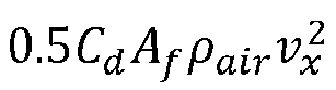
- the terms 0.5 C d A f ⁇ air v x 2 and gC r m GCW must be overcome by the propulsion MSDs, while in downhill scenarios the terms instead help to brake the vehicle 100.
- the electric machine must be dimensioned to support positive torque sufficient for use cases 1110 and 1120, while the combination of the eddy current braking device and the electric machine must be dimensioned to provide a combined negative torque to support use cases 1130 and hard braking according to use case 1140.
- the vehicle 100 will, most likely, comprise several electric machines and eddy current braking devices which will be coordinated to meet torque requirements.
- the electric power used to generate the electric current in the conductive coil may be regenerated electric power from the electric machine 230, 280.
- the electric power used to generate the electric current could also come from an energy storage device such as a battery or a super-capacitor.
- An electrical energy absorption device 250, 310, 320 can for example be a device that stores electrical energy, such as a rechargeable battery 310 or a super-capacitor.
- An electrical energy absorption device 250, 310, 320 can also be a device that dissipates electrical energy, such as a resistor 320 which converts the electrical energy to heat without providing any useful effect such as braking or energy storage.
- An electrical energy absorption device 250, 310, 320 may also be a combination of devices that store electrical energy and devices that dissipate electrical energy.
- FIG. 3 further illustrates the braking arrangement described above from a functional perspective.
- the control unit 210 is arranged to send a braking request to the electric machine 230, 280 via a communication interface 330.
- the electric machine 230, 280 generates electric power which is transmitted to the distribution network 260 via a power interface 340.
- the distribution network is arranged to distribute the generated electric power between the eddy current braking device 240, 290 and an energy absorption device 250, 310, 320 over two respective power distribution interfaces 360, 370 in dependence of input received from the control unit 210 over a control interface 350.
- the control unit 210 is arranged to obtain an energy absorption capability of the energy absorption device 250, 310, 320 over interface 380 and a braking and energy dissipation capacity of the eddy current braking device 240, 290 over interface 390, and modify the input to the distribution network 260 in dependence of these parameters.
- the corresponding required negative torque may exceed what can be generated by the electric machine 230, 280 alone.
- a larger fraction of the regenerated electric power may then be directed to the eddy current braking device 240, 290, which will in turn generate a negative torque, resulting in a larger total negative torque than that produced by the electric machine 230, 290 alone. This way a very strong braking force can be generated, which is an advantage.
- a larger fraction of the regenerated electric power may be directed to the eddy current braking device 240, 290 even if the required torque could be produced solely by the electric machine 230, 280.
- Directing the regenerated electric power to the eddy current braking device 240, 290 will result in an additional negative torque being generated by the eddy current braking device 240, 290. This serves both to dissipate the excess regenerated electric power and to decrease the negative torque that needs to be produced by the electric machine 230, 280, resulting in less electric power being regenerated. This way the specification and requirements imposed on the peak energy absorption capability of the energy absorption device can be relaxed, which is an advantage.
- control unit 210 may be configured to control the distribution of regenerated electrical power from the electric machine 230, 280 between the energy absorption device 250, 310, 320 and the eddy current braking device 240, 290 in dependence of an energy absorption capability of the energy absorption device 250, 310, 320.
- An energy absorption capability of the energy absorption device 250, 310, 320 may indicate a maximum amount of energy that the energy absorption device 250, 310, 320 can absorb without sustaining damage.
- An energy absorption capability of an energy absorption device 250, 310, 320 may also indicate a maximum rate of energy absorption by the energy absorption device 250, 310, 320, or a combination of a maximum amount of energy that can be absorbed and a maximum rate at which it can be absorbed.
- an energy absorption capability may be determined by the difference between the current state of charge of the battery 310 and the maximum charge of the battery 310.
- an energy absorption capability may be determined by the power rating of the resistor 320, i.e. the amount of power that can be dissipated via the resistor 320 without causing it to overheat or become damaged. It is appreciated that the energy absorption capability of a device can vary over time, both short-term and long-term. For instance, an already overheated resistor will have a smaller energy absorption capability compared to a cool un-used resistor, causing variation over time-spans such as tens of minutes or even tens of seconds. A new battery often has better energy absorption capabilities compared to an older more worn battery, thus the energy absorption capability may also range over a time span of months or even years.
- the energy absorption device may comprise a rechargeable battery 310
- the control unit 210 may be configured to control the distribution of regenerated electrical power from the electric machine 230, 280 between the rechargeable battery 310 and the eddy current braking device 240, 290 in dependence of a state of charge, SOC, of the rechargeable battery 310.
- SOC state of charge
- a larger fraction of the regenerated electrical power may be directed to the rechargeable battery 310 if the state of charge, SOC, is low.
- a larger fraction of the regenerated electrical power may be directed to the eddy current braking device 240, 290.
- the energy absorption device may comprise a resistor 320 configured to dissipate excess electrical energy from the electric machine 230, 280 and to regulate a voltage level of the braking arrangement. That is, the electrical resistance of the resistor 320 may be selected such that a voltage experienced by other components of the braking arrangement, e.g. the eddy current braking device 240, 290 or the energy absorption device 250, 310, 320, is kept at a desired value.
- the braking torque capability level Tcap of the electric machine 230, 280 may generally correspond to a torque level that is sustainable over an extended period of time.
- An extended period of time could in this context be 60 seconds or more.
- a sustainable torque level may e.g. depend on a capacity of the cooling system of the electric machine 230, 280.
- the electric machine 230, 280 is also normally associated with a peak braking torque level Tpeak above a braking torque capability level of the electric machine.
- This peak braking torque level can be maintained by the electric machine for a limited duration of time.
- the control unit 210 may then be configured to request a braking torque level from the electric machine 230, 280 between the peak braking torque level and the braking torque capability level to decelerate the heavy duty vehicle.
- a limited duration of time could for example be 30 seconds or less.
- the control unit may be arranged to distribute the additional electric power to the eddy current braking device 240, 290.
- a braking torque will then be generated by the eddy current braking device, resulting in a high total braking torque.
- the total peak braking torque Tpeak may approach four times the total continuous maximum braking torque of the electric machine, though only for the limited amount of time during which a braking torque above Tcap can be sustained. This may for example be useful for emergency braking.
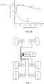
- Figure 4 comprises a graph 400 illustrating braking torque as a function of the angular velocity of the wheel axle 540.
- braking torques up to the braking torque capability level Tcap can be applied for an extended period of time, and braking torques up to the peak braking torque level Tpeak can be applied for a limited time.
- the electric machine 230, 280 may become unable to sustain the braking torque, leading to a decrease in braking torque with increasing angular velocity as seen in Figure 4 .
- the braking arrangement 200, 300 may be arranged to power the eddy current braking device 240, 290 from a different energy source at high angular velocities of the wheel axle 540.
- This energy source may for example be a battery 320 or a super-capacitor.
- the braking arrangement 200, 300 may also be arranged to power the eddy current braking device from a different energy source if the function of the electric machine 230, 280 becomes impaired.
- control unit 210 may be arranged to perform a vehicle motion management function comprising force generation and motion support device, MSD, coordination.
- FIG. 6A schematically illustrates functionality 600 for controlling a wheel 220 by some example motion support device (MSDs) here comprising the electric machine 230 and the eddy current brake 240.
- the control is based on, e.g., measurement data obtained from vehicle sensors 690 such as wheel speed sensors, global positioning system (GPS) sensors, radar sensors, lidar sensors, and also vision based sensors such as camera sensors and infra-red detectors.
- vehicle sensors 690 such as wheel speed sensors, global positioning system (GPS) sensors, radar sensors, lidar sensors, and also vision based sensors such as camera sensors and infra-red detectors.
- GPS global positioning system
- FIG. 7 An example vehicle motion support device control system is also shown in Figure 7 .
- a traffic situation management (TSM) function 610 plans driving operation with a time horizon of, e.g., 10 seconds or so. This time frame corresponds to, e.g., the time it takes for the vehicle 100 to negotiate a curve.
- the vehicle maneuvers, planned and executed by the TSM can be associated with acceleration profiles a req and curvature profiles c req which describe a desired vehicle velocity and turning for a given maneuver.
- the TSM function 610 continuously requests the desired acceleration profiles a req and curvature profiles c req from a vehicle motion management (VMM) function 620 which performs force allocation to meet the requests from the TSM in a safe and robust manner.
- VMM function continuously feeds back capability information to the TSM function detailing the current capability of the vehicle in terms of, e.g., forces, maximum velocities, and accelerations which can be generated.
- Acceleration profiles and curvature profiles may also be obtained from a driver of the heavy duty vehicle via normal control input devices such as a steering wheel, accelerator pedal and brake pedal.
- the source of said acceleration profiles and curvature profiles is not within scope of the present disclosure and will therefore not be discussed in more detail herein.
- the VMM function 620 operates with a time horizon of about 1 second or so, and continuously transforms the acceleration profiles a req and curvature profiles c req into control commands for controlling vehicle motion functions, actuated by the different MSDs 230, 240 of the vehicle 100 which in turn report back capabilities to the VMM function 620.
- the different capabilities are used by the VMM function as constraints in the vehicle control.
- the VMM function 620 performs vehicle state or motion estimation 630, i.e., the VMM function 620 continuously determines a vehicle state s comprising positions, speeds, accelerations and articulation angles of the different units in the vehicle combination by monitoring operations using various sensors 690 arranged on the vehicle 100, often but not always in connection to the MSDs.
- the required global force vector V is input to an MSD coordination function 650 which allocates wheel forces and also coordinates other MSDs such as steering and suspension.
- the coordinated MSDs then together provide the desired lateral Fy and longitudinal Fx forces on the vehicle units, as well as the required moments Mz, to obtain the desired motion by the vehicle combination 100.
- vehicle unit motion By determining vehicle unit motion using, e.g., global positioning systems, vision-based sensors, wheel speed sensors, radar sensors and/or lidar sensors, and translating this vehicle unit motion into a local coordinate system of a given wheel 220 (in terms of, e.g., longitudinal and lateral velocity components), it becomes possible to accurately estimate wheel slip in real time by comparing the vehicle unit motion in the wheel reference coordinate system to data obtained from the wheel speed sensor arranged in connection to the wheel 220.
- a local coordinate system of a given wheel 220 in terms of, e.g., longitudinal and lateral velocity components
- a tyre model can be used to translate between a desired longitudinal tyre force Fx i for a given wheel i and an equivalent wheel slip ⁇ i for the wheel.
- Wheel slip ⁇ relates to a difference between wheel rotational velocity and speed over ground and will be discussed in more detail below.
- Wheel speed ⁇ is a rotational speed of the wheel, given in units of, e.g., rotations per minute (rpm) or angular velocity in terms radians/second (rad/sec) or degrees/second (deg/sec).
- a tyre model is a model of wheel behavior which describes wheel force generated in longitudinal direction (in the rolling direction) and/or lateral direction (orthogonal to the longitudinal direction) as function of wheel slip.
- Tyre and vehicle dynamics Elsevier Ltd. 2012, ISBN 978-0-08-097016-5, Hans Pacejka covers the fundamentals of tyre models. See, e.g., chapter 7 where the relationship between wheel slip and longitudinal force is discussed.
- the VMM function 620 manages both force generation and MSD coordination, i.e., it determines what forces that are required at the vehicle units in order to fulfil the requests from the TSM function 610, for instance to accelerate the vehicle according to a requested acceleration profile requested by TSM and/or to generate a certain curvature motion by the vehicle also requested by TSM.
- the forces may comprise e.g., yaw moments Mz, longitudinal forces Fx and lateral forces Fy, as well as different types of torques to be applied at different wheels.
- the VMM function 620 keeps track of the state of charge of the electrical energy system (ESS) of the vehicle, i.e., the traction batteries or the fuel cell system as well as the current state of any brake resistors, and determines how to best meet braking torque requirements by the electric machines and by the eddy current braking devices.
- the VMM directs electrical energy to the eddy current brakes if this is favorable in a given situation, and to the ESS otherwise.
- the inverse tyre model block 660 translates the required wheel forces Fx i , Fy i determined for each wheel, or for a subset of wheels, by the MSD coordination block 650 into equivalent wheel speeds ⁇ wi or wheel slips ⁇ i . These wheel speeds or slips are then sent to the respective MSD controllers 680.
- the MSD controllers report back capabilities 671-673 which can be used as constraints in, e.g., the MSD coordination block 650.
- ⁇ is bounded between -1 and 1 and quantifies how much the wheel is slipping with respect to the road surface.
- Wheel slip is, in essence, a speed difference measured between the wheel and the vehicle.
- the herein disclosed techniques can be adapted for use with any type of wheel slip definition. It is also appreciated that a wheel slip value is equivalent to a wheel speed value given a velocity of the wheel over the surface, in the coordinate system of the wheel.
- a tyre 220 is subject to a longitudinal force F x , a lateral force F y , and a normal force F z .
- the normal force F z is key to determining some important vehicle properties. For instance, the normal force to a large extent determines the achievable lateral tyre force F y by the wheel since, normally, F y ⁇ ⁇ F z , where ⁇ is a friction coefficient associated with a road friction condition.
- the maximum available lateral force for a given lateral slip can be described by the so-called Magic Formula as described in " Tyre and vehicle dynamics", Elsevier Ltd. 2012, ISBN 978-0-08-097016-5, by Hans Pacejka .
- slip control during endurance braking can be improved by simultaneously using several types of braking, i.e. what is known as brake blending.
- the control unit 210 may be configured to control the distribution of regenerated electrical power from the electric machine 230, 280 between the energy absorption device 250, 310, 320 and the eddy current braking device 240, 290 such that a constant baseline torque level is generated by the eddy current braking device 240, 290.
- the torque applied by the electric machine can then be modulated to control wheel slip at a desired wheel slip level.
- the electric machine 230, 280 can be used to control wheel slip with low latency.
- Vehicle downhill gradeability relates to the ability of a heavy duty vehicle to drive down long hills at constant cruising speed.
- the air resistance and the rolling resistance from the road decelerates the vehicle, while the gravitational pull on the vehicle provides accelerating force.
- a retarder or engine brake is used to provide endurance braking.
- the disclosed braking arrangements are possible to design so the endurance braking is supported without need for additional retarders, friction brakes, or the like.
- the eddy current braking device and the electric machine are dimensioned to support a constant cruising speed, e.g., somewhere between 80-110 km/h, during extended downhill driving.
- a constant cruising speed e.g., somewhere between 80-110 km/h
- the electric machine is dimensioned to provide a continuous negative torque level at a given level and also arranged to distribute the regenerated energy to the eddy current braking device when the energy absorption capability of the energy absorption device is depleted.
- the eddy current braking device is dimensioned to absorb this energy level.
- the electric machine 230, 280, the eddy current braking device 240, 290, and the power distribution network 260 may be integrally formed in a single wheel end module.
- a wheel end module may comprise an output port for feeding electrical energy to the energy absorption device 250, 310, 320.
- the wheel end module may also comprise a control port by which it can be connected to the control unit 210.
- the control unit 210 may then be arranged to send e.g. a torque request or a wheel slip request as described above to the wheel end module together with an energy absorption capability of an energy absorption device 250, 310, 320 that is external to the wheel end module.
- the requested torque or wheel slip can then be generated by the electric machine 230, 280 and the eddy current braking device 240, 290 in such a way that the electrical energy fed to the energy absorption device 250, 310, 320 does not exceed the energy absorption capability.
- the electric machine 230, 280 may be an axial flux electric machine.
- the stator forms a substantially cylindrical shell concentric with the substantially circular rotor and the magnetic flux is directed radially between the rotational axis of the rotor and the stator
- the magnetic flux in an axial flux electric machine is directed along the rotational axis of the rotor.
- Both the rotor and the stator in an axial flux electric machine may be thought of as discs, placed next to each other with the axis of rotation of the rotor perpendicular to both discs.
- the magnetic flux between rotor and stator will then be parallel to the axis of rotation.
- more than one stator may be used.
- Axial flux electric machines may be associated with higher power densities and a less complicated manufacturing process compared to radial flux electric motors.
- a heavy duty vehicle unit 110, 120, 130, 140 comprising a braking arrangement 200, 300 as described above.
- the flowchart in Figure 8 shows a method, performed by a control unit 210, for decelerating a heavy duty vehicle 100.
- the method comprises obtaining S1 a deceleration request indicative of a desired braking torque and determining S2 if regenerative braking by an electric machine 230, 280 associated with a braking torque capability is sufficient to meet the deceleration request.
- the method further comprises applying S3 a braking torque by a combination of the electric machine 230, 280 and an eddy current braking device 240, 290 powered by the electric machine 230, 280 if the regenerative braking capability of the electric machine 230, 280 is not sufficient to meet the deceleration request.
- a deceleration request may be obtained from a traffic situation management (TSM) function as described above.
- the deceleration request may be obtained via pedal inputs from the driver.
- TSM traffic situation management
- the eddy current braking device 240, 290 may be powered directly by the electric machine 230, 280. That is, as regenerative braking by the electric machine 230, 280 results in the generation of electric power, some of this electric power is directed to power the conductive coil of the electromagnet comprised n the eddy current braking device 240, 290.
- the method may also comprise controlling S4 the electric machine 230, 280 to generate a braking torque above the braking capability of the electric machine for a limited duration of time to meet the deceleration request.
- the additional electrical power generated during this time can be used to directly power the eddy current braking device 240, 290, which results in a substantial increase of the total braking torque.
- the method may also comprise that the braking capability of the electric machine 230, 280 is determined S21 in dependence of an energy absorption capability of an energy absorption device 250, 310, 320.
- An energy absorption device 250, 310, 320 may be a device that dissipates electric energy into heat, such as a resistor 320, or a device that stores electric energy, such as a battery 310.
- An energy absorption capability of a resistor 320 may be determined by its power rating, i.e. how much power it can dissipate without overheating or sustaining damage.
- the energy absorption capability of a battery 310 may be determined by a difference between the current state of charge of the battery 310 and the maximum charge.
- the energy absorption capability of the energy absorption device is large, e.g. if the state of charge of the battery 310 is low, it can absorb a larger amount of regenerated electric power from the electric machine 230, 280 and the braking capability may thus be higher. If the battery is close to its maximum charge, the braking capability may be lower as the regenerated electric power cannot be absorbed by the battery 310.
- control unit 210 comprising processing circuitry 910 configured to perform a method as described above, and a computer program 1020 comprising program code means for performing a method as previously described when said program is run on a computer or on processing circuitry 910 of a control unit (210.
- FIG. 9 schematically illustrates, in terms of a number of functional units, the components of a control unit 210 according to embodiments of the discussions and methods disclosed herein.
- This control unit 210 may be comprised in a vehicle unit 110, 120, 130, e.g., in the form of a vehicle motion management (VMM) unit configured to perform force allocation and the like.
- VMM vehicle motion management
- Processing circuitry 910 is provided using any combination of one or more of a suitable central processing unit CPU, multiprocessor, microcontroller, digital signal processor DSP, etc., capable of executing software instructions stored in a computer program product, e.g. in the form of a storage medium 930.
- the processing circuitry 910 may further be provided as at least one application specific integrated circuit ASIC, or field programmable gate array FPGA.
- the processing circuitry 910 is configured to cause the control unit 210 to perform a set of operations, or steps, such as the methods discussed in connection to Figure 8 .
- the storage medium 930 may store the set of operations
- the processing circuitry 910 may be configured to retrieve the set of operations from the storage medium 930 to cause the control unit 210 to perform the set of operations.
- the set of operations may be provided as a set of executable instructions.
- the processing circuitry 910 is thereby arranged to execute methods as herein disclosed.
- the storage medium 930 may also comprise persistent storage, which, for example, can be any single one or combination of magnetic memory, optical memory, solid state memory or even remotely mounted memory.
- the control unit 210 may further comprise an interface 920 for communications with at least one external device, such as an electric machine or a gearbox.
- the interface 920 may comprise one or more transmitters and receivers, comprising analogue and digital components and a suitable number of ports for wireline or wireless communication.
- the processing circuitry 910 controls the general operation of the control unit 210, e.g., by sending data and control signals to the interface 920 and the storage medium 930, by receiving data and reports from the interface 920, and by retrieving data and instructions from the storage medium 930.
- Other components, as well as the related functionality, of the control node are omitted in order not to obscure the concepts presented herein.
- Figure 10 illustrates a computer readable medium 1010 carrying a computer program comprising program code means 1020 for performing, e.g., the methods illustrated in Figure 8 , when said program product is run on a computer.
- the computer readable medium and the code means may together form a computer program product 1000.
Landscapes
- Engineering & Computer Science (AREA)
- Transportation (AREA)
- Mechanical Engineering (AREA)
- Power Engineering (AREA)
- Sustainable Energy (AREA)
- Sustainable Development (AREA)
- Life Sciences & Earth Sciences (AREA)
- Chemical & Material Sciences (AREA)
- Combustion & Propulsion (AREA)
- Microelectronics & Electronic Packaging (AREA)
- Physics & Mathematics (AREA)
- Fluid Mechanics (AREA)
- Electric Propulsion And Braking For Vehicles (AREA)
Description
- The present disclosure relates to heavy-duty vehicles such as semi-trailer vehicles for cargo transport, and in particular to arrangements for decelerating the heavy duty vehicle based on combinations of electrical braking devices. Although the invention will be described mainly with respect to semi-trailer vehicles and trucks, the invention is not restricted to this particular type of vehicle but may also be used in other types of vehicles.
- A heavy-duty vehicle, such as a truck or semi-trailer vehicle, normally comprises a service brake system based on friction brakes. Friction brakes such as disc brakes or drum brakes are not capable of prolonged periods of use which may occur when driving downhill for an extended period of time. If the friction brakes are used too intensively, a phenomenon referred to as brake fading may occur. Brake fading is caused by a build-up of heat in the braking surfaces and leads to significantly reduced braking capability. To avoid brake fading, heavy duty vehicles often comprise auxiliary brakes capable of endurance braking, such as engine brakes and various retarder systems.
- Electric machines can also be used to brake a vehicle, i.e., to generate braking torque. The electric machine then acts as a generator which converts the kinetic energy from the vehicle into electrical energy. This electrical energy can be fed to a rechargeable battery, or to a brake resistor which dissipates the electrical energy as heat. Electrical machines are normally associated with a limited braking torque capability, and the energy dissipation capability is limited. An other example of prior art
US 2020/317060 . -
WO 2013/186158 discloses a type of vehicle brake arrangement based on a combination of an electric machine and an eddy current brake. This arrangement is able to generate more torque compared to the electric machine alone. -
WO 2020/317060 discloses a vehicle braking system comprising an eddy current braking device arranged to receive current from an electrical machine arranged for regenerative braking, and a controller means arranged to control the amount of current to be provided to the eddy current braking device and the amount of current to be provided to an energy storage means in dependence of at target deceleration value of the vehicle and an energy absorption capability of the energy storage means. -
WO 2013/186158 discloses a wheel drive unit comprising an electric machine and an eddy current brake, wherein both the electric machine and the eddy current brake can be used for braking. - However, there is a continuing need for further improvements in braking arrangements for heavy duty vehicles which are able to provide sufficient braking torque, also for extended periods of time, which are not susceptible to brake fading.
- The present invention is defined by the attached independent claims. Other preferred embodiments may be found in the dependent claims.The present application discloses a braking arrangement (200, 300) for decelerating a heavy duty vehicle (100), the arrangement comprising a control unit (210), at least one electric machine (230, 280) arranged for regenerative braking, an electrical energy absorption device (250, 310, 320), an eddy current braking device (240, 290), and a power distribution network (260) arranged to connect the electric machine (230, 280) to the energy absorption device (250, 310, 320) and to the eddy current braking device (240, 290), wherein the control unit (260) is configured to distribute regenerated electrical power from the electric machine (230, 280) between the energy absorption device (250, 310, 320) and the eddy current braking device (240, 290) by the power distribution network (260) in dependence of a target deceleration value of the heavy duty vehicle (100), wherein the control unit (210) is also configured to control the distribution of regenerated electrical power from the electric machine (230, 280) between the energy absorption device (250, 310, 320) and the eddy current braking device (240, 290) in dependence of an energy absorption capability of the energy absorption device (250, 310, 320), characterized in that the control unit (210) is configured to control the distribution of regenerated electrical power from the electric machine (230, 280) between the energy absorption device (250, 310, 320) and the eddy current braking device (240, 290) such that a constant baseline torque level is generated by the eddy current braking device, the torque applied by the electric machine being modulated to control wheel slip at a desired wheel slip level. Furthermore the present application discloses a method performed by a control unit (210) for decelerating a heavy duty vehicle (100), the method comprising obtaining (S1) a deceleration request indicative of a desired braking torque, determining (S2) if regenerative braking by an electric machine (230, 280) associated with a braking torque capability is sufficient to meet the deceleration request, applying (S3) braking torque by a combination of the electric machine (230, 280) and an eddy current braking device (240, 290) powered by the electric machine (230, 280) if the regenerative braking capability of the electric machine (230, 280) is not sufficient to meet the deceleration request, and distributing the regenerated electrical power produced by the regenerative braking capability between an energy absorption device (250, 310, 320) and the eddy current braking device (240, 290) such that a constant baseline torque level is generated by the eddy current braking device, the torque applied by the electric machine being modulated to control wheel slip at a desired wheel slip level.
- With reference to the appended drawings, below follows a more detailed description of embodiments of the invention cited as examples. In the drawings:
- Figure 1
- shows an example vehicle combination comprising a dolly vehicle unit;
- Figure 2
- illustrates an example braking arrangement for braking a vehicle unit;
- Figure 3
- is a functional view of a braking arrangement;
- Figure 4
- is a graph illustrating an example of torque vs wheel axle speed;
- Figure 5
- shows an eddy current brake comprising a plurality of conductive discs;
- Figure 6A
- schematically illustrates functions of a vehicle control system;
- Figure 6B
- is a graph of an example relationship between wheel force and wheel slip;
- Figure 7
- shows a vehicle motion support device control system;
- Figure 8
- is a flow chart illustrating a method;
- Figure 9
- schematically illustrates a control unit;
- Figure 10
- shows an example computer program product; and
- Figure 11
- illustrates some example heavy duty vehicle use cases.
- The invention will now be described more fully hereinafter with reference to the accompanying drawings, in which certain aspects of the invention are shown. This invention may, however, be embodied in many different forms and should not be construed as limited to the embodiments and aspects set forth herein; rather, these embodiments are provided by way of example so that this disclosure will be thorough and complete, and will fully convey the scope of the invention to those skilled in the art. Like numbers refer to like elements throughout the description.
- It is to be understood that the present invention is not limited to the embodiments described herein and illustrated in the drawings; rather, the skilled person will recognize that many changes and modifications may be made within the scope of the appended claims.
-
Figure 1 illustrates anexample vehicle combination 100 for cargo transport. Thevehicle combination 100 comprises a truck ortowing vehicle 110 configured to tow afirst trailer unit 120 in a known manner, e.g., by afifth wheel connection 115. To extend the cargo transport capability of thevehicle combination 100, adolly vehicle 130 can be connected to the rear of thefirst trailer 120 via a drawbar. This dolly vehicle can then tow asecond trailer 140, thus increasing the cargo transport capacity of the vehicle combination. - Each of the
vehicle units vehicle combination 100. - A
dolly vehicle 130 is traditionally a passive vehicle comprising no driven or steerable axles, and with a relatively short wheelbase. It has recently been shown that self-powered dolly vehicles may provide both increased fuel efficiency and maneuverability. This type of self-powered dolly vehicle comprises an on-board energy source, such as a battery, super-capacitor or a fuel cell stack, and at least one pair of driven wheels. Some self-powered dolly vehicles may also be steerable. - Both the
truck 110 and the self-poweredsteerable dolly vehicle 130, and potentially also one or more of thetrailer units vehicle 100 therefore normally comprises friction brakes to complement the regenerative braking by the electric machine. - However, as mentioned above, it is required to be able to brake the
vehicle 100 as it travels down steep long hills and the like, where friction brakes risk onset of brake fading. Thus, an endurance braking system, such as an engine brake or hydraulic brake system for prolonged periods of braking may be required in addition to the regenerative brakes and the friction brakes. This rather complicated braking system drives cost and also requires extensive servicing. - It is most advantageous to be able to generate high braking torque by a self-powered dolly vehicle unit. This is because the
dolly vehicle unit 130 can act as an anchor to brake theheavy duty vehicle 100, and also to reduce overshoot by thesecond trailer 140 during hard turning, e.g., during evasive maneuvering. Thus, the techniques disclosed herein are particularly suitable for use with self-powereddolly vehicle units 130. - It is appreciated that the techniques and devices disclosed herein can be applied together with a wide variety of electrically powered vehicle units, not just those exemplified in
Figure 1 . -
Figure 2 shows abraking arrangement 200 for decelerating aheavy duty vehicle 100. The arrangement comprises acontrol unit 210 and least oneelectric machine energy absorption device 250, an eddycurrent braking device power distribution network 260 arranged to connect theelectric machine energy absorption device 250, and to the eddycurrent braking device control unit 210 is configured to distribute regenerated electrical power from theelectric machine energy absorption device 250 and the eddycurrent braking device power distribution network 260 in dependence of a target deceleration value of theheavy duty vehicle 100. - Herein, a heavy-
duty vehicle 100 is taken to be a vehicle designed for the handling and transport of heavier objects or large quantities of cargo. As an example, a heavy-duty vehicle could be a semi-trailer vehicle or a truck as described above. As another example, a heavy-duty vehicle could be a vehicle designed for use in construction, mining operations, and the like. - The
control unit 210 can also be configured to control various functions in addition to power distribution, such as steering. It may be equipped with acommunication interface 265 arranged for communication with other units comprised in thevehicle 100. This control unit will be discussed in more detail below in connection toFigure 9 . - The
electric machine wheel 220. To achieve deceleration of the vehicle, a negative torque T1l, T1r, T2l, T2r may be generated by theelectric machine current braking device - With reference also to
Figure 5 , an eddycurrent braking device conductive component 510, which may be in the shape of a disc, and at least onemagnet current braking device conductive discs 510 attached to awheel axle 540 for generating braking torque.Figure 5 shows an example of such an eddy current braking device with a plurality of electricallyconductive discs 510. However, a single disc is of course sufficient for generating braking torque by the eddy current braking device. More than one magnet can of course also be used with one or more respective electrically conductive discs. - The electrically conductive discs are made from an electrically conductive material, which is herein considered to be a material with an electric conductivity similar to that of a metal, substantially an electric conductivity above 100000 Siemens / m. Optionally, the electrically conducting material may be a metal that reacts weakly to magnetic fields, such as copper or aluminum.
- The electrically conductive disc or
discs 510 are arranged such that when anaxle 540 to which the eddycurrent braking device discs 510 are also rotating. This may for example be accomplished by attaching theconductive disc 510 directly to theaxle 540, or via some form of gear arrangement. - The at least one
magnet - The at least one
magnet electrically conducting disc 510 is exposed to the magnetic field between the two magnetic poles, with the field lines of the magnetic field substantially perpendicular to the surface of thedisc 510. As an example, themagnet conductive disc 510 could be inserted into an air gap of the magnetic circuit. As another example, twomagnets conductive disc 510 inserted between the north and south pole. - When the
axle 540 is rotating and the eddycurrent braking device magnet conductive disc 510 as predicted by Faraday's law of induction. Said eddy currents generate a magnetic field that counteracts the magnetic field generated by the magnet, thereby creating a drag force on theelectrically conducting disc 510. The electrons forming part of the induced eddy currents are subject to an electrical resistance when moving through the electricallyconductive disc 510, causing some of the energy of the moving electrons to be dissipated as heat. Through this mechanism, the kinetic energy of the electricallyconductive disc 510 is converted into heat. - When the eddy
current braking device conductive disc 510 is not exposed to a magnetic field from themagnet magnet current braking device -
Figure 11 illustrates fouruse cases 1100 which aheavy duty vehicle 100 must be able to operate in. Thevehicle 100 must be able to start in slopes 1110 (startability), even if thevehicle 100 is heavily loaded and the road friction is not ideal. The vehicle must also be able to negotiate even steeper slopes atconstant velocity 1120, e.g., 70 km/h (positive gradeability).Downhill gradeability performance 1130 is perhaps even more important, which means that thevehicle 100 must be able to limit speed when driving downhill for longer distances (endurance braking). Finally, acceleration and braking capability implies that peak torque requirements, both on positive and on negative torque, must be met by the vehicle MSDs. - The required longitudinal torque can be expressed as

use cases - In uphill driving positive torque scenarios, the terms
vehicle 100. This means that the electric machine must be dimensioned to support positive torque sufficient foruse cases use cases 1130 and hard braking according touse case 1140. - It is appreciated that the
vehicle 100 will, most likely, comprise several electric machines and eddy current braking devices which will be coordinated to meet torque requirements. - As previously described, the electric power used to generate the electric current in the conductive coil may be regenerated electric power from the
electric machine - However, the electric power used to generate the electric current could also come from an energy storage device such as a battery or a super-capacitor.
- An electrical
energy absorption device rechargeable battery 310 or a super-capacitor. An electricalenergy absorption device resistor 320 which converts the electrical energy to heat without providing any useful effect such as braking or energy storage. An electricalenergy absorption device -
Figure 3 further illustrates the braking arrangement described above from a functional perspective. Thecontrol unit 210 is arranged to send a braking request to theelectric machine communication interface 330. During regenerative braking, theelectric machine distribution network 260 via apower interface 340. - The distribution network is arranged to distribute the generated electric power between the eddy
current braking device energy absorption device control unit 210 over acontrol interface 350. Thecontrol unit 210 is arranged to obtain an energy absorption capability of theenergy absorption device interface 380 and a braking and energy dissipation capacity of the eddycurrent braking device interface 390, and modify the input to thedistribution network 260 in dependence of these parameters. - As an example, if a large deceleration value of the
vehicle 100 is required, the corresponding required negative torque may exceed what can be generated by theelectric machine current braking device electric machine - As another example, if the capacity of the
energy absorption device current braking device electric machine current braking device current braking device electric machine - Thus, the
control unit 210 may be configured to control the distribution of regenerated electrical power from theelectric machine energy absorption device current braking device energy absorption device - An energy absorption capability of the
energy absorption device energy absorption device energy absorption device energy absorption device - For a
battery 310, an energy absorption capability may be determined by the difference between the current state of charge of thebattery 310 and the maximum charge of thebattery 310. For aresistor 320, an energy absorption capability may be determined by the power rating of theresistor 320, i.e. the amount of power that can be dissipated via theresistor 320 without causing it to overheat or become damaged. It is appreciated that the energy absorption capability of a device can vary over time, both short-term and long-term. For instance, an already overheated resistor will have a smaller energy absorption capability compared to a cool un-used resistor, causing variation over time-spans such as tens of minutes or even tens of seconds. A new battery often has better energy absorption capabilities compared to an older more worn battery, thus the energy absorption capability may also range over a time span of months or even years. - The energy absorption device may comprise a
rechargeable battery 310, and thecontrol unit 210 may configured to control the distribution of regenerated electrical power from theelectric machine rechargeable battery 310 and the eddycurrent braking device rechargeable battery 310. In particular, a larger fraction of the regenerated electrical power may be directed to therechargeable battery 310 if the state of charge, SOC, is low. Conversely, if the state of charge, SOC, is high or the battery is fully charged, a larger fraction of the regenerated electrical power may be directed to the eddycurrent braking device - Also, the energy absorption device may comprise a
resistor 320 configured to dissipate excess electrical energy from theelectric machine resistor 320 may be selected such that a voltage experienced by other components of the braking arrangement, e.g. the eddycurrent braking device energy absorption device - With reference to
Figure 4 , the braking torque capability level Tcap of theelectric machine electric machine - However, the
electric machine control unit 210 may then be configured to request a braking torque level from theelectric machine - Applying a braking torque above Tcap will result in the generation of additional electric power. Optionally, the control unit may be arranged to distribute the additional electric power to the eddy
current braking device -
Figure 4 comprises agraph 400 illustrating braking torque as a function of the angular velocity of thewheel axle 540. At low to moderate angular velocities, braking torques up to the braking torque capability level Tcap can be applied for an extended period of time, and braking torques up to the peak braking torque level Tpeak can be applied for a limited time. At high angular velocities, theelectric machine Figure 4 . - A consequence of this decrease is that less electric power is regenerated, meaning that less electric power from the
electric machine current braking device braking arrangement current braking device wheel axle 540. This energy source may for example be abattery 320 or a super-capacitor. According to other aspects, thebraking arrangement electric machine - According to aspects, the
control unit 210 may be arranged to perform a vehicle motion management function comprising force generation and motion support device, MSD, coordination. -
Figure 6A schematically illustratesfunctionality 600 for controlling awheel 220 by some example motion support device (MSDs) here comprising theelectric machine 230 and theeddy current brake 240. The control is based on, e.g., measurement data obtained fromvehicle sensors 690 such as wheel speed sensors, global positioning system (GPS) sensors, radar sensors, lidar sensors, and also vision based sensors such as camera sensors and infra-red detectors. An example vehicle motion support device control system is also shown inFigure 7 . - A traffic situation management (TSM) function 610 plans driving operation with a time horizon of, e.g., 10 seconds or so. This time frame corresponds to, e.g., the time it takes for the
vehicle 100 to negotiate a curve. The vehicle maneuvers, planned and executed by the TSM, can be associated with acceleration profiles areq and curvature profiles creq which describe a desired vehicle velocity and turning for a given maneuver. TheTSM function 610 continuously requests the desired acceleration profiles areq and curvature profiles creq from a vehicle motion management (VMM) function 620 which performs force allocation to meet the requests from the TSM in a safe and robust manner. The VMM function continuously feeds back capability information to the TSM function detailing the current capability of the vehicle in terms of, e.g., forces, maximum velocities, and accelerations which can be generated. - Acceleration profiles and curvature profiles may also be obtained from a driver of the heavy duty vehicle via normal control input devices such as a steering wheel, accelerator pedal and brake pedal. The source of said acceleration profiles and curvature profiles is not within scope of the present disclosure and will therefore not be discussed in more detail herein.
- The
VMM function 620 operates with a time horizon of about 1 second or so, and continuously transforms the acceleration profiles areq and curvature profiles creq into control commands for controlling vehicle motion functions, actuated by thedifferent MSDs vehicle 100 which in turn report back capabilities to theVMM function 620. The different capabilities are used by the VMM function as constraints in the vehicle control. - The
VMM function 620 performs vehicle state ormotion estimation 630, i.e., theVMM function 620 continuously determines a vehicle state s comprising positions, speeds, accelerations and articulation angles of the different units in the vehicle combination by monitoring operations usingvarious sensors 690 arranged on thevehicle 100, often but not always in connection to the MSDs. - The result of the
motion estimation 630, i.e., the estimated vehicle state s, is input to aforce generation module 640 which determines the required global forces and moments Fx Fy Mz, V=[V1, V2, V3], and for the different vehicle units to cause thevehicle 100 to move according to the requested acceleration and curvature profiles areq, creq. The required global force vector V is input to anMSD coordination function 650 which allocates wheel forces and also coordinates other MSDs such as steering and suspension. The coordinated MSDs then together provide the desired lateral Fy and longitudinal Fx forces on the vehicle units, as well as the required moments Mz, to obtain the desired motion by thevehicle combination 100. - By determining vehicle unit motion using, e.g., global positioning systems, vision-based sensors, wheel speed sensors, radar sensors and/or lidar sensors, and translating this vehicle unit motion into a local coordinate system of a given wheel 220 (in terms of, e.g., longitudinal and lateral velocity components), it becomes possible to accurately estimate wheel slip in real time by comparing the vehicle unit motion in the wheel reference coordinate system to data obtained from the wheel speed sensor arranged in connection to the
wheel 220. - A tyre model, exemplified in
Figure 6B , can be used to translate between a desired longitudinal tyre force Fxi for a given wheel i and an equivalent wheel slip λi for the wheel. Wheel slip λ relates to a difference between wheel rotational velocity and speed over ground and will be discussed in more detail below. Wheel speed ω is a rotational speed of the wheel, given in units of, e.g., rotations per minute (rpm) or angular velocity in terms radians/second (rad/sec) or degrees/second (deg/sec). A tyre model is a model of wheel behavior which describes wheel force generated in longitudinal direction (in the rolling direction) and/or lateral direction (orthogonal to the longitudinal direction) as function of wheel slip. In "Tyre and vehicle dynamics", Elsevier Ltd. 2012, ISBN 978-0-08-097016-5, Hans Pacejka covers the fundamentals of tyre models. See, e.g., chapter 7 where the relationship between wheel slip and longitudinal force is discussed. - To summarize, the
VMM function 620 manages both force generation and MSD coordination, i.e., it determines what forces that are required at the vehicle units in order to fulfil the requests from theTSM function 610, for instance to accelerate the vehicle according to a requested acceleration profile requested by TSM and/or to generate a certain curvature motion by the vehicle also requested by TSM. The forces may comprise e.g., yaw moments Mz, longitudinal forces Fx and lateral forces Fy, as well as different types of torques to be applied at different wheels. - For instance, the
VMM function 620 keeps track of the state of charge of the electrical energy system (ESS) of the vehicle, i.e., the traction batteries or the fuel cell system as well as the current state of any brake resistors, and determines how to best meet braking torque requirements by the electric machines and by the eddy current braking devices. The VMM directs electrical energy to the eddy current brakes if this is favorable in a given situation, and to the ESS otherwise. - The interface between VMM and MSDs capable of delivering torque to the vehicle's wheels has, traditionally, been focused on torque based requests to each MSD from the VMM without any consideration towards wheel slip. However, this approach has significant performance limitations. In case a safety critical or excessive slip situation arises, then a relevant safety function (traction control, anti-lock brakes, etc.) operated on a separate control unit normally steps in and requests a torque override in order to bring the slip back into control. The problem with this approach is that since the primary control of the actuator and the slip control of the actuator are allocated to different electronic control units (ECUs), the latencies involved in the communication between them significantly limits the slip control performance. Moreover, the related actuator and slip assumptions made in the two ECUs that are used to achieve the actual slip control can be inconsistent and this in turn can lead to sub-optimal performance.
- Significant benefits can be achieved by instead using a wheel speed or wheel slip based request on the interface between VMM and the MSD controller, thereby shifting the difficult actuator speed control loop to the MSD controllers, which generally operate with a much shorter sample time compared to that of the VMM function. Such an architecture can provide much better disturbance rejection compared to a torque based control interface and thus improves the predictability of the forces generated at the tyre road contact patch.
- With reference to
Figure 6A , the inversetyre model block 660 translates the required wheel forces Fxi, Fyi determined for each wheel, or for a subset of wheels, by theMSD coordination block 650 into equivalent wheel speeds ωwi or wheel slips λi. These wheel speeds or slips are then sent to therespective MSD controllers 680. The MSD controllers report back capabilities 671-673 which can be used as constraints in, e.g., theMSD coordination block 650. - Longitudinal wheel slip λ may, in accordance with SAE J670 (SAE Vehicle Dynamics Standards Committee January 24, 2008) be defined as

- The
VMM 620 and optionally also theMSD control units 680 maintains information on vx (in the reference frame of the wheel), while a wheel speed sensor or the like can be used to determine ωx (the rotational velocity of the wheel). - In order for a wheel (or tyre) to produce a wheel force, slip must occur. For smaller slip values the relationship between slip and generated force are approximately linear, where the proportionality constant is often denoted as the slip stiffness of the tyre. A
tyre 220 is subject to a longitudinal force Fx, a lateral force Fy, and a normal force Fz. The normal force Fz is key to determining some important vehicle properties. For instance, the normal force to a large extent determines the achievable lateral tyre force Fy by the wheel since, normally, Fy ≤ µ Fz, where µ is a friction coefficient associated with a road friction condition. The maximum available lateral force for a given lateral slip can be described by the so-called Magic Formula as described in "Tyre and vehicle dynamics", Elsevier Ltd. 2012, ISBN 978-0-08-097016-5, by Hans Pacejka. - According to aspects, slip control during endurance braking can be improved by simultaneously using several types of braking, i.e. what is known as brake blending. As an example, the
control unit 210 may be configured to control the distribution of regenerated electrical power from theelectric machine energy absorption device current braking device current braking device current braking device electric machine - Vehicle downhill gradeability relates to the ability of a heavy duty vehicle to drive down long hills at constant cruising speed. The air resistance and the rolling resistance from the road decelerates the vehicle, while the gravitational pull on the vehicle provides accelerating force. Normally, a retarder or engine brake is used to provide endurance braking. However, the disclosed braking arrangements are possible to design so the endurance braking is supported without need for additional retarders, friction brakes, or the like.
- To guarantee vehicle downhill gradeability, the eddy current braking device and the electric machine are dimensioned to support a constant cruising speed, e.g., somewhere between 80-110 km/h, during extended downhill driving. To design for downhill gradeability means that the electric machine is dimensioned to provide a continuous negative torque level at a given level and also arranged to distribute the regenerated energy to the eddy current braking device when the energy absorption capability of the energy absorption device is depleted. The eddy current braking device is dimensioned to absorb this energy level. Thus, vehicle downhill gradeability is guaranteed.
- The
electric machine current braking device power distribution network 260 may be integrally formed in a single wheel end module. Such a wheel end module may comprise an output port for feeding electrical energy to theenergy absorption device - The wheel end module may also comprise a control port by which it can be connected to the
control unit 210. Thecontrol unit 210 may then be arranged to send e.g. a torque request or a wheel slip request as described above to the wheel end module together with an energy absorption capability of anenergy absorption device electric machine current braking device energy absorption device - According to aspects, the
electric machine - There is also herein disclosed a heavy
duty vehicle unit braking arrangement - The flowchart in
Figure 8 shows a method, performed by acontrol unit 210, for decelerating aheavy duty vehicle 100. The method comprises obtaining S1 a deceleration request indicative of a desired braking torque and determining S2 if regenerative braking by anelectric machine electric machine current braking device electric machine electric machine - As an example, a deceleration request may be obtained from a traffic situation management (TSM) function as described above. As another example, the deceleration request may be obtained via pedal inputs from the driver.
- When a braking torque is applied using both the
electric machine current braking device current braking device electric machine electric machine current braking device - Using the
electric machine current braking device electric machine electric machine current braking device - The method may also comprise that the braking capability of the
electric machine energy absorption device - An
energy absorption device resistor 320, or a device that stores electric energy, such as abattery 310. An energy absorption capability of aresistor 320 may be determined by its power rating, i.e. how much power it can dissipate without overheating or sustaining damage. The energy absorption capability of abattery 310 may be determined by a difference between the current state of charge of thebattery 310 and the maximum charge. - If the energy absorption capability of the energy absorption device is large, e.g. if the state of charge of the
battery 310 is low, it can absorb a larger amount of regenerated electric power from theelectric machine battery 310. - There is also herein disclosed a
control unit 210 comprisingprocessing circuitry 910 configured to perform a method as described above, and acomputer program 1020 comprising program code means for performing a method as previously described when said program is run on a computer or onprocessing circuitry 910 of a control unit (210. -
Figure 9 schematically illustrates, in terms of a number of functional units, the components of acontrol unit 210 according to embodiments of the discussions and methods disclosed herein. Thiscontrol unit 210 may be comprised in avehicle unit Processing circuitry 910 is provided using any combination of one or more of a suitable central processing unit CPU, multiprocessor, microcontroller, digital signal processor DSP, etc., capable of executing software instructions stored in a computer program product, e.g. in the form of astorage medium 930. Theprocessing circuitry 910 may further be provided as at least one application specific integrated circuit ASIC, or field programmable gate array FPGA. - Particularly, the
processing circuitry 910 is configured to cause thecontrol unit 210 to perform a set of operations, or steps, such as the methods discussed in connection toFigure 8 . For example, thestorage medium 930 may store the set of operations, and theprocessing circuitry 910 may be configured to retrieve the set of operations from thestorage medium 930 to cause thecontrol unit 210 to perform the set of operations. The set of operations may be provided as a set of executable instructions. Thus, theprocessing circuitry 910 is thereby arranged to execute methods as herein disclosed. - The
storage medium 930 may also comprise persistent storage, which, for example, can be any single one or combination of magnetic memory, optical memory, solid state memory or even remotely mounted memory. - The
control unit 210 may further comprise aninterface 920 for communications with at least one external device, such as an electric machine or a gearbox. As such theinterface 920 may comprise one or more transmitters and receivers, comprising analogue and digital components and a suitable number of ports for wireline or wireless communication. - The
processing circuitry 910 controls the general operation of thecontrol unit 210, e.g., by sending data and control signals to theinterface 920 and thestorage medium 930, by receiving data and reports from theinterface 920, and by retrieving data and instructions from thestorage medium 930. Other components, as well as the related functionality, of the control node are omitted in order not to obscure the concepts presented herein. -
Figure 10 illustrates a computer readable medium 1010 carrying a computer program comprising program code means 1020 for performing, e.g., the methods illustrated inFigure 8 , when said program product is run on a computer. The computer readable medium and the code means may together form acomputer program product 1000.
Claims (14)
- A braking arrangement (200, 300) for decelerating a heavy duty vehicle (100), the arrangement comprising a control unit (210), at least one electric machine (230, 280) arranged for regenerative braking, an electrical energy absorption device (250, 310, 320), an eddy current braking device (240, 290), and a power distribution network (260) arranged to connect the electric machine (230, 280) to the energy absorption device (250, 310, 320) and to the eddy current braking device (240, 290), wherein the control unit (260) is configured to distribute regenerated electrical power from the electric machine (230, 280) between the energy absorption device (250, 310, 320) and the eddy current braking device (240, 290) by the power distribution network (260) in dependence of a target deceleration value of the heavy duty vehicle (100), wherein the control unit (210) is also configured to control the distribution of regenerated electrical power from the electric machine (230, 280) between the energy absorption device (250, 310, 320) and the eddy current braking device (240, 290) in dependence of an energy absorption capability of the energy absorption device (250, 310, 320), characterized in that the control unit (210) is configured to control the distribution of regenerated electrical power from the electric machine (230, 280) between the energy absorption device (250, 310, 320) and the eddy current braking device (240, 290) such that a constant baseline torque level is generated by the eddy current braking device, the torque applied by the electric machine being modulated to control wheel slip at a desired wheel slip level.
- The braking arrangement (200, 300) according to any previous claim, wherein the eddy current braking device (240, 290) comprises a plurality of electrically conductive discs (510) attached to a wheel axle (540) for generating braking torque.
- The braking arrangement (200, 300) according to any previous claim, wherein the energy absorption device comprises a rechargeable battery (310), wherein the control unit (210) is configured to control the distribution of regenerated electrical power from the electric machine (230, 280) between the rechargeable battery (310) and the eddy current braking device (240, 290) in dependence of a state of charge, SOC, of the rechargeable battery (310).
- The braking arrangement (200, 300) according to any previous claim, wherein the energy absorption device comprises a resistor (320) configured to dissipate excess electrical energy from the electric machine (230, 280) and to regulate a voltage level of the braking arrangement.
- The braking arrangement (200, 300) according to any previous claim, wherein the electric machine (230, 280) is associated with a peak braking torque level (Tpeak) above a braking torque capability level of the electric machine, which peak braking torque level can be maintained by the electric machine for a limited duration of time, wherein the control unit (210) is configured to request a braking torque level from the electric machine (230, 280) between the peak braking torque level and the braking torque capability level to decelerate the heavy duty vehicle.
- The braking arrangement (200, 300) according to any previous claim, wherein the control unit (210) is arranged to perform a vehicle motion management function comprising force generation and motion support device, MSD, coordination.
- The braking arrangement (200, 300) according to any previous claim, wherein the electric machine (230, 280), the eddy current braking device (240, 290), and the power distribution network (260) is integrally formed in a single wheel end module, wherein the wheel end module comprises an output port for feeding electrical energy to the energy absorption device (250, 310, 320).
- The braking arrangement (200, 300) according to any previous claim, wherein the electric machine (230, 280) is an axial flux electric machine.
- A heavy duty vehicle unit (110, 120, 130, 140) comprising a braking arrangement (200, 300) according to any previous claim.
- A method performed by a control unit (210) for decelerating a heavy duty vehicle (100), the method comprisingobtaining (S1) a deceleration request indicative of a desired braking torque,determining (S2) if regenerative braking by an electric machine (230, 280) associated with a braking torque capability is sufficient to meet the deceleration request,applying (S3) braking torque by a combination of the electric machine (230, 280) and an eddy current braking device (240, 290) powered by the electric machine (230, 280) if the regenerative braking capability of the electric machine (230, 280) is not sufficient to meet the deceleration request, anddistributing the regenerated electrical power produced by the regenerative braking capability between an energy absorption device (250, 310, 320) and the eddy current braking device (240, 290) such that a constant baseline torque level is generated by the eddy current braking device, the torque applied by the electric machine being modulated to control wheel slip at a desired wheel slip level.
- The method according to claim 11, comprising
controlling (S4) the electric machine (230, 280) to generate a braking torque above the braking capability of the electric machine for a limited duration of time to meet the deceleration request. - The method according to claim 11 or 12, wherein the braking capability of the electric machine (230, 280) is determined (S21) in dependence of an energy absorption capability of an energy absorption device (250, 310, 320).
- A control unit (210) comprising processing circuitry (910) configured to perform a method according to any of claims 11 to 13.
- A computer program (1020) comprising program code means for performing a method according to any of claims 11 to 13 when said program is run on a computer or on processing circuitry (910) of a control unit (210).
Applications Claiming Priority (1)
| Application Number | Priority Date | Filing Date | Title |
|---|---|---|---|
| PCT/EP2020/084076 WO2022117176A1 (en) | 2020-12-01 | 2020-12-01 | A braking arrangement for heavy duty vehicles |
Publications (2)
| Publication Number | Publication Date |
|---|---|
| EP4255762A1 EP4255762A1 (en) | 2023-10-11 |
| EP4255762B1 true EP4255762B1 (en) | 2024-09-25 |
Family
ID=73726785
Family Applications (1)
| Application Number | Title | Priority Date | Filing Date |
|---|---|---|---|
| EP20820076.6A Active EP4255762B1 (en) | 2020-12-01 | 2020-12-01 | A braking arrangement for heavy duty vehicles |
Country Status (5)
| Country | Link |
|---|---|
| US (1) | US12459368B2 (en) |
| EP (1) | EP4255762B1 (en) |
| KR (1) | KR20230113750A (en) |
| CN (1) | CN116490392A (en) |
| WO (1) | WO2022117176A1 (en) |
Cited By (1)
| Publication number | Priority date | Publication date | Assignee | Title |
|---|---|---|---|---|
| US12617388B2 (en) * | 2021-12-20 | 2026-05-05 | Volvo Truck Corporation | Predictive heavy-duty vehicle motion management based on environment sensing |
Families Citing this family (6)
| Publication number | Priority date | Publication date | Assignee | Title |
|---|---|---|---|---|
| DE102021201113A1 (en) * | 2021-02-05 | 2022-08-11 | Knorr-Bremse Systeme für Nutzfahrzeuge GmbH | Braking of an electrically powered vehicle |
| WO2022194357A1 (en) * | 2021-03-16 | 2022-09-22 | Volvo Truck Corporation | An electrically powered trailer with an endurance braking function |
| US20240326761A1 (en) * | 2021-07-14 | 2024-10-03 | Stop-In-Time Gmbh | Method for braking a vehicle |
| US12485713B2 (en) * | 2023-03-27 | 2025-12-02 | Geoffrey Beech | Connector apparatus to connect a tow vehicle with a wagon |
| IT202300008907A1 (en) * | 2023-05-04 | 2024-11-04 | Torino Politecnico | ELECTRIC VEHICLE AND ITS CONTROL METHOD |
| CN118046758A (en) * | 2024-04-01 | 2024-05-17 | 吉林大学 | A novel motor braking system and braking force distribution method |
Family Cites Families (14)
| Publication number | Priority date | Publication date | Assignee | Title |
|---|---|---|---|---|
| US1072329A (en) * | 1913-05-03 | 1913-09-02 | John F Green | Stretching device. |
| US7137673B2 (en) * | 2003-06-27 | 2006-11-21 | Visteon Global Technologies, Inc. | Vehicle yaw stability system and method |
| DE102010044655A1 (en) * | 2010-09-08 | 2012-03-08 | Jungheinrich Aktiengesellschaft | Industrial truck with an electric traction drive |
| US8700283B2 (en) * | 2011-12-16 | 2014-04-15 | Caterpillar Inc. | Mining truck and regenerative braking strategy therefor |
| DE102012210130A1 (en) | 2012-06-15 | 2013-12-19 | Siemens Aktiengesellschaft | Wheel drive unit for a wheel of an electrically driven vehicle, vehicle and method for operating a wheel drive unit of a vehicle |
| DE102013205314B4 (en) | 2013-03-26 | 2016-09-29 | Continental Automotive Gmbh | Method for operating a recuperation brake device of a motor vehicle and recuperation brake device for a motor vehicle |
| JP2016165165A (en) * | 2013-07-05 | 2016-09-08 | 日立オートモティブシステムズ株式会社 | Braking control device of electric vehicle |
| DE102014108083B4 (en) * | 2014-06-06 | 2016-05-04 | Deutsches Zentrum für Luft- und Raumfahrt e.V. | Brake control method for a vehicle |
| GB2554337B (en) | 2016-05-25 | 2019-10-02 | Jaguar Land Rover Ltd | Apparatus, system and method for braking |
| CN107618495A (en) | 2017-09-20 | 2018-01-23 | 中国重汽集团济南动力有限公司 | A kind of Multi Axle Drive Vehicle Electro-mechanical brake system and braking method |
| CN108036953B (en) | 2017-12-14 | 2019-08-23 | 燕山大学 | In-wheel motor driving automobile Integrated design and Collaborative Control test platform and implementation method |
| KR102518238B1 (en) * | 2017-12-22 | 2023-04-07 | 현대자동차주식회사 | Methdo for applying coast regenerating torque of vehicle |
| US11820254B2 (en) * | 2018-05-03 | 2023-11-21 | Ford Global Technologies, Llc | Hybrid electric vehicle with torque split regenerative braking |
| US11273713B2 (en) * | 2019-09-19 | 2022-03-15 | Ford Global Technologies, Llc | Regenerative braking/anti-lock braking control system |
-
2020
- 2020-12-01 WO PCT/EP2020/084076 patent/WO2022117176A1/en not_active Ceased
- 2020-12-01 CN CN202080107594.XA patent/CN116490392A/en active Pending
- 2020-12-01 EP EP20820076.6A patent/EP4255762B1/en active Active
- 2020-12-01 KR KR1020237018302A patent/KR20230113750A/en not_active Withdrawn
- 2020-12-01 US US18/038,769 patent/US12459368B2/en active Active
Cited By (1)
| Publication number | Priority date | Publication date | Assignee | Title |
|---|---|---|---|---|
| US12617388B2 (en) * | 2021-12-20 | 2026-05-05 | Volvo Truck Corporation | Predictive heavy-duty vehicle motion management based on environment sensing |
Also Published As
| Publication number | Publication date |
|---|---|
| EP4255762A1 (en) | 2023-10-11 |
| US12459368B2 (en) | 2025-11-04 |
| KR20230113750A (en) | 2023-08-01 |
| US20240017623A1 (en) | 2024-01-18 |
| WO2022117176A1 (en) | 2022-06-09 |
| CN116490392A (en) | 2023-07-25 |
Similar Documents
| Publication | Publication Date | Title |
|---|---|---|
| EP4255762B1 (en) | A braking arrangement for heavy duty vehicles | |
| US12570290B2 (en) | Predictive energy and motion management for multitrailer heavy-duty vehicles | |
| EP4284672B1 (en) | An electrical wheel module for acceleration and braking of a heavy-duty vehicle | |
| CN111252046B (en) | Environmentally friendly vehicle and steep slope descent control method for environmentally friendly vehicle | |
| US12479306B2 (en) | Electrically powered trailer with an endurance braking function | |
| US9156358B2 (en) | Regenerative braking in the presence of an antilock braking system control event | |
| EP4247686B1 (en) | Method for reducing high-speed off-tracking in multi-trailer heavy duty vehicles | |
| CN114454866A (en) | Wheel slip based vehicle motion management for heavy vehicles | |
| US20180093571A1 (en) | Braking torque blending system and method | |
| US12325417B2 (en) | Systems and methods for electric vehicle speed control | |
| EP4320006B1 (en) | Methods and devices for braking of a heavy-duty vehicle | |
| US20200172109A1 (en) | Vehicle having electric motor and driving control method for the same | |
| EP4347302B1 (en) | Energy efficient propulsion based on wheel slip balanced drive | |
| CN114981136A (en) | Method for controlling a vehicle braking system | |
| EP4540108B1 (en) | Method and system for controlling a heavy commercial vehicle in uphill conditions | |
| CN118679087A (en) | System for controlling braking operation of vehicle | |
| US12330534B1 (en) | Supplementing regenerative braking | |
| US20250091582A1 (en) | Heavy-duty vehicle motion support device capability feedback | |
| EP3979223A1 (en) | A coil arrangement, a vehicle, a deceleration system, and a method | |
| CN119773521A (en) | Control method for comfortable braking of electric vehicle, vehicle controller and electric vehicle |
Legal Events
| Date | Code | Title | Description |
|---|---|---|---|
| STAA | Information on the status of an ep patent application or granted ep patent |
Free format text: STATUS: UNKNOWN |
|
| STAA | Information on the status of an ep patent application or granted ep patent |
Free format text: STATUS: THE INTERNATIONAL PUBLICATION HAS BEEN MADE |
|
| PUAI | Public reference made under article 153(3) epc to a published international application that has entered the european phase |
Free format text: ORIGINAL CODE: 0009012 |
|
| STAA | Information on the status of an ep patent application or granted ep patent |
Free format text: STATUS: REQUEST FOR EXAMINATION WAS MADE |
|
| 17P | Request for examination filed |
Effective date: 20230601 |
|
| AK | Designated contracting states |
Kind code of ref document: A1 Designated state(s): AL AT BE BG CH CY CZ DE DK EE ES FI FR GB GR HR HU IE IS IT LI LT LU LV MC MK MT NL NO PL PT RO RS SE SI SK SM TR |
|
| DAV | Request for validation of the european patent (deleted) | ||
| DAX | Request for extension of the european patent (deleted) | ||
| GRAP | Despatch of communication of intention to grant a patent |
Free format text: ORIGINAL CODE: EPIDOSNIGR1 |
|
| STAA | Information on the status of an ep patent application or granted ep patent |
Free format text: STATUS: GRANT OF PATENT IS INTENDED |
|
| INTG | Intention to grant announced |
Effective date: 20240430 |
|
| GRAS | Grant fee paid |
Free format text: ORIGINAL CODE: EPIDOSNIGR3 |
|
| GRAA | (expected) grant |
Free format text: ORIGINAL CODE: 0009210 |
|
| STAA | Information on the status of an ep patent application or granted ep patent |
Free format text: STATUS: THE PATENT HAS BEEN GRANTED |
|
| AK | Designated contracting states |
Kind code of ref document: B1 Designated state(s): AL AT BE BG CH CY CZ DE DK EE ES FI FR GB GR HR HU IE IS IT LI LT LU LV MC MK MT NL NO PL PT RO RS SE SI SK SM TR |
|
| REG | Reference to a national code |
Ref country code: GB Ref legal event code: FG4D |
|
| REG | Reference to a national code |
Ref country code: CH Ref legal event code: EP |
|
| REG | Reference to a national code |
Ref country code: DE Ref legal event code: R096 Ref document number: 602020038420 Country of ref document: DE |
|
| REG | Reference to a national code |
Ref country code: IE Ref legal event code: FG4D |
|
| REG | Reference to a national code |
Ref country code: LT Ref legal event code: MG9D |
|
| PG25 | Lapsed in a contracting state [announced via postgrant information from national office to epo] |
Ref country code: NO Free format text: LAPSE BECAUSE OF FAILURE TO SUBMIT A TRANSLATION OF THE DESCRIPTION OR TO PAY THE FEE WITHIN THE PRESCRIBED TIME-LIMIT Effective date: 20241225 |
|
| PG25 | Lapsed in a contracting state [announced via postgrant information from national office to epo] |
Ref country code: GR Free format text: LAPSE BECAUSE OF FAILURE TO SUBMIT A TRANSLATION OF THE DESCRIPTION OR TO PAY THE FEE WITHIN THE PRESCRIBED TIME-LIMIT Effective date: 20241226 Ref country code: FI Free format text: LAPSE BECAUSE OF FAILURE TO SUBMIT A TRANSLATION OF THE DESCRIPTION OR TO PAY THE FEE WITHIN THE PRESCRIBED TIME-LIMIT Effective date: 20240925 |
|
| PG25 | Lapsed in a contracting state [announced via postgrant information from national office to epo] |
Ref country code: BG Free format text: LAPSE BECAUSE OF FAILURE TO SUBMIT A TRANSLATION OF THE DESCRIPTION OR TO PAY THE FEE WITHIN THE PRESCRIBED TIME-LIMIT Effective date: 20240925 |
|
| PGFP | Annual fee paid to national office [announced via postgrant information from national office to epo] |
Ref country code: FR Payment date: 20241227 Year of fee payment: 5 |
|
| PG25 | Lapsed in a contracting state [announced via postgrant information from national office to epo] |
Ref country code: LV Free format text: LAPSE BECAUSE OF FAILURE TO SUBMIT A TRANSLATION OF THE DESCRIPTION OR TO PAY THE FEE WITHIN THE PRESCRIBED TIME-LIMIT Effective date: 20240925 |
|
| PG25 | Lapsed in a contracting state [announced via postgrant information from national office to epo] |
Ref country code: RS Free format text: LAPSE BECAUSE OF FAILURE TO SUBMIT A TRANSLATION OF THE DESCRIPTION OR TO PAY THE FEE WITHIN THE PRESCRIBED TIME-LIMIT Effective date: 20241225 |
|
| REG | Reference to a national code |
Ref country code: NL Ref legal event code: MP Effective date: 20240925 |
|
| PG25 | Lapsed in a contracting state [announced via postgrant information from national office to epo] |
Ref country code: RS Free format text: LAPSE BECAUSE OF FAILURE TO SUBMIT A TRANSLATION OF THE DESCRIPTION OR TO PAY THE FEE WITHIN THE PRESCRIBED TIME-LIMIT Effective date: 20241225 Ref country code: NO Free format text: LAPSE BECAUSE OF FAILURE TO SUBMIT A TRANSLATION OF THE DESCRIPTION OR TO PAY THE FEE WITHIN THE PRESCRIBED TIME-LIMIT Effective date: 20241225 Ref country code: LV Free format text: LAPSE BECAUSE OF FAILURE TO SUBMIT A TRANSLATION OF THE DESCRIPTION OR TO PAY THE FEE WITHIN THE PRESCRIBED TIME-LIMIT Effective date: 20240925 Ref country code: GR Free format text: LAPSE BECAUSE OF FAILURE TO SUBMIT A TRANSLATION OF THE DESCRIPTION OR TO PAY THE FEE WITHIN THE PRESCRIBED TIME-LIMIT Effective date: 20241226 Ref country code: FI Free format text: LAPSE BECAUSE OF FAILURE TO SUBMIT A TRANSLATION OF THE DESCRIPTION OR TO PAY THE FEE WITHIN THE PRESCRIBED TIME-LIMIT Effective date: 20240925 Ref country code: BG Free format text: LAPSE BECAUSE OF FAILURE TO SUBMIT A TRANSLATION OF THE DESCRIPTION OR TO PAY THE FEE WITHIN THE PRESCRIBED TIME-LIMIT Effective date: 20240925 |
|
| REG | Reference to a national code |
Ref country code: AT Ref legal event code: MK05 Ref document number: 1726394 Country of ref document: AT Kind code of ref document: T Effective date: 20240925 |
|
| PG25 | Lapsed in a contracting state [announced via postgrant information from national office to epo] |
Ref country code: NL Free format text: LAPSE BECAUSE OF FAILURE TO SUBMIT A TRANSLATION OF THE DESCRIPTION OR TO PAY THE FEE WITHIN THE PRESCRIBED TIME-LIMIT Effective date: 20240925 |
|
| PG25 | Lapsed in a contracting state [announced via postgrant information from national office to epo] |
Ref country code: PT Free format text: LAPSE BECAUSE OF FAILURE TO SUBMIT A TRANSLATION OF THE DESCRIPTION OR TO PAY THE FEE WITHIN THE PRESCRIBED TIME-LIMIT Effective date: 20250127 Ref country code: IS Free format text: LAPSE BECAUSE OF FAILURE TO SUBMIT A TRANSLATION OF THE DESCRIPTION OR TO PAY THE FEE WITHIN THE PRESCRIBED TIME-LIMIT Effective date: 20250125 |
|
| PG25 | Lapsed in a contracting state [announced via postgrant information from national office to epo] |
Ref country code: SM Free format text: LAPSE BECAUSE OF FAILURE TO SUBMIT A TRANSLATION OF THE DESCRIPTION OR TO PAY THE FEE WITHIN THE PRESCRIBED TIME-LIMIT Effective date: 20240925 Ref country code: RO Free format text: LAPSE BECAUSE OF FAILURE TO SUBMIT A TRANSLATION OF THE DESCRIPTION OR TO PAY THE FEE WITHIN THE PRESCRIBED TIME-LIMIT Effective date: 20240925 |
|
| PG25 | Lapsed in a contracting state [announced via postgrant information from national office to epo] |
Ref country code: ES Free format text: LAPSE BECAUSE OF FAILURE TO SUBMIT A TRANSLATION OF THE DESCRIPTION OR TO PAY THE FEE WITHIN THE PRESCRIBED TIME-LIMIT Effective date: 20240925 |
|
| PG25 | Lapsed in a contracting state [announced via postgrant information from national office to epo] |
Ref country code: EE Free format text: LAPSE BECAUSE OF FAILURE TO SUBMIT A TRANSLATION OF THE DESCRIPTION OR TO PAY THE FEE WITHIN THE PRESCRIBED TIME-LIMIT Effective date: 20240925 Ref country code: AT Free format text: LAPSE BECAUSE OF FAILURE TO SUBMIT A TRANSLATION OF THE DESCRIPTION OR TO PAY THE FEE WITHIN THE PRESCRIBED TIME-LIMIT Effective date: 20240925 |
|
| PG25 | Lapsed in a contracting state [announced via postgrant information from national office to epo] |
Ref country code: CZ Free format text: LAPSE BECAUSE OF FAILURE TO SUBMIT A TRANSLATION OF THE DESCRIPTION OR TO PAY THE FEE WITHIN THE PRESCRIBED TIME-LIMIT Effective date: 20240925 Ref country code: PL Free format text: LAPSE BECAUSE OF FAILURE TO SUBMIT A TRANSLATION OF THE DESCRIPTION OR TO PAY THE FEE WITHIN THE PRESCRIBED TIME-LIMIT Effective date: 20240925 |
|
| PG25 | Lapsed in a contracting state [announced via postgrant information from national office to epo] |
Ref country code: SK Free format text: LAPSE BECAUSE OF FAILURE TO SUBMIT A TRANSLATION OF THE DESCRIPTION OR TO PAY THE FEE WITHIN THE PRESCRIBED TIME-LIMIT Effective date: 20240925 Ref country code: IT Free format text: LAPSE BECAUSE OF FAILURE TO SUBMIT A TRANSLATION OF THE DESCRIPTION OR TO PAY THE FEE WITHIN THE PRESCRIBED TIME-LIMIT Effective date: 20240925 |
|
| REG | Reference to a national code |
Ref country code: DE Ref legal event code: R097 Ref document number: 602020038420 Country of ref document: DE |
|
| PG25 | Lapsed in a contracting state [announced via postgrant information from national office to epo] |
Ref country code: MC Free format text: LAPSE BECAUSE OF FAILURE TO SUBMIT A TRANSLATION OF THE DESCRIPTION OR TO PAY THE FEE WITHIN THE PRESCRIBED TIME-LIMIT Effective date: 20240925 |
|
| PG25 | Lapsed in a contracting state [announced via postgrant information from national office to epo] |
Ref country code: DK Free format text: LAPSE BECAUSE OF FAILURE TO SUBMIT A TRANSLATION OF THE DESCRIPTION OR TO PAY THE FEE WITHIN THE PRESCRIBED TIME-LIMIT Effective date: 20240925 |
|
| REG | Reference to a national code |
Ref country code: CH Ref legal event code: PL |
|
| PLBE | No opposition filed within time limit |
Free format text: ORIGINAL CODE: 0009261 |
|
| STAA | Information on the status of an ep patent application or granted ep patent |
Free format text: STATUS: NO OPPOSITION FILED WITHIN TIME LIMIT |
|
| PG25 | Lapsed in a contracting state [announced via postgrant information from national office to epo] |
Ref country code: LU Free format text: LAPSE BECAUSE OF NON-PAYMENT OF DUE FEES Effective date: 20241201 |
|
| GBPC | Gb: european patent ceased through non-payment of renewal fee |
Effective date: 20241225 |
|
| 26N | No opposition filed |
Effective date: 20250626 |
|
| PG25 | Lapsed in a contracting state [announced via postgrant information from national office to epo] |
Ref country code: SE Free format text: LAPSE BECAUSE OF FAILURE TO SUBMIT A TRANSLATION OF THE DESCRIPTION OR TO PAY THE FEE WITHIN THE PRESCRIBED TIME-LIMIT Effective date: 20240925 |
|
| REG | Reference to a national code |
Ref country code: BE Ref legal event code: MM Effective date: 20241231 |
|
| PG25 | Lapsed in a contracting state [announced via postgrant information from national office to epo] |
Ref country code: BE Free format text: LAPSE BECAUSE OF NON-PAYMENT OF DUE FEES Effective date: 20241231 Ref country code: GB Free format text: LAPSE BECAUSE OF NON-PAYMENT OF DUE FEES Effective date: 20241225 |
|
| PG25 | Lapsed in a contracting state [announced via postgrant information from national office to epo] |
Ref country code: CH Free format text: LAPSE BECAUSE OF NON-PAYMENT OF DUE FEES Effective date: 20241231 |
|
| PG25 | Lapsed in a contracting state [announced via postgrant information from national office to epo] |
Ref country code: IE Free format text: LAPSE BECAUSE OF NON-PAYMENT OF DUE FEES Effective date: 20241201 |
|
| PG25 | Lapsed in a contracting state [announced via postgrant information from national office to epo] |
Ref country code: HR Free format text: LAPSE BECAUSE OF FAILURE TO SUBMIT A TRANSLATION OF THE DESCRIPTION OR TO PAY THE FEE WITHIN THE PRESCRIBED TIME-LIMIT Effective date: 20240925 |
|
| PG25 | Lapsed in a contracting state [announced via postgrant information from national office to epo] |
Ref country code: CY Free format text: LAPSE BECAUSE OF FAILURE TO SUBMIT A TRANSLATION OF THE DESCRIPTION OR TO PAY THE FEE WITHIN THE PRESCRIBED TIME-LIMIT; INVALID AB INITIO Effective date: 20201201 |
|
| PGFP | Annual fee paid to national office [announced via postgrant information from national office to epo] |
Ref country code: DE Payment date: 20251229 Year of fee payment: 6 |