EP4255742B1 - Method to manufacture an electronic device for a rubber article - Google Patents
Method to manufacture an electronic device for a rubber article Download PDFInfo
- Publication number
- EP4255742B1 EP4255742B1 EP21831243.7A EP21831243A EP4255742B1 EP 4255742 B1 EP4255742 B1 EP 4255742B1 EP 21831243 A EP21831243 A EP 21831243A EP 4255742 B1 EP4255742 B1 EP 4255742B1
- Authority
- EP
- European Patent Office
- Prior art keywords
- layers
- rubber
- anyone
- antenna
- latex
- Prior art date
- Legal status (The legal status is an assumption and is not a legal conclusion. Google has not performed a legal analysis and makes no representation as to the accuracy of the status listed.)
- Active
Links
Images
Classifications
-
- G—PHYSICS
- G06—COMPUTING OR CALCULATING; COUNTING
- G06K—GRAPHICAL DATA READING; PRESENTATION OF DATA; RECORD CARRIERS; HANDLING RECORD CARRIERS
- G06K19/00—Record carriers for use with machines and with at least a part designed to carry digital markings
- G06K19/06—Record carriers for use with machines and with at least a part designed to carry digital markings characterised by the kind of the digital marking, e.g. shape, nature, code
- G06K19/067—Record carriers with conductive marks, printed circuits or semiconductor circuit elements, e.g. credit or identity cards also with resonating or responding marks without active components
- G06K19/07—Record carriers with conductive marks, printed circuits or semiconductor circuit elements, e.g. credit or identity cards also with resonating or responding marks without active components with integrated circuit chips
- G06K19/077—Constructional details, e.g. mounting of circuits in the carrier
- G06K19/07749—Constructional details, e.g. mounting of circuits in the carrier the record carrier being capable of non-contact communication, e.g. constructional details of the antenna of a non-contact smart card
- G06K19/07758—Constructional details, e.g. mounting of circuits in the carrier the record carrier being capable of non-contact communication, e.g. constructional details of the antenna of a non-contact smart card arrangements for adhering the record carrier to further objects or living beings, functioning as an identification tag
- G06K19/07764—Constructional details, e.g. mounting of circuits in the carrier the record carrier being capable of non-contact communication, e.g. constructional details of the antenna of a non-contact smart card arrangements for adhering the record carrier to further objects or living beings, functioning as an identification tag the adhering arrangement making the record carrier attachable to a tyre
-
- B—PERFORMING OPERATIONS; TRANSPORTING
- B29—WORKING OF PLASTICS; WORKING OF SUBSTANCES IN A PLASTIC STATE IN GENERAL
- B29D—PRODUCING PARTICULAR ARTICLES FROM PLASTICS OR FROM SUBSTANCES IN A PLASTIC STATE
- B29D30/00—Producing pneumatic or solid tyres or parts thereof
- B29D30/0061—Accessories, details or auxiliary operations not otherwise provided for
-
- B—PERFORMING OPERATIONS; TRANSPORTING
- B60—VEHICLES IN GENERAL
- B60C—VEHICLE TYRES; TYRE INFLATION; TYRE CHANGING; CONNECTING VALVES TO INFLATABLE ELASTIC BODIES IN GENERAL; DEVICES OR ARRANGEMENTS RELATED TO TYRES
- B60C23/00—Devices for measuring, signalling, controlling, or distributing tyre pressure or temperature, specially adapted for mounting on vehicles; Arrangement of tyre inflating devices on vehicles, e.g. of pumps or of tanks; Tyre cooling arrangements
- B60C23/02—Signalling devices actuated by tyre pressure
- B60C23/04—Signalling devices actuated by tyre pressure mounted on the wheel or tyre
- B60C23/0491—Constructional details of means for attaching the control device
- B60C23/0493—Constructional details of means for attaching the control device for attachment on the tyre
-
- G—PHYSICS
- G06—COMPUTING OR CALCULATING; COUNTING
- G06K—GRAPHICAL DATA READING; PRESENTATION OF DATA; RECORD CARRIERS; HANDLING RECORD CARRIERS
- G06K19/00—Record carriers for use with machines and with at least a part designed to carry digital markings
- G06K19/06—Record carriers for use with machines and with at least a part designed to carry digital markings characterised by the kind of the digital marking, e.g. shape, nature, code
- G06K19/067—Record carriers with conductive marks, printed circuits or semiconductor circuit elements, e.g. credit or identity cards also with resonating or responding marks without active components
- G06K19/07—Record carriers with conductive marks, printed circuits or semiconductor circuit elements, e.g. credit or identity cards also with resonating or responding marks without active components with integrated circuit chips
- G06K19/077—Constructional details, e.g. mounting of circuits in the carrier
- G06K19/0772—Physical layout of the record carrier
- G06K19/07722—Physical layout of the record carrier the record carrier being multilayered, e.g. laminated sheets
-
- H—ELECTRICITY
- H01—ELECTRIC ELEMENTS
- H01Q—ANTENNAS, i.e. RADIO AERIALS
- H01Q1/00—Details of, or arrangements associated with, antennas
- H01Q1/12—Supports; Mounting means
- H01Q1/22—Supports; Mounting means by structural association with other equipment or articles
- H01Q1/2208—Supports; Mounting means by structural association with other equipment or articles associated with components used in interrogation type services, i.e. in systems for information exchange between an interrogator/reader and a tag/transponder, e.g. in Radio Frequency Identification [RFID] systems
-
- B—PERFORMING OPERATIONS; TRANSPORTING
- B29—WORKING OF PLASTICS; WORKING OF SUBSTANCES IN A PLASTIC STATE IN GENERAL
- B29D—PRODUCING PARTICULAR ARTICLES FROM PLASTICS OR FROM SUBSTANCES IN A PLASTIC STATE
- B29D30/00—Producing pneumatic or solid tyres or parts thereof
- B29D30/0061—Accessories, details or auxiliary operations not otherwise provided for
- B29D2030/0072—Attaching fasteners to tyres, e.g. patches, in order to connect devices to tyres
-
- B—PERFORMING OPERATIONS; TRANSPORTING
- B60—VEHICLES IN GENERAL
- B60C—VEHICLE TYRES; TYRE INFLATION; TYRE CHANGING; CONNECTING VALVES TO INFLATABLE ELASTIC BODIES IN GENERAL; DEVICES OR ARRANGEMENTS RELATED TO TYRES
- B60C19/00—Tyre parts or constructions not otherwise provided for
- B60C2019/004—Tyre sensors other than for detecting tyre pressure
-
- G—PHYSICS
- G06—COMPUTING OR CALCULATING; COUNTING
- G06K—GRAPHICAL DATA READING; PRESENTATION OF DATA; RECORD CARRIERS; HANDLING RECORD CARRIERS
- G06K19/00—Record carriers for use with machines and with at least a part designed to carry digital markings
- G06K19/06—Record carriers for use with machines and with at least a part designed to carry digital markings characterised by the kind of the digital marking, e.g. shape, nature, code
- G06K19/067—Record carriers with conductive marks, printed circuits or semiconductor circuit elements, e.g. credit or identity cards also with resonating or responding marks without active components
- G06K19/07—Record carriers with conductive marks, printed circuits or semiconductor circuit elements, e.g. credit or identity cards also with resonating or responding marks without active components with integrated circuit chips
- G06K19/077—Constructional details, e.g. mounting of circuits in the carrier
- G06K19/07749—Constructional details, e.g. mounting of circuits in the carrier the record carrier being capable of non-contact communication, e.g. constructional details of the antenna of a non-contact smart card
- G06K19/07773—Antenna details
- G06K19/07794—Antenna details the record carrier comprising a booster or auxiliary antenna in addition to the antenna connected directly to the integrated circuit
Definitions
- the invention relates to a method to manufacture an electronic device to be used in rubber articles.
- the invention refers to a patch radio-frequency identification (RFID) device for tyre applications, to which the description will explicitly refer without loss of generality.
- RFID radio-frequency identification
- the automated and unequivocal identification of the tyres can allow manufacturers to optimize production processes and logistics operations, support the use of automated control systems, carry out an efficient localization/tracking of the tyres and, hence, build smart tyre factories.
- DE102017209552 discloses an apparatus for reading out data, uses thereof and a pneumatic vehicle tyre comprising the apparatus and a method of manufacturing a pneumatic vehicle tyre comprising the apparatus.
- WO2019130197 discloses a tyre for vehicle wheels comprising an anchoring element of an object to an inner surface of the tyre and a process for producing said tyre.
- JP2009208370 discloses a moulding method of an IC tag into rubber material and a manufacturing method of an IC tag-containing rubber sheet.
- RFID radio-frequency identification
- This device consists of a multi-layer planar, flexible structure, which substantially comprises two insulating layers made of PET, which are arranged in a sandwich-like manner so as to contain, between one another, an RFID chip, a first antenna connected to the chip and, at least partially, a second antenna electromagnetically coupled to the first antenna, and two outer rubber layers, each arranged so as to cover an outer surface of a respective insulating layer.
- insulating material like PET we mean "a lossless material with low relative permittivity and low electrical conductivity".
- the insulating PET layers which enclose the antennas and the chip, are not correctly adhered to the two outer rubber layers, the RFID and the surrounding rubber of the tyre layers can be damaged.
- there can be a splitting up of the device that necessarily jeopardizes the correct operation of the device and can cause possible damages to the rubber layer where the device is housed.
- the insulating layers come out of the device due to the failed adhesion with the outer rubber layers, they can make cuts and cracks in the surrounding rubber of the tyre.
- the same technical problem can be met in many other electronic devices to be inserted in a tyre, of which the RFID is just an example.
- Other electronic devices could be generic sensors used in tyre applications like temperature sensors, pressure sensors or even energy harvesters.
- the inventors of this invention conceived a method capable of fulfilling the aforesaid need.
- the subject-matter of the invention is a method to manufacture an electronic device to be applied to a rubber article; said device comprising (i) an electronic element, (ii) a covering element made of one or more layers of thermoplastic material and arranged to cover said electronic element, and (iii) at least a rubber layer arranged to cover at least a part of an outer surface of said covering element; said method being characterized by comprising a preliminary step comprising (a) a deposition operation, during which an adhesive solution consisting of a basic water solution comprising a latex of an elastomer rubber and a combination of resorcinol and formaldehyde is applied on said part of one outer surface of said covering element; and (b) a heating operation, during which said part of the outer surface of the covering element on which the adhesive solution was applied is kept at a temperature ranging from 120 to 230°C for an amount of time ranging from 2 to 15 min; wherein said one or more layers of thermoplastic material are in the form of textile.
- said one or more layers of thermoplastic material are made of insulating material.
- said insulating material is chosen in the group comprising polyesters, polyamides, polyimides.
- said insulating material is comprised in the group consisting of PET, Nylon and polyethylene naphtalate.
- said rubber article is a tyre.
- said electronic element comprises an RFID chip, a first antenna connected to the chip and a second antenna electromagnetically coupled to the first antenna.
- Said basic water solution preferably comprises a pre-condensed resin consisting of resorcinol and formaldehyde with isocyanate blocking groups.
- Said basic water solution preferably comprises lignin and a chemical chosen between urea and thiourea.
- Said elastomer rubber latex preferably comprises a latex of styrene-butadiene-vinylpyridine or a latex of a mixture of styrene-butadiene-vinylpyridine and styrene-butadiene.
- a further subject-matter of the invention is an electronic device to be used in rubber article characterized by being realized by the method according to method of the present invention.
- the two PET layers 3 arranged in a sandwich-like constitute a covering element arranged to completely cover the transceiver assembly 2.
- the transceiver assembly 2 comprises an RFID chip 5, a first antenna 6 connected to the RFID chip 5 and a second antenna 7 electromagnetically coupled to the first antenna 6.
- the adhesive solution was applied on the surface 3a by means of a brush (deposition operation).
- Table I shows the composition, in parts by weight, of the adhesive solution used. TABLE I Latex styrene-butadiene-vinylpyridine 72.7 Resorcinol 5.0 Formaldehyde 2.3 Methylene diphenyl diisocyanate 20.0
- the two PET layers 3 were subjected to a heating operation.
- the heating operation involved keeping the two PET layers 3 on which the adhesive solution was applied in an oven at 220°C for an amount of time of 3 minutes.
- the process goes on with a first step, in which the transceiver assembly 2 is housed between the two PET layers 3, and, subsequently, with a second step, in which the two PET layers 3 are covered on the outside with two respective layers 4 of non-vulcanized rubber.
- the two PET layers 3 can be covered on the outside with two respective layers 4 of partially or totally vulcanized rubber.
- the second RFID device was manufactured repeating the method described above with the sole exception of not having carried out the preliminary step.
- the first step was carried out using the PET layers 3 without having applied the adhesive solution on them.
- the adhesive solution can be applied on both surfaces of the PET layers 3.
- the RFID devices described above are included in a green rubber portion of a tyre.
- the RFID devices described above can be applied on a cured rubber portion of a tyre.
- the vulcanization step is carried out.
- the rubber layers of the RFID device, during the vulcanization are cross-linked with the surrounding rubber, ensuring the stability of the position of the device.
- the first and the second RFID devices were subjected to an adhesion test according to ASTM D1876 method. Said test measures the adhesion force between each one of the PET layers 3 and the respective rubber layer 4 arranged so as to cover the outer surface 3a.
- Table II shows the values obtained with the aforesaid test. TABLE II First RFID device Second RFID device Adhesion force (N/mm) 6.73 0.37
- the third and the fourth RFID devices differ from the first and the second RFID devices because they comprise layers 3 made of Nylon and not PET.
- the two layers 3 of the third and fourth RFID devices are in the form of a textile.
- the third and the fourth RFID devices differ from each other in the conditions used in the heating operation (b).
- the two Nylon layers 3 were subjected to a heating operation.
- the heating operation involved keeping the two Nylon layers 3 on which the adhesive solution was applied in an oven at 220°C for an amount of time of 5 minutes.
- the two Nylon layers 3 were subjected to a heating operation.
- the heating operation involved keeping the two Nylon layers 3 on which the adhesive solution was applied in an oven at 155°C for an amount of time of 10 minutes.
- the third and the fourth RFID devices were subjected to an adhesion test according to ASTM D1876 method for measuring the adhesion force between each one of the Nylon layers 3 and the respective rubber layer 4 arranged so as to cover the outer surface 3a.
- Table III shows the values obtained with the aforesaid test. TABLE III Third RFID device Fourth RFID device Adhesion force (N/mm) 6.9 7.9
- the adhesion force is greater.
- the covering element can consist of a layer of thermoplastic material wrapped around the electronic element.
- the present invention adapts to any electronic device to be applied to a rubber article, e.g. a tyre.
- only one rubber layer 4 can be used.
Landscapes
- Engineering & Computer Science (AREA)
- Mechanical Engineering (AREA)
- Computer Hardware Design (AREA)
- Microelectronics & Electronic Packaging (AREA)
- Physics & Mathematics (AREA)
- General Physics & Mathematics (AREA)
- Theoretical Computer Science (AREA)
- Laminated Bodies (AREA)
- Tires In General (AREA)
- Tyre Moulding (AREA)
- Adhesives Or Adhesive Processes (AREA)
Description
- The invention relates to a method to manufacture an electronic device to be used in rubber articles.
- In particular, the invention refers to a patch radio-frequency identification (RFID) device for tyre applications, to which the description will explicitly refer without loss of generality.
- In the tyre industry, manufacturers have expressed the need for solutions that allow for an automated and unequivocal identification of tyres during their production, their use and their disposal.
- For example, with specific reference to the production of tyres, the automated and unequivocal identification of the tyres can allow manufacturers to optimize production processes and logistics operations, support the use of automated control systems, carry out an efficient localization/tracking of the tyres and, hence, build smart tyre factories.
- The solution involving the use of barcodes applied on the tyres, despite allowing manufacturers to handle the production of tyres and the production history of the single tyres, is however affected by a series of drawbacks concerning the recording of a limited number of items of information, the reading of the codes one by one with a given line of sight and the risk of the codes being cancelled or damaged during the production and/or the normal operation/use of the tyres, thus becoming unreadable or, anyway, difficult to read.
-
DE102017209552 discloses an apparatus for reading out data, uses thereof and a pneumatic vehicle tyre comprising the apparatus and a method of manufacturing a pneumatic vehicle tyre comprising the apparatus. -
WO2019130197 discloses a tyre for vehicle wheels comprising an anchoring element of an object to an inner surface of the tyre and a process for producing said tyre. -
JP2009208370 - An alternative to the use of barcodes involves a patch radio-frequency identification (RFID) device for tyres. This device consists of a multi-layer planar, flexible structure, which substantially comprises two insulating layers made of PET, which are arranged in a sandwich-like manner so as to contain, between one another, an RFID chip, a first antenna connected to the chip and, at least partially, a second antenna electromagnetically coupled to the first antenna, and two outer rubber layers, each arranged so as to cover an outer surface of a respective insulating layer.
- For insulating material like PET we mean "a lossless material with low relative permittivity and low electrical conductivity".
- Experiments have shown that this solution has a critical point concerning the adhesion between the insulating layers and the respective rubber layer with which they are in contact.
- As a person skilled in the art can immediately understand, if the insulating PET layers, which enclose the antennas and the chip, are not correctly adhered to the two outer rubber layers, the RFID and the surrounding rubber of the tyre layers can be damaged. In particular, there can be a splitting up of the device, that necessarily jeopardizes the correct operation of the device and can cause possible damages to the rubber layer where the device is housed.
- Indeed, if the insulating layers come out of the device due to the failed adhesion with the outer rubber layers, they can make cuts and cracks in the surrounding rubber of the tyre.
- Basically, the same technical problem can be met in many other electronic devices to be inserted in a tyre, of which the RFID is just an example. Other electronic devices could be generic sensors used in tyre applications like temperature sensors, pressure sensors or even energy harvesters.
- Therefore, there is the need to have a solution that ensures a correct structural stability of the electronic device to be applied in a tyre.
- The inventors of this invention conceived a method capable of fulfilling the aforesaid need.
- The subject-matter of the invention is a method to manufacture an electronic device to be applied to a rubber article; said device comprising (i) an electronic element, (ii) a covering element made of one or more layers of thermoplastic material and arranged to cover said electronic element, and (iii) at least a rubber layer arranged to cover at least a part of an outer surface of said covering element; said method being characterized by comprising a preliminary step comprising (a) a deposition operation, during which an adhesive solution consisting of a basic water solution comprising a latex of an elastomer rubber and a combination of resorcinol and formaldehyde is applied on said part of one outer surface of said covering element; and (b) a heating operation, during which said part of the outer surface of the covering element on which the adhesive solution was applied is kept at a temperature ranging from 120 to 230°C for an amount of time ranging from 2 to 15 min; wherein said one or more layers of thermoplastic material are in the form of textile.
- Preferably, said one or more layers of thermoplastic material are made of insulating material. Preferably, said insulating material is chosen in the group comprising polyesters, polyamides, polyimides.
- Preferably, said insulating material is comprised in the group consisting of PET, Nylon and polyethylene naphtalate.
- Preferably, said rubber article is a tyre.
- Preferably, said electronic element comprises an RFID chip, a first antenna connected to the chip and a second antenna electromagnetically coupled to the first antenna.
- Said basic water solution preferably comprises a pre-condensed resin consisting of resorcinol and formaldehyde with isocyanate blocking groups.
- Said basic water solution preferably comprises lignin and a chemical chosen between urea and thiourea.
- Said elastomer rubber latex preferably comprises a latex of styrene-butadiene-vinylpyridine or a latex of a mixture of styrene-butadiene-vinylpyridine and styrene-butadiene.
- A further subject-matter of the invention is an electronic device to be used in rubber article characterized by being realized by the method according to method of the present invention.
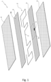
- The invention will be best understood upon perusal of the following description of explanatory and non-limiting embodiments, with reference to the accompanying figure, which shows the radio-frequency identification device in an exploded view.
- In the figure, number 1 indicates, as a whole, a radio-frequency identification (RFID) device according to the invention.
- The device 1 comprises a
transceiver assembly 2, two PET layers 3 arranged in a sandwich-like manner on opposite sides of thetransceiver assembly 2 and two outer rubber layers 4, each arranged on a respectiveouter surface 3a of a PET layer 3. - The two PET layers 3 arranged in a sandwich-like constitute a covering element arranged to completely cover the
transceiver assembly 2. - The
transceiver assembly 2 comprises anRFID chip 5, afirst antenna 6 connected to theRFID chip 5 and a second antenna 7 electromagnetically coupled to thefirst antenna 6. - Two radio-frequency identification (RFID) devices of the type shown in the figure were manufactured. The two devices are different from one another only because one of them was manufactured by depositing an adhesive solution according to the invention on an
outer surface 3a of each PET layer 3. - The adhesive solution was applied on the
surface 3a by means of a brush (deposition operation). - Table I shows the composition, in parts by weight, of the adhesive solution used.
TABLE I Latex styrene-butadiene-vinylpyridine 72.7 Resorcinol 5.0 Formaldehyde 2.3 Methylene diphenyl diisocyanate 20.0 - After having applied the adhesive solution (deposition operation), the two PET layers 3 were subjected to a heating operation. The heating operation involved keeping the two PET layers 3 on which the adhesive solution was applied in an oven at 220°C for an amount of time of 3 minutes.
- Unlike what described above, according to a further embodiment of the invention, the adhesive solution comprises a pre-condensed resin consisting of resorcinol and formaldehyde with isocyanate blocking groups, lignin and a chemical chosen between urea and thiourea. This adhesive solution offers the advantage of not having to use formaldehyde in a free form.
- After having carried out the preliminary step described above, the process goes on with a first step, in which the
transceiver assembly 2 is housed between the two PET layers 3, and, subsequently, with a second step, in which the two PET layers 3 are covered on the outside with two respective layers 4 of non-vulcanized rubber. - Alternatively, the two PET layers 3 can be covered on the outside with two respective layers 4 of partially or totally vulcanized rubber.
- By so doing, a first RFID device was manufactured.
- The second RFID device was manufactured repeating the method described above with the sole exception of not having carried out the preliminary step. In other words, in the manufacturing process of the second RFID device, the first step was carried out using the PET layers 3 without having applied the adhesive solution on them.
- Unlike what described above, according to a preferred embodiment of the invention, the adhesive solution can be applied on both surfaces of the PET layers 3.
- In use, the RFID devices described above are included in a green rubber portion of a tyre.
- Alternatively, the RFID devices described above can be applied on a cured rubber portion of a tyre.
- Once the RFID device has been inserted inside the tyre, the vulcanization step is carried out. By so doing, the rubber layers of the RFID device, during the vulcanization, are cross-linked with the surrounding rubber, ensuring the stability of the position of the device.
- The first and the second RFID devices were subjected to an adhesion test according to ASTM D1876 method. Said test measures the adhesion force between each one of the PET layers 3 and the respective rubber layer 4 arranged so as to cover the
outer surface 3a. - Table II shows the values obtained with the aforesaid test.
TABLE II First RFID device Second RFID device Adhesion force (N/mm) 6.73 0.37 - The values shown in Table II clearly prove that the method of the invention can ensure a strong adhesion between the PET layer 3 and the respective rubber layer 4, thus avoiding a splitting up of the device and the problems caused by it.
- Two other RFID devices (the third and the fourth RFID devices) of the type shown in the figure were manufactured.
- The third and the fourth RFID devices differ from the first and the second RFID devices because they comprise layers 3 made of Nylon and not PET.
- In particular, the two layers 3 of the third and fourth RFID devices are in the form of a textile.
- In addition, the third and the fourth RFID devices differ from each other in the conditions used in the heating operation (b).
- In particular,
- for the third RFID device, the adhesive solution of table I was applied on the
surface 3a of the Nylon layer by means of a brush (deposition operation). - After having applied the adhesive solution (deposition operation), the two Nylon layers 3 were subjected to a heating operation. The heating operation involved keeping the two Nylon layers 3 on which the adhesive solution was applied in an oven at 220°C for an amount of time of 5 minutes.
- for the fourth RFID device, the adhesive solution of table I was applied on the
surface 3a of the Nylon layer by means of a brush (deposition operation). - After having applied the adhesive solution (deposition operation), the two Nylon layers 3 were subjected to a heating operation. The heating operation involved keeping the two Nylon layers 3 on which the adhesive solution was applied in an oven at 155°C for an amount of time of 10 minutes.
- For the first, third and fourth RFID devices the same amount of adhesive solution was applied on the
respective surfaces 3a. - The third and the fourth RFID devices were subjected to an adhesion test according to ASTM D1876 method for measuring the adhesion force between each one of the Nylon layers 3 and the respective rubber layer 4 arranged so as to cover the
outer surface 3a. - Table III shows the values obtained with the aforesaid test.
TABLE III Third RFID device Fourth RFID device Adhesion force (N/mm) 6.9 7.9 - Also the values shown in Table III clearly prove that the method of the invention can ensure a strong adhesion between the Nylon layer 3 and the respective rubber layer 4, thus avoiding a splitting up of the device and the problems caused by it.
- According to the inventors, when the layers of thermoplastic material are in the form of textile, the adhesion force is greater.
- Unlike what described above, instead of two layers arranged in a sandwich-like, the covering element can consist of a layer of thermoplastic material wrapped around the electronic element.
- As stated above, the present invention adapts to any electronic device to be applied to a rubber article, e.g. a tyre.
- Depending on the electronic device, only one rubber layer 4 can be used.
Claims (10)
- Method to manufacture an electronic device (1) to be applied to a rubber article; said device comprising (i) an electronic element (5, 6, 7), (ii) a covering element made of one or more layers (3) of thermoplastic material and arranged to cover said electronic element (5, 6, 7), and (iii) at least a rubber layer (4) arranged to cover at least a part of an outer surface (3a) of said covering element; said method comprising a preliminary step comprising (a) a deposition operation, during which an adhesive solution consisting of a basic water solution comprising a latex of an elastomer rubber and a combination of resorcinol and formaldehyde is applied on said part of one outer surface (3a) of said covering element; and (b) a heating operation, during which said part of the outer surface (3a) of the covering element on which the adhesive solution was applied is kept at a temperature ranging from 120 to 230°C for an amount of time ranging from 2 to 15 min; said method being characterized in that said one or more layers (3) of thermoplastic material are in the form of textile.
- The method according to claim 1, characterized in that said one or more layers of thermoplastic material (3) are made of insulating material.
- The method according to claim 2, characterized in that said insulating material is chosen in the group comprising polyesters, polyamides , polyimides.
- The method according to claim 3, characterized in that said insulating material is comprised in the group consisting of PET, Nylon and polyethylene naphtalate.
- The method according to anyone of the previous claims, characterized in that said basic water solution comprises a pre-condensed resin consisting of resorcinol and formaldehyde with isocyanate blocking groups.
- The method according to claim 5, characterized in that said basic water solution comprises lignin and a chemical chosen between urea and thiourea.
- The method according to anyone of the preceding claims, characterized in that said elastomer rubber latex comprises a latex of styrene-butadiene-vinylpyridine or a latex of a mixture of styrene-butadiene-vinylpyridine and styrene-butadiene.
- The method according to anyone of the preceding claims, characterized in that said rubber article is a tyre.
- The method according to anyone of the preceding claims, characterized in that said electronic element comprises an RFID chip (5), a first antenna (6) connected to the chip (5) and a second antenna (7) electromagnetically coupled to the first antenna (6) or an RFID chip with an electrically coupled antenna.
- An electronic device to be used in rubber article, characterized by being realized by a method according to anyone of the preceding claims.
Applications Claiming Priority (2)
| Application Number | Priority Date | Filing Date | Title |
|---|---|---|---|
| IT202000029513 | 2020-12-02 | ||
| PCT/EP2021/083961 WO2022117725A1 (en) | 2020-12-02 | 2021-12-02 | Method to manufacture an electronic device for a rubber article |
Publications (2)
| Publication Number | Publication Date |
|---|---|
| EP4255742A1 EP4255742A1 (en) | 2023-10-11 |
| EP4255742B1 true EP4255742B1 (en) | 2025-05-21 |
Family
ID=74557208
Family Applications (1)
| Application Number | Title | Priority Date | Filing Date |
|---|---|---|---|
| EP21831243.7A Active EP4255742B1 (en) | 2020-12-02 | 2021-12-02 | Method to manufacture an electronic device for a rubber article |
Country Status (6)
| Country | Link |
|---|---|
| US (1) | US11960953B2 (en) |
| EP (1) | EP4255742B1 (en) |
| JP (1) | JP7610712B2 (en) |
| CN (1) | CN116583847B (en) |
| ES (1) | ES3035999T3 (en) |
| WO (1) | WO2022117725A1 (en) |
Families Citing this family (1)
| Publication number | Priority date | Publication date | Assignee | Title |
|---|---|---|---|---|
| US20220355625A1 (en) * | 2019-08-22 | 2022-11-10 | FineLine Technologies | Chemically treated, rfid equipped mesh tire labels and methods of making and using the same for identification and tracking purposes during and post-tire manufacture |
Family Cites Families (24)
| Publication number | Priority date | Publication date | Assignee | Title |
|---|---|---|---|---|
| FR865460A (en) * | 1939-07-29 | 1941-05-24 | Comp Generale Electricite | Further training in the protection of rubber articles and the like |
| JP4052290B2 (en) | 2003-08-29 | 2008-02-27 | オムロン株式会社 | Wireless IC tag joining method, article with wireless IC tag, and vehicle |
| JP2005216077A (en) * | 2004-01-30 | 2005-08-11 | Bridgestone Corp | Bar code label with built-in rfid, tire and management method therefor |
| JP2005263887A (en) * | 2004-03-17 | 2005-09-29 | Bridgestone Corp | Adhesive composition, method for producing the same, resin material, rubber member, and tire |
| JP4705560B2 (en) | 2006-12-05 | 2011-06-22 | 住友ゴム工業株式会社 | IC tag, pneumatic tire to which it is attached, and method for attaching IC tag |
| JP5217515B2 (en) * | 2008-03-05 | 2013-06-19 | 大日本印刷株式会社 | Method for molding IC tag into rubber material, method for producing rubber sheet with IC tag |
| JP6068005B2 (en) * | 2011-05-31 | 2017-01-25 | 株式会社ブリヂストン | Pneumatic tire and manufacturing method thereof |
| US20140027030A1 (en) * | 2012-07-30 | 2014-01-30 | Andreas Frantzen | Adhesive bonding for a pneumatic tire |
| JP2014132291A (en) * | 2013-01-04 | 2014-07-17 | Sumitomo Chemical Co Ltd | Method for producing optical film, polarizing plate, and image display device |
| CA2831496C (en) * | 2013-10-02 | 2019-05-14 | Weatherford/Lamb, Inc. | Method of operating a downhole tool |
| MX2017004059A (en) | 2014-09-29 | 2017-08-28 | Avery Dennison Corp | Tire tracking rfid label. |
| KR20160050452A (en) * | 2014-10-29 | 2016-05-11 | 아시아나아이디티 주식회사 | Rfid tag attached on surface of tire |
| US9821613B2 (en) * | 2015-07-20 | 2017-11-21 | Bendix Commercial Vehicle Systems Llc | Transmitting device with antenna |
| JP6612141B2 (en) | 2016-01-25 | 2019-11-27 | 株式会社ブリヂストン | RFID tag built-in tire |
| ITUA20163396A1 (en) | 2016-05-12 | 2017-11-12 | Bridgestone Corp | ADHESIVE MIX FOR TIRES FOR TIRES |
| JP6687472B2 (en) * | 2016-06-24 | 2020-04-22 | ブリヂストンスポーツ株式会社 | Golf ball with a built-in IC chip |
| DE102017209552A1 (en) * | 2017-06-07 | 2018-12-13 | Continental Reifen Deutschland Gmbh | A device for reading out data, their uses and a pneumatic vehicle tire comprising the device and a method for producing a pneumatic vehicle tire comprising the device |
| EP3732067B1 (en) * | 2017-12-29 | 2025-04-02 | Pirelli Tyre S.p.A. | Tyre for vehicle wheels comprising an anchoring element of an object to an inner surface of the tyre and process for producing said tyre |
| US12168330B2 (en) * | 2018-11-27 | 2024-12-17 | FineLine Technologies | Systems and methods for maintaining automated quality control during tire manufacture using specialized RFID tags |
| WO2020130197A1 (en) | 2018-12-20 | 2020-06-25 | 엘지전자 주식회사 | Antenna module and mobile terminal |
| US11444485B2 (en) * | 2019-02-05 | 2022-09-13 | Mojo Mobility, Inc. | Inductive charging system with charging electronics physically separated from charging coil |
| IT201900012636A1 (en) * | 2019-07-23 | 2021-01-23 | Bridgestone Europe Nv Sa | METHOD OF MAKING AN ELECTRONIC DEVICE FOR A RUBBER ARTICLE |
| CN111171395A (en) * | 2020-02-17 | 2020-05-19 | 褚乃博 | Composite material made of recycled rubber, forming method and application thereof |
| US20220363092A1 (en) * | 2021-05-12 | 2022-11-17 | David Alan Copeland | Multiplex vehicle wheel assembly types |
-
2021
- 2021-12-02 WO PCT/EP2021/083961 patent/WO2022117725A1/en not_active Ceased
- 2021-12-02 EP EP21831243.7A patent/EP4255742B1/en active Active
- 2021-12-02 US US18/265,003 patent/US11960953B2/en active Active
- 2021-12-02 ES ES21831243T patent/ES3035999T3/en active Active
- 2021-12-02 JP JP2023533980A patent/JP7610712B2/en active Active
- 2021-12-02 CN CN202180081602.2A patent/CN116583847B/en active Active
Also Published As
| Publication number | Publication date |
|---|---|
| CN116583847A (en) | 2023-08-11 |
| EP4255742A1 (en) | 2023-10-11 |
| ES3035999T3 (en) | 2025-09-11 |
| CN116583847B (en) | 2026-03-17 |
| US20240028862A1 (en) | 2024-01-25 |
| JP7610712B2 (en) | 2025-01-08 |
| JP2023552398A (en) | 2023-12-15 |
| WO2022117725A1 (en) | 2022-06-09 |
| US11960953B2 (en) | 2024-04-16 |
Similar Documents
| Publication | Publication Date | Title |
|---|---|---|
| EP4003763B1 (en) | Method to manufacture an electronic device for a rubber article | |
| US12159182B2 (en) | RFID mesh label, tire having RFID mesh label integrally incorporated therein, and methods of making | |
| US12462138B2 (en) | Chemically treated, RFID equipped mesh tire labels and methods of making and using the same for identification and tracking purposes during and post-tire manufacture | |
| EP3877478B1 (en) | Rfid bead label devices capable of withstanding and maintaining rfid operability for identification purposes during and post-vulcanization of rubber articles | |
| EP4255742B1 (en) | Method to manufacture an electronic device for a rubber article | |
| RU2804571C2 (en) | Method for manufacturing electronic device for rubber product | |
| RU2837437C1 (en) | Method of making electronic device for rubber article |
Legal Events
| Date | Code | Title | Description |
|---|---|---|---|
| STAA | Information on the status of an ep patent application or granted ep patent |
Free format text: STATUS: UNKNOWN |
|
| STAA | Information on the status of an ep patent application or granted ep patent |
Free format text: STATUS: THE INTERNATIONAL PUBLICATION HAS BEEN MADE |
|
| PUAI | Public reference made under article 153(3) epc to a published international application that has entered the european phase |
Free format text: ORIGINAL CODE: 0009012 |
|
| STAA | Information on the status of an ep patent application or granted ep patent |
Free format text: STATUS: REQUEST FOR EXAMINATION WAS MADE |
|
| 17P | Request for examination filed |
Effective date: 20230628 |
|
| AK | Designated contracting states |
Kind code of ref document: A1 Designated state(s): AL AT BE BG CH CY CZ DE DK EE ES FI FR GB GR HR HU IE IS IT LI LT LU LV MC MK MT NL NO PL PT RO RS SE SI SK SM TR |
|
| DAV | Request for validation of the european patent (deleted) | ||
| DAX | Request for extension of the european patent (deleted) | ||
| GRAP | Despatch of communication of intention to grant a patent |
Free format text: ORIGINAL CODE: EPIDOSNIGR1 |
|
| STAA | Information on the status of an ep patent application or granted ep patent |
Free format text: STATUS: GRANT OF PATENT IS INTENDED |
|
| INTG | Intention to grant announced |
Effective date: 20241213 |
|
| GRAS | Grant fee paid |
Free format text: ORIGINAL CODE: EPIDOSNIGR3 |
|
| GRAA | (expected) grant |
Free format text: ORIGINAL CODE: 0009210 |
|
| STAA | Information on the status of an ep patent application or granted ep patent |
Free format text: STATUS: THE PATENT HAS BEEN GRANTED |
|
| AK | Designated contracting states |
Kind code of ref document: B1 Designated state(s): AL AT BE BG CH CY CZ DE DK EE ES FI FR GB GR HR HU IE IS IT LI LT LU LV MC MK MT NL NO PL PT RO RS SE SI SK SM TR |
|
| REG | Reference to a national code |
Ref country code: GB Ref legal event code: FG4D |
|
| REG | Reference to a national code |
Ref country code: CH Ref legal event code: EP |
|
| REG | Reference to a national code |
Ref country code: DE Ref legal event code: R096 Ref document number: 602021031237 Country of ref document: DE |
|
| P01 | Opt-out of the competence of the unified patent court (upc) registered |
Free format text: CASE NUMBER: APP_22596/2025 Effective date: 20250513 |
|
| REG | Reference to a national code |
Ref country code: IE Ref legal event code: FG4D |
|
| REG | Reference to a national code |
Ref country code: ES Ref legal event code: FG2A Ref document number: 3035999 Country of ref document: ES Kind code of ref document: T3 Effective date: 20250911 |
|
| REG | Reference to a national code |
Ref country code: NL Ref legal event code: MP Effective date: 20250521 |
|
| PG25 | Lapsed in a contracting state [announced via postgrant information from national office to epo] |
Ref country code: PT Free format text: LAPSE BECAUSE OF FAILURE TO SUBMIT A TRANSLATION OF THE DESCRIPTION OR TO PAY THE FEE WITHIN THE PRESCRIBED TIME-LIMIT Effective date: 20250922 Ref country code: FI Free format text: LAPSE BECAUSE OF FAILURE TO SUBMIT A TRANSLATION OF THE DESCRIPTION OR TO PAY THE FEE WITHIN THE PRESCRIBED TIME-LIMIT Effective date: 20250521 |
|
| REG | Reference to a national code |
Ref country code: LT Ref legal event code: MG9D |
|
| PG25 | Lapsed in a contracting state [announced via postgrant information from national office to epo] |
Ref country code: NO Free format text: LAPSE BECAUSE OF FAILURE TO SUBMIT A TRANSLATION OF THE DESCRIPTION OR TO PAY THE FEE WITHIN THE PRESCRIBED TIME-LIMIT Effective date: 20250821 Ref country code: GR Free format text: LAPSE BECAUSE OF FAILURE TO SUBMIT A TRANSLATION OF THE DESCRIPTION OR TO PAY THE FEE WITHIN THE PRESCRIBED TIME-LIMIT Effective date: 20250822 |
|
| PG25 | Lapsed in a contracting state [announced via postgrant information from national office to epo] |
Ref country code: PL Free format text: LAPSE BECAUSE OF FAILURE TO SUBMIT A TRANSLATION OF THE DESCRIPTION OR TO PAY THE FEE WITHIN THE PRESCRIBED TIME-LIMIT Effective date: 20250521 Ref country code: NL Free format text: LAPSE BECAUSE OF FAILURE TO SUBMIT A TRANSLATION OF THE DESCRIPTION OR TO PAY THE FEE WITHIN THE PRESCRIBED TIME-LIMIT Effective date: 20250521 |
|
| PG25 | Lapsed in a contracting state [announced via postgrant information from national office to epo] |
Ref country code: BG Free format text: LAPSE BECAUSE OF FAILURE TO SUBMIT A TRANSLATION OF THE DESCRIPTION OR TO PAY THE FEE WITHIN THE PRESCRIBED TIME-LIMIT Effective date: 20250521 |
|
| PG25 | Lapsed in a contracting state [announced via postgrant information from national office to epo] |
Ref country code: HR Free format text: LAPSE BECAUSE OF FAILURE TO SUBMIT A TRANSLATION OF THE DESCRIPTION OR TO PAY THE FEE WITHIN THE PRESCRIBED TIME-LIMIT Effective date: 20250521 |
|
| PG25 | Lapsed in a contracting state [announced via postgrant information from national office to epo] |
Ref country code: RS Free format text: LAPSE BECAUSE OF FAILURE TO SUBMIT A TRANSLATION OF THE DESCRIPTION OR TO PAY THE FEE WITHIN THE PRESCRIBED TIME-LIMIT Effective date: 20250821 |
|
| PG25 | Lapsed in a contracting state [announced via postgrant information from national office to epo] |
Ref country code: IS Free format text: LAPSE BECAUSE OF FAILURE TO SUBMIT A TRANSLATION OF THE DESCRIPTION OR TO PAY THE FEE WITHIN THE PRESCRIBED TIME-LIMIT Effective date: 20250921 |
|
| PG25 | Lapsed in a contracting state [announced via postgrant information from national office to epo] |
Ref country code: LV Free format text: LAPSE BECAUSE OF FAILURE TO SUBMIT A TRANSLATION OF THE DESCRIPTION OR TO PAY THE FEE WITHIN THE PRESCRIBED TIME-LIMIT Effective date: 20250521 |
|
| REG | Reference to a national code |
Ref country code: AT Ref legal event code: MK05 Ref document number: 1796476 Country of ref document: AT Kind code of ref document: T Effective date: 20250521 |
|
| PGFP | Annual fee paid to national office [announced via postgrant information from national office to epo] |
Ref country code: DE Payment date: 20251126 Year of fee payment: 5 |
|
| PG25 | Lapsed in a contracting state [announced via postgrant information from national office to epo] |
Ref country code: DK Free format text: LAPSE BECAUSE OF FAILURE TO SUBMIT A TRANSLATION OF THE DESCRIPTION OR TO PAY THE FEE WITHIN THE PRESCRIBED TIME-LIMIT Effective date: 20250521 Ref country code: SM Free format text: LAPSE BECAUSE OF FAILURE TO SUBMIT A TRANSLATION OF THE DESCRIPTION OR TO PAY THE FEE WITHIN THE PRESCRIBED TIME-LIMIT Effective date: 20250521 Ref country code: AT Free format text: LAPSE BECAUSE OF FAILURE TO SUBMIT A TRANSLATION OF THE DESCRIPTION OR TO PAY THE FEE WITHIN THE PRESCRIBED TIME-LIMIT Effective date: 20250521 |
|
| PGFP | Annual fee paid to national office [announced via postgrant information from national office to epo] |
Ref country code: FR Payment date: 20251119 Year of fee payment: 5 |
|
| PG25 | Lapsed in a contracting state [announced via postgrant information from national office to epo] |
Ref country code: CZ Free format text: LAPSE BECAUSE OF FAILURE TO SUBMIT A TRANSLATION OF THE DESCRIPTION OR TO PAY THE FEE WITHIN THE PRESCRIBED TIME-LIMIT Effective date: 20250521 |
|
| PG25 | Lapsed in a contracting state [announced via postgrant information from national office to epo] |
Ref country code: EE Free format text: LAPSE BECAUSE OF FAILURE TO SUBMIT A TRANSLATION OF THE DESCRIPTION OR TO PAY THE FEE WITHIN THE PRESCRIBED TIME-LIMIT Effective date: 20250521 |
|
| PG25 | Lapsed in a contracting state [announced via postgrant information from national office to epo] |
Ref country code: SK Free format text: LAPSE BECAUSE OF FAILURE TO SUBMIT A TRANSLATION OF THE DESCRIPTION OR TO PAY THE FEE WITHIN THE PRESCRIBED TIME-LIMIT Effective date: 20250521 |
|
| PG25 | Lapsed in a contracting state [announced via postgrant information from national office to epo] |
Ref country code: IT Free format text: LAPSE BECAUSE OF FAILURE TO SUBMIT A TRANSLATION OF THE DESCRIPTION OR TO PAY THE FEE WITHIN THE PRESCRIBED TIME-LIMIT Effective date: 20250521 |
|
| REG | Reference to a national code |
Ref country code: DE Ref legal event code: R097 Ref document number: 602021031237 Country of ref document: DE |
|
| PG25 | Lapsed in a contracting state [announced via postgrant information from national office to epo] |
Ref country code: RO Free format text: LAPSE BECAUSE OF FAILURE TO SUBMIT A TRANSLATION OF THE DESCRIPTION OR TO PAY THE FEE WITHIN THE PRESCRIBED TIME-LIMIT Effective date: 20250521 |
|
| PLBE | No opposition filed within time limit |
Free format text: ORIGINAL CODE: 0009261 |
|
| STAA | Information on the status of an ep patent application or granted ep patent |
Free format text: STATUS: NO OPPOSITION FILED WITHIN TIME LIMIT |
|
| REG | Reference to a national code |
Ref country code: CH Ref legal event code: L10 Free format text: ST27 STATUS EVENT CODE: U-0-0-L10-L00 (AS PROVIDED BY THE NATIONAL OFFICE) Effective date: 20260402 |
|
| PGFP | Annual fee paid to national office [announced via postgrant information from national office to epo] |
Ref country code: ES Payment date: 20260102 Year of fee payment: 5 |
|
| 26N | No opposition filed |
Effective date: 20260224 |