EP4255090A1 - Data transmission method, terminal devices, and network device - Google Patents
Data transmission method, terminal devices, and network device Download PDFInfo
- Publication number
- EP4255090A1 EP4255090A1 EP21921815.3A EP21921815A EP4255090A1 EP 4255090 A1 EP4255090 A1 EP 4255090A1 EP 21921815 A EP21921815 A EP 21921815A EP 4255090 A1 EP4255090 A1 EP 4255090A1
- Authority
- EP
- European Patent Office
- Prior art keywords
- information
- type
- terminal device
- session
- relay
- Prior art date
- Legal status (The legal status is an assumption and is not a legal conclusion. Google has not performed a legal analysis and makes no representation as to the accuracy of the status listed.)
- Granted
Links
Images


Classifications
-
- H—ELECTRICITY
- H04—ELECTRIC COMMUNICATION TECHNIQUE
- H04W—WIRELESS COMMUNICATION NETWORKS
- H04W40/00—Communication routing or communication path finding
- H04W40/02—Communication route or path selection, e.g. power-based or shortest path routing
- H04W40/22—Communication route or path selection, e.g. power-based or shortest path routing using selective relaying for reaching a BTS [Base Transceiver Station] or an access point
-
- H—ELECTRICITY
- H04—ELECTRIC COMMUNICATION TECHNIQUE
- H04W—WIRELESS COMMUNICATION NETWORKS
- H04W76/00—Connection management
- H04W76/10—Connection setup
- H04W76/12—Setup of transport tunnels
-
- H—ELECTRICITY
- H04—ELECTRIC COMMUNICATION TECHNIQUE
- H04W—WIRELESS COMMUNICATION NETWORKS
- H04W76/00—Connection management
- H04W76/10—Connection setup
- H04W76/14—Direct-mode setup
-
- H—ELECTRICITY
- H04—ELECTRIC COMMUNICATION TECHNIQUE
- H04W—WIRELESS COMMUNICATION NETWORKS
- H04W92/00—Interfaces specially adapted for wireless communication networks
- H04W92/16—Interfaces between hierarchically similar devices
- H04W92/18—Interfaces between hierarchically similar devices between terminal devices
-
- H—ELECTRICITY
- H04—ELECTRIC COMMUNICATION TECHNIQUE
- H04L—TRANSMISSION OF DIGITAL INFORMATION, e.g. TELEGRAPHIC COMMUNICATION
- H04L45/00—Routing or path finding of packets in data switching networks
- H04L45/66—Layer 2 routing, e.g. in Ethernet based MAN's
-
- H—ELECTRICITY
- H04—ELECTRIC COMMUNICATION TECHNIQUE
- H04W—WIRELESS COMMUNICATION NETWORKS
- H04W88/00—Devices specially adapted for wireless communication networks, e.g. terminals, base stations or access point devices
- H04W88/02—Terminal devices
- H04W88/04—Terminal devices adapted for relaying to or from another terminal or user
Definitions
- This disclosure relates to the field of communication, and more particularly to a method for data transmission, a terminal device, and a network device.
- a user equipment (UE) having proximity-based service (ProSe) capability can communicate directly with another UE having ProSe capability over a short-range communication connection interface. If a UE can be connected to an external data network over a communication network and also has ProSe capability, the UE can act as a relay UE, and another remote UE having ProSe capability can establish a direct connection with the relay UE over a short-range communication interface and communicate with an external network over a session established between the relay UE and the communication network.
- ProSe proximity-based service
- a session established between the relay UE and the core network has various types, where different types of sessions can be used for transmitting data of corresponding types, and relay data transmitted between the remote UE and the relay UE may also have various types, and as a result, the type of the session between the relay UE and the core network may be incompatible with the type of relay data sent by the remote UE. For example, if the relay data transmitted between the remote UE and the relay UE cannot be transmitted over the type of the session established between the relay UE and the core network, the relay UE will be unable to transfer correctly data received from the remote UE, thus resulting in failure in data transmission.
- Implementations of the disclosure provide a method for data transmission, a terminal device, and a network device, which can ensure that relay data is correctly transmitted between a relay and a network.
- Implementations of the disclosure provide a method for data transmission.
- the method includes the following.
- a first terminal device receives first information and relay-data type information corresponding to the first information from a network device, where the relay-data type information is indicative a type of relay data.
- the first terminal device sends relay data of the type to a second terminal device.
- Implementations of the disclosure further provide a method for session establishment.
- the method includes the following.
- a second terminal device receives first information and first-session type information corresponding to the first information from a network device, where the first-session type information is indicative of a type of a first session.
- the second terminal device establishes the first session of the type.
- Implementations of the disclosure further provide a method for transmission type configuration.
- the method includes the following.
- a network device sends first information and relay-data type information corresponding to the first information to a first terminal device, and sends the first information and first-session type information corresponding to the first information to a second terminal device, where the relay-data type information is indicative of a first type of relay data, and the first-session type information is indicative of a second type of a first session.
- Relay data of the first type can be transmitted over the first session of the second type.
- Implementations of the disclosure further provide a first terminal device.
- the first terminal device includes a first receiving module and a first transmitting module.
- the first receiving module is configured to receive first information and relay-data type information corresponding to the first information from a network device, where the relay-data type information indicates a type of relay data.
- the first transmitting module is configured to send relay data of the type to a second terminal device.
- Implementations of the disclosure also provide a second terminal device.
- the second terminal device includes a second receiving module and a session establishing module.
- the second receiving module is configured to receive first information and first-session type information corresponding to the first information from a network device, where the first-session type information is indicative of a type of a first session.
- the session establishing module is configured to establish the first session of the type.
- Implementations of the disclosure further provide a network device.
- the network device includes a second transmitting module.
- the second transmitting module is configured to send first information and relay-data type information corresponding to the first information to a first terminal device, and send the first information and first-session type information corresponding to the first information to a second terminal device, where the relay-data type information is indicative of a first type of relay data, and the first-session type information is indicative of a second type of a first session.
- Relay data of the first type can be transmitted over the first session of the second type.
- Implementations of the disclosure further provide a terminal device.
- the terminal device includes a processor, a memory, and a transceiver.
- the memory is configured to store computer programs.
- the processor is configured to invoke and execute the computer programs stored in the memory and control the transceiver to perform any one of the methods described above.
- Implementations of the disclosure further provide a network device.
- the network device includes a processor, a memory, and a transceiver.
- the memory is configured to store computer programs.
- the processor is configured to invoke and execute the computer programs stored in the memory and control the transceiver to perform any one of the methods described above.
- Implementations of the disclosure further provide a chip.
- the chip includes a processor.
- the processor is configured to invoke and execute computer programs stored in a memory, to cause a device equipped with the chip to perform any one of the methods described above.
- Implementations of the disclosure further provide a computer-readable storage medium.
- the computer-readable storage medium is configured to store computer programs which are operable with a computer to perform any one of the methods described above.
- Implementations of the disclosure further provide a computer program product.
- the computer program product includes computer program instructions which are operable with a computer to perform any one of the methods described above.
- Implementations of the disclosure further provide a computer program.
- the computer program is operable with a computer to perform any one of the methods described above.
- the first terminal device sends relay data of the type according to the type of relay data configured by the network device, which can ensure that the relay data is correctly transmitted between a relay and a network.
- GSM global system of mobile communication
- CDMA code division multiple access
- WCDMA wideband code division multiple access
- GPRS general packet radio service
- LTE long term evolution
- LTE-A advanced LTE
- NR new radio
- UMTS universal mobile telecommunication system
- WLAN wireless local area network
- WiFi wireless fidelity
- 5G 5 th generation
- a conventional communication system generally supports a limited quantity of connections and therefore is easy to implement.
- a mobile communication system will not only support conventional communication but also support, for example, device to device (D2D) communication, machine to machine (M2M) communication, machine type communication (MTC), and vehicle to vehicle (V2V) communication, etc. Implementations of the disclosure can also be applied to these communication systems.
- D2D device to device
- M2M machine to machine
- MTC machine type communication
- V2V vehicle to vehicle
- the communication system in implementations of the disclosure may be applied to a carrier aggregation (CA) scenario, a dual connectivity (DC) scenario, or a standalone (SA) network deployment scenario.
- CA carrier aggregation
- DC dual connectivity
- SA standalone
- the communication system in implementations of the disclosure is applicable to a licensed spectrum, or is applicable to an unlicensed spectrum.
- the terminal device may also be referred to as a user equipment (UE), an access terminal, a subscriber unit, a subscriber station, a mobile station, a remote station, a remote terminal, a mobile device, a user terminal, a terminal, a wireless communication device, a user agent, or a user device, etc.
- UE user equipment
- the terminal device may be a station (ST) in a WLAN, a cellular radio telephone, a cordless telephone, a session initiation protocol (SIP) telephone, a wireless local loop (WLL) station, a personal digital assistant (PDA), a handheld device or a computing device with wireless communication functions, other processing devices coupled with a wireless modem, an in-vehicle device, a wearable device, and a terminal device in a next-generation communication system, for example, a terminal device in an NR network, or a terminal device in a future evolved public land mobile network (PLMN), etc.
- ST station
- WLAN wireless local loop
- PDA personal digital assistant
- the terminal device may also be a wearable device.
- the wearable device may also be called a wearable smart device, which is a generic term of wearable devices obtained through intelligentization design and development on daily wearing products with wearable technology, for example, glasses, gloves, watches, clothes, accessories, and shoes.
- the wearable device is a portable device that can be directly worn or integrated into clothes or accessories of a user.
- the wearable device can also realize various functions through software support, data interaction, and cloud interaction.
- a wearable smart device in a broad sense includes, for example, a smart watch or smart glasses with complete functions and large sizes and capable of realizing independently all or part of functions of a smart phone, and for example, various types of smart bands and smart jewelries for physical monitoring, of which each is dedicated to application functions of a certain type and required to be used together with other devices such as a smart phone.
- the network device may be a device for communicating with a mobile device, and the network device may be an access point (AP) in a WLAN, a base transceiver station (BTS) in GSM or CDMA, may also be a Node B (NB) in WCDMA, and may also be an evolutional Node B (eNB or eNodeB) in LTE, or a relay station or an AP, or an in-vehicle device, a wearable device, a gNB in an NR network, or network device in a future evolved PLMN, etc.
- AP access point
- BTS base transceiver station
- NB Node B
- eNB evolutional Node B
- eNodeB evolutional Node B
- the network device provides services for a cell
- the terminal device communicates with the network device on a transmission resource (for example, a frequency-domain resource or a spectrum resource) for the cell.
- the cell may be a cell corresponding to the network device (for example, a base station).
- the cell may belong to a macro base station, or may belong to a base station corresponding to a small cell.
- the small cell may include: a metro cell, a micro cell, a pico cell, a femto cell, and the like. These small cells are characterized by small coverage and low transmission power and are adapted to provide data transmission service with high-rate.
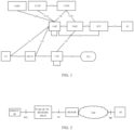
- FIG. 1 exemplarily illustrates an architectural diagram of a 5 th generation (5G) network system 100.
- a UE establishes an access stratum (AS) connection with an access network (AN) over a UE-universal mobile telecommunication system (UMTS) terrestrial radio access network (UE-UTRAN, Uu) interface, and communicates an AS message and performs wireless data transmission with the AN.
- the UE establishes a non-access stratum (NAS) connection with an access and mobility management function (AMF) over an N1 interface and communicates an NAS message with the AMF.
- the AMF is also responsible for forwarding a session management-related message between the UE and a session management function (SMF).
- SMF session management function
- a policy control function is responsible for providing policies related to mobility management, session management, and charging for the UE.
- a user plane function performs data transmission with an external data network (DN) over an N6 interface, and performs data transmission with the AN over an N3 interface. After accessing a 5G network over the Uu interface, the UE establishes a protocol data unit (PDU) session under control of the SMF for data transmission.
- PDU protocol data unit
- system and “network” herein are usually used interchangeably throughout this disclosure.
- the term “and/or” herein only describes an association relationship between associated objects, which means that there can be three relationships. For example, A and/or B can mean A alone, both A and B exist, and B alone.
- the character “j” herein generally indicates that the associated objects are in an "or" relationship.
- indication may be a direct indication, may be an indirect indication, or may mean that there is an association relationship.
- a indicates B may mean that A directly indicates B, for instance, B can be obtained according to A; may mean that A indirectly indicates B, for instance, A indicates C, and B can be obtained according to C; or may mean that that there is an association relationship between A and B.
- correspondence may mean that there is a direct or indirect correspondence between the two, may mean that there is an association between the two, or may mean a relationship of indicating and indicated or configuring and configured, etc.
- FIG. 2 is a block diagram of a system 200 for relay transmission using a proximity-based service (ProSe) function in a 5G network.
- ProSe proximity-based service
- a UE having ProSe capability can communicate directly with another UE having ProSe capability over a ProSe communication (interface) 5 (PC5 interface).
- PC5 interface ProSe communication
- the UE can act as a relay UE, and another remote UE having ProSe capability can establish a direct connection with the relay UE over a PC5 interface and communicate with an external network over a PDU session established between the relay UE and the 5G network.
- a PDU session established between the relay UE and the core network may be of an internet protocol (IP) type, an Ethernet type, or an unstructured type, which are respectively used for transmitting data with an IP packet header, data with an Ethernet packet header, and data with an unstructured packet header.
- IP internet protocol
- Data transmitted between the remote UE and the relay UE may also be of an IP type, an Ethernet type, or an unstructured type. If the type of data to-be-relayed (hereinafter, "relay data" for short) sent from the remote UE to the relay UE is inconsistent with the type of the PDU session established between the relay UE and the core network, the relay UE may be unable to transfer correctly data received from the remote UE.
- the PDU session established between the relay UE and the core network is of the Ethernet type, but relay data received by the relay UE from the remote UE is of the IP type or the unstructured type; or the PDU session established between the relay UE and the core network is of the unstructured type, but the relay data received by the relay UE from the remote UE is of the IP type or the Ethernet type.
- the relay UE cannot perform relay transmission of data.
- the disclosure provides a method for data transmission.
- the method provided in the disclosure can not only be applied to a 5G network but also be applied to other communication networks.
- FIG. 3 is a schematic flowchart of a method 300 for data transmission according to implementations of the disclosure.
- the method optionally can be applied to the system illustrated in FIG. 1 or FIG. 2 , but is not limited thereto.
- the method includes at least some of the following.
- a first terminal device receives first information and relay-data type information corresponding to the first information from a network device, where the relay-data type information is indicative a type of relay data.
- the first terminal device sends relay data of the type to a second terminal device.
- the first terminal device includes a terminal device acting as a remote UE
- the second terminal device includes a terminal device acting as a relay UE.
- the type of relay data includes an IP type, an Ethernet type, or an unstructured type.
- the first information includes at least one of: a relay service code (RSC), application information, domain name information, or connection capability information requested by an application.
- RSC relay service code
- the application information may be an application identity (ID).
- connection capability information requested by an application may be an instant-messaging connection, an Internet connection, or the like.
- the first terminal device receives the first information and the relay-data type information corresponding to the first information from the network device in step S310 as follows.
- the first terminal device receives a short-range communication configuration from the network device, where the short-range communication configuration includes the first information and the relay-data type information corresponding to the first information.
- the method may further include the following.
- the first terminal device establishes a short-range communication connection with the second terminal device, where the short-range communication connection corresponds to the first information.
- the short-range communication connection may be a PC5 connection.
- the first terminal device can send the relay data of the type corresponding to the first information over the short-range communication connection between the first terminal device and the second terminal device corresponding to the first information.
- the network device includes a PCF.
- the method is applied to a 5G network
- the network device is a PCF
- the first terminal device is a remote UE
- the second terminal device is a relay UE.
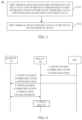
- FIG. 4 is a flowchart illustrating implementation of embodiment I of the disclosure, which includes the following.
- a PCF sends a short-range communication configuration to a terminal acting as a relay UE.
- the short-range communication configuration includes the first information and a PDU session type (hereinafter, "second type" for short) corresponding to the first information.
- the PDU session type includes an IP type, an Ethernet type, or an unstructured type.
- the first information includes one or more of: an RSC, application information (e. g. application ID), domain name information, or connection capability information requested by an application (e. g. instant-messaging connection, Internet connection).
- the PCF sends a short-range communication configuration to a terminal acting as a remote UE.
- the short-range communication configuration includes the first information and a relay-data type (hereinafter, "first type" for short) corresponding to the first information.
- the relay-data type includes an IP type, an Ethernet type, or an unstructured type.
- the first information includes one or more of: an RSC, application information (e. g. application ID), domain name information, or connection capability information requested by an application (e. g. instant-messaging connection, Internet connection).
- the PCF When configuring the relay-data type and the PDU session type, the PCF needs to ensure that relay data of the first type can be transmitted over the PDU session of the second type.
- the relay-data type corresponding to the first information configured for the remote UE is also the Ethernet type.
- the relay-data type corresponding to the first information configured for the remote UE is also the unstructured type.
- the relay-data type corresponding to the first information configured for the remote UE may be the IP type, the Ethernet type, or the unstructured type.
- a PC5 connection corresponding to the first information is established between the remote UE and the relay UE.
- the first information is an RSC
- a procedure for PC5 connection establishment may include the following.
- the relay UE broadcasts multiple RSCs supported by the relay UE.
- the remote UE selects one RSC from the multiple RSCs supported by the relay UE, and sends a short-range connection establishment request to the relay UE to request to establish a PC5 connection corresponding to the RSC.
- the relay UE replies a short-range connection establishment response to the remote UE, and establishes a PC5 connection between the relay UE and the remote UE corresponding to the RSC.
- a short-range communication connection between the remote UE and the relay UE may also be established in other manners, and the short-range communication connection may be a PC5 connection or other forms of communication connection.
- the remote UE determines the relay-data type according to the short-range communication configuration obtained from the PCF, and sends relay data of the type to the relay UE over the PC5 connection between the relay UE and the remote UE.
- the relay UE determines a PDU session type between the relay UE and a core network corresponding to the first information according to the short-range communication configuration obtained from the PCF, establishes a PDU session of the type, and relays, over the PDU session, data received from the remote UE. Since relay data of the first type can be transmitted over the PDU session of the second type configured by the PCF, the data received from the remote UE by the relay UE can be transmitted correctly.
- FIG. 5 is a flowchart illustrating implementation of Embodiment II of the disclosure.
- a PCF sends a UE route selection policy to a terminal acting as a relay UE, where the UE route selection policy includes the first information and a PDU session type corresponding to the first information.
- the above examples are merely illustrative, and the method provided in the disclosure can be applied not only to a 5G network, and the session established between the relay UE and the core network is not limited to a PDU session.
- FIG. 6 is a schematic flowchart of a method 600 for session establishment according to implementations of the disclosure.
- the method optionally can be applied to the system illustrated in FIG. 1 or FIG. 2 , but is not limited thereto.
- the method includes at least some the following.
- a second terminal device receives first information and first-session type information corresponding to the first information from a network device, where the first-session type information is indicative of a type of a first session.
- the second terminal device establishes the first session of the type.
- the first session includes a PDU session.
- the type of the first session includes an IP type, an Ethernet type, or an unstructured type.
- the first information includes at least one of: an RSC, application information, domain name information, or connection capability information requested by an application.
- the second terminal device receives the first information and the first-session type information corresponding to the first information from the network device as follows.
- the second terminal device receives a short-range communication configuration from the network device, where the short-range communication configuration includes the first information and the first-session type information corresponding to the first information.
- the second terminal device receives the first information and the first-session type information corresponding to the first information from the network device as follows.
- the second terminal device receives a UE route selection policy from the network device, where the UE route selection policy includes the first information and the first-session type information corresponding to the first information.
- the second terminal device establishes the first session of the type as follows.
- the second terminal device establishes the first session of the type corresponding to the first information.
- the method further includes the following.
- the second terminal device receives relay data from a first terminal device.
- the second terminal device sends the relay data over the first session of the type.
- the first terminal device includes a terminal device acting as a remote UE.
- the second terminal device includes a terminal device acting as a relay UE.
- the network device includes a PCF.
- FIG. 7 is a schematic flowchart of a method 700 for transmission type configuration according to implementations of the disclosure.
- the method optionally can be applied to the system illustrated in FIG. 1 or FIG. 2 , but is not limited thereto.
- the method includes at least some of the following.
- a network device sends first information and relay-data type information corresponding to the first information to a first terminal device, and sends the first information and first-session type information corresponding to the first information to a second terminal device, where the relay-data type information is indicative of a first type of relay data, and the first-session type information is indicative of a second type of a first session.
- Relay data of the first type can be transmitted over the first session of the second type.
- the first session includes a PDU session.
- the first type of relay data includes an IP type, an Ethernet type, or an unstructured type
- the second type of the first session includes an IP type, an Ethernet type, or an unstructured type
- the relay-data type information indicates that the first type of relay data corresponding to the first information is the Ethernet type
- the first-session type information indicates that the second type of the first session corresponding to the first information is the Ethernet type
- the relay-data type information indicates that the first type of relay data corresponding to the first information is the unstructured type
- the first-session type information indicates that the second type of the first session corresponding to the first information is the unstructured type.
- the relay-data type information indicates that the first type of relay data corresponding to the first information is the IP type, the Ethernet type, or the unstructured type
- the first-session type information indicates that the second type of the first session corresponding to the first information is the IP type.
- the first information includes at least one of: an RSC, application information, domain name information, or connection capability information requested by an application.
- the network device sends the first information and the relay-data type information corresponding to the first information to the first terminal device as follows.
- the network device sends a short-range communication configuration to the first terminal device, where the short-range communication configuration includes the first information and the relay-data type information corresponding to the first information.
- the network device sends the first information and the first-session type information corresponding to the first information to the second terminal device as follows.
- the network device sends a short-range communication configuration to the second terminal device, where the short-range communication configuration includes the first information and the first-session type information corresponding to the first information.
- the network device sends the first information and the first-session type information corresponding to the first information to the second terminal device as follows.
- the network device sends a UE route selection policy to the second terminal device, where the UE route selection policy includes the first information and the first-session type information corresponding to the first information.
- the network device includes a PCF.
- the first terminal device includes a terminal device acting as a remote UE.
- the second terminal device includes a terminal device acting as a relay UE.
- FIG. 8 is a schematic structural diagram of a first terminal device 800 according to implementations of the disclosure.
- the first terminal device 800 includes a first receiving module 810 and a first transmitting module 820.
- the first receiving module 810 is configured to receive first information and relay-data type information corresponding to the first information from a network device, where the relay-data type information indicates a type of relay data.
- the first transmitting module 820 is configured to send relay data of the type to a second terminal device.
- the type of relay data includes an IP type, an Ethernet type, or an unstructured type.
- the first information includes at least one of: an RSC, application information, domain name information, or connection capability information requested by an application.
- the first receiving module 810 is configured to receive a short-range communication configuration from the network device, where the short-range communication configuration includes the first information and the relay-data type information corresponding to the first information.
- the first terminal device further includes a communication-connection establishing module.
- the communication-connection establishing module is configured to establish a short-range communication connection with the second terminal device, where the short-range communication connection corresponds to the first information.
- the first terminal device includes a terminal device acting as a remote UE
- the second terminal device includes a terminal device acting as a relay UE.
- the network device includes a PCF.
- FIG. 9 is a schematic structural diagram of a second terminal device 900 according to implementations of the disclosure.
- the second terminal device 900 includes a second receiving module 910 and a session establishing module 920.
- the second receiving module 910 is configured to receive first information and first-session type information corresponding to the first information from a network device, where the first-session type information is indicative of a type of a first session.
- the session establishing module 920 is configured to establish the first session of the type.
- the first session includes a PDU session.
- the type of the first session includes an IP type, an Ethernet type, or an unstructured type.
- the first information includes at least one of: an RSC, application information, domain name information, or connection capability information requested by an application.
- the second receiving module 910 is configured to receive a short-range communication configuration from the network device, where the short-range communication configuration includes the first information and the first-session type information corresponding to the first information.
- the second receiving module 910 is configured to receive a UE route selection policy from the network device, where the UE route selection policy includes the first information and the first-session type information corresponding to the first information.
- the session establishing module 920 is configured to establish the first session of the type corresponding to the first information.
- the second terminal device further includes a relay module.
- the relay module is configured to receive relay data from a first terminal device, and send the relay data over the first session of the type.
- the first terminal device includes a terminal device acting as a remote UE.
- the second terminal device includes a terminal device acting as a relay UE.
- the network device includes a PCF.
- FIG. 10 is a schematic structural diagram of a network device 1000 according to implementations of the disclosure.
- the network device 1000 includes a second transmitting module 1010.
- the second transmitting module 1010 is configured to send first information and relay-data type information corresponding to the first information to a first terminal device, and send the first information and first-session type information corresponding to the first information to a second terminal device, where the relay-data type information is indicative of a first type of relay data, and the first-session type information is indicative of a second type of a first session.
- Relay data of the first type can be transmitted over the first session of the second type.
- the first session includes a PDU session.
- the first type of relay data includes an IP type, an Ethernet type, or an unstructured type
- the second type of the first session includes an IP type, an Ethernet type, or an unstructured type
- the relay-data type information indicates that the first type of relay data corresponding to the first information is the Ethernet type
- the first-session type information indicates that the second type of the first session corresponding to the first information is the Ethernet type
- the relay-data type information indicates that the first type of relay data corresponding to the first information is the unstructured type
- the first-session type information indicates that the second type of the first session corresponding to the first information is the unstructured type.
- the relay-data type information indicates that the first type of relay data corresponding to the first information is the IP type, the Ethernet type, or the unstructured type
- the first-session type information indicates that the second type of the first session corresponding to the first information is the IP type.
- the first information includes at least one of: an RSC, application information, domain name information, or connection capability information requested by an application.
- the second transmitting module 1010 is configured to send a short-range communication configuration to the first terminal device, where the short-range communication configuration includes the first information and the relay-data type information corresponding to the first information.
- the second transmitting module 1010 is configured to send a short-range communication configuration to the second terminal device, where the short-range communication configuration includes the first information and the first-session type information corresponding to the first information.
- the second transmitting module 1010 is configured to send a UE route selection policy to the second terminal device, where the UE route selection policy includes the first information and the first-session type information corresponding to the first information.
- the network device includes a PCF.
- the first terminal device includes a terminal device acting as a remote UE
- the second terminal device includes a terminal device acting as a relay UE.
- functions of various modules (sub-modules, units, or components, etc.) in the first terminal device 800, the second terminal device 900, and the network device 1000 in implementations of the disclosure may be implemented by different modules (sub-modules, units, or components, etc.), or may be implemented by the same module (sub-module, unit, or component, etc.).
- the first transmitting module and the second transmitting module may be different modules or may be the same module, all of which can implement the corresponding functions thereof in implementations of the disclosure.
- the transmitting module and the receiving module in implementations of the disclosure may be implemented by a transceiver of a device, and some or all of the other modules may be implemented by a processor of the device.
- FIG. 11 is a schematic structural diagram of a communication device 1100 according to implementations of the disclosure.
- the communication device 1100 illustrated in FIG. 11 includes a processor 1110.
- the processor 1110 can invoke and execute computer programs stored in a memory, to perform the method in implementations of the disclosure.
- the communication device 1100 may further include the memory 1120.
- the processor 1110 can invoke and execute the computer programs stored in the memory 1120, to perform the method in implementations of the disclosure.
- the memory 1120 may be a separate device independent of the processor 1110, or may be integrated into the processor 1110.
- the communication device 1100 can further include a transceiver 1130.
- the processor 1110 can control the transceiver 1130 to communicate with other devices, specifically, to transmit information or data to other devices or to receive information or data transmitted by other devices.
- the transceiver 1130 may include a transmitter and a receiver.
- the transceiver 1130 may further include an antenna, where one or more antennas can be provided.
- the communication device 1100 may be operable as the first terminal device or the second terminal device in implementations of the disclosure, and the communication device 1100 can implement the operations performed by the first terminal device or the second terminal device in various methods in implementations of the disclosure, which will not be repeated herein for the sake of brevity.
- the communication device 1100 may be operable as the network device in implementations of the disclosure, and the communication device 1100 can implement the operations performed by the network device in various methods in implementations of the disclosure, which will not be repeated herein for the sake of brevity.
- FIG. 12 is a schematic structural diagram of a chip 1200 according to implementations of the disclosure.
- the chip 1200 illustrated in FIG. 12 includes a processor 1210.
- the processor 1210 can invoke and execute computer programs stored in a memory to perform the method in implementations of the disclosure.
- the chip 1200 further includes the memory 1220.
- the processor 1210 can invoke and execute the computer programs stored in the memory 1220 to perform the method in implementations of the disclosure.
- the memory 1220 may be a separate device independent of the processor 1210, or may be integrated into the processor 1210.
- the chip 1200 may further include an input interface 1230.
- the processor 1210 can control the input interface 1230 to communicate with other devices or chips, specifically, to obtain information or data transmitted by other devices or chips.
- the chip 1200 may further include an output interface 1240.
- the processor 1210 can control the output interface 1240 to communicate with other devices or chips, specifically, to output information or data to other devices or chips.
- the chip is applicable to the terminal device in implementations of the disclosure.
- the chip can implement the operations performed by the terminal device in various methods in implementations in the disclosure, which will not be repeated herein for the sake of brevity.
- the chip is applicable to the network device in implementations of the disclosure.
- the chip can implement the operations performed by the network device in various methods in implementations of the disclosure, which will not be repeated herein for the sake of brevity.
- the chip referred to in implementations of the disclosure may also be referred to as a system-on-chip (SOC).
- SOC system-on-chip
- the processor mentioned above may be a general-purpose processor, a digital signal processor (DSP), a field programmable gate array (FPGA), an application specific integrated circuit (ASIC), or other programmable logic devices, transistor logic devices, discrete hardware components, etc.
- DSP digital signal processor
- FPGA field programmable gate array
- ASIC application specific integrated circuit
- the general purpose processor may be a microprocessor, or the processor may be any conventional processor or the like.
- the memory mentioned above may be a volatile memory or a non-volatile memory, or may include both the volatile memory and the non-volatile memory.
- the non-volatile memory may be a read-only memory (ROM), a programmable ROM (PROM), an erasable PROM (EPROM), an electrically EPROM (EEPROM), or flash memory.
- the volatile memory may be a random access memory (RAM).
- the memory in implementations of the disclosure may also be a static RAM (SRAM), a dynamic RAM (DRAM), a synchronous DRAM (SDRAM), a double data rate SDRAM (DDR SDRAM), an enhanced SDRAM (ESDRAM), a synch link DRAM (SLDRAM), a direct rambus RAM (DR RAM), etc.
- SRAM static RAM
- DRAM dynamic RAM
- SDRAM synchronous DRAM
- DDR SDRAM double data rate SDRAM
- ESDRAM enhanced SDRAM
- SLDRAM synch link DRAM
- DR RAM direct rambus RAM
- All or some of the foregoing implementations can be implemented through software, hardware, firmware, or any other combination thereof.
- all or some of the foregoing implementations can be implemented in the form of a computer program product.
- the computer program product includes one or more computer instructions.
- the computer can be a general-purpose computer, a special-purpose computer, a computer network, or other programmable apparatuses.
- the computer instruction can be stored in a computer-readable storage medium, or transmitted from one computer-readable storage medium to another computer-readable storage medium.
- the computer instruction can be transmitted from one website, computer, server, or data center to another website, computer, server, or data center in a wired manner or in a wireless manner.
- the wired manner can be a coaxial cable, an optical fiber, a digital subscriber line (DSL), etc.
- the wireless manner can be, for example, infrared, wireless, microwave, etc.
- the computer-readable storage medium can be any computer accessible usable-medium or a data storage device such as a server, a data center, or the like which is integrated with one or more usable media.
- the usable medium can be a magnetic medium (such as a soft disc, a hard disc, or a magnetic tape), an optical medium (such as a digital video disc (DVD)), or a semiconductor medium (such as a solid state disk (SSD)), etc.
- a magnetic medium such as a soft disc, a hard disc, or a magnetic tape
- an optical medium such as a digital video disc (DVD)
- a semiconductor medium such as a solid state disk (SSD)
Landscapes
- Engineering & Computer Science (AREA)
- Computer Networks & Wireless Communication (AREA)
- Signal Processing (AREA)
- Mobile Radio Communication Systems (AREA)
Abstract
Description
- This disclosure relates to the field of communication, and more particularly to a method for data transmission, a terminal device, and a network device.
- A user equipment (UE) having proximity-based service (ProSe) capability can communicate directly with another UE having ProSe capability over a short-range communication connection interface. If a UE can be connected to an external data network over a communication network and also has ProSe capability, the UE can act as a relay UE, and another remote UE having ProSe capability can establish a direct connection with the relay UE over a short-range communication interface and communicate with an external network over a session established between the relay UE and the communication network.
- In the related art, a session established between the relay UE and the core network has various types, where different types of sessions can be used for transmitting data of corresponding types, and relay data transmitted between the remote UE and the relay UE may also have various types, and as a result, the type of the session between the relay UE and the core network may be incompatible with the type of relay data sent by the remote UE. For example, if the relay data transmitted between the remote UE and the relay UE cannot be transmitted over the type of the session established between the relay UE and the core network, the relay UE will be unable to transfer correctly data received from the remote UE, thus resulting in failure in data transmission.
- Implementations of the disclosure provide a method for data transmission, a terminal device, and a network device, which can ensure that relay data is correctly transmitted between a relay and a network.
- Implementations of the disclosure provide a method for data transmission. The method includes the following. A first terminal device receives first information and relay-data type information corresponding to the first information from a network device, where the relay-data type information is indicative a type of relay data. The first terminal device sends relay data of the type to a second terminal device.
- Implementations of the disclosure further provide a method for session establishment. The method includes the following. A second terminal device receives first information and first-session type information corresponding to the first information from a network device, where the first-session type information is indicative of a type of a first session. The second terminal device establishes the first session of the type.
- Implementations of the disclosure further provide a method for transmission type configuration. The method includes the following. A network device sends first information and relay-data type information corresponding to the first information to a first terminal device, and sends the first information and first-session type information corresponding to the first information to a second terminal device, where the relay-data type information is indicative of a first type of relay data, and the first-session type information is indicative of a second type of a first session. Relay data of the first type can be transmitted over the first session of the second type.
- Implementations of the disclosure further provide a first terminal device. The first terminal device includes a first receiving module and a first transmitting module. The first receiving module is configured to receive first information and relay-data type information corresponding to the first information from a network device, where the relay-data type information indicates a type of relay data. The first transmitting module is configured to send relay data of the type to a second terminal device.
- Implementations of the disclosure also provide a second terminal device. The second terminal device includes a second receiving module and a session establishing module. The second receiving module is configured to receive first information and first-session type information corresponding to the first information from a network device, where the first-session type information is indicative of a type of a first session. The session establishing module is configured to establish the first session of the type.
- Implementations of the disclosure further provide a network device. The network device includes a second transmitting module. The second transmitting module is configured to send first information and relay-data type information corresponding to the first information to a first terminal device, and send the first information and first-session type information corresponding to the first information to a second terminal device, where the relay-data type information is indicative of a first type of relay data, and the first-session type information is indicative of a second type of a first session. Relay data of the first type can be transmitted over the first session of the second type.
- Implementations of the disclosure further provide a terminal device. The terminal device includes a processor, a memory, and a transceiver. The memory is configured to store computer programs. The processor is configured to invoke and execute the computer programs stored in the memory and control the transceiver to perform any one of the methods described above.
- Implementations of the disclosure further provide a network device. The network device includes a processor, a memory, and a transceiver. The memory is configured to store computer programs. The processor is configured to invoke and execute the computer programs stored in the memory and control the transceiver to perform any one of the methods described above.
- Implementations of the disclosure further provide a chip. The chip includes a processor. The processor is configured to invoke and execute computer programs stored in a memory, to cause a device equipped with the chip to perform any one of the methods described above.
- Implementations of the disclosure further provide a computer-readable storage medium. The computer-readable storage medium is configured to store computer programs which are operable with a computer to perform any one of the methods described above.
- Implementations of the disclosure further provide a computer program product. The computer program product includes computer program instructions which are operable with a computer to perform any one of the methods described above.
- Implementations of the disclosure further provide a computer program. The computer program is operable with a computer to perform any one of the methods described above.
- In implementations of the disclosure, the first terminal device sends relay data of the type according to the type of relay data configured by the network device, which can ensure that the relay data is correctly transmitted between a relay and a network.
-
-
FIG. 1 is a schematic diagram of an application scenario according to implementations of the disclosure. -
FIG. 2 is a block diagram of a system 200 for relay transmission using a proximity-based service (ProSe) function in a 5th generation (5G) network. -
FIG. 3 is a schematic flowchart of amethod 300 for data transmission according to implementations of the disclosure. -
FIG. 4 is a flowchart illustrating implementation of embodiment I of the disclosure. -
FIG. 5 is a flowchart illustrating implementation of embodiment II of the disclosure. -
FIG. 6 is a schematic flowchart of amethod 600 for session establishment according to implementations of the disclosure. -
FIG. 7 is a schematic flowchart of amethod 700 for transmission type configuration according to implementations of the disclosure. -
FIG. 8 is a schematic structural diagram of a firstterminal device 800 according to implementations of the disclosure. -
FIG. 9 is a schematic structural diagram of a secondterminal device 900 according to implementations of the disclosure. -
FIG. 10 is a schematic structural diagram of anetwork device 1000 according to implementations of the disclosure. -
FIG. 11 is a schematic structural diagram of acommunication device 1100 according to implementations of the disclosure. -
FIG. 12 is a schematic structural diagram of achip 1200 according to implementations of the disclosure. - The following will describe technical solutions of implementations of the disclosure with reference to the accompanying drawings in the implementations of the disclosure.
- It should be noted that, the terms "first", "second", and the like used in the specification of implementations and claims of the disclosure and the above accompanying drawings are used to distinguish similar objects, and are not necessarily used to describe a particular sequence or order. The objects described by "first" and "second" may be the same or different.
- The technical solutions of the implementations of the disclosure are applicable to various communication systems, for example, a global system of mobile communication (GSM), a code division multiple access (CDMA) system, a wideband code division multiple access (WCDMA) system, a general packet radio service (GPRS), a long term evolution (LTE) system, an advanced LTE (LTE-A) system, a new radio (NR) system, an evolved system of an NR system, an LTE-based access to unlicensed spectrum (LTE-U) system, an NR-based access to unlicensed spectrum (NR-U) system, a universal mobile telecommunication system (UMTS), a wireless local area network (WLAN), a wireless fidelity (WiFi), a 5th generation (5G) system, or other communication systems, etc.
- Generally speaking, a conventional communication system generally supports a limited quantity of connections and therefore is easy to implement. However, with development of communication technology, a mobile communication system will not only support conventional communication but also support, for example, device to device (D2D) communication, machine to machine (M2M) communication, machine type communication (MTC), and vehicle to vehicle (V2V) communication, etc. Implementations of the disclosure can also be applied to these communication systems.
- Optionally, the communication system in implementations of the disclosure may be applied to a carrier aggregation (CA) scenario, a dual connectivity (DC) scenario, or a standalone (SA) network deployment scenario.
- There is no limitation on the spectrum adopted in implementations of the disclosure. For example, the communication system in implementations of the disclosure is applicable to a licensed spectrum, or is applicable to an unlicensed spectrum.
- Various implementations of the disclosure are described in connection with a network device and a terminal device. The terminal device may also be referred to as a user equipment (UE), an access terminal, a subscriber unit, a subscriber station, a mobile station, a remote station, a remote terminal, a mobile device, a user terminal, a terminal, a wireless communication device, a user agent, or a user device, etc. The terminal device may be a station (ST) in a WLAN, a cellular radio telephone, a cordless telephone, a session initiation protocol (SIP) telephone, a wireless local loop (WLL) station, a personal digital assistant (PDA), a handheld device or a computing device with wireless communication functions, other processing devices coupled with a wireless modem, an in-vehicle device, a wearable device, and a terminal device in a next-generation communication system, for example, a terminal device in an NR network, or a terminal device in a future evolved public land mobile network (PLMN), etc.
- By way of explanation rather than limitation, in implementations of the disclosure, the terminal device may also be a wearable device. The wearable device may also be called a wearable smart device, which is a generic term of wearable devices obtained through intelligentization design and development on daily wearing products with wearable technology, for example, glasses, gloves, watches, clothes, accessories, and shoes. The wearable device is a portable device that can be directly worn or integrated into clothes or accessories of a user. In addition to being a hardware device, the wearable device can also realize various functions through software support, data interaction, and cloud interaction. A wearable smart device in a broad sense includes, for example, a smart watch or smart glasses with complete functions and large sizes and capable of realizing independently all or part of functions of a smart phone, and for example, various types of smart bands and smart jewelries for physical monitoring, of which each is dedicated to application functions of a certain type and required to be used together with other devices such as a smart phone.
- The network device may be a device for communicating with a mobile device, and the network device may be an access point (AP) in a WLAN, a base transceiver station (BTS) in GSM or CDMA, may also be a Node B (NB) in WCDMA, and may also be an evolutional Node B (eNB or eNodeB) in LTE, or a relay station or an AP, or an in-vehicle device, a wearable device, a gNB in an NR network, or network device in a future evolved PLMN, etc.
- In implementations of the disclosure, the network device provides services for a cell, and the terminal device communicates with the network device on a transmission resource (for example, a frequency-domain resource or a spectrum resource) for the cell. The cell may be a cell corresponding to the network device (for example, a base station). The cell may belong to a macro base station, or may belong to a base station corresponding to a small cell. The small cell may include: a metro cell, a micro cell, a pico cell, a femto cell, and the like. These small cells are characterized by small coverage and low transmission power and are adapted to provide data transmission service with high-rate.
-
FIG. 1 exemplarily illustrates an architectural diagram of a 5th generation (5G) network system 100. As illustrated inFIG. 1 , a UE establishes an access stratum (AS) connection with an access network (AN) over a UE-universal mobile telecommunication system (UMTS) terrestrial radio access network (UE-UTRAN, Uu) interface, and communicates an AS message and performs wireless data transmission with the AN. The UE establishes a non-access stratum (NAS) connection with an access and mobility management function (AMF) over an N1 interface and communicates an NAS message with the AMF. In addition to mobility management for the UE, the AMF is also responsible for forwarding a session management-related message between the UE and a session management function (SMF). A policy control function (PCF) is responsible for providing policies related to mobility management, session management, and charging for the UE. A user plane function (UPF) performs data transmission with an external data network (DN) over an N6 interface, and performs data transmission with the AN over an N3 interface. After accessing a 5G network over the Uu interface, the UE establishes a protocol data unit (PDU) session under control of the SMF for data transmission. - It should be understood that, the terms "system" and "network" herein are usually used interchangeably throughout this disclosure. The term "and/or" herein only describes an association relationship between associated objects, which means that there can be three relationships. For example, A and/or B can mean A alone, both A and B exist, and B alone. In addition, the character "j" herein generally indicates that the associated objects are in an "or" relationship.
- It should be understood that, "indication" referred to in implementations of the disclosure may be a direct indication, may be an indirect indication, or may mean that there is an association relationship. For example, A indicates B may mean that A directly indicates B, for instance, B can be obtained according to A; may mean that A indirectly indicates B, for instance, A indicates C, and B can be obtained according to C; or may mean that that there is an association relationship between A and B.
- In the elaboration of implementations of the disclosure, the term "correspondence" may mean that there is a direct or indirect correspondence between the two, may mean that there is an association between the two, or may mean a relationship of indicating and indicated or configuring and configured, etc.
- In order for better understanding of the technical solutions of the implementations of the disclosure, the related art of the implementations of the disclosure will be elaborated below. The related art elaborated below as an optional solution may be arbitrarily combined with the technical solutions of the implementations of the disclosure, which shall all belong to the protection scope of the implementations of the disclosure.
-
FIG. 2 is a block diagram of a system 200 for relay transmission using a proximity-based service (ProSe) function in a 5G network. As illustrated inFIG. 2 , a UE having ProSe capability can communicate directly with another UE having ProSe capability over a ProSe communication (interface) 5 (PC5 interface). If a UE can be connected to an external data network over a 5G network and also has ProSe capability, the UE can act as a relay UE, and another remote UE having ProSe capability can establish a direct connection with the relay UE over a PC5 interface and communicate with an external network over a PDU session established between the relay UE and the 5G network. - In the related art, a PDU session established between the relay UE and the core network may be of an internet protocol (IP) type, an Ethernet type, or an unstructured type, which are respectively used for transmitting data with an IP packet header, data with an Ethernet packet header, and data with an unstructured packet header. Data transmitted between the remote UE and the relay UE may also be of an IP type, an Ethernet type, or an unstructured type. If the type of data to-be-relayed (hereinafter, "relay data" for short) sent from the remote UE to the relay UE is inconsistent with the type of the PDU session established between the relay UE and the core network, the relay UE may be unable to transfer correctly data received from the remote UE. For example, the PDU session established between the relay UE and the core network is of the Ethernet type, but relay data received by the relay UE from the remote UE is of the IP type or the unstructured type; or the PDU session established between the relay UE and the core network is of the unstructured type, but the relay data received by the relay UE from the remote UE is of the IP type or the Ethernet type. In the above two cases, the relay UE cannot perform relay transmission of data.
- To this end, the disclosure provides a method for data transmission. The method provided in the disclosure can not only be applied to a 5G network but also be applied to other communication networks.
-
FIG. 3 is a schematic flowchart of amethod 300 for data transmission according to implementations of the disclosure. The method optionally can be applied to the system illustrated inFIG. 1 or FIG. 2 , but is not limited thereto. The method includes at least some of the following. - S310, a first terminal device receives first information and relay-data type information corresponding to the first information from a network device, where the relay-data type information is indicative a type of relay data.
- S320, the first terminal device sends relay data of the type to a second terminal device.
- Optionally, the first terminal device includes a terminal device acting as a remote UE, and the second terminal device includes a terminal device acting as a relay UE.
- In some implementations, the type of relay data includes an IP type, an Ethernet type, or an unstructured type.
- In some implementations, the first information includes at least one of: a relay service code (RSC), application information, domain name information, or connection capability information requested by an application.
- The application information may be an application identity (ID).
- The connection capability information requested by an application may be an instant-messaging connection, an Internet connection, or the like.
- Optionally, the first terminal device receives the first information and the relay-data type information corresponding to the first information from the network device in step S310 as follows. The first terminal device receives a short-range communication configuration from the network device, where the short-range communication configuration includes the first information and the relay-data type information corresponding to the first information.
- In some implementations, before the first terminal device sends the relay data of the type to the second terminal device, the method may further include the following. The first terminal device establishes a short-range communication connection with the second terminal device, where the short-range communication connection corresponds to the first information.
- The short-range communication connection may be a PC5 connection.
- The first terminal device can send the relay data of the type corresponding to the first information over the short-range communication connection between the first terminal device and the second terminal device corresponding to the first information.
- In some implementations, the network device includes a PCF.
- Exemplarily, in the following embodiments, the method is applied to a 5G network, the network device is a PCF, the first terminal device is a remote UE, and the second terminal device is a relay UE.
-
FIG. 4 is a flowchart illustrating implementation of embodiment I of the disclosure, which includes the following. - A PCF sends a short-range communication configuration to a terminal acting as a relay UE. The short-range communication configuration includes the first information and a PDU session type (hereinafter, "second type" for short) corresponding to the first information. The PDU session type includes an IP type, an Ethernet type, or an unstructured type. The first information includes one or more of: an RSC, application information (e. g. application ID), domain name information, or connection capability information requested by an application (e. g. instant-messaging connection, Internet connection).
- In addition, the PCF sends a short-range communication configuration to a terminal acting as a remote UE. The short-range communication configuration includes the first information and a relay-data type (hereinafter, "first type" for short) corresponding to the first information. The relay-data type includes an IP type, an Ethernet type, or an unstructured type. The first information includes one or more of: an RSC, application information (e. g. application ID), domain name information, or connection capability information requested by an application (e. g. instant-messaging connection, Internet connection).
- When configuring the relay-data type and the PDU session type, the PCF needs to ensure that relay data of the first type can be transmitted over the PDU session of the second type.
- For example, if the PDU session type corresponding to the first information configured for the relay UE by the PCF is the Ethernet type, the relay-data type corresponding to the first information configured for the remote UE is also the Ethernet type.
- For another example, if the PDU session type corresponding to the first information configured for the relay UE by the PCF is the unstructured type, the relay-data type corresponding to the first information configured for the remote UE is also the unstructured type.
- For another example, if the PDU session type corresponding to the first information configured for the relay UE by the PCF is the IP type, the relay-data type corresponding to the first information configured for the remote UE may be the IP type, the Ethernet type, or the unstructured type.
- If the remote UE needs to relay services via the relay UE, a PC5 connection corresponding to the first information is established between the remote UE and the relay UE. Exemplarily, the first information is an RSC, and a procedure for PC5 connection establishment may include the following. The relay UE broadcasts multiple RSCs supported by the relay UE. The remote UE selects one RSC from the multiple RSCs supported by the relay UE, and sends a short-range connection establishment request to the relay UE to request to establish a PC5 connection corresponding to the RSC. The relay UE replies a short-range connection establishment response to the remote UE, and establishes a PC5 connection between the relay UE and the remote UE corresponding to the RSC. The above is only an example of a procedure for PC5 connection establishment. In implementations of the disclosure, a short-range communication connection between the remote UE and the relay UE may also be established in other manners, and the short-range communication connection may be a PC5 connection or other forms of communication connection.
- Then, the remote UE determines the relay-data type according to the short-range communication configuration obtained from the PCF, and sends relay data of the type to the relay UE over the PC5 connection between the relay UE and the remote UE. The relay UE determines a PDU session type between the relay UE and a core network corresponding to the first information according to the short-range communication configuration obtained from the PCF, establishes a PDU session of the type, and relays, over the PDU session, data received from the remote UE. Since relay data of the first type can be transmitted over the PDU session of the second type configured by the PCF, the data received from the remote UE by the relay UE can be transmitted correctly.
-
FIG. 5 is a flowchart illustrating implementation of Embodiment II of the disclosure. As illustrated inFIG. 5 , a PCF sends a UE route selection policy to a terminal acting as a relay UE, where the UE route selection policy includes the first information and a PDU session type corresponding to the first information. - Other contents in this embodiment are similar to the corresponding contents in Embodiment I, and thus will not be described in detail again herein.
- As can be seen, in the above two embodiments, through configuration for each of the remote UE and the relay UE by the PCF, it is possible to avoid inconsistency between the type of relay data sent from the remote UE to the relay UE and the type of PDU session established between the relay UE and the core network, such that the relay UE can transmit correctly data received from the remote UE.
- It should be noted that, the above examples are merely illustrative, and the method provided in the disclosure can be applied not only to a 5G network, and the session established between the relay UE and the core network is not limited to a PDU session.
- The disclosure further provides a method for session establishment.
FIG. 6 is a schematic flowchart of amethod 600 for session establishment according to implementations of the disclosure. The method optionally can be applied to the system illustrated inFIG. 1 or FIG. 2 , but is not limited thereto. The method includes at least some the following. - S610, a second terminal device receives first information and first-session type information corresponding to the first information from a network device, where the first-session type information is indicative of a type of a first session.
- S620, the second terminal device establishes the first session of the type.
- Optionally, the first session includes a PDU session.
- Optionally, the type of the first session includes an IP type, an Ethernet type, or an unstructured type.
- Optionally, the first information includes at least one of: an RSC, application information, domain name information, or connection capability information requested by an application.
- Optionally, the second terminal device receives the first information and the first-session type information corresponding to the first information from the network device as follows. The second terminal device receives a short-range communication configuration from the network device, where the short-range communication configuration includes the first information and the first-session type information corresponding to the first information.
- Optionally, the second terminal device receives the first information and the first-session type information corresponding to the first information from the network device as follows. The second terminal device receives a UE route selection policy from the network device, where the UE route selection policy includes the first information and the first-session type information corresponding to the first information.
- Optionally, the second terminal device establishes the first session of the type as follows. The second terminal device establishes the first session of the type corresponding to the first information.
- Optionally, the method further includes the following. The second terminal device receives relay data from a first terminal device. The second terminal device sends the relay data over the first session of the type.
- Optionally, the first terminal device includes a terminal device acting as a remote UE.
- Optionally, the second terminal device includes a terminal device acting as a relay UE.
- Optionally, the network device includes a PCF.
- The disclosure further provides a method for transmission type configuration.
FIG. 7 is a schematic flowchart of amethod 700 for transmission type configuration according to implementations of the disclosure. The method optionally can be applied to the system illustrated inFIG. 1 or FIG. 2 , but is not limited thereto. The method includes at least some of the following. - S710, a network device sends first information and relay-data type information corresponding to the first information to a first terminal device, and sends the first information and first-session type information corresponding to the first information to a second terminal device, where the relay-data type information is indicative of a first type of relay data, and the first-session type information is indicative of a second type of a first session. Relay data of the first type can be transmitted over the first session of the second type.
- Optionally, the first session includes a PDU session.
- Optionally, the first type of relay data includes an IP type, an Ethernet type, or an unstructured type, and the second type of the first session includes an IP type, an Ethernet type, or an unstructured type.
- Optionally, the relay-data type information indicates that the first type of relay data corresponding to the first information is the Ethernet type, and the first-session type information indicates that the second type of the first session corresponding to the first information is the Ethernet type.
- Optionally, the relay-data type information indicates that the first type of relay data corresponding to the first information is the unstructured type, and the first-session type information indicates that the second type of the first session corresponding to the first information is the unstructured type.
- Optionally, the relay-data type information indicates that the first type of relay data corresponding to the first information is the IP type, the Ethernet type, or the unstructured type, and the first-session type information indicates that the second type of the first session corresponding to the first information is the IP type.
- Optionally, the first information includes at least one of: an RSC, application information, domain name information, or connection capability information requested by an application.
- Optionally, the network device sends the first information and the relay-data type information corresponding to the first information to the first terminal device as follows. The network device sends a short-range communication configuration to the first terminal device, where the short-range communication configuration includes the first information and the relay-data type information corresponding to the first information.
- Optionally, the network device sends the first information and the first-session type information corresponding to the first information to the second terminal device as follows. The network device sends a short-range communication configuration to the second terminal device, where the short-range communication configuration includes the first information and the first-session type information corresponding to the first information.
- Optionally, the network device sends the first information and the first-session type information corresponding to the first information to the second terminal device as follows. The network device sends a UE route selection policy to the second terminal device, where the UE route selection policy includes the first information and the first-session type information corresponding to the first information.
- Optionally, the network device includes a PCF.
- Optionally, the first terminal device includes a terminal device acting as a remote UE.
- Optionally, the second terminal device includes a terminal device acting as a relay UE.
- Implementations of the disclosure further provide a first terminal device.
FIG. 8 is a schematic structural diagram of a firstterminal device 800 according to implementations of the disclosure. The firstterminal device 800 includes afirst receiving module 810 and afirst transmitting module 820. Thefirst receiving module 810 is configured to receive first information and relay-data type information corresponding to the first information from a network device, where the relay-data type information indicates a type of relay data. Thefirst transmitting module 820 is configured to send relay data of the type to a second terminal device. - Optionally, the type of relay data includes an IP type, an Ethernet type, or an unstructured type.
- Optionally, the first information includes at least one of: an RSC, application information, domain name information, or connection capability information requested by an application.
- Optionally, the
first receiving module 810 is configured to receive a short-range communication configuration from the network device, where the short-range communication configuration includes the first information and the relay-data type information corresponding to the first information. - Optionally, the first terminal device further includes a communication-connection establishing module. The communication-connection establishing module is configured to establish a short-range communication connection with the second terminal device, where the short-range communication connection corresponds to the first information.
- Optionally, the first terminal device includes a terminal device acting as a remote UE, and the second terminal device includes a terminal device acting as a relay UE.
- Optionally, the network device includes a PCF.
- It should be understood that, the above and other operations and/or functions of the modules of the first terminal device according to implementations of the disclosure are respectively intended for implementing corresponding operations of the first terminal device in the method 200 illustrated in
FIG. 2 , which will not be repeated herein for the sake of brevity. - Implementations of the disclosure further provide a second terminal device.
FIG. 9 is a schematic structural diagram of a secondterminal device 900 according to implementations of the disclosure. The secondterminal device 900 includes asecond receiving module 910 and asession establishing module 920. Thesecond receiving module 910 is configured to receive first information and first-session type information corresponding to the first information from a network device, where the first-session type information is indicative of a type of a first session. Thesession establishing module 920 is configured to establish the first session of the type. - Optionally, the first session includes a PDU session.
- Optionally, the type of the first session includes an IP type, an Ethernet type, or an unstructured type.
- Optionally, the first information includes at least one of: an RSC, application information, domain name information, or connection capability information requested by an application.
- Optionally, the
second receiving module 910 is configured to receive a short-range communication configuration from the network device, where the short-range communication configuration includes the first information and the first-session type information corresponding to the first information. - Optionally, the
second receiving module 910 is configured to receive a UE route selection policy from the network device, where the UE route selection policy includes the first information and the first-session type information corresponding to the first information. - Optionally, the
session establishing module 920 is configured to establish the first session of the type corresponding to the first information. - Optionally, the second terminal device further includes a relay module. The relay module is configured to receive relay data from a first terminal device, and send the relay data over the first session of the type.
- Optionally, the first terminal device includes a terminal device acting as a remote UE.
- Optionally, the second terminal device includes a terminal device acting as a relay UE.
- Optionally, the network device includes a PCF.
- It should be understood that, the above and other operations and/or functions of the modules of the second terminal device according to implementations of the disclosure are respectively intended for implementing corresponding operations of the second terminal device in the
method 600 illustrated inFIG. 6 , which will not be repeated herein for the sake of brevity. - Implementations of the disclosure further provide a network device.
FIG. 10 is a schematic structural diagram of anetwork device 1000 according to implementations of the disclosure. Thenetwork device 1000 includes asecond transmitting module 1010. Thesecond transmitting module 1010 is configured to send first information and relay-data type information corresponding to the first information to a first terminal device, and send the first information and first-session type information corresponding to the first information to a second terminal device, where the relay-data type information is indicative of a first type of relay data, and the first-session type information is indicative of a second type of a first session. Relay data of the first type can be transmitted over the first session of the second type. - Optionally, the first session includes a PDU session.
- Optionally, the first type of relay data includes an IP type, an Ethernet type, or an unstructured type, and the second type of the first session includes an IP type, an Ethernet type, or an unstructured type.
- Optionally, the relay-data type information indicates that the first type of relay data corresponding to the first information is the Ethernet type, and the first-session type information indicates that the second type of the first session corresponding to the first information is the Ethernet type.
- Optionally, the relay-data type information indicates that the first type of relay data corresponding to the first information is the unstructured type, and the first-session type information indicates that the second type of the first session corresponding to the first information is the unstructured type.
- Optionally, the relay-data type information indicates that the first type of relay data corresponding to the first information is the IP type, the Ethernet type, or the unstructured type, and the first-session type information indicates that the second type of the first session corresponding to the first information is the IP type.
- Optionally, the first information includes at least one of: an RSC, application information, domain name information, or connection capability information requested by an application.
- Optionally, the
second transmitting module 1010 is configured to send a short-range communication configuration to the first terminal device, where the short-range communication configuration includes the first information and the relay-data type information corresponding to the first information. - Optionally, the
second transmitting module 1010 is configured to send a short-range communication configuration to the second terminal device, where the short-range communication configuration includes the first information and the first-session type information corresponding to the first information. - Optionally, the
second transmitting module 1010 is configured to send a UE route selection policy to the second terminal device, where the UE route selection policy includes the first information and the first-session type information corresponding to the first information. - Optionally, the network device includes a PCF.
- Optionally, the first terminal device includes a terminal device acting as a remote UE, and the second terminal device includes a terminal device acting as a relay UE.
- It should be understood that, the above and other operations and/or functions of the modules of the network device according to implementations of the disclosure are intended to implement corresponding operations of the network device in the
method 700 illustrated inFIG. 7 , which will not be described in detail herein again for the sake of brevity. - It should be noted that, functions of various modules (sub-modules, units, or components, etc.) in the first
terminal device 800, the secondterminal device 900, and thenetwork device 1000 in implementations of the disclosure may be implemented by different modules (sub-modules, units, or components, etc.), or may be implemented by the same module (sub-module, unit, or component, etc.). For example, the first transmitting module and the second transmitting module may be different modules or may be the same module, all of which can implement the corresponding functions thereof in implementations of the disclosure. In addition, the transmitting module and the receiving module in implementations of the disclosure may be implemented by a transceiver of a device, and some or all of the other modules may be implemented by a processor of the device. -
FIG. 11 is a schematic structural diagram of acommunication device 1100 according to implementations of the disclosure. Thecommunication device 1100 illustrated inFIG. 11 includes aprocessor 1110. Theprocessor 1110 can invoke and execute computer programs stored in a memory, to perform the method in implementations of the disclosure. - Optionally, as illustrated in
FIG. 11 , thecommunication device 1100 may further include thememory 1120. Theprocessor 1110 can invoke and execute the computer programs stored in thememory 1120, to perform the method in implementations of the disclosure. - The
memory 1120 may be a separate device independent of theprocessor 1110, or may be integrated into theprocessor 1110. - Optionally, as illustrated in
FIG. 11 , thecommunication device 1100 can further include atransceiver 1130. Theprocessor 1110 can control thetransceiver 1130 to communicate with other devices, specifically, to transmit information or data to other devices or to receive information or data transmitted by other devices. - The
transceiver 1130 may include a transmitter and a receiver. Thetransceiver 1130 may further include an antenna, where one or more antennas can be provided. - Optionally, the
communication device 1100 may be operable as the first terminal device or the second terminal device in implementations of the disclosure, and thecommunication device 1100 can implement the operations performed by the first terminal device or the second terminal device in various methods in implementations of the disclosure, which will not be repeated herein for the sake of brevity. - Optionally, the
communication device 1100 may be operable as the network device in implementations of the disclosure, and thecommunication device 1100 can implement the operations performed by the network device in various methods in implementations of the disclosure, which will not be repeated herein for the sake of brevity. -
FIG. 12 is a schematic structural diagram of achip 1200 according to implementations of the disclosure. Thechip 1200 illustrated inFIG. 12 includes aprocessor 1210. Theprocessor 1210 can invoke and execute computer programs stored in a memory to perform the method in implementations of the disclosure. - Optionally, as illustrated in
FIG. 12 , thechip 1200 further includes thememory 1220. Theprocessor 1210 can invoke and execute the computer programs stored in thememory 1220 to perform the method in implementations of the disclosure. - The
memory 1220 may be a separate device independent of theprocessor 1210, or may be integrated into theprocessor 1210. - Optionally, the
chip 1200 may further include aninput interface 1230. Theprocessor 1210 can control theinput interface 1230 to communicate with other devices or chips, specifically, to obtain information or data transmitted by other devices or chips. - Optionally, the
chip 1200 may further include anoutput interface 1240. Theprocessor 1210 can control theoutput interface 1240 to communicate with other devices or chips, specifically, to output information or data to other devices or chips. - Optionally, the chip is applicable to the terminal device in implementations of the disclosure. The chip can implement the operations performed by the terminal device in various methods in implementations in the disclosure, which will not be repeated herein for the sake of brevity.
- Optionally, the chip is applicable to the network device in implementations of the disclosure. The chip can implement the operations performed by the network device in various methods in implementations of the disclosure, which will not be repeated herein for the sake of brevity.
- It should be understood that, the chip referred to in implementations of the disclosure may also be referred to as a system-on-chip (SOC).
- The processor mentioned above may be a general-purpose processor, a digital signal processor (DSP), a field programmable gate array (FPGA), an application specific integrated circuit (ASIC), or other programmable logic devices, transistor logic devices, discrete hardware components, etc. The general purpose processor may be a microprocessor, or the processor may be any conventional processor or the like.
- The memory mentioned above may be a volatile memory or a non-volatile memory, or may include both the volatile memory and the non-volatile memory. The non-volatile memory may be a read-only memory (ROM), a programmable ROM (PROM), an erasable PROM (EPROM), an electrically EPROM (EEPROM), or flash memory. The volatile memory may be a random access memory (RAM).
- It should be understood that, the memory above is intended for illustration rather than limitation. For example, the memory in implementations of the disclosure may also be a static RAM (SRAM), a dynamic RAM (DRAM), a synchronous DRAM (SDRAM), a double data rate SDRAM (DDR SDRAM), an enhanced SDRAM (ESDRAM), a synch link DRAM (SLDRAM), a direct rambus RAM (DR RAM), etc. In other words, the memory in implementations of the disclosure is intended to include, but is not limited to, these and any other suitable types of memory.
- All or some of the foregoing implementations can be implemented through software, hardware, firmware, or any other combination thereof. When implemented by software, all or some of the foregoing implementations can be implemented in the form of a computer program product. The computer program product includes one or more computer instructions. When the computer instructions are applied and executed on a computer, all or some of the operations or functions of the implementations of the disclosure are performed. The computer can be a general-purpose computer, a special-purpose computer, a computer network, or other programmable apparatuses. The computer instruction can be stored in a computer-readable storage medium, or transmitted from one computer-readable storage medium to another computer-readable storage medium. For example, the computer instruction can be transmitted from one website, computer, server, or data center to another website, computer, server, or data center in a wired manner or in a wireless manner. Examples of the wired manner can be a coaxial cable, an optical fiber, a digital subscriber line (DSL), etc. The wireless manner can be, for example, infrared, wireless, microwave, etc. The computer-readable storage medium can be any computer accessible usable-medium or a data storage device such as a server, a data center, or the like which is integrated with one or more usable media. The usable medium can be a magnetic medium (such as a soft disc, a hard disc, or a magnetic tape), an optical medium (such as a digital video disc (DVD)), or a semiconductor medium (such as a solid state disk (SSD)), etc.
- It should be understood that, in various implementations of the disclosure, magnitudes of sequence numbers of various operations are not intended to indicate an execution order, and the execution order of the operations should be determined by their functions and internal logic and shall not constitute any limitation on an implementation process of implementations of the disclosure.
- It will be evident to those skilled in the art that, for the sake of convenience and brevity, in terms of the specific working processes of the foregoing systems, apparatuses, and units, reference can be made to the corresponding processes in the foregoing method implementations, which will not be repeated herein.
- While the disclosure has been described in connection with certain embodiments, it is to be understood that the disclosure is not to be limited to the disclosed embodiments but, on the contrary, is intended to cover various modifications and equivalent arrangements included within the scope of the appended claims, which scope is to be accorded the broadest interpretation so as to encompass all such modifications and equivalent structures as is permitted under the law.
Claims (70)
- A method for data transmission, comprising:receiving, by a first terminal device, first information and relay-data type information corresponding to the first information from a network device, the relay-data type information being indicative of a type of relay data; andsending, by the first terminal device, relay data of the type to a second terminal device.
- The method of claim 1, wherein the type of relay data comprises an internet protocol (IP) type, an Ethernet type, or an unstructured type.
- The method of claim 1 or 2, wherein the first information comprises at least one of: a relay service code (RSC), application information, domain name information, or connection capability information requested by an application.
- The method of any of claims 1 to 3, wherein receiving, by the first terminal device, the first information and the relay-data type information corresponding to the first information from the network device comprises:
receiving, by the first terminal device, a short-range communication configuration from the network device, wherein the short-range communication configuration comprises the first information and the relay-data type information corresponding to the first information. - The method of any of claims 1 to 4, further comprising:
establishing, by the first terminal device, a short-range communication connection with the second terminal device, wherein the short-range communication connection corresponds to the first information. - The method of any of claims 1 to 5, whereinthe first terminal device comprises a terminal device acting as a remote user equipment (UE); andthe second terminal device comprises a terminal device acting as a relay UE.
- The method of any of claims 1 to 6, wherein the network device comprises a policy control function (PCF).
- A method for session establishment, comprising:receiving, by a second terminal device, first information and first-session type information corresponding to the first information from a network device, the first-session type information being indicative of a type of a first session; andestablishing, by the second terminal device, the first session of the type.
- The method of claim 8, wherein the first session comprises a protocol data unit (PDU) session.
- The method of claim 8 or 9, wherein the type of the first session comprises an internet protocol (IP) type, an Ethernet type, or an unstructured type.
- The method of any of claims 8 to 10, wherein the first information comprises at least one of: a relay service code (RSC), application information, domain name information, or connection capability information requested by an application.
- The method of any of claims 8 to 11, wherein receiving, by the second terminal device, the first information and the first-session type information corresponding to the first information from the network device comprises:
receiving, by the second terminal device, a short-range communication configuration from the network device, wherein the short-range communication configuration comprises the first information and the first-session type information corresponding to the first information. - The method of any of claims 8 to 11, wherein receiving, by the second terminal device, the first information and the first-session type information corresponding to the first information from the network device comprises:
receiving, by the second terminal device, a user equipment (UE) route selection policy from the network device, wherein the UE route selection policy comprises the first information and the first-session type information corresponding to the first information. - The method of any of claims 8 to 13, wherein establishing, by the second terminal device, the first session of the type comprises:
establishing, by the second terminal device, the first session of the type corresponding to the first information. - The method of any of claims 8 to 14, further comprising:receiving, by the second terminal device, relay data from a first terminal device; andsending, by the second terminal device, the relay data over the first session of the type.
- The method of claim 15, wherein the first terminal device comprises a terminal device acting as a remote UE.
- The method of any of claims 8 to 16, wherein the second terminal device comprises a terminal device acting as a relay UE.
- The method of any of claims 8 to 17, wherein the network device comprises a policy control function (PCF).
- A method for transmission type configuration, comprising:sending, by a network device, first information and relay-data type information corresponding to the first information to a first terminal device, and sending, by the network device, the first information and first-session type information corresponding to the first information to a second terminal device, wherein the relay-data type information is indicative of a first type of relay data, and the first-session type information is indicative of a second type of a first session, and whereinrelay data of the first type can be transmitted over the first session of the second type.
- The method of claim 19, wherein the first session comprises a protocol data unit (PDU) session.
- The method of claim 19 or 20, whereinthe first type of relay data comprises an internet protocol (IP) type, an Ethernet type, or an unstructured type; andthe second type of the first session comprises an IP type, an Ethernet type, or an unstructured type.
- The method of any of claims 19 to 21, wherein the relay-data type information indicates that the first type of relay data corresponding to the first information is the Ethernet type, and the first-session type information indicates that the second type of the first session corresponding to the first information is the Ethernet type.
- The method of any of claims 19 to 21, wherein the relay-data type information indicates that the first type of relay data corresponding to the first information is the unstructured type, and the first-session type information indicates that the second type of the first session corresponding to the first information is the unstructured type.
- The method of any of claims 19 to 21, wherein the relay-data type information indicates that the first type of relay data corresponding to the first information is the IP type, the Ethernet type, or the unstructured type, and the first-session type information indicates that the second type of the first session corresponding to the first information is the IP type.
- The method of any of claims 19 to 24, wherein the first information comprises at least one of: a relay service code (RSC), application information, domain name information, or connection capability information requested by an application.
- The method of any of claims 19 to 25, wherein sending, by the network device, the first information and the relay-data type information corresponding to the first information to the first terminal device comprises:
sending, by the network device, a short-range communication configuration to the first terminal device, wherein the short-range communication configuration comprises the first information and the relay-data type information corresponding to the first information. - The method of any of claims 19 to 25, wherein sending, by the network device, the first information and the first-session type information corresponding to the first information to the second terminal device comprises:
sending, by the network device, a short-range communication configuration to the second terminal device, wherein the short-range communication configuration comprises the first information and the first-session type information corresponding to the first information. - The method of any of claims 19 to 25, wherein sending, by the network device, the first information and the first-session type information corresponding to the first information to the second terminal device comprises:
sending, by the network device, a user equipment (UE) route selection policy to the second terminal device, wherein the UE route selection policy comprises the first information and the first-session type information corresponding to the first information. - The method of any of claims 19 to 28, wherein the network device comprises a policy control function (PCF).
- The method of any of claims 19 to 29, whereinthe first terminal device comprises a terminal device acting as a remote UE; andthe second terminal device comprises a terminal device acting as a relay UE.
- A first terminal device, comprising:a first receiving module configured to receive first information and relay-data type information corresponding to the first information from a network device, the relay-data type information being indicative of a type of relay data; anda first transmitting module configured to send relay data of the type to a second terminal device.
- The first terminal device of claim 31, wherein the type of relay data comprises an internet protocol (IP) type, an Ethernet type, or an unstructured type.
- The first terminal device of claim 31 or 32, wherein the first information comprises at least one of: a relay service code (RSC), application information, domain name information, or connection capability information requested by an application.
- The first terminal device of any of claims 31 to 33, wherein the first receiving module is configured to:
receive a short-range communication configuration from the network device, wherein the short-range communication configuration comprises the first information and the relay-data type information corresponding to the first information. - The first terminal device of any of claims 31 to 34, further comprising:
a communication-connection establishing module configured to establish a short-range communication connection with the second terminal device, wherein the short-range communication connection corresponds to the first information. - The first terminal device of any of claims 31 to 35, whereinthe first terminal device comprises a terminal device acting as a remote user equipment (UE); andthe second terminal device comprises a terminal device acting as a relay UE.
- The first terminal device of any of claims 31 to 36, wherein the network device comprises a policy control function (PCF).
- A second terminal device, comprising:a second receiving module configured to receive first information and first-session type information corresponding to the first information from a network device, the first-session type information being indicative of a type of a first session; anda session establishing module configured to establish the first session of the type.
- The second terminal device of claim 38, wherein the first session comprises a protocol data unit (PDU) session.
- The second terminal device of claim 38 or 39, wherein the type of the first session comprises an internet protocol (IP) type, an Ethernet type, or an unstructured type.
- The second terminal device of any of claims 38 to 40, wherein the first information comprises at least one of: a relay service code (RSC), application information, domain name information, or connection capability information requested by an application.
- The second terminal device of any of claims 38 to 41, wherein the second receiving module is configured to:
receive a short-range communication configuration from the network device, wherein the short-range communication configuration comprises the first information and the first-session type information corresponding to the first information. - The second terminal device of any of claims 38 to 41, wherein the second receiving module is configured to:
receive a user equipment (UE) route selection policy from the network device, wherein the UE route selection policy comprises the first information and the first-session type information corresponding to the first information. - The second terminal device of any of claims 38 to 43, wherein the session establishing module is configured to:
establish the first session of the type corresponding to the first information. - The second terminal device of any of claims 38 to 44, further comprising:
a relay module configured to receive relay data from a first terminal device, and send the relay data over the first session of the type. - The second terminal device of claim 45, wherein the first terminal device comprises a terminal device acting as a remote UE.
- The second terminal device of any of claims 38 to 46, wherein the second terminal device comprises a terminal device acting as a relay UE.
- The second terminal device of any of claims 38 to 47, wherein the network device comprises a policy control function (PCF).
- A network device, comprising:a second transmitting module configured to send first information and relay-data type information corresponding to the first information to a first terminal device, and send the first information and first-session type information corresponding to the first information to a second terminal device, wherein the relay-data type information is indicative of a first type of relay data; furthermore, and the first-session type information is indicative of a second type of a first session, and whereinrelay data of the first type can be transmitted over the first session of the second type.
- The network device of claim 49, wherein the first session comprises a protocol data unit (PDU) session.
- The network device of claim 49 or 50, whereinthe first type of relay data comprises an internet protocol (IP) type, an Ethernet type, or an unstructured type; andthe second type of the first session comprises an IP type, an Ethernet type, or an unstructured type.
- The network device of any of claims 49 to 51, wherein the relay-data type information indicates that the first type of relay data corresponding to the first information is the Ethernet type, and the first-session type information indicates that the second type of the first session corresponding to the first information is the Ethernet type.
- The network device of any of claims 49 to 51, wherein the relay-data type information indicates that the first type of relay data corresponding to the first information is the unstructured type, and the first-session type information indicates that the second type of the first session corresponding to the first information is the unstructured type.
- The network device of any of claims 49 to 51, wherein the relay-data type information indicates that the first type of relay data corresponding to the first information is the IP type, the Ethernet type, or the unstructured type, and the first-session type information indicates that the second type of the first session corresponding to the first information is the IP type.
- The network device of any of claims 49 to 54, wherein the first information comprises at least one of: a relay service code (RSC), application information, domain name information, or connection capability information requested by an application.
- The network device of any of claims 49 to 55, wherein the second transmitting module is configured to:
send a short-range communication configuration to the first terminal device, wherein the short-range communication configuration comprises the first information and the relay-data type information corresponding to the first information. - The network device of any of claims 49 to 55, wherein the second transmitting module is configured to:
send a short-range communication configuration to the second terminal device, wherein the short-range communication configuration comprises the first information and the first-session type information corresponding to the first information. - The network device of any of claims 49 to 55, wherein the second transmitting module is configured to:
send a user equipment (UE) route selection policy to the second terminal device, wherein the UE route selection policy comprises the first information and the first-session type information corresponding to the first information. - The network device of any of claims 49 to 58, wherein the network device comprises a policy control function (PCF).
- The network device of any of claims 49 to 59, whereinthe first terminal device comprises a terminal device acting as a remote UE; andthe second terminal device includes a terminal device acting as a relay UE.
- A terminal device, comprising:a transceiver;a memory configured to store computer programs; anda processor configured to invoke and execute the computer programs stored in the memory and control the transceiver to perform the method of any of claims 1 to 18.
- A network device, comprising:a transceiver;a memory configured to store computer programs; anda processor configured to invoke and execute the computer programs stored in the memory and control the transceiver to perform the method of any of claims 19 to 30.
- A chip, comprising:
a processor configured to invoke and execute computer programs stored in a memory, to cause a device equipped with the chip to perform the method of any of claims 1 to 18. - A chip, comprising:
a processor configured to invoke and execute computer programs stored in a memory, to cause a device equipped with the chip to perform the method of any of claims 19 to 30. - A computer-readable storage medium configured to store computer programs which are operable with a computer to perform the method of any of claims 1 to 18.
- A computer-readable storage medium configured to store computer programs which are operable with a computer to perform the method of any of claims 19 to 30.
- A computer program product comprising computer program instructions which are operable with a computer to perform the method of any of claims 1 to 18.
- A computer program product comprising computer program instructions which are operable with a computer to perform the method of any of claims 19 to 30.
- A computer program being operable with a computer to perform the method of any of claims 1 to 18.
- A computer program being operable with a computer to perform the method of any of claims 19 to 30.
Applications Claiming Priority (1)
| Application Number | Priority Date | Filing Date | Title |
|---|---|---|---|
| PCT/CN2021/074230 WO2022160205A1 (en) | 2021-01-28 | 2021-01-28 | Data transmission method, terminal devices, and network device |
Publications (3)
| Publication Number | Publication Date |
|---|---|
| EP4255090A1 true EP4255090A1 (en) | 2023-10-04 |
| EP4255090A4 EP4255090A4 (en) | 2023-12-20 |
| EP4255090B1 EP4255090B1 (en) | 2026-05-06 |
Family
ID=82652880
Family Applications (1)
| Application Number | Title | Priority Date | Filing Date |
|---|---|---|---|
| EP21921815.3A Active EP4255090B1 (en) | 2021-01-28 | 2021-01-28 | Data transmission method and related methods, communication device and system with network device |
Country Status (6)
| Country | Link |
|---|---|
| US (1) | US12425946B2 (en) |
| EP (1) | EP4255090B1 (en) |
| JP (1) | JP7673205B2 (en) |
| KR (1) | KR20230132773A (en) |
| CN (1) | CN116530198A (en) |
| WO (1) | WO2022160205A1 (en) |
Families Citing this family (2)
| Publication number | Priority date | Publication date | Assignee | Title |
|---|---|---|---|---|
| WO2021190504A1 (en) * | 2020-03-25 | 2021-09-30 | Telefonaktiebolaget Lm Ericsson (Publ) | Methods, apparatuses and computer-readable medium for device-to-device communication |
| WO2024065137A1 (en) * | 2022-09-26 | 2024-04-04 | Oppo广东移动通信有限公司 | Configuration information acquisition method, configuration information forwarding method, and terminal device |
Family Cites Families (20)
| Publication number | Priority date | Publication date | Assignee | Title |
|---|---|---|---|---|
| WO2008090519A2 (en) * | 2007-01-23 | 2008-07-31 | Nokia Corporation | Relaying a tunneled communication to a remote access server in a upnp environment |
| KR102233371B1 (en) * | 2014-06-24 | 2021-03-29 | 삼성전자주식회사 | Method and apparatus for relaying in multicast network |
| KR102591864B1 (en) * | 2015-06-29 | 2023-10-20 | 삼성전자 주식회사 | Method and device for creating packet data network connection of terminal |
| EP3148285B1 (en) * | 2015-09-25 | 2019-04-17 | Panasonic Intellectual Property Corporation of America | Improved radio bearer mapping for proximity services ue to network relay with associated priority signalling |
| MX2018014143A (en) * | 2016-05-17 | 2019-02-25 | Sharp Kk | Terminal device, sme (session management entity), and communications control method. |
| CN108632308B (en) * | 2017-03-17 | 2020-07-14 | 电信科学技术研究院 | Control method, device, SMF, UPF, UE, PCF and AN |
| CN117793952A (en) * | 2017-08-11 | 2024-03-29 | 华为技术有限公司 | A communication method and device |
| EP3903539B1 (en) * | 2018-12-28 | 2024-12-18 | Ofinno, LLC | Restricted services and policy control for always-on pdu sessions |
| KR102701230B1 (en) * | 2019-08-19 | 2024-09-02 | 엘지전자 주식회사 | Method for relaying unstructured traffic, and relay ue |
| WO2021045859A1 (en) * | 2019-09-06 | 2021-03-11 | Convida Wireless, Llc | Path selection or path switching and charging for proximity service communication |
| US11849503B2 (en) * | 2020-02-07 | 2023-12-19 | Qualcomm Incorporated | Proximity service multi-hop relay configuration |
| US11825330B2 (en) * | 2020-03-13 | 2023-11-21 | Qualcomm Incorporated | Techniques for quality of service support in sidelink communications |
| EP4132026A4 (en) * | 2020-04-17 | 2023-09-13 | Huawei Technologies Co., Ltd. | METHOD AND APPARATUS FOR SERVICE ASSURANCE |
| CN113573381B (en) * | 2020-04-28 | 2024-07-23 | 大唐移动通信设备有限公司 | Transmission processing method, device, apparatus and medium for non-IP type data |
| CN113709902B (en) * | 2020-05-21 | 2024-09-24 | 华为技术有限公司 | Relay link establishment, configuration information sending method, device and readable storage medium |
| WO2022016517A1 (en) * | 2020-07-24 | 2022-01-27 | Apple Inc. | User equipment operating as relay via a sidelink connection |
| EP3972379B1 (en) * | 2020-09-21 | 2023-02-08 | ASUSTek Computer Inc. | Method and apparatus for supporting ue-to-network relay communication in a wireless communication system |
| US20230370902A1 (en) * | 2020-09-29 | 2023-11-16 | Telefonaktiebolaget Lm Ericsson (Publ) | Relay UE Selection for Transmission Over Sidelink |
| WO2022090239A1 (en) * | 2020-10-30 | 2022-05-05 | Telefonaktiebolaget Lm Ericsson (Publ) | Handling application functions for key management in communication device-network relay scenarios |
| TW202234940A (en) * | 2021-01-07 | 2022-09-01 | 美商Idac控股公司 | Authentication and authorization associated with layer 3 wireless-transmit/receive-unit-to-network |
-
2021
- 2021-01-28 KR KR1020237022986A patent/KR20230132773A/en active Pending
- 2021-01-28 WO PCT/CN2021/074230 patent/WO2022160205A1/en not_active Ceased
- 2021-01-28 JP JP2023540975A patent/JP7673205B2/en active Active
- 2021-01-28 EP EP21921815.3A patent/EP4255090B1/en active Active
- 2021-01-28 CN CN202180070788.1A patent/CN116530198A/en active Pending
-
2023
- 2023-06-23 US US18/340,700 patent/US12425946B2/en active Active
Also Published As
| Publication number | Publication date |
|---|---|
| EP4255090B1 (en) | 2026-05-06 |
| US20230337111A1 (en) | 2023-10-19 |
| KR20230132773A (en) | 2023-09-18 |
| US12425946B2 (en) | 2025-09-23 |
| CN116530198A (en) | 2023-08-01 |
| JP2024509035A (en) | 2024-02-29 |
| JP7673205B2 (en) | 2025-05-08 |
| WO2022160205A1 (en) | 2022-08-04 |
| EP4255090A4 (en) | 2023-12-20 |
Similar Documents
| Publication | Publication Date | Title |
|---|---|---|
| US20230107139A1 (en) | Relay discovery method and terminal | |
| US12452830B2 (en) | Information processing method based on network slide identity information in access procedure, and terminal device | |
| US12425946B2 (en) | Terminal device and network device | |
| CN116508392A (en) | Access method selection method, terminal equipment and network equipment | |
| WO2022032453A1 (en) | Paging optimization method and network device | |
| US12356225B2 (en) | Method for service identification and terminal device | |
| US20250211981A1 (en) | Communication method and device | |
| US20240414616A1 (en) | Communication method and network device | |
| CN116491162A (en) | The method and terminal equipment for entering the connected state | |
| US12425915B2 (en) | Quality of service (QoS) control method, terminal device, and network device | |
| US20230189135A1 (en) | Cell access selection method, terminal device, and network device | |
| CN116325832B (en) | Session management method, terminal device and network device | |
| CN115348627A (en) | Slice information configuration method and equipment | |
| EP4255013A1 (en) | Information processing method, terminal device, and network device | |
| CN116195301A (en) | Selection of network methods, terminal equipment and network equipment | |
| CN116235439A (en) | Information processing method, terminal device and network device | |
| US12328192B2 (en) | Parameter setting method, parameter indication method, terminal device, and network device | |
| WO2025118163A1 (en) | Communication method, terminal device, and network device | |
| WO2022183317A1 (en) | Method for obtaining slice information and terminal device | |
| WO2022094804A1 (en) | Wireless communication method, terminal device, and network device | |
| WO2022061838A1 (en) | Method for enabling reverse mapping mechanism, and terminal device and network device |
Legal Events
| Date | Code | Title | Description |
|---|---|---|---|
| STAA | Information on the status of an ep patent application or granted ep patent |
Free format text: STATUS: THE INTERNATIONAL PUBLICATION HAS BEEN MADE |
|
| PUAI | Public reference made under article 153(3) epc to a published international application that has entered the european phase |
Free format text: ORIGINAL CODE: 0009012 |
|
| STAA | Information on the status of an ep patent application or granted ep patent |
Free format text: STATUS: REQUEST FOR EXAMINATION WAS MADE |
|
| 17P | Request for examination filed |
Effective date: 20230626 |
|
| AK | Designated contracting states |
Kind code of ref document: A1 Designated state(s): AL AT BE BG CH CY CZ DE DK EE ES FI FR GB GR HR HU IE IS IT LI LT LU LV MC MK MT NL NO PL PT RO RS SE SI SK SM TR |
|
| REG | Reference to a national code |
Ref country code: DE Ref legal event code: R079 Free format text: PREVIOUS MAIN CLASS: H04W0076100000 Ipc: H04W0076120000 Ref country code: DE Ref legal event code: R079 Ref document number: 602021054114 Country of ref document: DE Free format text: PREVIOUS MAIN CLASS: H04W0076100000 Ipc: H04W0076120000 |
|
| A4 | Supplementary search report drawn up and despatched |
Effective date: 20231122 |
|
| RIC1 | Information provided on ipc code assigned before grant |
Ipc: H04W 40/22 20090101ALN20231116BHEP Ipc: H04W 88/04 20090101ALN20231116BHEP Ipc: H04W 76/14 20180101ALI20231116BHEP Ipc: H04W 76/12 20180101AFI20231116BHEP |
|
| DAV | Request for validation of the european patent (deleted) | ||
| DAX | Request for extension of the european patent (deleted) | ||
| STAA | Information on the status of an ep patent application or granted ep patent |
Free format text: STATUS: EXAMINATION IS IN PROGRESS |
|
| 17Q | First examination report despatched |
Effective date: 20240813 |
|
| GRAP | Despatch of communication of intention to grant a patent |
Free format text: ORIGINAL CODE: EPIDOSNIGR1 |
|
| STAA | Information on the status of an ep patent application or granted ep patent |
Free format text: STATUS: GRANT OF PATENT IS INTENDED |
|
| RIC1 | Information provided on ipc code assigned before grant |
Ipc: H04W 76/12 20180101AFI20260212BHEP Ipc: H04W 76/14 20180101ALI20260212BHEP Ipc: H04W 40/22 20090101ALI20260212BHEP Ipc: H04W 88/04 20090101ALN20260212BHEP Ipc: H04W 92/18 20090101ALN20260212BHEP Ipc: H04L 45/00 20220101ALN20260212BHEP |
|
| RIC1 | Information provided on ipc code assigned before grant |
Ipc: H04W 76/12 20180101AFI20260217BHEP Ipc: H04W 76/14 20180101ALI20260217BHEP Ipc: H04W 40/22 20090101ALI20260217BHEP Ipc: H04W 88/04 20090101ALN20260217BHEP Ipc: H04W 92/18 20090101ALN20260217BHEP Ipc: H04L 45/00 20220101ALN20260217BHEP |
|
| GRAS | Grant fee paid |
Free format text: ORIGINAL CODE: EPIDOSNIGR3 |
|
| INTG | Intention to grant announced |
Effective date: 20260303 |
|
| GRAA | (expected) grant |
Free format text: ORIGINAL CODE: 0009210 |
|
| STAA | Information on the status of an ep patent application or granted ep patent |
Free format text: STATUS: THE PATENT HAS BEEN GRANTED |