EP4254813A1 - Antenna apparatus and mobile terminal - Google Patents
Antenna apparatus and mobile terminal Download PDFInfo
- Publication number
- EP4254813A1 EP4254813A1 EP20963197.7A EP20963197A EP4254813A1 EP 4254813 A1 EP4254813 A1 EP 4254813A1 EP 20963197 A EP20963197 A EP 20963197A EP 4254813 A1 EP4254813 A1 EP 4254813A1
- Authority
- EP
- European Patent Office
- Prior art keywords
- matching circuit
- antenna
- working frequency
- switch
- band
- Prior art date
- Legal status (The legal status is an assumption and is not a legal conclusion. Google has not performed a legal analysis and makes no representation as to the accuracy of the status listed.)
- Pending
Links
Images

Classifications
-
- H—ELECTRICITY
- H01—ELECTRIC ELEMENTS
- H01Q—ANTENNAS, i.e. RADIO AERIALS
- H01Q5/00—Arrangements for simultaneous operation of antennas on two or more different wavebands, e.g. dual-band or multi-band arrangements
- H01Q5/50—Feeding or matching arrangements for broad-band or multi-band operation
-
- H—ELECTRICITY
- H04—ELECTRIC COMMUNICATION TECHNIQUE
- H04B—TRANSMISSION
- H04B1/00—Details of transmission systems, not covered by a single one of groups H04B3/00 - H04B13/00; Details of transmission systems not characterised by the medium used for transmission
- H04B1/38—Transceivers, i.e. devices in which transmitter and receiver form a structural unit and in which at least one part is used for functions of transmitting and receiving
- H04B1/40—Circuits
- H04B1/401—Circuits for selecting or indicating operating mode
-
- H—ELECTRICITY
- H01—ELECTRIC ELEMENTS
- H01Q—ANTENNAS, i.e. RADIO AERIALS
- H01Q5/00—Arrangements for simultaneous operation of antennas on two or more different wavebands, e.g. dual-band or multi-band arrangements
- H01Q5/20—Arrangements for simultaneous operation of antennas on two or more different wavebands, e.g. dual-band or multi-band arrangements characterised by the operating wavebands
- H01Q5/28—Arrangements for establishing polarisation or beam width over two or more different wavebands
-
- H—ELECTRICITY
- H01—ELECTRIC ELEMENTS
- H01Q—ANTENNAS, i.e. RADIO AERIALS
- H01Q5/00—Arrangements for simultaneous operation of antennas on two or more different wavebands, e.g. dual-band or multi-band arrangements
- H01Q5/30—Arrangements for providing operation on different wavebands
- H01Q5/307—Individual or coupled radiating elements, each element being fed in an unspecified way
- H01Q5/314—Individual or coupled radiating elements, each element being fed in an unspecified way using frequency dependent circuits or components, e.g. trap circuits or capacitors
- H01Q5/335—Individual or coupled radiating elements, each element being fed in an unspecified way using frequency dependent circuits or components, e.g. trap circuits or capacitors at the feed, e.g. for impedance matching
-
- H—ELECTRICITY
- H04—ELECTRIC COMMUNICATION TECHNIQUE
- H04B—TRANSMISSION
- H04B1/00—Details of transmission systems, not covered by a single one of groups H04B3/00 - H04B13/00; Details of transmission systems not characterised by the medium used for transmission
- H04B1/005—Details of transmission systems, not covered by a single one of groups H04B3/00 - H04B13/00; Details of transmission systems not characterised by the medium used for transmission adapting radio receivers, transmitters andtransceivers for operation on two or more bands, i.e. frequency ranges
- H04B1/0053—Details of transmission systems, not covered by a single one of groups H04B3/00 - H04B13/00; Details of transmission systems not characterised by the medium used for transmission adapting radio receivers, transmitters andtransceivers for operation on two or more bands, i.e. frequency ranges with common antenna for more than one band
-
- H—ELECTRICITY
- H04—ELECTRIC COMMUNICATION TECHNIQUE
- H04B—TRANSMISSION
- H04B1/00—Details of transmission systems, not covered by a single one of groups H04B3/00 - H04B13/00; Details of transmission systems not characterised by the medium used for transmission
- H04B1/02—Transmitters
- H04B1/04—Circuits
- H04B1/0458—Arrangements for matching and coupling between power amplifier and antenna or between amplifying stages
-
- H—ELECTRICITY
- H04—ELECTRIC COMMUNICATION TECHNIQUE
- H04B—TRANSMISSION
- H04B1/00—Details of transmission systems, not covered by a single one of groups H04B3/00 - H04B13/00; Details of transmission systems not characterised by the medium used for transmission
- H04B1/06—Receivers
- H04B1/16—Circuits
- H04B1/18—Input circuits, e.g. for coupling to an antenna or a transmission line
-
- H—ELECTRICITY
- H04—ELECTRIC COMMUNICATION TECHNIQUE
- H04W—WIRELESS COMMUNICATION NETWORKS
- H04W4/00—Services specially adapted for wireless communication networks; Facilities therefor
- H04W4/30—Services specially adapted for particular environments, situations or purposes
- H04W4/33—Services specially adapted for particular environments, situations or purposes for indoor environments, e.g. buildings
-
- H—ELECTRICITY
- H04—ELECTRIC COMMUNICATION TECHNIQUE
- H04W—WIRELESS COMMUNICATION NETWORKS
- H04W84/00—Network topologies
- H04W84/02—Hierarchically pre-organised networks, e.g. paging networks, cellular networks, WLAN [Wireless Local Area Network] or WLL [Wireless Local Loop]
- H04W84/10—Small scale networks; Flat hierarchical networks
- H04W84/12—WLAN [Wireless Local Area Networks]
-
- H—ELECTRICITY
- H04—ELECTRIC COMMUNICATION TECHNIQUE
- H04W—WIRELESS COMMUNICATION NETWORKS
- H04W88/00—Devices specially adapted for wireless communication networks, e.g. terminals, base stations or access point devices
- H04W88/02—Terminal devices
- H04W88/06—Terminal devices adapted for operation in multiple networks or having at least two operational modes, e.g. multi-mode terminals
Definitions
- the present application relates to the technical field of mobile communication, and in particular to an antenna apparatus and a mobile terminal.
- Such devices are usually 5G mobile terminals, and a large number of antennas need to be arranged inside the mobile terminal, therefore, the space for antennas is becoming increasingly insufficient.
- most of the antennas in the mobile terminal can only debug a single resonance (meaning that the resonance has a good efficiency, such as >20%) due to insufficient size and length or the inability to route wires.
- the space of a multi-frequency antenna is larger than that of a single-frequency antenna.
- GPS L5 frequency band and WiFi MIMO function usually only play an auxiliary role, or signal enhancements to existing features. Therefore, when the antenna space is allocated, the headroom given is relatively small, and the debuggability is relatively poor.
- Embodiments of the present application provide an antenna apparatus and a mobile terminal to solve an issue of relatively poor debuggability of multi-frequency antennas in the case of a small clear space.
- an embodiment of the present application provides an antenna apparatus, including: an antenna; a first matching circuit and a second matching circuit, wherein the first matching circuit and the second matching circuit are connected to the antenna; and an antenna switching apparatus connected to the first matching circuit and the second matching circuit; wherein at the same time, only one matching circuit in the first matching circuit and the second matching circuit is in a working state. Further, a working frequency band of the first matching circuit is used for a GPS signal; and a working frequency band of the second matching circuit is used for a wifi signal.
- a working frequency band of the first matching circuit is a frequency band corresponding to a GPS signal; and a working frequency band of the second matching circuit is a frequency band corresponding to a wifi signal.
- a working frequency-band signal of the first matching circuit is used for the GPS signal to work indoors; and a working frequency-band signal of the second matching circuit is used for a wifi signal to work outdoors.
- a first switch wherein the first switch is connected to transmission lines of working frequency-band signals of the first matching circuit and the second matching circuit.
- the antenna switching apparatus further comprises: a second switch, wherein the second switch is connected to the first switch, and the second switch is respectively connected to the first matching circuit and the second matching circuit.
- the antenna switching apparatus further comprises: a switch connected to the second matching circuit; wherein the first matching circuit and the second matching circuit are connected in parallel.
- the antenna switching apparatus further comprises: an adjustable capacitor connected to the first switch; wherein an antenna resonant frequency is tuned according to a capacitance change of the adjustable capacitor, so as to adjust the working frequency-band signals of the first matching circuit and the second matching circuit.
- the working frequency bands of the first matching circuit and the second matching circuit are adjusted through the adjustable capacitor.
- a working priority of the first matching circuit is higher than a working priority of the second matching circuit.
- the present application provides a mobile terminal, including the above antenna apparatus.
- the present application provides a data acquisition method and system, a storage medium, and a mobile terminal.
- the beneficial effect of this application includes that:
- the working frequency-band signals of the first matching circuit and the second matching circuit on the antenna are switched by the antenna switching apparatus so as to be used at staggered times. Therefore, it is ensured that the working frequency-band signals of the first matching circuit and the second matching circuit can be used normally in different scenarios, and the performance of the antenna is effectively improved.
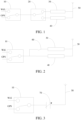
- FIG. 1 is a schematic structural diagram of an antenna 50 device provided in a first embodiment of the present application, including: an antenna 50, an antenna switching apparatus, a first matching circuit 40, and a second matching circuit 30.
- the first matching circuit 40 and the second matching circuit 30 are connected to the antenna 50, and the antenna switching apparatus is connected to the first matching circuit 40 and the second matching circuit 30.
- the working frequency band of the first matching circuit 40 is the frequency band corresponding to the GPS signal
- the working frequency band of the second matching circuit 30 is the frequency band corresponding to the wifi signal. Understandably, in some other embodiments, it may also include that: the working frequency band of the first matching circuit 40 is the frequency band corresponding to the wifi signal, and the working frequency band of the second matching circuit 30 is the frequency band corresponding to the GPS signal.
- the antenna switching apparatus includes: a first switch 10 and a second switch 20.
- the first switch 10 is connected to the transmission lines of the working frequency-band signals of the first matching circuit and the second matching circuit 30.
- the first switch 10 is connected to the second switch 20, and the second switch 20 is connected to the first matching circuit 40 and the second matching circuit 30.
- the working frequency-band signal of the first matching circuit 40 is used for a GPS signal to work indoors, and the working frequency-band signal of the second matching circuit 30 is used for a wifi signal to work outdoors, thereby ensuring that the working frequency-band signals of the first matching circuit 40 and the second matching circuit 30 can be used normally in different scenarios, and the performance of the antenna 50 is effectively improved.
- the working frequency-band signal of the first matching circuit 40 is preferentially transmitted.
- only one matching circuit in the first matching circuit 40 and the second matching circuit 30 is in working state.
- the beneficial effects of the first embodiment of the present application include that: The working frequency-band signals of the first matching circuit and the second matching circuit on the antenna are switched by the antenna switching apparatus to be used at staggered times. Therefore, it is ensured that the working frequency-band signals of the first matching circuit and the second matching circuit can be used normally in different scenarios, and the performance of the antenna is effectively improved.
- FIG. 2 is a schematic structural diagram of an antenna 50 device provided in a second embodiment of the present application, including: an antenna 50, an antenna switching apparatus, a first matching circuit 40, and a second matching circuit 30.
- the first matching circuit 40 and the second matching circuit 30 are connected to the antenna 50.
- the antenna switching apparatus is connected to the first matching circuit 40 and the second matching circuit 30.
- the working frequency band of the first matching circuit 40 is the frequency band corresponding to the GPS signal
- the working frequency band of the second matching circuit 30 is the frequency band corresponding to the wifi signal.
- the antenna switching apparatus further includes: a first switch 10 and a switch 60.
- the first switch 10 is connected to the transmission line of the working frequency-band signal of the first matching circuit and the second matching circuit
- the switch 60 is connected to the second matching circuit 30, and the first matching circuit 40 and the second matching circuit 30 are connected in parallel.
- the working frequency-band signal of the first matching circuit 40 is used for the GPS signal to work indoors, and the working frequency-band signal of the second matching circuit 30 is used for the wifi signal to work outdoors. Therefore, it is ensured that the working frequency-band signals of the first matching circuit 40 and the second matching circuit 30 can be used normally in different scenarios, and the performance of the antenna 50 is effectively improved.
- the working frequency-band signal of the first matching circuit 40 is preferentially transmitted.
- only one matching circuit in the first matching circuit 40 and the second matching circuit 30 is in working state.
- the beneficial effects of the second embodiment of the present application include that: The working frequency-band signals of the first matching circuit and the second matching circuit on the antenna are switched by the antenna switching apparatus so as to be used at staggered times. Therefore, it is ensured that the working frequency-band signals of the first matching circuit and the second matching circuit can be used normally in different scenarios, and the performance of the antenna is effectively improved.
- FIG. 3 is a schematic structural diagram of an antenna 50 device provided in a third embodiment of the present application, including: an antenna 50, an antenna switching apparatus, a first matching circuit 40, and a second matching circuit 30.
- the first matching circuit 40 and the second matching circuit 30 are connected to the antenna 50.
- the antenna switching apparatus is connected to the first matching circuit 40 and the second matching circuit 30.
- the working frequency band of the first matching circuit 40 is the frequency band corresponding to the GPS signal
- the working frequency band of the second matching circuit 30 is the frequency band corresponding to the wifi signal.
- the antenna switching apparatus includes: a first switch 10 and an adjustable capacitor 70.
- the first switch 10 is connected to the transmission lines of the working frequency-band signals of the first matching circuit and the second matching circuit.
- the adjustable capacitor 70 is connected to the first switch 10.
- the antenna resonant frequency is tuned according to the capacitance change of the adjustable capacitor 70, so as to adjust the working frequency-band signals of the first matching circuit 30 and the second matching circuit 40.
- the working frequency-band signal of the first matching circuit 40 is used for the GPS signal to work indoors, and the working frequency-band signal of the second matching circuit 30 is used for the wifi signal to work outdoors. Therefore, it is ensured that the working frequency-band signals of the first matching circuit 40 and the second matching circuit 30 can be used normally in different scenarios, and the performance of the antenna 50 is effectively improved.
- the working frequency-band signal of the first matching circuit 40 is preferentially transmitted.
- only one matching circuit in the first matching circuit 40 and the second matching circuit 30 is in working state.
- the beneficial effects of the third embodiment of the present application include that: The working frequency-band signals of the first matching circuit and the second matching circuit on the antenna are switched by the antenna switching apparatus so as to be used at staggered times. Therefore, it is ensured that the working frequency-band signals of the first matching circuit and the second matching circuit can be used normally in different scenarios, and the performance of the antenna is effectively improved.
- the embodiment of the present application also provides a mobile terminal 300.
- the mobile terminal 300 may be a device such as a smart phone or a tablet computer, specifically, as shown in FIG. 4 .
- Memory 320 may include a high-speed random access memory, and may also include a non-volatile memory such as one or more magnetic storage devices, flash memory, or other non-volatile solid-state memory. In some examples, the memory 320 may further include memories located remotely from a processor 380. These remote memories may be connected to the mobile terminal 300 through a network. Examples of the aforementioned networks include, but are not limited to, the Internet, intranets, local area networks, mobile communication networks, and combinations thereof.
- the input unit 330 can be used to receive input digital or character information, and the input unit 330 can generate keyboard, mouse, joystick, optical or trackball signal input related to user setting and function control.
- the input unit 330 may include a touch-sensitive surface 331 and other input device 332.
- the touch-sensitive surface 331 also referred to as a touch screen or touchpad, can collect user touch operations on or near it (for example, the user uses any suitable object or accessory such as a finger, a stylus, etc. on the touch-sensitive surface 331 or on the operation near the touch-sensitive surface 331), and drive the corresponding connection device according to the preset program.
- the touch-sensitive surface 331 may include two parts: a touch detection device and a touch controller.
- the touch detection device detects the orientation of the user's touch, detects the signal brought by the touch operation, and transmits the signal to the touch controller.
- the touch controller receives touch information from the touch detection device, converts it into contact coordinates, and then sends it to the processor 380, and can receive and execute commands sent by the processor 380.
- the touch-sensitive surface 331 may be implemented in various types such as resistive, capacitive, infrared, and surface acoustic wave.
- the input unit 330 may also include other input devices 332.
- other input devices 332 may include, but are not limited to, one or more of physical keyboards, function keys (such as volume control keys, switch keys, etc.), trackballs, mice, joysticks, and the like.
- the display unit 340 may be used to display information input by or provided to the user and various graphical user interfaces of the mobile terminal 300. These graphical user interfaces can be composed of graphics, text, icons, videos and any combination thereof.
- the display unit 340 may include a display panel 341.
- the display panel 341 may be configured in a form of LCD (liquid crystal display), OLED (organic light-emitting diode), or the like.
- the touch-sensitive surface 331 can cover the display panel 341. When the touch-sensitive surface 331 detects a touch operation on or near it, it transmits to the processor 380 to determine the type of the touch event. Then the processor 380 provides corresponding visual output on the display panel 341 according to the type of the touch event.
- the touch-sensitive surface 331 and the display panel 341 are used as two independent components to realize input and output functions, in some embodiments, the touch-sensitive surface 331 can be integrated with the display panel 341 for input and output functions.
- the mobile terminal 300 may also include at least one sensor 350, such as a light sensor, a motion sensor, and other sensors.
- the light sensor may include an ambient light sensor and a proximity sensor.
- the ambient light sensor can adjust the brightness of the display panel 341 according to the brightness of the ambient light.
- the proximity sensor can turn off the display panel 341 and/or the backlight when the mobile terminal 300 is moved to the ear.
- the gravity acceleration sensor can detect the magnitude of acceleration in all directions (generally three axes). It can detect the magnitude and direction of gravity when it is stationary, and can be used for applications that recognize the posture of the mobile phone (such as horizontal and vertical screen switching, related games, magnetometer posture calibration), vibration recognition related functions (such as pedometer, tap), etc.
- sensors such as a gyroscope, a barometer, a hygrometer, a thermometer, and an infrared sensor that can be configured on the mobile terminal 300, details will not be repeated here.
- the audio circuit 360, the speaker 361 and the microphone 362 can provide an audio interface between the user and the mobile terminal 300.
- the audio circuit 360 can transmit the electrical signal converted from the received audio data to the speaker 361, and the speaker 361 converts it into an audio signal for output.
- the microphone 362 converts the collected sound signal into an electrical signal, which is converted into audio data after being received by the audio circuit 360.
- the audio data is processed by the output processor 380, it is sent to another terminal through the RF circuit 310, for example.
- the audio data is output to the memory 320 for further processing.
- the audio circuit 360 may also include an earphone jack to provide communication between an external earphone and the mobile terminal 300.
- the processor 380 is the control center of the mobile terminal 300 and uses various interfaces and lines to connect various parts of the entire mobile phone. By running or executing software programs and/or modules stored in the memory 320, and calling data stored in the memory 320, various functions of the mobile terminal 300 are executed and data is processed, so as to monitor the mobile phone as a whole.
- the processor 380 may include one or more processing cores.
- the processor 380 may integrate an application processor and a modem processor.
- the application processor mainly handles the operating system, user interface and application programs, etc.
- the modem processor mainly handles wireless communication. It can be understood that the foregoing modem processor may not be integrated into the processor 380.
- the mobile terminal 300 further includes a power supply 390 (such as a battery) for powering various components.
- the power supply can be logically connected to the processor 380 through a power management system, so that functions such as charging, discharging, and power consumption management can be implemented through the power management system.
- the power supply 390 may also include one or more DC or AC power supplies, recharging systems, power failure detection circuits, power converters or inverters, power status indicators, and other arbitrary components.
- the mobile terminal 300 may also include a camera (such as a front camera, a rear camera), a Bluetooth module, etc., which will not be repeated here.
- a camera such as a front camera, a rear camera
- a Bluetooth module etc., which will not be repeated here.
- each of the above modules may be implemented as an independent entity or may be combined arbitrarily to be implemented as the same or several entities.
Landscapes
- Engineering & Computer Science (AREA)
- Computer Networks & Wireless Communication (AREA)
- Signal Processing (AREA)
- Telephone Function (AREA)
- Transceivers (AREA)
Abstract
Description
- This application claims priority to
Chinese Patent Application No. 202011350394.5, filed on November 26, 2020 - The present application relates to the technical field of mobile communication, and in particular to an antenna apparatus and a mobile terminal.
- More and more mobile terminals currently on the market support GPS L5 (1176.45 MHz) frequency band and WiFi MIMO function. Such devices are usually 5G mobile terminals, and a large number of antennas need to be arranged inside the mobile terminal, therefore, the space for antennas is becoming increasingly insufficient. In addition, most of the antennas in the mobile terminal can only debug a single resonance (meaning that the resonance has a good efficiency, such as >20%) due to insufficient size and length or the inability to route wires. Furthermore, the space of a multi-frequency antenna is larger than that of a single-frequency antenna.
- In addition, in mobile terminals, GPS L5 frequency band and WiFi MIMO function usually only play an auxiliary role, or signal enhancements to existing features. Therefore, when the antenna space is allocated, the headroom given is relatively small, and the debuggability is relatively poor.
- Embodiments of the present application provide an antenna apparatus and a mobile terminal to solve an issue of relatively poor debuggability of multi-frequency antennas in the case of a small clear space.
- According to one aspect of the present application, an embodiment of the present application provides an antenna apparatus, including: an antenna; a first matching circuit and a second matching circuit, wherein the first matching circuit and the second matching circuit are connected to the antenna; and an antenna switching apparatus connected to the first matching circuit and the second matching circuit; wherein at the same time, only one matching circuit in the first matching circuit and the second matching circuit is in a working state. Further, a working frequency band of the first matching circuit is used for a GPS signal; and a working frequency band of the second matching circuit is used for a wifi signal.
- Further, a working frequency band of the first matching circuit is a frequency band corresponding to a GPS signal; and a working frequency band of the second matching circuit is a frequency band corresponding to a wifi signal.
- Further, a working frequency-band signal of the first matching circuit is used for the GPS signal to work indoors; and a working frequency-band signal of the second matching circuit is used for a wifi signal to work outdoors.
- Further, a first switch; wherein the first switch is connected to transmission lines of working frequency-band signals of the first matching circuit and the second matching circuit.
- Further, the antenna switching apparatus further comprises: a second switch, wherein the second switch is connected to the first switch, and the second switch is respectively connected to the first matching circuit and the second matching circuit.
- Further, the antenna switching apparatus further comprises: a switch connected to the second matching circuit; wherein the first matching circuit and the second matching circuit are connected in parallel.
- Further, the antenna switching apparatus further comprises: an adjustable capacitor connected to the first switch; wherein an antenna resonant frequency is tuned according to a capacitance change of the adjustable capacitor, so as to adjust the working frequency-band signals of the first matching circuit and the second matching circuit.
- Further, the working frequency bands of the first matching circuit and the second matching circuit are adjusted through the adjustable capacitor.
- Further, when the working frequency-band signals of the first matching circuit and the second matching circuit exist at the same time, a working priority of the first matching circuit is higher than a working priority of the second matching circuit.
- According to another aspect of the present application, the present application provides a mobile terminal, including the above antenna apparatus.
- The present application provides a data acquisition method and system, a storage medium, and a mobile terminal. The beneficial effect of this application includes that: The working frequency-band signals of the first matching circuit and the second matching circuit on the antenna are switched by the antenna switching apparatus so as to be used at staggered times. Therefore, it is ensured that the working frequency-band signals of the first matching circuit and the second matching circuit can be used normally in different scenarios, and the performance of the antenna is effectively improved.
- In order to illustrate the technical solutions in the embodiments of the present invention more clearly, the following will briefly introduce the drawings that need to be used in the description of the embodiments. Obviously, the drawings in the following description are only some embodiments of the present invention. For those skilled in the art, other drawings can also be obtained based on these drawings without any creative effort.
-
FIG. 1 is a schematic structural diagram of an antenna apparatus provided in a first embodiment of the present application. -
FIG. 2 is a schematic structural diagram of an antenna apparatus provided in a second embodiment of the present application. -
FIG. 3 is a schematic structural diagram of an antenna apparatus provided in a third embodiment of the present application. -
FIG. 4 is a schematic structural diagram of a mobile terminal provided by an embodiment of the present application. - The following will clearly and completely describe the technical solutions in the embodiments of the present invention with reference to the drawings in the embodiments of the present invention. Apparently, the described embodiments are only some of the embodiments of the present invention, but not all of them. Based on the embodiments of the present invention, all other embodiments obtained by those skilled in the art without creative efforts fall within the protection scope of the present invention.
- As shown in
FIG. 1 , which is a schematic structural diagram of anantenna 50 device provided in a first embodiment of the present application, including: anantenna 50, an antenna switching apparatus, afirst matching circuit 40, and asecond matching circuit 30. - The
first matching circuit 40 and thesecond matching circuit 30 are connected to theantenna 50, and the antenna switching apparatus is connected to thefirst matching circuit 40 and thesecond matching circuit 30. - The working frequency band of the
first matching circuit 40 is the frequency band corresponding to the GPS signal, and the working frequency band of thesecond matching circuit 30 is the frequency band corresponding to the wifi signal. Understandably, in some other embodiments, it may also include that: the working frequency band of thefirst matching circuit 40 is the frequency band corresponding to the wifi signal, and the working frequency band of thesecond matching circuit 30 is the frequency band corresponding to the GPS signal. - In the first embodiment, the antenna switching apparatus includes: a
first switch 10 and asecond switch 20. Thefirst switch 10 is connected to the transmission lines of the working frequency-band signals of the first matching circuit and thesecond matching circuit 30. Thefirst switch 10 is connected to thesecond switch 20, and thesecond switch 20 is connected to thefirst matching circuit 40 and thesecond matching circuit 30. - The working frequency-band signal of the
first matching circuit 40 is used for a GPS signal to work indoors, and the working frequency-band signal of thesecond matching circuit 30 is used for a wifi signal to work outdoors, thereby ensuring that the working frequency-band signals of thefirst matching circuit 40 and thesecond matching circuit 30 can be used normally in different scenarios, and the performance of theantenna 50 is effectively improved. - When the working frequency-band signals of the
first matching circuit 40 and thesecond matching circuit 30 exist at the same time, the working frequency-band signal of thefirst matching circuit 40 is preferentially transmitted. At the same time, only one matching circuit in thefirst matching circuit 40 and thesecond matching circuit 30 is in working state. - The beneficial effects of the first embodiment of the present application include that: The working frequency-band signals of the first matching circuit and the second matching circuit on the antenna are switched by the antenna switching apparatus to be used at staggered times. Therefore, it is ensured that the working frequency-band signals of the first matching circuit and the second matching circuit can be used normally in different scenarios, and the performance of the antenna is effectively improved.
- As shown in
FIG. 2 , which is a schematic structural diagram of anantenna 50 device provided in a second embodiment of the present application, including: anantenna 50, an antenna switching apparatus, afirst matching circuit 40, and asecond matching circuit 30. - The
first matching circuit 40 and thesecond matching circuit 30 are connected to theantenna 50. In other words, the antenna switching apparatus is connected to thefirst matching circuit 40 and thesecond matching circuit 30. - The working frequency band of the
first matching circuit 40 is the frequency band corresponding to the GPS signal, and the working frequency band of thesecond matching circuit 30 is the frequency band corresponding to the wifi signal. - In the second embodiment, the antenna switching apparatus further includes: a
first switch 10 and aswitch 60. Thefirst switch 10 is connected to the transmission line of the working frequency-band signal of the first matching circuit and the second matching circuit, theswitch 60 is connected to thesecond matching circuit 30, and thefirst matching circuit 40 and thesecond matching circuit 30 are connected in parallel. - The working frequency-band signal of the
first matching circuit 40 is used for the GPS signal to work indoors, and the working frequency-band signal of thesecond matching circuit 30 is used for the wifi signal to work outdoors. Therefore, it is ensured that the working frequency-band signals of thefirst matching circuit 40 and thesecond matching circuit 30 can be used normally in different scenarios, and the performance of theantenna 50 is effectively improved. - When the working frequency-band signals of the
first matching circuit 40 and thesecond matching circuit 30 exist at the same time, the working frequency-band signal of thefirst matching circuit 40 is preferentially transmitted. At the same time, only one matching circuit in thefirst matching circuit 40 and thesecond matching circuit 30 is in working state. - The beneficial effects of the second embodiment of the present application include that: The working frequency-band signals of the first matching circuit and the second matching circuit on the antenna are switched by the antenna switching apparatus so as to be used at staggered times. Therefore, it is ensured that the working frequency-band signals of the first matching circuit and the second matching circuit can be used normally in different scenarios, and the performance of the antenna is effectively improved.
- As shown in
FIG. 3 , which is a schematic structural diagram of anantenna 50 device provided in a third embodiment of the present application, including: anantenna 50, an antenna switching apparatus, afirst matching circuit 40, and asecond matching circuit 30. - The
first matching circuit 40 and thesecond matching circuit 30 are connected to theantenna 50. In other words, the antenna switching apparatus is connected to thefirst matching circuit 40 and thesecond matching circuit 30. - The working frequency band of the
first matching circuit 40 is the frequency band corresponding to the GPS signal, and the working frequency band of thesecond matching circuit 30 is the frequency band corresponding to the wifi signal. - In the third embodiment, the antenna switching apparatus includes: a
first switch 10 and anadjustable capacitor 70. Thefirst switch 10 is connected to the transmission lines of the working frequency-band signals of the first matching circuit and the second matching circuit. - The
adjustable capacitor 70 is connected to thefirst switch 10. The antenna resonant frequency is tuned according to the capacitance change of theadjustable capacitor 70, so as to adjust the working frequency-band signals of thefirst matching circuit 30 and thesecond matching circuit 40. - The working frequency-band signal of the
first matching circuit 40 is used for the GPS signal to work indoors, and the working frequency-band signal of thesecond matching circuit 30 is used for the wifi signal to work outdoors. Therefore, it is ensured that the working frequency-band signals of thefirst matching circuit 40 and thesecond matching circuit 30 can be used normally in different scenarios, and the performance of theantenna 50 is effectively improved. - When the working frequency-band signals of the
first matching circuit 40 and thesecond matching circuit 30 exist at the same time, the working frequency-band signal of thefirst matching circuit 40 is preferentially transmitted. At the same time, only one matching circuit in thefirst matching circuit 40 and thesecond matching circuit 30 is in working state. - The beneficial effects of the third embodiment of the present application include that: The working frequency-band signals of the first matching circuit and the second matching circuit on the antenna are switched by the antenna switching apparatus so as to be used at staggered times. Therefore, it is ensured that the working frequency-band signals of the first matching circuit and the second matching circuit can be used normally in different scenarios, and the performance of the antenna is effectively improved.
- The embodiment of the present application also provides a
mobile terminal 300. Themobile terminal 300 may be a device such as a smart phone or a tablet computer, specifically, as shown inFIG. 4 . -
Memory 320 may include a high-speed random access memory, and may also include a non-volatile memory such as one or more magnetic storage devices, flash memory, or other non-volatile solid-state memory. In some examples, thememory 320 may further include memories located remotely from aprocessor 380. These remote memories may be connected to themobile terminal 300 through a network. Examples of the aforementioned networks include, but are not limited to, the Internet, intranets, local area networks, mobile communication networks, and combinations thereof. - The
input unit 330 can be used to receive input digital or character information, and theinput unit 330 can generate keyboard, mouse, joystick, optical or trackball signal input related to user setting and function control. Specifically, theinput unit 330 may include a touch-sensitive surface 331 andother input device 332. The touch-sensitive surface 331, also referred to as a touch screen or touchpad, can collect user touch operations on or near it (for example, the user uses any suitable object or accessory such as a finger, a stylus, etc. on the touch-sensitive surface 331 or on the operation near the touch-sensitive surface 331), and drive the corresponding connection device according to the preset program. Optionally, the touch-sensitive surface 331 may include two parts: a touch detection device and a touch controller. The touch detection device detects the orientation of the user's touch, detects the signal brought by the touch operation, and transmits the signal to the touch controller. The touch controller receives touch information from the touch detection device, converts it into contact coordinates, and then sends it to theprocessor 380, and can receive and execute commands sent by theprocessor 380. In addition, the touch-sensitive surface 331 may be implemented in various types such as resistive, capacitive, infrared, and surface acoustic wave. In addition to the touch-sensitive surface 331, theinput unit 330 may also includeother input devices 332. Specifically,other input devices 332 may include, but are not limited to, one or more of physical keyboards, function keys (such as volume control keys, switch keys, etc.), trackballs, mice, joysticks, and the like. - The
display unit 340 may be used to display information input by or provided to the user and various graphical user interfaces of themobile terminal 300. These graphical user interfaces can be composed of graphics, text, icons, videos and any combination thereof. Thedisplay unit 340 may include adisplay panel 341. Optionally, thedisplay panel 341 may be configured in a form of LCD (liquid crystal display), OLED (organic light-emitting diode), or the like. Further, the touch-sensitive surface 331 can cover thedisplay panel 341. When the touch-sensitive surface 331 detects a touch operation on or near it, it transmits to theprocessor 380 to determine the type of the touch event. Then theprocessor 380 provides corresponding visual output on thedisplay panel 341 according to the type of the touch event. Although inFIG. 4 , the touch-sensitive surface 331 and thedisplay panel 341 are used as two independent components to realize input and output functions, in some embodiments, the touch-sensitive surface 331 can be integrated with thedisplay panel 341 for input and output functions. - The
mobile terminal 300 may also include at least onesensor 350, such as a light sensor, a motion sensor, and other sensors. Specifically, the light sensor may include an ambient light sensor and a proximity sensor. The ambient light sensor can adjust the brightness of thedisplay panel 341 according to the brightness of the ambient light. The proximity sensor can turn off thedisplay panel 341 and/or the backlight when themobile terminal 300 is moved to the ear. As a kind of motion sensor, the gravity acceleration sensor can detect the magnitude of acceleration in all directions (generally three axes). It can detect the magnitude and direction of gravity when it is stationary, and can be used for applications that recognize the posture of the mobile phone (such as horizontal and vertical screen switching, related games, magnetometer posture calibration), vibration recognition related functions (such as pedometer, tap), etc. As for other sensors such as a gyroscope, a barometer, a hygrometer, a thermometer, and an infrared sensor that can be configured on themobile terminal 300, details will not be repeated here. - The
audio circuit 360, thespeaker 361 and themicrophone 362 can provide an audio interface between the user and themobile terminal 300. Theaudio circuit 360 can transmit the electrical signal converted from the received audio data to thespeaker 361, and thespeaker 361 converts it into an audio signal for output. On the other hand, themicrophone 362 converts the collected sound signal into an electrical signal, which is converted into audio data after being received by theaudio circuit 360. After the audio data is processed by theoutput processor 380, it is sent to another terminal through theRF circuit 310, for example. Alternatively, the audio data is output to thememory 320 for further processing. Theaudio circuit 360 may also include an earphone jack to provide communication between an external earphone and themobile terminal 300. - The
processor 380 is the control center of themobile terminal 300 and uses various interfaces and lines to connect various parts of the entire mobile phone. By running or executing software programs and/or modules stored in thememory 320, and calling data stored in thememory 320, various functions of themobile terminal 300 are executed and data is processed, so as to monitor the mobile phone as a whole. Optionally, theprocessor 380 may include one or more processing cores. In some embodiments, theprocessor 380 may integrate an application processor and a modem processor. The application processor mainly handles the operating system, user interface and application programs, etc., and the modem processor mainly handles wireless communication. It can be understood that the foregoing modem processor may not be integrated into theprocessor 380. - The
mobile terminal 300 further includes a power supply 390 (such as a battery) for powering various components. In some embodiments, the power supply can be logically connected to theprocessor 380 through a power management system, so that functions such as charging, discharging, and power consumption management can be implemented through the power management system. Thepower supply 390 may also include one or more DC or AC power supplies, recharging systems, power failure detection circuits, power converters or inverters, power status indicators, and other arbitrary components. - Although not shown, the
mobile terminal 300 may also include a camera (such as a front camera, a rear camera), a Bluetooth module, etc., which will not be repeated here. - During specific implementation, each of the above modules may be implemented as an independent entity or may be combined arbitrarily to be implemented as the same or several entities. For the specific implementation of the above modules, reference may be made to the foregoing method embodiments, and details are not repeated here.
- In this description, specific examples are used to illustrate the principles and implementation methods of the present application, and the descriptions of the above embodiments are only used to help understand the technical solutions and core ideas of the present application. Those of ordinary skill in the art should understand that they can still modify the technical solutions described in the foregoing embodiments or perform equivalent replacements for some of the technical features. However, these modifications or replacements do not make the essence of the corresponding technical solutions depart from the scope of the technical solutions of the embodiments of the present application.
Claims (10)
- An antenna apparatus, comprising:an antenna;a first matching circuit and a second matching circuit, wherein the first matching circuit and the second matching circuit are connected to the antenna; andan antenna switching apparatus connected to the first matching circuit and the second matching circuit;wherein at the same time, only one matching circuit in the first matching circuit and the second matching circuit is in a working state.
- The antenna apparatus of claim 1, wherein a working frequency band of the first matching circuit is a frequency band corresponding to a GPS signal; and
a working frequency band of the second matching circuit is a frequency band corresponding to a wifi signal. - The antenna apparatus of claim 1, wherein a working frequency-band signal of the first matching circuit is used for the GPS signal to work indoors; and
a working frequency-band signal of the second matching circuit is used for a wifi signal to work outdoors. - The antenna apparatus of claim 1, wherein the antenna switching apparatus comprises:a first switch;wherein the first switch is connected to transmission lines of working frequency-band signals of the first matching circuit and the second matching circuit.
- The antenna apparatus of claim 4, wherein the antenna switching apparatus further comprises: a second switch, wherein the second switch is connected to the first switch, and the second switch is respectively connected to the first matching circuit and the second matching circuit.
- The antenna apparatus of claim 4, wherein the antenna switching apparatus further comprises: a switch connected to the second matching circuit;
wherein the first matching circuit and the second matching circuit are connected in parallel. - The antenna apparatus of claim 4, wherein the antenna switching apparatus further comprises: an adjustable capacitor connected to the first switch;
wherein an antenna resonant frequency is tuned according to a capacitance change of the adjustable capacitor, so as to adjust the working frequency-band signals of the first matching circuit and the second matching circuit. - The antenna apparatus of claim 7, wherein the working frequency bands of the first matching circuit and the second matching circuit are adjusted through the adjustable capacitor.
- The antenna apparatus of claim 1, wherein when the working frequency-band signals of the first matching circuit and the second matching circuit exist at the same time, a working priority of the first matching circuit is higher than a working priority of the second matching circuit.
- A mobile terminal, comprising the antenna apparatus of claim 1.
Applications Claiming Priority (2)
| Application Number | Priority Date | Filing Date | Title |
|---|---|---|---|
| CN202011350394.5A CN112532273A (en) | 2020-11-26 | 2020-11-26 | Antenna device and mobile terminal |
| PCT/CN2020/134906 WO2022110309A1 (en) | 2020-11-26 | 2020-12-09 | Antenna apparatus and mobile terminal |
Publications (2)
| Publication Number | Publication Date |
|---|---|
| EP4254813A1 true EP4254813A1 (en) | 2023-10-04 |
| EP4254813A4 EP4254813A4 (en) | 2024-10-23 |
Family
ID=74993859
Family Applications (1)
| Application Number | Title | Priority Date | Filing Date |
|---|---|---|---|
| EP20963197.7A Pending EP4254813A4 (en) | 2020-11-26 | 2020-12-09 | Antenna apparatus and mobile terminal |
Country Status (4)
| Country | Link |
|---|---|
| US (1) | US12525716B2 (en) |
| EP (1) | EP4254813A4 (en) |
| CN (1) | CN112532273A (en) |
| WO (1) | WO2022110309A1 (en) |
Family Cites Families (23)
| Publication number | Priority date | Publication date | Assignee | Title |
|---|---|---|---|---|
| US6816711B2 (en) | 2001-11-27 | 2004-11-09 | Qualcomm Incorporated | GPS equipped mobile phone with single shared antenna |
| KR20040023423A (en) * | 2002-09-11 | 2004-03-18 | 엘지전자 주식회사 | Antenna embedded mobile information terminal and method for his using message |
| KR100531879B1 (en) | 2003-07-09 | 2005-11-29 | 엘지전자 주식회사 | Radio frequency reception circuit for mobile phone |
| CN1615039A (en) * | 2003-11-06 | 2005-05-11 | 明基电通股份有限公司 | Switchable Antenna Matching System for Clamshell Mobile Devices |
| CN101646030A (en) * | 2009-05-15 | 2010-02-10 | 上海闻泰电子科技有限公司 | Circuit designing method for extending antenna bandwidth of analogue television |
| CN101562460B (en) | 2009-05-22 | 2013-04-03 | 惠州Tcl移动通信有限公司 | Wireless receiving and emitting device of mobile communication terminal |
| CN201805459U (en) * | 2010-09-17 | 2011-04-20 | 惠州Tcl移动通信有限公司 | Mobile phone device |
| CN201947322U (en) * | 2011-01-11 | 2011-08-24 | 惠州Tcl移动通信有限公司 | Mobile phone |
| CN102637964A (en) * | 2012-04-28 | 2012-08-15 | 上海华勤通讯技术有限公司 | Antenna system and mobile terminal thereof |
| TWI578621B (en) * | 2012-11-29 | 2017-04-11 | 群邁通訊股份有限公司 | Near field communication and frequency modulation antenna system |
| CN104184488A (en) * | 2013-05-27 | 2014-12-03 | 深圳富泰宏精密工业有限公司 | Radio frequency matching circuit and wireless communication apparatus |
| CN203466293U (en) * | 2013-08-28 | 2014-03-05 | 深圳富泰宏精密工业有限公司 | Antenna assembly |
| CN104795636A (en) * | 2014-01-22 | 2015-07-22 | 联想(北京)有限公司 | Antenna device, electronic equipment and antenna device setting method |
| CN204991941U (en) * | 2015-07-24 | 2016-01-20 | 歌尔声学股份有限公司 | Wearable terminal |
| CN107947822B (en) * | 2016-10-13 | 2021-08-24 | 中兴通讯股份有限公司 | Antenna matching circuit, frequency band selection method and device |
| CN106711612B (en) * | 2016-12-23 | 2023-10-13 | 歌尔科技有限公司 | Antenna double-working-frequency switching circuit and electronic equipment |
| WO2018120773A1 (en) | 2016-12-28 | 2018-07-05 | Guangdong Oppo Mobile Telecommunications Corp., Ltd. | Antenna device for mobile terminal and mobile terminal |
| JP7038483B2 (en) * | 2017-04-11 | 2022-03-18 | 株式会社デンソーテン | Antenna amplifier unit and receiving system |
| CN108134202B (en) | 2017-12-14 | 2020-03-10 | Oppo广东移动通信有限公司 | Antenna tuning circuit and mobile terminal |
| KR102618860B1 (en) * | 2019-02-19 | 2023-12-28 | 삼성전자주식회사 | Antenna and electronic device having it |
| CN110311696A (en) * | 2019-06-26 | 2019-10-08 | 维沃移动通信有限公司 | A radio frequency circuit and terminal |
| CN111211421A (en) * | 2020-03-19 | 2020-05-29 | 惠州Tcl移动通信有限公司 | Antenna tuning circuit and mobile terminal |
| CN111710957A (en) * | 2020-06-28 | 2020-09-25 | 上海创功通讯技术有限公司 | Adjustable antenna and metal frame terminal equipment |
-
2020
- 2020-11-26 CN CN202011350394.5A patent/CN112532273A/en active Pending
- 2020-12-09 US US18/254,197 patent/US12525716B2/en active Active
- 2020-12-09 EP EP20963197.7A patent/EP4254813A4/en active Pending
- 2020-12-09 WO PCT/CN2020/134906 patent/WO2022110309A1/en not_active Ceased
Also Published As
| Publication number | Publication date |
|---|---|
| WO2022110309A1 (en) | 2022-06-02 |
| US12525716B2 (en) | 2026-01-13 |
| CN112532273A (en) | 2021-03-19 |
| EP4254813A4 (en) | 2024-10-23 |
| US20240006767A1 (en) | 2024-01-04 |
Similar Documents
| Publication | Publication Date | Title |
|---|---|---|
| US9024877B2 (en) | Method for automatically switching user interface of handheld terminal device, and handheld terminal device | |
| CN106791894B (en) | A kind of method and apparatus playing live video | |
| EP2851779A1 (en) | Method, device, storage medium and terminal for displaying a virtual keyboard | |
| CN108536411A (en) | A kind of method for controlling mobile terminal and mobile terminal | |
| CN111092621B (en) | Radio frequency circuit, control method and electronic equipment | |
| CN103389863A (en) | Display control method and device | |
| CN107609439A (en) | Method, device, storage medium and terminal for processing radio frequency interference | |
| CN106445339A (en) | Three-dimensional image display method and device for double-screen terminal | |
| CN111078108A (en) | Screen display method and device, storage medium and mobile terminal | |
| US11262911B2 (en) | Integrated home key and virtual key area for a smart terminal | |
| CN106371749A (en) | Method and device for terminal control | |
| CN106445340A (en) | Method and device for displaying stereoscopic image by double-screen terminal | |
| CN106487984A (en) | A kind of method and apparatus of adjustment volume | |
| CN111651387B (en) | Interface Circuits and Electronic Equipment | |
| CN108881558A (en) | Mobile terminal and its FM anti-jamming circuit | |
| CN108536349A (en) | A kind of icon management method and mobile terminal | |
| CN107967202B (en) | Folding screen opening and closing state determination method and mobile terminal | |
| CN105718141A (en) | Method for moving desktop icons and mobile terminal | |
| EP4134732A1 (en) | Electronic device and driving method therefor | |
| US12525716B2 (en) | Antenna apparatus and mobile terminal | |
| CN106341150A (en) | Carrier aggregation radio frequency circuit and mobile terminal | |
| CN111446986A (en) | Frame rate adjusting method and electronic equipment | |
| CN111026457A (en) | Hardware configuration method and device, storage medium and terminal equipment | |
| CN109638416B (en) | Antenna structure and electronic device | |
| CN110995324B (en) | Bluetooth communication method, device, storage medium and terminal equipment |
Legal Events
| Date | Code | Title | Description |
|---|---|---|---|
| STAA | Information on the status of an ep patent application or granted ep patent |
Free format text: STATUS: THE INTERNATIONAL PUBLICATION HAS BEEN MADE |
|
| PUAI | Public reference made under article 153(3) epc to a published international application that has entered the european phase |
Free format text: ORIGINAL CODE: 0009012 |
|
| STAA | Information on the status of an ep patent application or granted ep patent |
Free format text: STATUS: REQUEST FOR EXAMINATION WAS MADE |
|
| 17P | Request for examination filed |
Effective date: 20230621 |
|
| AK | Designated contracting states |
Kind code of ref document: A1 Designated state(s): AL AT BE BG CH CY CZ DE DK EE ES FI FR GB GR HR HU IE IS IT LI LT LU LV MC MK MT NL NO PL PT RO RS SE SI SK SM TR |
|
| DAV | Request for validation of the european patent (deleted) | ||
| DAX | Request for extension of the european patent (deleted) | ||
| A4 | Supplementary search report drawn up and despatched |
Effective date: 20240925 |
|
| RIC1 | Information provided on ipc code assigned before grant |
Ipc: H04B 1/00 20060101ALI20240919BHEP Ipc: H04B 1/401 20150101AFI20240919BHEP |