EP4254779A1 - Operation control system and air conditioner, operation control method, and operation control program - Google Patents
Operation control system and air conditioner, operation control method, and operation control program Download PDFInfo
- Publication number
- EP4254779A1 EP4254779A1 EP23153519.6A EP23153519A EP4254779A1 EP 4254779 A1 EP4254779 A1 EP 4254779A1 EP 23153519 A EP23153519 A EP 23153519A EP 4254779 A1 EP4254779 A1 EP 4254779A1
- Authority
- EP
- European Patent Office
- Prior art keywords
- period
- pulse
- mask period
- command
- generate
- Prior art date
- Legal status (The legal status is an assumption and is not a legal conclusion. Google has not performed a legal analysis and makes no representation as to the accuracy of the status listed.)
- Pending
Links
Images




Classifications
-
- H—ELECTRICITY
- H02—GENERATION; CONVERSION OR DISTRIBUTION OF ELECTRIC POWER
- H02P—CONTROL OR REGULATION OF ELECTRIC MOTORS, ELECTRIC GENERATORS OR DYNAMO-ELECTRIC CONVERTERS; CONTROLLING TRANSFORMERS, REACTORS OR CHOKE COILS
- H02P27/00—Arrangements or methods for the control of AC motors characterised by the kind of supply voltage
- H02P27/04—Arrangements or methods for the control of AC motors characterised by the kind of supply voltage using variable-frequency supply voltage, e.g. inverter or converter supply voltage
- H02P27/06—Arrangements or methods for the control of AC motors characterised by the kind of supply voltage using variable-frequency supply voltage, e.g. inverter or converter supply voltage using DC to AC converters or inverters
- H02P27/08—Arrangements or methods for the control of AC motors characterised by the kind of supply voltage using variable-frequency supply voltage, e.g. inverter or converter supply voltage using DC to AC converters or inverters with pulse width modulation
-
- H—ELECTRICITY
- H02—GENERATION; CONVERSION OR DISTRIBUTION OF ELECTRIC POWER
- H02P—CONTROL OR REGULATION OF ELECTRIC MOTORS, ELECTRIC GENERATORS OR DYNAMO-ELECTRIC CONVERTERS; CONTROLLING TRANSFORMERS, REACTORS OR CHOKE COILS
- H02P21/00—Arrangements or methods for the control of electric machines by vector control, e.g. by control of field orientation
Definitions
- the present disclosure relates to an operation control system and an air conditioner, an operation control method, and an operation control program.
- An air conditioner is primarily equipped with an inverter device that generates AC power for load (motor) drive to freely drive a motor of a compressor.
- An inverter device is well-known, which converts a three-phase AC voltage input from a commercial power supply (e.g., AC 200 V three-phase AC power supply) into a DC voltage once through a rectifier circuit (converter), and then converts the DC power into desired AC power for motor drive by the inverter device.
- a commercial power supply e.g., AC 200 V three-phase AC power supply
- Patent Document 1 in order to reduce switching loss in the inverter device, a PWM-controlled pulse signal is stopped for a certain period (mask period) (partial two-phase current control). Partial two-phase current control is also disclosed in Patent Documents 2 and 3.
- an object of the present disclosure is to provide an operation control system and an air conditioner, an operation control method, and an operation control program that can reduce loss and improve operation stability for motor.
- a first aspect of the present disclosure is an operation control system, which includes: a voltage command unit configured to generate sine wave voltage commands on the basis of a speed command for an AC motor; a command generation unit configured to, by using a predetermined angular range that includes an electrical angle at which the amplitude in the voltage commands is zero as a mask period, generate a command to: generate a pulse-width modulation (PWM) signal for the AC motor on the basis of the voltage commands during periods other than the mask period; and to generate, when the mask period is divided into a former-stage period and a latter-stage period, an additional pulse in at least one of the former-stage period and the latter-stage period; and a pulse generation unit configured to generate a pulse signal for a switching element that drives the AC motor on the basis of the command generated by the command generation unit.
- PWM pulse-width modulation
- a second aspect of the present disclosure is an operation control method, which includes: generating sine wave voltage commands on the basis of a speed command for an AC motor; generating, by using a predetermined angular range that includes an electrical angle at which the amplitude in the voltage commands is zero as a mask period, a command to: generate a pulse-width modulation signal for the AC motor on the basis of the voltage commands during periods other than the mask period; and to generate, when the mask period is divided into a former-stage period and a latter-stage period, an additional pulse in at least one of the former-stage period and the latter-stage period; and generating a pulse signal for a switching element that drives the AC motor on the basis of the command generated by using said predetermined angular range as the mask period.
- a third aspect of the present disclosure is an operation control program configured to cause a computer to execute: a step of generating sine wave voltage commands on the basis of a speed command for an AC motor; a step of generating, by using a predetermined angular range that includes an electrical angle at which the amplitude in the voltage commands is zero as a mask period, a command to: generate a pulse-width modulation signal for the AC motor on the basis of the voltage commands during periods other than the mask period; to generate, when the mask period is divided into a former-stage period and a latter-stage period, an additional pulse in at least one of the former-stage period and the latter-stage period; and a step of generating a pulse signal for a switching element configured to drive the AC motor on the basis of the command generated by using the predetermined angular range as the mask period.
- the effect of reducing loss and improving operation stability for a motor is achieved.
- FIG. 1 is a diagram illustrating a circuit configuration of an inverter device according to an embodiment.
- An inverter device 1 is installed in an outdoor unit of an air conditioner 90.
- the inverter device 1 outputs, to a three-phase AC motor (motor 80) for driving the compressor of the above-described outdoor unit, an AC voltage (three-phase AC voltage) for load driving in accordance with a separately input speed command.
- a three-phase AC motor is illustrated and described in the present embodiment, a wide range of AC motors can be applied.
- the inverter device 1 rotationally drives the three-phase AC motor (motor 80), that is, the load at a desired rotational speed on the basis of the AC voltage for load driving.
- the inverter device 1 includes a control device 10, an inverter main circuit 20, and a motor current detecting unit 30.
- the inverter device 1 converts a DC voltage Vdc supplied by a DC power supply PS into a three-phase AC voltage consisting of a U-phase AC voltage, a V-phase AC voltage, and a W-phase AC voltage, which are AC voltages for load driving to rotationally drive the motor 80.
- the motor current detecting unit 30 is provided on each of the wiring lines for the three phases connected from the inverter device 1 to the motor 80.
- the motor current detecting unit 30 detects currents iu, iv, and iw of the U-phase, the V-phase, and the W-phase flowing through the motor 80 in relation to the three-phase applied voltage (AC voltage vu, vv, vw) output from the inverter device 1 to the motor 80, respectively, and notifies the control device 10 of the detection result of each current iu, iv, and iw.
- the inverter main circuit 20 includes a switching element group 21, a positive electrode DC terminal Qa, and a negative electrode DC terminal Qb.
- the positive electrode DC terminal Qa and the negative electrode DC terminal Qb are terminals to which the DC voltage Vdc is input.
- the positive electrode DC terminal Qa and the negative electrode DC terminal Qb are connected to the positive and negative electrodes of the DC power supply PS, respectively.
- the switching element group 21 includes three pairs of two switching elements connected in series between the DC voltage Vdc.
- the switching element is, for example, a power transistor such as an Insulated Gate Bipolar Transistor (IGBT).
- IGBT Insulated Gate Bipolar Transistor
- the switching element group 21 includes a pair of an upper arm switching element 21 UH and a lower arm switching element 21UL connected in series, from the positive electrode DC terminal Qa to the negative electrode DC terminal Qb into which DC voltage Vdc is input.
- the switching element group 21 includes a pair of an upper arm switching element 21VH and a lower arm switching element 21VL connected in series from the positive electrode DC terminal Qa to the negative electrode DC terminal Qb.
- the switching element group 21 includes a pair of an upper arm switching element 21WH and a lower arm switching element 21WL connected in series from the positive electrode DC terminal Qa to the negative electrode DC terminal Qb.
- the pair of the upper arm switching element 21UH and the lower arm switching element 21UL are switched by a gate signal from a PWM generation unit 22 (described later) to generate an AC voltage vu in a U-phase.
- the pair of the upper arm switching element 21UH and the lower arm switching element 21UL are alternately switched in a region excluding a peak voltage region RGP and a zero voltage region RGZ.
- the pair of the upper arm switching element 21VH and the lower arm switching element 21VL are switched by the gate signal from the PWM generation unit 22 to generate an AC voltage vv in a V-phase.
- the pair of the upper arm switching element 21VH and the lower arm switching element 21VL are alternately switched in the region excluding the peak voltage region RGP and the zero voltage region RGZ.
- the pair of the upper arm switching element 21WH and the lower arm switching element 21WL are switched by the gate signal from the PWM generation unit 22 to generate an AC voltage vw in a W-phase.
- the pair of the upper arm switching element 21WH and the lower arm switching element 21WL are alternately switched in the region excluding the peak voltage region RGP and the zero voltage region RGZ.
- the PWM generation unit 22 generates a gate signal (PWM signal) to drive the switching element group 21 and turn the switching element group 21 on and off, in relation to a command (described later) received from a two-phase/three-phase conversion unit 13, which is provided in the control device 10.
- the PWM generation unit 22 acquires AC voltage commands vu*, vv*, vw*.
- the PWM generation unit 22 generates a PWM-controlled pulse signal (hereinafter also referred to as "PWM signal") with a duty rate proportional to the voltage of each waveform at each timing of the acquired AC voltage commands vu*, vv* and vw*.
- PWM signal a PWM-controlled pulse signal
- the PWM generation unit 22 outputs a gate signal SG (21UH), a gate signal SG (21UL), a gate signal SG (21VH), a gate signal SG (21VL), a gate signal SG (21WH), and a gate signal SG (21WL) to the gates of the switching element 21UH, the switching element 21UL, the switching element 21VH, the switching element 21VL, the switching element 21WH, and the switching element 21WL, respectively, which will be described later.
- the PWM generation unit 22 generates the gate signal SG (21UH) and the gate signal SG (21UL) on the basis of the AC voltage command vu*.
- the PWM generation unit 22 generates the gate signal SG (21VH) and the gate signal SG (21VL) on the basis of the AC voltage command vv*.
- the PWM generation unit 22 generates the gate signal SG (21WH) and the gate signal SG (21WL) on the basis of the AC voltage command vw*.
- the signals output from the PWM generation unit 22 are corrected as described below at a mask period generation unit 61 and a pulse addition unit 62, which will be described later.
- the control device 10 is functionally provided with a speed control unit 11, a current control unit 12, a two-phase/three-phase conversion unit 13, the PWM generation unit 22, and a command generation unit 71.
- the command generation unit 71 generates a command to generate a PWM signal on the basis of the voltage commands and generates an additional pulse during the mask period.
- the command generation unit 71 includes a mask period command unit 63 and a pulse addition command unit 64. Note that, the PWM generation unit 22, the mask period generation unit 61, and the pulse addition unit 62 constitute a pulse generation unit 72.
- a computer system functions as the control device 10 by executing a program described later.
- the speed control unit 11 outputs a speed command for rotating the motor 80 at a desired rotational speed ⁇ .
- the current control unit 12 receives input of a speed command from the speed control unit 11 and generates voltage commands on two axes (delta and gamma axes) of a rotating rectangular coordinate system on the basis of the current iu, iv, and iw detected at the motor current detecting unit 30. For example, the current control unit 12 generates and outputs a ⁇ axis voltage command and a ⁇ axis voltage command as voltage commands.
- the two-phase/three-phase conversion unit 13 performs coordinate conversion on the voltage command output from the current control unit 12 to AC voltage commands vu*, vv*, and vw* corresponding to each of the AC voltages of the three phases. In this way, with the current control unit 12 and the two-phase/three-phase conversion unit 13, a (similar) sine wave corresponding to each of the desired three-phase AC is output, and sine wave voltage commands are generated based on the speed command of the AC motor.
- a PWM signal is generated at the PWM generation unit 22 by comparing the voltage command with the voltage waveform of a reference triangular wave (or saw-shaped wave).
- a reference triangular wave or saw-shaped wave.
- the two-arm type control is control of turning on each switching element for a predetermined period of time. Specifically, in a large region (peak voltage region RGP) of (the absolute value of) each phase voltage of the three-phase AC voltage, the upper arm switching elements 21UH, 21VH, 21WH, and the lower arm switching elements 21UL, 21VL, 21WL are turned on (continuously-on) over all the multi-period regions of the PWM period.
- the control device 10 includes the mask period command unit 63 in order to reduce switching losses.
- the mask period (zero voltage region RGZ) is a period when the duty cycle is 0% (continuously-off) and all regions in the period have an off-signal (no pulse). In other words, PWM signals are stopped during the mask period.
- the mask period is set as a predetermined angular range that includes an electrical angle at which the amplitude in the voltage commands (AC voltage commands vu*, vv*, vw*) is zero.
- the angular range is, for example, 60 degrees.
- the mask period command unit 63 corrects the PWM signal such that the mask period is formed in a preset angular range. Specifically, the mask period command unit 63 outputs a command to a mask period generation unit 61 to correct the PWM signal generated at the PWM generation unit 22.
- the formation method of the mask period is not limited to the above method provided that the mask period can be formed.
- the mask period command unit 63 Multiple pulses during the mask period are removed by the mask period command unit 63. This suppresses switching losses. For example, in the U-phase, the current iu is kept in a state of substantially not flowing in all regions during the mask period. On the other hand, because the other phases are deviated from each other, the current iv of the V-phase and the current iw of the W-phase flow even during the mask period of the U-phase. That is, since the currents in these two phases partially flow, control that stops the current of a specific phase using a mask period (while currents in the other two phases flow) is called partial two-phase current control. In other words, the partial two-phase current control is control of, when generating PWM signals on the basis of the voltage commands vu*, vv*, and vw*, stopping the pulse of any one phase during the mask period.
- partial two-phase current control is possible.
- the PWM control suddenly stops and starts.
- motor torque may be insufficient and the waveform may be distorted. This can cause phenomena such as vibration, noise, or step-out.
- the control device 10 is provided with the pulse addition command unit 64. That is, the control device 10 and the PWM generation unit 22 constitute an operation control system that generates PWM signals for operation control.
- the pulse addition command unit 64 outputs a command to the pulse addition unit 62 to correct the PWM signal corrected by the mask period generation unit 61.
- a signal including an additional pulse AP generated during the mask period is output as a gate signal.
- PWM signals are generated on the basis of the voltage commands vu*, vv*, and vw*
- an additional pulse AP is generated not on the basis of the voltage commands vu*, vv*, and vw*. That is, the additional pulse AP is formed by the pulse addition command unit 64 during the mask period in which pulses are not generally formed. No pulse other than the additional pulse AP is formed during the mask period.
- the number of the additional pulses AP formed during the mask period is smaller than the number of PWM pulses that would have been formed during the mask period on the basis of the voltage commands vu*, vv*, and vw*.
- generated torque shock is considered to be small. Specifically, when the mask period is less than +/- 5 deg (i.e., less than 10 degs), the generated torque shock is minor and the additional pulse AP may be unnecessary. When the mask period is long, for example, +/- 20 deg (i.e., 40 deg ), the disturbance of the generated current waveform becomes large, which causes step-out and vibration.
- the additional pulse AP is preferably generated during the mask period when the mask period is +/-5 deg or greater.
- the additional pulse AP is generated during at least one of the former-stage period and the latter-stage period.
- the former-stage period is a former-stage of the mask period, including a start point of the mask period
- the latter-stage period is a latter-stage of the mask period, including an end point of the mask period.
- the former-stage period and the latter-stage period may be separated by a predetermined timing (e.g., the center) in the mask period or by an intermediate period including the center period in the mask period.
- a predetermined timing e.g., the center
- Providing the additional pulse AP in the former-stage period makes it possible to suppress the torque shock generated because of the stop of PWM control due to the start of the mask period.
- Providing the additional pulse AP in the latter-stage period makes it possible to suppress the torque shock generated because of the start of PWM control (start from stop) due to the end of the mask period.
- the additional pulse AP is generated during the former-stage period and not generated during the latter-stage period.
- the additional pulse AP is generated during the former-stage period and during the latter-stage period.
- FIG. 4 illustrates a waveform without a mask period, as a reference example.
- the period of M1 corresponds to the mask period.
- FIG. 5 illustrates an example of the case (1).
- the horizontal axis represents a phase ⁇ and the vertical axis represents voltage.
- FIG. 5 illustrates a case where the additional pulse AP is generated during the mask period M1 in the reference example of FIG. 4 . As illustrated in FIG. 5 , the additional pulse AP is generated during the former-stage period of the mask period and not generated during the latter-stage period.
- FIG. 6 illustrates an example of the case (2).
- the horizontal axis represents the phase ⁇ and the vertical axis represents voltage.
- FIG. 6 illustrates a case where the additional pulses AP are generated during the mask period of M1 in the reference example of FIG. 4 . As illustrated in FIG. 6 , additional pulses AP are generated during both the former-stage period and the latter-stage period of the mask period, respectively.
- FIG. 7 illustrates an example of this case.
- the horizontal axis represents the phase ⁇ and the vertical axis represents voltage.
- FIG. 7 illustrates a case where the additional pulse AP is generated during the mask period M1 in the reference example of FIG. 4 .
- the additional pulse AP is not generated during the former-stage period of the mask period and is generated during the latter-stage period. From the viewpoint of vibration suppression, cases (1) and (2) are more preferable as generation cases of the additional pulse AP.
- the additional pulse AP when the additional pulse AP is generated during the former-stage period, the additional pulse AP is preferably generated in a manner to approach the start point of the mask period. For example, after the start of the mask period, generation processing is performed such that the additional pulse AP is generated at the initial pulse rise timing during the PWM cycle. When the additional pulse AP is generated during the latter-stage period, the additional pulse AP is preferably generated in a manner to approach the end point of the mask period. For example, before the end of the mask period, generation processing is performed such that the additional pulse AP is generated at the last pulse rise timing during the PWM cycle.
- case (2) is more preferable from the viewpoint of effectively reducing torque shock.
- FIGS. 5 and 7 illustrate a case of generating one additional pulse AP during the mask period
- FIG. 6 illustrates a case of generating two additional pulses AP during the mask period. It is also possible to generate multiple additional pulses AP during the former-stage period or the latter-stage period.
- the pulse width of the additional pulse AP generated during the mask period (the total pulse width when multiple additional pulses AP are generated) is set wider than the pulse width of the PWM signal before or after the mask period to compensate for torque during the mask period.
- the pulse of the PWM signal before or after the mask period is the pulse of the PWM signal immediately before or after the mask period.
- the sum of the additional pulse widths is greater than the pulse width of either a pulse P1 before the mask period or a pulse P2 after the mask period.
- the sum of the pulse widths of the additional pulses AP generated during the mask period is equal to the sum of the widths of the individual pulses of the PWM signals formed during the mask period on the basis of the voltage commands vu*, vv*, vw*.
- the pulses that would have been generated by PWM control during the mask period are aggregated and added as additional pulses AP.
- the P pulses are generated.
- the P pulses are aggregated and generated as additional pulses AP during the mask period. Because multiple pulses are aggregated, the sum of the pulse widths of the additional pulses AP is larger than the pulse width of the PWM signal before or after the mask period.
- the value of the sum is preferably divided to generate multiple additional pulses AP during the mask period.
- the pulse widths of the PWM pulses that would have been generated during the mask period are divided by multiple additional pulses AP.
- the upper limit value is, for example, a duty ratio of 100% at the carrier frequency (PWM carrier frequency, PWM cycle). This allows the torque to be corrected and a decrease in smoothness of the rotation of the motor 80 to be suppressed.
- Such division into multiple additional pulses AP is not limited to a case where one pulse has a duty ratio of 100%.
- Arbitrary division in which, for example, two additional pulses AP with a duty ratio of 68% and 69% are generated may also be employed.
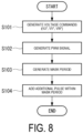
- FIG. 8 is a flowchart illustrating an example of a procedure for PWM signal generation processing according to the present embodiment.
- voltage commands vu*, vv*, and vw* are generated using the speed command for the motor 80 (S101).
- a PWM signal is generated on the basis of the voltage commands vu*, vv*, and vw* (S102).
- a mask period is generated for the generated PWM signal (S103).
- additional pulses AP are added during the mask period (S104).
- the mask period and the additional pulses AP during the mask period are generated, and the switching element group 21 is switched by this signal.
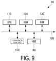
- FIG. 9 is a diagram illustrating an example of a hardware configuration of the control device 10 according to the present embodiment.
- the control device 10 is a computer system (calculator system) including, for example, a CPU 110, a read-only memory (ROM) 120 for storing programs or the like executed by the CPU 110, a random-access memory (ROM) 130 that functions as a work area when executing each program, a hard disk drive (HDD) 140 serving as a mass storage device, and a communication unit 150 for connecting to a network or the like.
- ROM read-only memory
- HDD hard disk drive
- a solid-state drive (SSD) may be used as the mass storage device.
- the control device 10 may also include an input unit consisting of a keyboard, a mouse, or the like, and a display unit consisting of a liquid crystal display device or the like for displaying data.
- the storage medium for storing programs or the like executed by the CPU 110 is not limited to the ROM 120.
- the storage medium may be another auxiliary storage device such as a magnetic disk, a magneto-optical disk, or a semiconductor memory.
- a series of processing steps to achieve the various functions described above are recorded in the hard disk drive 140 or the like in the form of a program, which is read by the CPU 110 into a RAM 130 or the like to process and compute the information.
- the program may be pre-installed in the ROM 120 or another storage media, stored and provided in a computer-readable storage medium, or delivered via wired or wireless communication means.
- the computer-readable storage medium includes a magnetic disk, a magneto-optical disk, a CD-ROM, a DVD-ROM, and a semiconductor memory.
- a mask period is provided for the PWM signal output from the PWM generation unit 22, and the additional pulse AP is added during the mask period.
- the voltage command input to the PWM generation unit 22 may be processed to output, from the PWM generation unit 22, a signal including a mask period and additional pulses AP.
- the processing of adding the additional pulse AP to the mask period can be performed either before or after the PWM signal is generated.
- the mask range is the angular range including the electrical angle at which the voltage becomes 0 (i.e., near the zero crossing).
- the PWM signal is generated on the basis of the voltage commands, and during the mask period, the additional pulse AP is generated in at least one of the former-stage period and the latter-stage period.
- required torque of the motor 80 during the mask period can be supplemented by the additional pulse AP, and the motor 80 can be smoothly driven.
- the additional pulse AP in the former-stage period
- motor torque at the timing of switching to the mask period can be supplemented
- the additional pulse AP in the latter-stage period motor torque at the timing of switching from the mask period can be supplemented. This is expected to reduce vibration, noise, and step-out.
- the value of the sum can be divided to generate multiple additional pulses AP such that the motor 80 smoothly rotates.
- An operation control system includes:
- the mask range is the angular range including the electrical angle at which the voltage becomes 0 (i.e., near the zero crossing).
- the PWM signal is generated on the basis of the voltage commands, and during the mask period, the additional pulse is generated in at least one of the former-stage period and the latter-stage period. This allows the switching loss to be reduced by setting the mask period, and allows the waveform distortion to be reduced during the mask period to suppress torque shock because additional pulse is generated in the former-stage period and/or the latter-stage period. That is, the torque for the motor required during the mask period can be supplemented by the additional pulse, and the motor can be smoothly driven.
- the command generation unit may be configured to generate the command in a manner to generate a PWM signal whose amplitude is made zero in the mask period on the basis of the voltage commands, and then generate the additional pulse in the mask period.
- the additional pulse can be efficiently generated during the mask period by generating the PWM signal whose amplitude is made zero during the mask period on the basis of the voltage commands and thereafter generating the additional pulse during the mask period.
- one or more of the additional pulses may be generated, and the sum of the pulse widths of the additional pulses may be greater than the pulse width of the PWM signal before or after the mask period.
- the operation control system by making the sum of the pulse widths of the additional pulses AP larger than the pulse width of the PWM signal before or after the mask period, the shortage of the motor torque during the mask period can be effectively compensated.
- the sum of the pulse widths of the additional pulses may be equal to the sum of the widths of the respective pulses of the PWM signals formed during the mask period on the basis of the voltage commands.
- the command generation unit may be configured to generate the command in a manner to divide the value of the sum to generate multiple additional pulses in the mask period.
- the motor when the sum of the pulse widths of the additional pulses AP exceeds a predetermined upper limit width (e.g., duty 100%), the motor can be smoothly rotated using the mask period as one carrier frequency by dividing the sum to generate multiple additional pulses.
- a predetermined upper limit width e.g., duty 100%
- An air conditioner according to the present disclosure includes:
- An operation control method includes:
- An operation control program is an operation control program for an operation control system including a pulse generation unit.
- the pulse generation unit is configured to generate a pulse signal for a switching element that drives an AC motor on the basis of a command.
- the operation control program is configured to cause a computer to execute:
Landscapes
- Engineering & Computer Science (AREA)
- Power Engineering (AREA)
- Inverter Devices (AREA)
- Air Conditioning Control Device (AREA)
- Control Of Ac Motors In General (AREA)
Abstract
Description
- The present disclosure relates to an operation control system and an air conditioner, an operation control method, and an operation control program.
- An air conditioner is primarily equipped with an inverter device that generates AC power for load (motor) drive to freely drive a motor of a compressor. An inverter device is well-known, which converts a three-phase AC voltage input from a commercial power supply (e.g., AC 200 V three-phase AC power supply) into a DC voltage once through a rectifier circuit (converter), and then converts the DC power into desired AC power for motor drive by the inverter device. As such inverter devices, those that perform output control by the v/f control method and those that perform output control by the vector control method are known.
- In
Patent Document 1, in order to reduce switching loss in the inverter device, a PWM-controlled pulse signal is stopped for a certain period (mask period) (partial two-phase current control). Partial two-phase current control is also disclosed in Patent Documents 2 and 3. -
- Patent Document 1:
JP 2018-164347 A - Patent Document 2:
JP 2019-4616 A - Patent Document 3:
JP 2019-4617 A - However, in performing partial two-phase current control, when a mask period is provided, control of the switching element suddenly stops and starts, which may distort the three-phase AC voltage waveform supplied to the motor and affect the motor's torque (whereby torque shock or the like occurs). In such a case, abnormal conditions such as vibration, noise or step-out may occur and stable operation of the motor may be degraded.
- In view of these circumstances, an object of the present disclosure is to provide an operation control system and an air conditioner, an operation control method, and an operation control program that can reduce loss and improve operation stability for motor.
- A first aspect of the present disclosure is an operation control system, which includes: a voltage command unit configured to generate sine wave voltage commands on the basis of a speed command for an AC motor; a command generation unit configured to, by using a predetermined angular range that includes an electrical angle at which the amplitude in the voltage commands is zero as a mask period, generate a command to: generate a pulse-width modulation (PWM) signal for the AC motor on the basis of the voltage commands during periods other than the mask period; and to generate, when the mask period is divided into a former-stage period and a latter-stage period, an additional pulse in at least one of the former-stage period and the latter-stage period; and a pulse generation unit configured to generate a pulse signal for a switching element that drives the AC motor on the basis of the command generated by the command generation unit.
- A second aspect of the present disclosure is an operation control method, which includes: generating sine wave voltage commands on the basis of a speed command for an AC motor; generating, by using a predetermined angular range that includes an electrical angle at which the amplitude in the voltage commands is zero as a mask period, a command to: generate a pulse-width modulation signal for the AC motor on the basis of the voltage commands during periods other than the mask period; and to generate, when the mask period is divided into a former-stage period and a latter-stage period, an additional pulse in at least one of the former-stage period and the latter-stage period; and generating a pulse signal for a switching element that drives the AC motor on the basis of the command generated by using said predetermined angular range as the mask period.
- A third aspect of the present disclosure is an operation control program configured to cause a computer to execute: a step of generating sine wave voltage commands on the basis of a speed command for an AC motor; a step of generating, by using a predetermined angular range that includes an electrical angle at which the amplitude in the voltage commands is zero as a mask period, a command to: generate a pulse-width modulation signal for the AC motor on the basis of the voltage commands during periods other than the mask period; to generate, when the mask period is divided into a former-stage period and a latter-stage period, an additional pulse in at least one of the former-stage period and the latter-stage period; and a step of generating a pulse signal for a switching element configured to drive the AC motor on the basis of the command generated by using the predetermined angular range as the mask period.
- According to the present disclosure, the effect of reducing loss and improving operation stability for a motor is achieved.
-
-
FIG. 1 is an overall view of an inverter device according to an embodiment of the present disclosure. -
FIG. 2 is a diagram illustrating a functional configuration of a control device according to an embodiment of the present disclosure. -
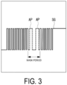
FIG. 3 is a diagram illustrating an example of a PWM signal according to an embodiment of the present disclosure. -
FIG. 4 is a diagram illustrating a waveform in a reference example. -
FIG. 5 is a diagram illustrating an example of generating an additional pulse in a case (1) according to an embodiment of the present disclosure. -
FIG. 6 is a diagram illustrating an example of generating an additional pulse in a case (2) according to an embodiment of the present disclosure. -
FIG. 7 is a diagram illustrating an example of generating an additional pulse in another case according to an embodiment of the present disclosure. -
FIG. 8 is a flow chart illustrating an example of a procedure for PWM signal generation processing according to an embodiment of the present disclosure. -
FIG. 9 is a diagram illustrating an example of a hardware configuration of a control device according to an embodiment of the present disclosure. - Hereinafter, an embodiment of an operation control system and an air conditioner, an operation control method, and an operation control program according to the present disclosure will be described with reference to the drawings.
-
FIG. 1 is a diagram illustrating a circuit configuration of an inverter device according to an embodiment. - An
inverter device 1 is installed in an outdoor unit of anair conditioner 90. Theinverter device 1 outputs, to a three-phase AC motor (motor 80) for driving the compressor of the above-described outdoor unit, an AC voltage (three-phase AC voltage) for load driving in accordance with a separately input speed command. Although a three-phase AC motor is illustrated and described in the present embodiment, a wide range of AC motors can be applied. Theinverter device 1 rotationally drives the three-phase AC motor (motor 80), that is, the load at a desired rotational speed on the basis of the AC voltage for load driving. - The
inverter device 1 includes acontrol device 10, an invertermain circuit 20, and a motorcurrent detecting unit 30. - The
inverter device 1 converts a DC voltage Vdc supplied by a DC power supply PS into a three-phase AC voltage consisting of a U-phase AC voltage, a V-phase AC voltage, and a W-phase AC voltage, which are AC voltages for load driving to rotationally drive themotor 80. - The motor current detecting
unit 30 is provided on each of the wiring lines for the three phases connected from theinverter device 1 to themotor 80. The motorcurrent detecting unit 30 detects currents iu, iv, and iw of the U-phase, the V-phase, and the W-phase flowing through themotor 80 in relation to the three-phase applied voltage (AC voltage vu, vv, vw) output from theinverter device 1 to themotor 80, respectively, and notifies thecontrol device 10 of the detection result of each current iu, iv, and iw. - The inverter
main circuit 20 includes aswitching element group 21, a positive electrode DC terminal Qa, and a negative electrode DC terminal Qb. - The positive electrode DC terminal Qa and the negative electrode DC terminal Qb are terminals to which the DC voltage Vdc is input.
- The positive electrode DC terminal Qa and the negative electrode DC terminal Qb are connected to the positive and negative electrodes of the DC power supply PS, respectively.
- The
switching element group 21 includes three pairs of two switching elements connected in series between the DC voltage Vdc. The switching element is, for example, a power transistor such as an Insulated Gate Bipolar Transistor (IGBT). Each pair of the above series-connected switching elements is provided corresponding to each of the three phases for rotationally driving the three-phase AC motor (motor 80). - As illustrated in
FIG. 1 , theswitching element group 21 includes a pair of an upperarm switching element 21 UH and a lower arm switching element 21UL connected in series, from the positive electrode DC terminal Qa to the negative electrode DC terminal Qb into which DC voltage Vdc is input. - Furthermore, the
switching element group 21 includes a pair of an upper arm switching element 21VH and a lower arm switching element 21VL connected in series from the positive electrode DC terminal Qa to the negative electrode DC terminal Qb. - Furthermore, the
switching element group 21 includes a pair of an upper arm switching element 21WH and a lower arm switching element 21WL connected in series from the positive electrode DC terminal Qa to the negative electrode DC terminal Qb. - The pair of the upper arm switching element 21UH and the lower arm switching element 21UL are switched by a gate signal from a PWM generation unit 22 (described later) to generate an AC voltage vu in a U-phase. The pair of the upper arm switching element 21UH and the lower arm switching element 21UL are alternately switched in a region excluding a peak voltage region RGP and a zero voltage region RGZ.
- Similarly, the pair of the upper arm switching element 21VH and the lower arm switching element 21VL are switched by the gate signal from the
PWM generation unit 22 to generate an AC voltage vv in a V-phase. The pair of the upper arm switching element 21VH and the lower arm switching element 21VL are alternately switched in the region excluding the peak voltage region RGP and the zero voltage region RGZ. - Similarly, the pair of the upper arm switching element 21WH and the lower arm switching element 21WL are switched by the gate signal from the
PWM generation unit 22 to generate an AC voltage vw in a W-phase. The pair of the upper arm switching element 21WH and the lower arm switching element 21WL are alternately switched in the region excluding the peak voltage region RGP and the zero voltage region RGZ. - The
PWM generation unit 22 generates a gate signal (PWM signal) to drive theswitching element group 21 and turn theswitching element group 21 on and off, in relation to a command (described later) received from a two-phase/three-phase conversion unit 13, which is provided in thecontrol device 10. - In the present embodiment, the
PWM generation unit 22 acquires AC voltage commands vu*, vv*, vw*. ThePWM generation unit 22 generates a PWM-controlled pulse signal (hereinafter also referred to as "PWM signal") with a duty rate proportional to the voltage of each waveform at each timing of the acquired AC voltage commands vu*, vv* and vw*. - Specifically, the
PWM generation unit 22 outputs a gate signal SG (21UH), a gate signal SG (21UL), a gate signal SG (21VH), a gate signal SG (21VL), a gate signal SG (21WH), and a gate signal SG (21WL) to the gates of the switching element 21UH, the switching element 21UL, the switching element 21VH, the switching element 21VL, the switching element 21WH, and the switching element 21WL, respectively, which will be described later. - The
PWM generation unit 22 generates the gate signal SG (21UH) and the gate signal SG (21UL) on the basis of the AC voltage command vu*. - Similarly, the
PWM generation unit 22 generates the gate signal SG (21VH) and the gate signal SG (21VL) on the basis of the AC voltage command vv*. - Similarly, the
PWM generation unit 22 generates the gate signal SG (21WH) and the gate signal SG (21WL) on the basis of the AC voltage command vw*. - The signals output from the
PWM generation unit 22 are corrected as described below at a maskperiod generation unit 61 and apulse addition unit 62, which will be described later. - As illustrated in
FIG. 2 , thecontrol device 10 is functionally provided with aspeed control unit 11, acurrent control unit 12, a two-phase/three-phase conversion unit 13, thePWM generation unit 22, and acommand generation unit 71. During periods other than the mask period, thecommand generation unit 71 generates a command to generate a PWM signal on the basis of the voltage commands and generates an additional pulse during the mask period. Thecommand generation unit 71 includes a maskperiod command unit 63 and a pulseaddition command unit 64. Note that, thePWM generation unit 22, the maskperiod generation unit 61, and thepulse addition unit 62 constitute apulse generation unit 72. - In the present embodiment, a computer system functions as the
control device 10 by executing a program described later. - The
speed control unit 11 outputs a speed command for rotating themotor 80 at a desired rotational speed ω. - The
current control unit 12 receives input of a speed command from thespeed control unit 11 and generates voltage commands on two axes (delta and gamma axes) of a rotating rectangular coordinate system on the basis of the current iu, iv, and iw detected at the motorcurrent detecting unit 30. For example, thecurrent control unit 12 generates and outputs a δ axis voltage command and a γ axis voltage command as voltage commands. - The two-phase/three-
phase conversion unit 13 performs coordinate conversion on the voltage command output from thecurrent control unit 12 to AC voltage commands vu*, vv*, and vw* corresponding to each of the AC voltages of the three phases. In this way, with thecurrent control unit 12 and the two-phase/three-phase conversion unit 13, a (similar) sine wave corresponding to each of the desired three-phase AC is output, and sine wave voltage commands are generated based on the speed command of the AC motor. - Thus, when the voltage command is acquired, a PWM signal is generated at the
PWM generation unit 22 by comparing the voltage command with the voltage waveform of a reference triangular wave (or saw-shaped wave). When the PWM signal is generated on the basis of a desired sine wave voltage command, it can be used without being limited to the above configuration. - Note that when the AC voltage commands vu*, vv*, and vw* are each sine waves and the
inverter device 1 performs PWM control with no change to the sine waves, switching loss in theswitching element group 21 may be large. Thus, it is preferable to perform two-arm type control. The two-arm type control is control of turning on each switching element for a predetermined period of time. Specifically, in a large region (peak voltage region RGP) of (the absolute value of) each phase voltage of the three-phase AC voltage, the upper arm switching elements 21UH, 21VH, 21WH, and the lower arm switching elements 21UL, 21VL, 21WL are turned on (continuously-on) over all the multi-period regions of the PWM period. - The
control device 10 includes the maskperiod command unit 63 in order to reduce switching losses. The mask period (zero voltage region RGZ) is a period when the duty cycle is 0% (continuously-off) and all regions in the period have an off-signal (no pulse). In other words, PWM signals are stopped during the mask period. The mask period is set as a predetermined angular range that includes an electrical angle at which the amplitude in the voltage commands (AC voltage commands vu*, vv*, vw*) is zero. The angular range is, for example, 60 degrees. The maskperiod command unit 63 corrects the PWM signal such that the mask period is formed in a preset angular range. Specifically, the maskperiod command unit 63 outputs a command to a maskperiod generation unit 61 to correct the PWM signal generated at thePWM generation unit 22. - The formation method of the mask period is not limited to the above method provided that the mask period can be formed.
- Multiple pulses during the mask period are removed by the mask
period command unit 63. This suppresses switching losses. For example, in the U-phase, the current iu is kept in a state of substantially not flowing in all regions during the mask period. On the other hand, because the other phases are deviated from each other, the current iv of the V-phase and the current iw of the W-phase flow even during the mask period of the U-phase. That is, since the currents in these two phases partially flow, control that stops the current of a specific phase using a mask period (while currents in the other two phases flow) is called partial two-phase current control. In other words, the partial two-phase current control is control of, when generating PWM signals on the basis of the voltage commands vu*, vv*, and vw*, stopping the pulse of any one phase during the mask period. - As described above, partial two-phase current control is possible. However, during the mask period, the PWM control suddenly stops and starts. In the mask period, since the PWM signal is stopped, motor torque may be insufficient and the waveform may be distorted. This can cause phenomena such as vibration, noise, or step-out.
- To deal with this, as illustrated in
FIG. 2 , thecontrol device 10 is provided with the pulseaddition command unit 64. That is, thecontrol device 10 and thePWM generation unit 22 constitute an operation control system that generates PWM signals for operation control. The pulseaddition command unit 64 outputs a command to thepulse addition unit 62 to correct the PWM signal corrected by the maskperiod generation unit 61. - For example, as illustrated in
FIG. 3 , a signal including an additional pulse AP generated during the mask period is output as a gate signal. Thus, during periods other than the mask period, PWM signals are generated on the basis of the voltage commands vu*, vv*, and vw*, and during the mask period, an additional pulse AP is generated not on the basis of the voltage commands vu*, vv*, and vw*. That is, the additional pulse AP is formed by the pulseaddition command unit 64 during the mask period in which pulses are not generally formed. No pulse other than the additional pulse AP is formed during the mask period. The number of the additional pulses AP formed during the mask period is smaller than the number of PWM pulses that would have been formed during the mask period on the basis of the voltage commands vu*, vv*, and vw*. - Next, a specific example of the additional pulse AP in the mask period is described.
- When the mask period is short, generated torque shock is considered to be small. Specifically, when the mask period is less than +/- 5 deg (i.e., less than 10 degs), the generated torque shock is minor and the additional pulse AP may be unnecessary. When the mask period is long, for example, +/- 20 deg (i.e., 40 deg ), the disturbance of the generated current waveform becomes large, which causes step-out and vibration.
- For this reason, the additional pulse AP is preferably generated during the mask period when the mask period is +/-5 deg or greater.
- During the mask period, when the mask period is divided into a former-stage period and a latter-stage period, the additional pulse AP is generated during at least one of the former-stage period and the latter-stage period. The former-stage period is a former-stage of the mask period, including a start point of the mask period, and the latter-stage period is a latter-stage of the mask period, including an end point of the mask period. The former-stage period and the latter-stage period may be separated by a predetermined timing (e.g., the center) in the mask period or by an intermediate period including the center period in the mask period. In the present embodiment, a case where the mask period is divided into a former-stage period and a latter-stage period with the center of the mask period as a boundary, will be described as an example.
- Providing the additional pulse AP in the former-stage period makes it possible to suppress the torque shock generated because of the stop of PWM control due to the start of the mask period. Providing the additional pulse AP in the latter-stage period makes it possible to suppress the torque shock generated because of the start of PWM control (start from stop) due to the end of the mask period.
- That is, there are two cases in which the additional pulse AP is generated. (1) The additional pulse AP is generated during the former-stage period and not generated during the latter-stage period. (2) The additional pulse AP is generated during the former-stage period and during the latter-stage period.
-
FIG. 4 illustrates a waveform without a mask period, as a reference example. InFIG. 4 , for example, the period of M1 corresponds to the mask period. -
FIG. 5 illustrates an example of the case (1). InFIG. 5 , the horizontal axis represents a phase θ and the vertical axis represents voltage.FIG. 5 illustrates a case where the additional pulse AP is generated during the mask period M1 in the reference example ofFIG. 4 . As illustrated inFIG. 5 , the additional pulse AP is generated during the former-stage period of the mask period and not generated during the latter-stage period. -
FIG. 6 illustrates an example of the case (2). InFIG. 6 , the horizontal axis represents the phase θ and the vertical axis represents voltage.FIG. 6 illustrates a case where the additional pulses AP are generated during the mask period of M1 in the reference example ofFIG. 4 . As illustrated inFIG. 6 , additional pulses AP are generated during both the former-stage period and the latter-stage period of the mask period, respectively. - Another case in which the additional pulse AP is not generated during the former-stage period and is generated during the latter-stage period may also occur.
FIG. 7 illustrates an example of this case. InFIG. 7 , the horizontal axis represents the phase θ and the vertical axis represents voltage.FIG. 7 illustrates a case where the additional pulse AP is generated during the mask period M1 in the reference example ofFIG. 4 . As illustrated inFIG. 7 , the additional pulse AP is not generated during the former-stage period of the mask period and is generated during the latter-stage period. From the viewpoint of vibration suppression, cases (1) and (2) are more preferable as generation cases of the additional pulse AP. - Note that when the additional pulse AP is generated during the former-stage period, the additional pulse AP is preferably generated in a manner to approach the start point of the mask period. For example, after the start of the mask period, generation processing is performed such that the additional pulse AP is generated at the initial pulse rise timing during the PWM cycle. When the additional pulse AP is generated during the latter-stage period, the additional pulse AP is preferably generated in a manner to approach the end point of the mask period. For example, before the end of the mask period, generation processing is performed such that the additional pulse AP is generated at the last pulse rise timing during the PWM cycle.
- Of the several cases described above, the case (2) is more preferable from the viewpoint of effectively reducing torque shock.
- During the mask period, one or more of the additional pulses AP may be generated.
FIGS. 5 and7 illustrate a case of generating one additional pulse AP during the mask period, andFIG. 6 illustrates a case of generating two additional pulses AP during the mask period. It is also possible to generate multiple additional pulses AP during the former-stage period or the latter-stage period. - The pulse width of the additional pulse AP generated during the mask period (the total pulse width when multiple additional pulses AP are generated) is set wider than the pulse width of the PWM signal before or after the mask period to compensate for torque during the mask period. Specifically, the pulse of the PWM signal before or after the mask period is the pulse of the PWM signal immediately before or after the mask period. As illustrated in
FIGS. 5 ,6 and7 , the sum of the additional pulse widths is greater than the pulse width of either a pulse P1 before the mask period or a pulse P2 after the mask period. - Specifically, the sum of the pulse widths of the additional pulses AP generated during the mask period is equal to the sum of the widths of the individual pulses of the PWM signals formed during the mask period on the basis of the voltage commands vu*, vv*, vw*. In other words, the pulses that would have been generated by PWM control during the mask period are aggregated and added as additional pulses AP. During the period M1 in
FIG. 4 , it is assumed that P pulses are generated. When the period M1 is assumed as the mask period, it is assumed that these P pulses are not generated. Thus, inFIGS. 5 ,6 and7 , the P pulses are aggregated and generated as additional pulses AP during the mask period. Because multiple pulses are aggregated, the sum of the pulse widths of the additional pulses AP is larger than the pulse width of the PWM signal before or after the mask period. - When the sum of the pulse widths of the additional pulses AP during the mask period exceeds a predetermined upper limit width, the value of the sum is preferably divided to generate multiple additional pulses AP during the mask period. In other words, when the sum of the pulse widths of the pulses that would have been generated by PWM control during the mask period is larger than the upper limit value, the pulse widths of the PWM pulses that would have been generated during the mask period are divided by multiple additional pulses AP. The upper limit value is, for example, a duty ratio of 100% at the carrier frequency (PWM carrier frequency, PWM cycle). This allows the torque to be corrected and a decrease in smoothness of the rotation of the
motor 80 to be suppressed. - For example, when five PWM pulses that would have been generated in the mask period are assumed to be five pulses with a duty ratio of 17%, 19%, 19%, 20%, and 20%, the sum would be 17 + 19 + 19 + 20 + 20 = 95%. Because this is a duty ratio of 100% or less, an additional pulse AP with a duty ratio of 95% is generated during the mask period.
- For example, when PWM pulses that would have been generated in the mask period are assumed to be seven pulses with a duty ratio of 17%, 19%, 19%, 20%, 20%, 21%, and 22%, the sum would be 17 + 19 + 19 + 20 + 20 + 21 + 22 = 137%. Because this total is greater than a duty ratio of 100%, one additional pulse AP with a duty ratio of 100% and one additional pulse AP with a duty ratio of 37% (two additional pulses AP in total) are generated during the mask period. Such division into multiple additional pulses AP is not limited to a case where one pulse has a duty ratio of 100%. Arbitrary division in which, for example, two additional pulses AP with a duty ratio of 68% and 69% are generated may also be employed.
- Next, an example of PWM signal generation processing by the
control device 10 will be described with reference toFIG. 8. FIG. 8 is a flowchart illustrating an example of a procedure for PWM signal generation processing according to the present embodiment. - First, voltage commands vu*, vv*, and vw* are generated using the speed command for the motor 80 (S101). Then, a PWM signal is generated on the basis of the voltage commands vu*, vv*, and vw* (S102). Next, a mask period is generated for the generated PWM signal (S103). Next, additional pulses AP are added during the mask period (S104). Thus, the mask period and the additional pulses AP during the mask period are generated, and the
switching element group 21 is switched by this signal. -
FIG. 9 is a diagram illustrating an example of a hardware configuration of thecontrol device 10 according to the present embodiment. - As illustrated in
FIG. 9 , thecontrol device 10 is a computer system (calculator system) including, for example, aCPU 110, a read-only memory (ROM) 120 for storing programs or the like executed by theCPU 110, a random-access memory (ROM) 130 that functions as a work area when executing each program, a hard disk drive (HDD) 140 serving as a mass storage device, and acommunication unit 150 for connecting to a network or the like. A solid-state drive (SSD) may be used as the mass storage device. These components are connected viabus 180. - The
control device 10 may also include an input unit consisting of a keyboard, a mouse, or the like, and a display unit consisting of a liquid crystal display device or the like for displaying data. - Note that the storage medium for storing programs or the like executed by the
CPU 110 is not limited to theROM 120. For example, the storage medium may be another auxiliary storage device such as a magnetic disk, a magneto-optical disk, or a semiconductor memory. - A series of processing steps to achieve the various functions described above are recorded in the
hard disk drive 140 or the like in the form of a program, which is read by theCPU 110 into aRAM 130 or the like to process and compute the information. As a result, the various functions described above are achieved. The program may be pre-installed in theROM 120 or another storage media, stored and provided in a computer-readable storage medium, or delivered via wired or wireless communication means. The computer-readable storage medium includes a magnetic disk, a magneto-optical disk, a CD-ROM, a DVD-ROM, and a semiconductor memory. - In the above example, a mask period is provided for the PWM signal output from the
PWM generation unit 22, and the additional pulse AP is added during the mask period. However, the voltage command input to thePWM generation unit 22 may be processed to output, from thePWM generation unit 22, a signal including a mask period and additional pulses AP. - Thus, the processing of adding the additional pulse AP to the mask period can be performed either before or after the PWM signal is generated.
- As described above, with the operation control system and the air conditioner, the operation control method, and the operation control program according to the present embodiment, in the voltage commands on the basis of the speed command for the
motor 80, the mask range is the angular range including the electrical angle at which the voltage becomes 0 (i.e., near the zero crossing). During periods other than the mask period, the PWM signal is generated on the basis of the voltage commands, and during the mask period, the additional pulse AP is generated in at least one of the former-stage period and the latter-stage period. With this configuration, switching losses can be reduced by setting the mask period, and the waveform distortion can be reduced during the mask period to suppress torque shock because the additional pulse AP is generated in the former-stage period and/or the latter-stage period. In other words, required torque of themotor 80 during the mask period can be supplemented by the additional pulse AP, and themotor 80 can be smoothly driven. For example, by generating the additional pulse AP in the former-stage period, motor torque at the timing of switching to the mask period can be supplemented, and by generating the additional pulse AP in the latter-stage period, motor torque at the timing of switching from the mask period can be supplemented. This is expected to reduce vibration, noise, and step-out. - Compared to a case of simply shortening the mask period, it is possible to ensure a period during which the switching is stopped while effectively compensating torque.
- By making the sum of the pulse widths of the additional pulses AP larger than the pulse width of the PWM signal before or after the mask period, a shortage of motor torque during the mask period can be effectively compensated.
- By making the sum of the pulse widths of the additional pulses AP equal to the sum of the widths of the individual pulses of the PWM signals formed during the mask period on the basis of the voltage commands, a shortage of motor torque during the mask period can be effectively compensated.
- When the sum of the pulse widths of the additional pulses AP exceeds a predetermined upper limit width (e.g., a duty rate of 100%), the value of the sum can be divided to generate multiple additional pulses AP such that the
motor 80 smoothly rotates. - The present disclosure is not limited to the above-described embodiment, and various modifications can be made within the scope of the gist of the invention.
- The operation control system and the air conditioner, the operation control method, and the operation control program described in each of the above-described embodiments are understood as follows, for example.
- An operation control system according to the present disclosure includes:
- a
voltage command unit AC motor 80; - a
command generation unit 71 configured to, by using a predetermined angular range that includes an electrical angle at which the amplitude in the voltage commands is zero as a mask period M1, generate a command to:- generate a PWM signal for the AC motor on the basis of the voltage commands during periods other than the mask period; and
- generate, when the mask period is divided into a former-stage period and a latter-stage period, an additional pulse AP in at least one of the former-stage period and the latter-stage period; and
- a
pulse generation unit 72 configured to generate a pulse signal for a switching element that drives the AC motor on the basis of the command.
- With the operation control system according to the present disclosure, in the voltage commands on the basis of the speed command for the AC motor, the mask range is the angular range including the electrical angle at which the voltage becomes 0 (i.e., near the zero crossing). During periods other than the mask period, the PWM signal is generated on the basis of the voltage commands, and during the mask period, the additional pulse is generated in at least one of the former-stage period and the latter-stage period. This allows the switching loss to be reduced by setting the mask period, and allows the waveform distortion to be reduced during the mask period to suppress torque shock because additional pulse is generated in the former-stage period and/or the latter-stage period. That is, the torque for the motor required during the mask period can be supplemented by the additional pulse, and the motor can be smoothly driven. For example, by generating the additional pulse in the former-stage period, motor torque at the timing of switching to the mask period can be supplemented, and by generating the additional pulse in the latter-stage period, motor torque at the timing of switching from the mask period can be supplemented. This is expected to reduce vibration, noise, and step-out.
- In the operation control system according to the present disclosure,
the command generation unit may be configured to generate the command in a manner to generate a PWM signal whose amplitude is made zero in the mask period on the basis of the voltage commands, and then generate the additional pulse in the mask period. - With the operation control system according to the present disclosure, the additional pulse can be efficiently generated during the mask period by generating the PWM signal whose amplitude is made zero during the mask period on the basis of the voltage commands and thereafter generating the additional pulse during the mask period.
- In the operation control system according to the present disclosure, during the mask period,
one or more of the additional pulses may be generated, and the sum of the pulse widths of the additional pulses may be greater than the pulse width of the PWM signal before or after the mask period. - With the operation control system according to the present disclosure, by making the sum of the pulse widths of the additional pulses AP larger than the pulse width of the PWM signal before or after the mask period, the shortage of the motor torque during the mask period can be effectively compensated.
- In the operation control system according to the present disclosure,
the sum of the pulse widths of the additional pulses may be equal to the sum of the widths of the respective pulses of the PWM signals formed during the mask period on the basis of the voltage commands. - With the operation control system according to the present disclosure, by making the sum of the pulse widths of the additional pulses equal to the sum of the widths of the respective pulses of the PWM signals formed during the mask period on the basis of the voltage commands, the shortage of motor torque during the mask period can be effectively compensated.
- In the operation control system according to the present disclosure,
when the sum of the pulse widths of the additional pulses in the mask period exceeds a predetermined upper limit width, the command generation unit may be configured to generate the command in a manner to divide the value of the sum to generate multiple additional pulses in the mask period. - With the operation control system according to the present disclosure, when the sum of the pulse widths of the additional pulses AP exceeds a predetermined upper limit width (e.g., duty 100%), the motor can be smoothly rotated using the mask period as one carrier frequency by dividing the sum to generate multiple additional pulses.
- An air conditioner according to the present disclosure includes:
- the operation control system described above;
- a plurality of switching elements configured to be driven on the basis of signals generated by the operation control system; and
- an AC motor configured to be driven via an AC voltage generated by the plurality of switching elements.
- An operation control method according to the present disclosure includes:
- generating sine wave voltage commands on the basis of a speed command for an AC motor;
- generating, by using a predetermined angular range that includes an electrical angle at which the amplitude in the voltage command is zero as a mask period, a command to:
- generate a PWM signal for the AC motor on the basis of the voltage commands during periods other than the mask period; and
- generate, when the mask period is divided into a former-stage period and a latter-stage period, an additional pulse in at least one of the former-stage period and the latter-stage period; and
- generating a pulse signal for a switching element that drives the AC motor on the basis of the command.
- An operation control program according to the present disclosure is an operation control program for an operation control system including a pulse generation unit.
- The pulse generation unit is configured to generate a pulse signal for a switching element that drives an AC motor on the basis of a command.
- The operation control program is configured to cause a computer to execute:
- a process of generating sine wave voltage commands on the basis of a speed command for the AC motor;
- a process of generating, by using a predetermined angular range that includes an electrical angle at which the amplitude in the voltage command is zero as a mask period, a command to:
- generate a PWM signal for the AC motor on the basis of the voltage commands during periods other than the mask period; and
- generate, when the mask period is divided into a former-stage period and a latter-stage period, an additional pulse in at least one of the former-stage period and the latter-stage period.
-
- 1 Inverter device
- 10 Control device
- 11 Speed control unit
- 12 Current control unit
- 13 Two-phase/three-phase conversion unit
- 20 Inverter main circuit
- 21 Switching element group
- 22 PWM generation unit
- 30 Motor current detecting unit
- 61 Mask period generation unit
- 62 Pulse addition unit
- 63 Mask period command unit
- 64 Pulse addition command unit
- 71 Command generation unit
- 72 Pulse generation unit
- 80 Motor
- 110 CPU
- 120 ROM
- 130 RAM
- 140 Hard disk drive
- 150 Communication unit
- 180 Bus
- AP Additional pulse
Claims (8)
- An operation control system comprising:a voltage command unit (12, 13) configured to generate sine wave voltage commands (vu*, vv*, vw*) on the basis of a speed command for an AC motor (80);a command generation unit (71) configured to, by using a predetermined angular range that includes an electrical angle at which the amplitude in the voltage commands (vu*, vv*, vw*) is zero as a mask period (M1), generate a command to:generate a pulse-width modulation signal for the AC motor (80) on the basis of the voltage commands (vu*, vv*, vw*) during periods other than the mask period (M1); andgenerate, when the mask period (M1) is divided into a former-stage period and a latter-stage period, an additional pulse (AP) in at least one of the former-stage period and the latter-stage period; anda pulse generation unit (72) configured to generate a pulse signal for a switching element that drives the AC motor (80) on the basis of the command generated by the command generation unit (71).
- The operation control system according to claim 1, wherein
the command generation unit (71) is configured to generate the command in a manner to generate a pulse-width modulation signal whose amplitude is made zero in the mask period on the basis of the voltage commands (vu*, vv*, vw*) and then to generate the additional pulse (AP) in the mask period (M1). - The operation control system according to claim 1 or 2, wherein
in the mask period (M1), one or more of the additional pulses (AP) are generated, and the sum of the pulse widths of the additional pulses (AP) is greater than the pulse width of the pulse-width modulation signal before or after the mask period (M1). - The operation control system according to claim 3, wherein
the sum of the pulse widths of the additional pulses (AP) is equal to the sum of the widths of individual pulses of the pulse-width modulation signals formed during the mask period (M1) on the basis of the voltage commands (vu*, vv*, vw*). - The operation control system according to claim 3 or 4, wherein
when the sum of the pulse widths of the additional pulses (AP) in the mask period (M1) exceeds a predetermined upper limit width, the command generation unit (71) is configured to generate the command in a manner to divide the value of the sum to generate multiple additional pulses (AP) in the mask period (M1). - An air conditioner comprising:an operation control system according to any one of claims 1 to 5;a plurality of switching elements (21) configured to be driven on the basis of signals generated by the operation control system; andan AC motor (80) configured to be driven via an AC voltage generated by the plurality of switching elements (21).
- An operation control method comprising:generating sine wave voltage commands (vu*, vv*, vw*) on the basis of a speed command for an AC motor (80);generating, by using a predetermined angular range that includes an electrical angle at which the amplitude in the voltage commands (vu*, vv*, vw*) is zero as a mask period (M1), a command to:generate a pulse-width modulation signal for the AC motor (80) on the basis of the voltage commands (vu*, vv*, vw*) during periods other than the mask period (M1); andgenerate, when the mask period (M1) is divided into a former-stage period and a latter-stage period, an additional pulse (AP) in at least one of the former-stage period and the latter-stage period; andgenerating a pulse signal for a switching element that drives the AC motor (80) on the basis of the command generated by using said predetermined angular range as the mask period (M1).
- An operation control program configured to cause a computer to execute:a step of generating sine wave voltage commands (vu*, vv*, vw*) on the basis of a speed command for an AC motor (80);a step of generating, by using a predetermined angular range that includes an electrical angle at which the amplitude in the voltage commands (vu*, vv*, vw*) is zero as a mask period (M1), a command:to generate a pulse-width modulation signal for the AC motor (80) on the basis of the voltage commands (vu*, vv*, vw*) during periods other than the mask period (M1);to generate, when the mask period (M1) is divided into a former-stage period and a latter-stage period, an additional pulse (AP) in at least one of the former-stage period and the latter-stage period; anda step of generating a pulse signal for a switching element configured to drive the AC motor (80) on the basis of the command generated by using the predetermined angular range as the mask period (M1).
Applications Claiming Priority (1)
| Application Number | Priority Date | Filing Date | Title |
|---|---|---|---|
| JP2022053761A JP7858360B2 (en) | 2022-03-29 | 2022-03-29 | Operation control system and air conditioner, operation control method, and operation control program |
Publications (1)
| Publication Number | Publication Date |
|---|---|
| EP4254779A1 true EP4254779A1 (en) | 2023-10-04 |
Family
ID=85122271
Family Applications (1)
| Application Number | Title | Priority Date | Filing Date |
|---|---|---|---|
| EP23153519.6A Pending EP4254779A1 (en) | 2022-03-29 | 2023-01-26 | Operation control system and air conditioner, operation control method, and operation control program |
Country Status (2)
| Country | Link |
|---|---|
| EP (1) | EP4254779A1 (en) |
| JP (1) | JP7858360B2 (en) |
Citations (4)
| Publication number | Priority date | Publication date | Assignee | Title |
|---|---|---|---|---|
| EP3379718A1 (en) * | 2017-03-24 | 2018-09-26 | Mitsubishi Heavy Industries Thermal Systems, Ltd. | Inverter apparatus, air conditioner, method of controlling inverter apparatus, and program |
| EP3382870A1 (en) * | 2017-03-31 | 2018-10-03 | Mitsubishi Heavy Industries Thermal Systems, Ltd. | Inverter apparatus, air conditioner, method of controlling inverter apparatus, and program |
| EP3416280A1 (en) * | 2017-06-15 | 2018-12-19 | Mitsubishi Heavy Industries Thermal Systems, Ltd. | Inverter apparatus, air conditioner, method of controlling inverter apparatus, and program |
| EP3416281A1 (en) * | 2017-06-15 | 2018-12-19 | Mitsubishi Heavy Industries Thermal Systems, Ltd. | Inverter apparatus, air conditioner, method of controlling inverter apparatus, and program |
-
2022
- 2022-03-29 JP JP2022053761A patent/JP7858360B2/en active Active
-
2023
- 2023-01-26 EP EP23153519.6A patent/EP4254779A1/en active Pending
Patent Citations (7)
| Publication number | Priority date | Publication date | Assignee | Title |
|---|---|---|---|---|
| EP3379718A1 (en) * | 2017-03-24 | 2018-09-26 | Mitsubishi Heavy Industries Thermal Systems, Ltd. | Inverter apparatus, air conditioner, method of controlling inverter apparatus, and program |
| JP2018164347A (en) | 2017-03-24 | 2018-10-18 | 三菱重工サーマルシステムズ株式会社 | INVERTER DEVICE, AIR CONDITIONER, INVERTER DEVICE CONTROL METHOD AND PROGRAM |
| EP3382870A1 (en) * | 2017-03-31 | 2018-10-03 | Mitsubishi Heavy Industries Thermal Systems, Ltd. | Inverter apparatus, air conditioner, method of controlling inverter apparatus, and program |
| EP3416280A1 (en) * | 2017-06-15 | 2018-12-19 | Mitsubishi Heavy Industries Thermal Systems, Ltd. | Inverter apparatus, air conditioner, method of controlling inverter apparatus, and program |
| EP3416281A1 (en) * | 2017-06-15 | 2018-12-19 | Mitsubishi Heavy Industries Thermal Systems, Ltd. | Inverter apparatus, air conditioner, method of controlling inverter apparatus, and program |
| JP2019004616A (en) | 2017-06-15 | 2019-01-10 | 三菱重工サーマルシステムズ株式会社 | Inverter device, air conditioner, control method for inverter device, and program |
| JP2019004617A (en) | 2017-06-15 | 2019-01-10 | 三菱重工サーマルシステムズ株式会社 | INVERTER DEVICE, AIR CONDITIONER, INVERTER DEVICE CONTROL METHOD AND PROGRAM |
Also Published As
| Publication number | Publication date |
|---|---|
| JP7858360B2 (en) | 2026-05-14 |
| JP2023146537A (en) | 2023-10-12 |
Similar Documents
| Publication | Publication Date | Title |
|---|---|---|
| US8878477B2 (en) | Electric motor driving apparatus having failure detection circuit, and failure detection method for the electric motor driving apparatus having failure detection circuit | |
| JP4306298B2 (en) | Motor control device | |
| JP2007143316A (en) | Motor control device | |
| KR20140053766A (en) | Vector controller and motor controller using the same, air-conditioner | |
| CN103222179B (en) | Power-converting device | |
| KR20120036246A (en) | Motor control system | |
| EP4254778A1 (en) | Operation control system and air conditioner, operation control method, and operation control program | |
| EP3379718A1 (en) | Inverter apparatus, air conditioner, method of controlling inverter apparatus, and program | |
| US11374505B2 (en) | Inverter device for performing a power conversion operation to convert DC power to AC power | |
| JP2017046528A (en) | Power control method and power control apparatus | |
| JP2006352957A (en) | Control device for synchronous motor | |
| JP7858360B2 (en) | Operation control system and air conditioner, operation control method, and operation control program | |
| JP6647448B2 (en) | Inverter control device and inverter control method | |
| JP3788346B2 (en) | Voltage type PWM inverter control device | |
| JP2022134404A (en) | Inverter controller | |
| US12362697B2 (en) | Rotating electrical machine control device | |
| JP7767934B2 (en) | Electric motor control method and electric motor control device | |
| JP2006166628A (en) | Power converter control method | |
| JP4126609B2 (en) | Two-phase modulation motor controller | |
| JP4513937B2 (en) | Correction method of voltage error due to dead band of PWM voltage source inverter and PWM voltage source inverter | |
| WO2024057368A1 (en) | Inverter control device | |
| JP2023141697A (en) | Motor compressor | |
| JP2017070073A (en) | Power control method and power control apparatus | |
| JP6458683B2 (en) | Power control method and power control apparatus | |
| JP2017073866A (en) | In-vehicle electric compressor |
Legal Events
| Date | Code | Title | Description |
|---|---|---|---|
| PUAI | Public reference made under article 153(3) epc to a published international application that has entered the european phase |
Free format text: ORIGINAL CODE: 0009012 |
|
| STAA | Information on the status of an ep patent application or granted ep patent |
Free format text: STATUS: THE APPLICATION HAS BEEN PUBLISHED |
|
| AK | Designated contracting states |
Kind code of ref document: A1 Designated state(s): AL AT BE BG CH CY CZ DE DK EE ES FI FR GB GR HR HU IE IS IT LI LT LU LV MC ME MK MT NL NO PL PT RO RS SE SI SK SM TR |
|
| STAA | Information on the status of an ep patent application or granted ep patent |
Free format text: STATUS: REQUEST FOR EXAMINATION WAS MADE |
|
| 17P | Request for examination filed |
Effective date: 20240328 |
|
| RBV | Designated contracting states (corrected) |
Designated state(s): AL AT BE BG CH CY CZ DE DK EE ES FI FR GB GR HR HU IE IS IT LI LT LU LV MC ME MK MT NL NO PL PT RO RS SE SI SK SM TR |
|
| GRAP | Despatch of communication of intention to grant a patent |
Free format text: ORIGINAL CODE: EPIDOSNIGR1 |
|
| STAA | Information on the status of an ep patent application or granted ep patent |
Free format text: STATUS: GRANT OF PATENT IS INTENDED |