EP4254758A1 - Direct current/direct current converter and control method thereof - Google Patents
Direct current/direct current converter and control method thereof Download PDFInfo
- Publication number
- EP4254758A1 EP4254758A1 EP21898291.6A EP21898291A EP4254758A1 EP 4254758 A1 EP4254758 A1 EP 4254758A1 EP 21898291 A EP21898291 A EP 21898291A EP 4254758 A1 EP4254758 A1 EP 4254758A1
- Authority
- EP
- European Patent Office
- Prior art keywords
- value
- voltage value
- reference voltage
- slope
- converter
- Prior art date
- Legal status (The legal status is an assumption and is not a legal conclusion. Google has not performed a legal analysis and makes no representation as to the accuracy of the status listed.)
- Pending
Links
Images




Classifications
-
- H—ELECTRICITY
- H02—GENERATION; CONVERSION OR DISTRIBUTION OF ELECTRIC POWER
- H02J—ELECTRIC POWER NETWORKS; CIRCUIT ARRANGEMENTS OR SYSTEMS FOR SUPPLYING OR DISTRIBUTING ELECTRIC POWER; SYSTEMS FOR STORING ELECTRIC ENERGY
- H02J3/00—Circuit arrangements for AC mains or AC distribution networks
- H02J3/28—Arrangements for balancing of the load in networks by storage of energy
- H02J3/32—Arrangements for balancing of the load in networks by storage of energy using batteries or super capacitors with converting means
-
- H—ELECTRICITY
- H02—GENERATION; CONVERSION OR DISTRIBUTION OF ELECTRIC POWER
- H02M—APPARATUS FOR CONVERSION BETWEEN AC AND AC, BETWEEN AC AND DC, OR BETWEEN DC AND DC, AND FOR USE WITH MAINS OR SIMILAR POWER SUPPLY SYSTEMS; CONVERSION OF DC OR AC INPUT POWER INTO SURGE OUTPUT POWER; CONTROL OR REGULATION THEREOF
- H02M1/00—Details of apparatus for conversion
- H02M1/0067—Converter structures employing plural converter units, other than for parallel operation of the units on a single load
- H02M1/007—Plural converter units in cascade
-
- H—ELECTRICITY
- H02—GENERATION; CONVERSION OR DISTRIBUTION OF ELECTRIC POWER
- H02J—ELECTRIC POWER NETWORKS; CIRCUIT ARRANGEMENTS OR SYSTEMS FOR SUPPLYING OR DISTRIBUTING ELECTRIC POWER; SYSTEMS FOR STORING ELECTRIC ENERGY
- H02J7/00—Circuit arrangements for charging or discharging batteries or for supplying loads from batteries
- H02J7/02—Circuit arrangements for charging or discharging batteries or for supplying loads from batteries for charging batteries from AC mains by converters
- H02J7/04—Regulation of charging current or voltage
- H02J7/06—Regulation of charging current or voltage using discharge tubes or semiconductor devices
-
- H—ELECTRICITY
- H02—GENERATION; CONVERSION OR DISTRIBUTION OF ELECTRIC POWER
- H02J—ELECTRIC POWER NETWORKS; CIRCUIT ARRANGEMENTS OR SYSTEMS FOR SUPPLYING OR DISTRIBUTING ELECTRIC POWER; SYSTEMS FOR STORING ELECTRIC ENERGY
- H02J7/00—Circuit arrangements for charging or discharging batteries or for supplying loads from batteries
- H02J7/90—Regulation of charging or discharging current or voltage
-
- H—ELECTRICITY
- H02—GENERATION; CONVERSION OR DISTRIBUTION OF ELECTRIC POWER
- H02J—ELECTRIC POWER NETWORKS; CIRCUIT ARRANGEMENTS OR SYSTEMS FOR SUPPLYING OR DISTRIBUTING ELECTRIC POWER; SYSTEMS FOR STORING ELECTRIC ENERGY
- H02J7/00—Circuit arrangements for charging or discharging batteries or for supplying loads from batteries
- H02J7/90—Regulation of charging or discharging current or voltage
- H02J7/927—Regulation of charging or discharging current or voltage with introduction of pulses during the charging process
-
- H—ELECTRICITY
- H02—GENERATION; CONVERSION OR DISTRIBUTION OF ELECTRIC POWER
- H02J—ELECTRIC POWER NETWORKS; CIRCUIT ARRANGEMENTS OR SYSTEMS FOR SUPPLYING OR DISTRIBUTING ELECTRIC POWER; SYSTEMS FOR STORING ELECTRIC ENERGY
- H02J7/00—Circuit arrangements for charging or discharging batteries or for supplying loads from batteries
- H02J7/90—Regulation of charging or discharging current or voltage
- H02J7/933—Regulation of charging or discharging current or voltage the cycle being controlled or terminated in response to electric parameters
-
- H—ELECTRICITY
- H02—GENERATION; CONVERSION OR DISTRIBUTION OF ELECTRIC POWER
- H02M—APPARATUS FOR CONVERSION BETWEEN AC AND AC, BETWEEN AC AND DC, OR BETWEEN DC AND DC, AND FOR USE WITH MAINS OR SIMILAR POWER SUPPLY SYSTEMS; CONVERSION OF DC OR AC INPUT POWER INTO SURGE OUTPUT POWER; CONTROL OR REGULATION THEREOF
- H02M1/00—Details of apparatus for conversion
- H02M1/0003—Details of control, feedback or regulation circuits
- H02M1/0006—Arrangements for supplying an adequate voltage to the control circuit of converters
-
- H—ELECTRICITY
- H02—GENERATION; CONVERSION OR DISTRIBUTION OF ELECTRIC POWER
- H02M—APPARATUS FOR CONVERSION BETWEEN AC AND AC, BETWEEN AC AND DC, OR BETWEEN DC AND DC, AND FOR USE WITH MAINS OR SIMILAR POWER SUPPLY SYSTEMS; CONVERSION OF DC OR AC INPUT POWER INTO SURGE OUTPUT POWER; CONTROL OR REGULATION THEREOF
- H02M1/00—Details of apparatus for conversion
- H02M1/0003—Details of control, feedback or regulation circuits
- H02M1/0025—Arrangements for modifying reference values, feedback values or error values in the control loop of a converter
-
- H—ELECTRICITY
- H02—GENERATION; CONVERSION OR DISTRIBUTION OF ELECTRIC POWER
- H02M—APPARATUS FOR CONVERSION BETWEEN AC AND AC, BETWEEN AC AND DC, OR BETWEEN DC AND DC, AND FOR USE WITH MAINS OR SIMILAR POWER SUPPLY SYSTEMS; CONVERSION OF DC OR AC INPUT POWER INTO SURGE OUTPUT POWER; CONTROL OR REGULATION THEREOF
- H02M1/00—Details of apparatus for conversion
- H02M1/14—Arrangements for reducing ripples from DC input or output
-
- H—ELECTRICITY
- H02—GENERATION; CONVERSION OR DISTRIBUTION OF ELECTRIC POWER
- H02M—APPARATUS FOR CONVERSION BETWEEN AC AND AC, BETWEEN AC AND DC, OR BETWEEN DC AND DC, AND FOR USE WITH MAINS OR SIMILAR POWER SUPPLY SYSTEMS; CONVERSION OF DC OR AC INPUT POWER INTO SURGE OUTPUT POWER; CONTROL OR REGULATION THEREOF
- H02M1/00—Details of apparatus for conversion
- H02M1/32—Means for protecting converters other than automatic disconnection
-
- H—ELECTRICITY
- H02—GENERATION; CONVERSION OR DISTRIBUTION OF ELECTRIC POWER
- H02M—APPARATUS FOR CONVERSION BETWEEN AC AND AC, BETWEEN AC AND DC, OR BETWEEN DC AND DC, AND FOR USE WITH MAINS OR SIMILAR POWER SUPPLY SYSTEMS; CONVERSION OF DC OR AC INPUT POWER INTO SURGE OUTPUT POWER; CONTROL OR REGULATION THEREOF
- H02M3/00—Conversion of DC power input into DC power output
- H02M3/02—Conversion of DC power input into DC power output without intermediate conversion into AC
- H02M3/04—Conversion of DC power input into DC power output without intermediate conversion into AC by static converters
-
- H—ELECTRICITY
- H02—GENERATION; CONVERSION OR DISTRIBUTION OF ELECTRIC POWER
- H02M—APPARATUS FOR CONVERSION BETWEEN AC AND AC, BETWEEN AC AND DC, OR BETWEEN DC AND DC, AND FOR USE WITH MAINS OR SIMILAR POWER SUPPLY SYSTEMS; CONVERSION OF DC OR AC INPUT POWER INTO SURGE OUTPUT POWER; CONTROL OR REGULATION THEREOF
- H02M3/00—Conversion of DC power input into DC power output
- H02M3/02—Conversion of DC power input into DC power output without intermediate conversion into AC
- H02M3/04—Conversion of DC power input into DC power output without intermediate conversion into AC by static converters
- H02M3/10—Conversion of DC power input into DC power output without intermediate conversion into AC by static converters using discharge tubes with control electrode or semiconductor devices with control electrode
- H02M3/145—Conversion of DC power input into DC power output without intermediate conversion into AC by static converters using discharge tubes with control electrode or semiconductor devices with control electrode using devices of a triode or transistor type requiring continuous application of a control signal
- H02M3/155—Conversion of DC power input into DC power output without intermediate conversion into AC by static converters using discharge tubes with control electrode or semiconductor devices with control electrode using devices of a triode or transistor type requiring continuous application of a control signal using semiconductor devices only
- H02M3/156—Conversion of DC power input into DC power output without intermediate conversion into AC by static converters using discharge tubes with control electrode or semiconductor devices with control electrode using devices of a triode or transistor type requiring continuous application of a control signal using semiconductor devices only with automatic control of output voltage or current, e.g. switching regulators
- H02M3/158—Conversion of DC power input into DC power output without intermediate conversion into AC by static converters using discharge tubes with control electrode or semiconductor devices with control electrode using devices of a triode or transistor type requiring continuous application of a control signal using semiconductor devices only with automatic control of output voltage or current, e.g. switching regulators including plural semiconductor devices as final control devices for a single load
- H02M3/1582—Buck-boost converters
-
- H—ELECTRICITY
- H02—GENERATION; CONVERSION OR DISTRIBUTION OF ELECTRIC POWER
- H02J—ELECTRIC POWER NETWORKS; CIRCUIT ARRANGEMENTS OR SYSTEMS FOR SUPPLYING OR DISTRIBUTING ELECTRIC POWER; SYSTEMS FOR STORING ELECTRIC ENERGY
- H02J2207/00—Details of circuit arrangements for charging or discharging batteries or supplying loads from batteries
- H02J2207/10—Control circuit supply, e.g. means for supplying power to the control circuit
-
- H—ELECTRICITY
- H02—GENERATION; CONVERSION OR DISTRIBUTION OF ELECTRIC POWER
- H02J—ELECTRIC POWER NETWORKS; CIRCUIT ARRANGEMENTS OR SYSTEMS FOR SUPPLYING OR DISTRIBUTING ELECTRIC POWER; SYSTEMS FOR STORING ELECTRIC ENERGY
- H02J2207/00—Details of circuit arrangements for charging or discharging batteries or supplying loads from batteries
- H02J2207/20—Charging or discharging characterised by the power electronics converter
-
- H—ELECTRICITY
- H02—GENERATION; CONVERSION OR DISTRIBUTION OF ELECTRIC POWER
- H02J—ELECTRIC POWER NETWORKS; CIRCUIT ARRANGEMENTS OR SYSTEMS FOR SUPPLYING OR DISTRIBUTING ELECTRIC POWER; SYSTEMS FOR STORING ELECTRIC ENERGY
- H02J7/00—Circuit arrangements for charging or discharging batteries or for supplying loads from batteries
- H02J7/90—Regulation of charging or discharging current or voltage
- H02J7/94—Regulation of charging or discharging current or voltage in response to battery current
- H02J7/947—Regulation of charging or discharging current or voltage in response to battery current in response to integrated charge or discharge current
-
- H—ELECTRICITY
- H02—GENERATION; CONVERSION OR DISTRIBUTION OF ELECTRIC POWER
- H02M—APPARATUS FOR CONVERSION BETWEEN AC AND AC, BETWEEN AC AND DC, OR BETWEEN DC AND DC, AND FOR USE WITH MAINS OR SIMILAR POWER SUPPLY SYSTEMS; CONVERSION OF DC OR AC INPUT POWER INTO SURGE OUTPUT POWER; CONTROL OR REGULATION THEREOF
- H02M1/00—Details of apparatus for conversion
- H02M1/36—Means for starting or stopping converters
-
- H—ELECTRICITY
- H02—GENERATION; CONVERSION OR DISTRIBUTION OF ELECTRIC POWER
- H02M—APPARATUS FOR CONVERSION BETWEEN AC AND AC, BETWEEN AC AND DC, OR BETWEEN DC AND DC, AND FOR USE WITH MAINS OR SIMILAR POWER SUPPLY SYSTEMS; CONVERSION OF DC OR AC INPUT POWER INTO SURGE OUTPUT POWER; CONTROL OR REGULATION THEREOF
- H02M3/00—Conversion of DC power input into DC power output
- H02M3/22—Conversion of DC power input into DC power output with intermediate conversion into AC
- H02M3/24—Conversion of DC power input into DC power output with intermediate conversion into AC by static converters
- H02M3/28—Conversion of DC power input into DC power output with intermediate conversion into AC by static converters using discharge tubes with control electrode or semiconductor devices with control electrode to produce the intermediate AC
- H02M3/325—Conversion of DC power input into DC power output with intermediate conversion into AC by static converters using discharge tubes with control electrode or semiconductor devices with control electrode to produce the intermediate AC using devices of a triode or a transistor type requiring continuous application of a control signal
- H02M3/335—Conversion of DC power input into DC power output with intermediate conversion into AC by static converters using discharge tubes with control electrode or semiconductor devices with control electrode to produce the intermediate AC using devices of a triode or a transistor type requiring continuous application of a control signal using semiconductor devices only
- H02M3/33569—Conversion of DC power input into DC power output with intermediate conversion into AC by static converters using discharge tubes with control electrode or semiconductor devices with control electrode to produce the intermediate AC using devices of a triode or a transistor type requiring continuous application of a control signal using semiconductor devices only having several active switching elements
- H02M3/33576—Conversion of DC power input into DC power output with intermediate conversion into AC by static converters using discharge tubes with control electrode or semiconductor devices with control electrode to produce the intermediate AC using devices of a triode or a transistor type requiring continuous application of a control signal using semiconductor devices only having several active switching elements having at least one active switching element at the secondary side of an isolation transformer
- H02M3/33584—Bidirectional converters
-
- H—ELECTRICITY
- H02—GENERATION; CONVERSION OR DISTRIBUTION OF ELECTRIC POWER
- H02M—APPARATUS FOR CONVERSION BETWEEN AC AND AC, BETWEEN AC AND DC, OR BETWEEN DC AND DC, AND FOR USE WITH MAINS OR SIMILAR POWER SUPPLY SYSTEMS; CONVERSION OF DC OR AC INPUT POWER INTO SURGE OUTPUT POWER; CONTROL OR REGULATION THEREOF
- H02M7/00—Conversion of AC power input into DC power output; Conversion of DC power input into AC power output
- H02M7/42—Conversion of DC power input into AC power output without possibility of reversal
- H02M7/44—Conversion of DC power input into AC power output without possibility of reversal by static converters
- H02M7/48—Conversion of DC power input into AC power output without possibility of reversal by static converters using discharge tubes with control electrode or semiconductor devices with control electrode
Definitions
- the calculating of the right slope may include calculating the right slope of the droop control curve in which the reference voltage value and the required power value are operation points according to Equation 1 below.
- Slop e 1 P H , Limit ⁇ P set V H , Limit ⁇ V ref
- a delay according to a physical voltage fluctuation during a mode change can be removed.
- the power generation apparatus 10 is not limited thereto, and may be configured as a tidal power generation system in addition to the photovoltaic power generation system and the wind power generation system.
- the power generation apparatus 10 is not limited to the above-mentioned types, and may include all power generation systems which generate electric energy using new renewable energy such as solar heat, geothermal heat, or the like.
- FIG. 2 is a view for describing the energy storage system according to the embodiment.
- FIG. 3 is a view for describing the DC/DC converter according to the embodiment.
- the DC/DC converter 100 sets the new operation point when receiving the required power value and the reference voltage value from the inverter, and the operation mode determination unit 132 sets the operation mode according to the newly set operation point.
- the slope calculation unit 133 may calculate the left slope of the droop control curve in which the reference voltage value is an operation point according to Equation 2 below.
- Slop e 2 P set ⁇ P L , Limit V ref ⁇ V L , Limit
- the output power value calculation unit 134 may calculate the output power value by substituting a difference value between the link voltage value and the reference voltage value into the slope.
- the output power value calculation unit 134 may perform duty value compensation using a target current generation value and a feedback current.
- the output power value calculation unit 134 may calculate an output power value by multiplying a difference value acquired by subtracting the reference voltage value from the link voltage value by the left slope of the droop control curve in the discharging mode.
- the output power value calculation unit 134 may calculate an output power value by multiplying a difference value acquired by subtracting the link voltage value from the reference voltage value by the right slope of the droop control curve in the charging mode.
- control unit may calculate the output power value by calculating a difference value between a reference voltage value of 425 [V] and a link voltage value of 425 [V] which are setting values, and substituting the calculated difference value into the previously calculated slope and adding up the calculated difference value and the required power value.
- the control unit may calculate the output power value by substituting the difference value into the left slope in the discharging mode, and may calculate the output power value by substituting the difference value into the right slope in the charging mode.
- the control unit may calculate an output power value of -4500 [W] by adding up a value of 0 [W], acquired by substituting the difference value into the calculated slope, and a required power value of -4500 [W].
- FIG. 10 shows a voltage-power plane for describing an operation area of the control unit according to the embodiment.
- the DC/DC converter according to the embodiment may change the operation point of the DC/DC converter by receiving the required power value from the inverter to newly calculate the slope of the droop control curve, and calculating a current output to the battery according to the droop control curve to which the newly calculated slope is reflected. Further, a quick response is possible without a physical voltage fluctuation, and it is possible to perform driving of charging, discharging, and idle sections in all operation sections.
- FIG. 11 is an operational flow chart of an operation of a DC/DC converter control method according to the embodiment.
- an input unit may receive a required power value from an inverter (S1101).
- the input unit may receive a link voltage value from a direct current link capacitor (S1105).
Landscapes
- Engineering & Computer Science (AREA)
- Power Engineering (AREA)
- Dc-Dc Converters (AREA)
- Charge And Discharge Circuits For Batteries Or The Like (AREA)
Abstract
Description
- One embodiment of the present invention relates to a direct current/direct current (DC/DC) converter and a control method thereof.
- Electric energy is easily converted and transmitted, and thus is widely used. In order to efficiently use this electric energy, an energy storage system (ESS) is used. The energy storage system receives power and charges the power in a battery. Further, when power is required, the energy storage system supplies the power by discharging the power charged in the battery. Accordingly, the energy storage system can flexibly supply power.
- Specifically, a power supply system operates as follows when including the energy storage system. The energy storage system discharges electric energy stored in the battery when a load or system is in an overload. Further, when the load or system is in a light load, the energy storage system receives power from a power generation apparatus or system and charges the power in the battery.
- In addition, when the energy storage system is present independently of the power supply system, the energy storage system receives idle power from an external power source and charges the idle power in the battery. In addition, when a system or load is in an overload, the energy storage system supplies the power by discharging the power charged in the battery.
- This energy storage system performs droop control to improve stability during a charging operation or a discharging operation of the battery. Specifically, the energy storage system performs the droop control according to a charging state (SOC) of the battery. However, a conventional droop control method has a disadvantage that a charging and discharging voltage and a droop curve are fixed and thus an operation point of a DC/DC converter is changed only along the determined droop curve. Further, since power output is fixed at 0 in an idle section, there is a problem in that a non-response section is formed when the voltage falls or rises. In addition, there are problems in that discharging and idle driving cannot be performed when a link voltage is located in a charging voltage section, charging and the idle driving cannot be performed when the link voltage is located in a discharging voltage section, and the charging and discharging cannot be performed in the idle section.
- The present invention is directed to providing a direct current/direct current (DC/DC) converter capable of actively changing a droop control curve and an operation point, and a control method thereof.
- Further, the present invention is directed to providing a DC/DC converter matched with inverters of various manufacturers of which operation areas are different, and thus having improved compatibility and control safety, and a control method thereof.
- According to an embodiment, a direct current/direct current (DC/DC) converter control method includes: receiving a required power value from an inverter; receiving a reference voltage value from the inverter; calculating a slope of a droop control curve according to the reference voltage value and the required power value; receiving a link voltage value from a direct current link capacitor; substituting a difference value between the link voltage value and the reference voltage value into the slope to calculate an output power value; and calculating a target current value according to the output power value.
- The calculating of the slope of the droop control curve may include: calculating a right slope based on the reference voltage value; and calculating a left slope based on the reference voltage value.
- The calculating of the right slope may include calculating the right slope of the droop control curve in which the reference voltage value and the required power value are operation points according to
Equation 1 below.
- In
Equation 1, Slope1 is the right slope of the droop control curve based on the reference voltage value, PH,Limit is a maximally charged power value, VH,Limit is a starting voltage value of maximally charged power, Pset is the required power value received from the inverter, and Vref is the reference voltage value received from the inverter. - The calculating of the left slope may include calculating the left slope of the droop control curve in which the reference voltage value and the required power value are operation points according to
Equation 2 below.
- In
Equation 2, Slope2 is the left slope of the droop control curve based on the reference voltage value, PL,Limit is a maximally discharged power value, VL,Limit is a starting voltage value of maximally discharged power, Pset is the required power value received from the inverter, and Vref is the reference voltage value received from the inverter. - The DC/DC converter control method may further include outputting the target current value to the battery.
- According to an embodiment, a direct current/direct current (DC/DC) converter includes: an input unit configured to receive a required power value and a reference voltage value from an inverter and receive a link voltage value from a direct current link capacitor; and a control unit configured to calculate a slope of a droop control curve according to the reference voltage value and the required power value, substitute a difference value between the link voltage value and the reference voltage value into the slope to calculate an output power value, and calculate a target current value according to the output power value.
- According to a DC/DC converter of the present invention and a control method thereof, it is possible to change an operation point of the DC/DC converter.
- Further, a delay according to a physical voltage fluctuation during a mode change can be removed.
- In addition, charging, discharging, and idle driving are possible in all sections of an operation voltage.
- In addition, response stability according to the voltage fluctuation can be improved in all sections of the operation voltage.
-
-
FIG. 1 is a view for describing a schematic configuration of a power supply system according to an embodiment. -
FIG. 2 is a view for describing an energy storage system according to the embodiment. -
FIG. 3 is a view for describing a direct current/direct current (DC/DC) converter according to the embodiment. -
FIG. 4 is a control system block diagram according to the embodiment. -
FIG. 5 is a view for describing a control unit according to the embodiment. -
FIG. 6 is a view for describing a droop control curve of the energy storage system according to the embodiment. -
FIG. 7 shows a voltage-power plane for describing an operation area of the control unit according to the embodiment. -
FIG. 8 shows a voltage-power plane for describing an operation area of the control unit according to the embodiment. -
FIG. 9 shows a voltage-power plane for describing an operation area of the control unit according to the embodiment. -
FIG. 10 shows a voltage-power plane for describing an operation area of the control unit according to the embodiment. -
FIG. 11 is an operational flow chart of a DC/DC converter control method according to the embodiment. -
FIG. 12 is a view for describing an advantage of expanding the operation area related to proposed droop control compared to conventional droop control. - Hereinafter, preferable embodiments of the present invention will be described in detail with reference to the accompanying drawings.
- However, the technical spirit of the present invention is not limited to some embodiments which will be described and may be embodied in various forms, and one or more elements in the embodiments may be selectively combined and replaced to be used within the scope of the technical spirit of the present invention.
- Further, terms used in the embodiments of the present invention (including technical and scientific terms), may be interpreted with meanings that are generally understood by those skilled in the art unless particularly defined and described, and terms which are generally used, such as terms defined in a dictionary, may be understood in consideration of their contextual meanings in the related art.
- In addition, terms used in the description are provided not to limit the present invention but to describe the embodiments.
- In the specification, the singular form may also include the plural form unless the context clearly indicates otherwise and may include one or more of all possible combinations of A, B, and C when disclosed as at least one (or one or more) of "A, B, and C."
- In addition, terms such as first, second, A, B, (a), (b), and the like may be used to describe elements of the embodiments of the present invention.
- These terms are only provided to distinguish the elements from other elements, and the essence, sequence, order, or the like of the elements are not limited by the terms.
- Further, when particular elements are disclosed as being "connected," "coupled," or "linked" to other elements, the elements may include not only a case of being directly connected, coupled, or linked to other elements but also a case of being connected, coupled, or linked to other elements by elements between the elements and other elements.
- In addition, when one element is disclosed as being formed "on or under" another element, the term "on or under" includes both a case in which the two elements are in direct contact with each other and a case in which at least another element is disposed between the two elements (indirect contact). Further, when the term "on or under" is expressed, a meaning of not only an upward direction but also a downward direction may be included based on one element.
- Hereinafter, embodiments will be described in detail with reference to the accompanying drawings, and the same reference numerals are granted to the same or corresponding components regardless of the drawing numerals and overlapping descriptions thereof will be omitted
-
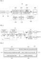
FIG. 1 is a view for describing a schematic configuration of a power supply system according to an embodiment. Referring toFIG. 1 , apower supply system 1 according to the embodiment includes apower generation apparatus 10, anenergy storage system 20, aninverter 30, an alternating current (AC)filter 40, an alternating current/alternating current (AC/AC)converter 50, asystem 60, asystem control unit 80, and aload 70. - The
power generation apparatus 10 may produce electric energy. When thepower generation apparatus 10 is a photovoltaic power generation system, thepower generation apparatus 10 may be a solar cell array. The solar cell array is a combination of a plurality of solar cell modules. The solar cell module may be a device which converts solar energy to electric energy to generate predetermined voltage and current by connecting a plurality of solar cells in series or parallel. Accordingly, the solar cell array may absorb solar energy and convert the solar energy to the electric energy. - Further, when the
power generation apparatus 10 is a wind power generation system, thepower generation apparatus 10 may be a fan which converts wind energy to electric energy. - Meanwhile, the
power generation apparatus 10 is not limited thereto, and may be configured as a tidal power generation system in addition to the photovoltaic power generation system and the wind power generation system. However, this is only an example, and thepower generation apparatus 10 is not limited to the above-mentioned types, and may include all power generation systems which generate electric energy using new renewable energy such as solar heat, geothermal heat, or the like. - Further, the
power supply system 1 may supply power only through theenergy storage system 20 without thepower generation apparatus 10. - In this case, the
power supply system 1 may not include thepower generation apparatus 10. - The
inverter 30 may convert direct current (DC) power to AC power. More specifically, the DC power supplied by thepower generation apparatus 10 or the DC power discharged by theenergy storage system 20 may be converted to the AC power. - The
AC filter 40 may filter a noise of the power converted to the AC power. Further, theAC filter 40 may be omitted according to the embodiment. - The AC/
AC converter 50 may convert a magnitude of a voltage of the noisefiltered AC power so that the AC power may be supplied to thesystem 60 or theload 70, and may supply the converted AC power to thesystem 60 or theload 70. Further, the AC/AC converter 50 may be omitted according to the embodiment. - The
system 60 is a system in which many power plants, substations, transmission and distribution lines, and loads are integrated and thus generation and use of electric power are performed. - The
load 70 may receive electric energy from a power generation system such as thepower generation apparatus 10 or the like or theenergy storage system 20 to consume power. - The energy storage system (ESS) 20 may be charged by receiving electric energy from the
power generation apparatus 10, and may discharge the charged electric energy according to a power supply and demand condition of thesystem 60 or theload 70. More specifically, when thesystem 60 or theload 70 is in a light load, theenergy storage system 20 may receive idle power from thepower generation apparatus 10 to perform charging. When thesystem 60 or theload 70 is in an overload, theenergy storage system 20 may discharge the charged power to supply the power to thesystem 60 or theload 70. Further, theenergy storage system 20 may be connected between thepower generation apparatus 10 and theinverter 30 to be electrically connected to thepower generation apparatus 10 and electrically connected to theinverter 30. - The
system control unit 80 may control operations of theenergy storage system 20, theinverter 30, and the AC/AC converter 50. More specifically, thesystem control unit 80 may control charging and discharging of theenergy storage system 20. When thesystem 60 or theload 70 is in an overload, thesystem control unit 80 may control theenergy storage system 20 to supply power and transfer the power to thesystem 60 or theload 70. When thesystem 60 or theload 70 is in a light load, thesystem control unit 80 may control an external power source or thepower generation apparatus 10 to supply power and transmit the power to theenergy storage system 20. -
FIG. 2 is a view for describing the energy storage system according to the embodiment. - Referring to
FIG. 2 , theenergy storage system 20 according to the embodiment may include a direct current/direct current (DC/DC)converter 100, abattery 200, and a chargingcontrol unit 300. Theenergy storage system 20 may be connected to theinverter 30 through a directcurrent link capacitor 90. That is, the directcurrent link capacitor 90 may be disposed between theenergy storage system 20 and theinverter 30. Accordingly, theenergy storage system 20 may receive a DC voltage Vdc of the directcurrent link capacitor 90 in a charging mode, and provide the DC voltage Vdc to the directcurrent link capacitor 90 in a discharging mode. - The
battery 200 may receive charging power from the DC/DC converter 100 in the charging mode, and perform a charging operation using the received power. Further, thebattery 200 may output previously stored power to the DC/DC converter 100 in the discharge mode. In addition, thebattery 200 may include a plurality of battery cells to perform charging and discharging operations. - The charging
control unit 300 may include a battery management system (BMS). The chargingcontrol unit 300 may provide battery state information on a state of thebattery 200 to thesystem control unit 80. For example, the chargingcontrol unit 300 may monitor at least one or more of a voltage, a current, a temperature, a remaining power amount, and a charging state of thebattery 200, and transmit the monitored state information of thebattery 200 to thesystem control unit 80. Further, the chargingcontrol unit 300 may make the plurality of battery cells maintain an appropriate voltage while being charged or discharged. In addition, the chargingcontrol unit 300 may operate based on a control signal from thesystem control unit 80. In addition, the chargingcontrol unit 300 may control the DC/DC converter 100 according to the monitored state information of thebattery 200. In addition, the chargingcontrol unit 300 may control the DC/DC converter 100 according to the charging mode or the discharging mode. More specifically, the chargingcontrol unit 300 may provide a charging control signal or a discharging control signal for controlling the DC/DC converter 100 to a converter control unit of the DC/DC converter 100, and the converter control unit of the DC/DC converter 100 may provide a pulse width modulation (PWM) signal to a switch of the DC/DC converter 100 based on the charging control signal or the discharging control signal. Further, the chargingcontrol unit 300 may control the DC/DC converter 100 to initially charge the directcurrent link capacitor 90 in the discharge mode of thebattery 200. That is, the chargingcontrol unit 300 may provide an initial charging control signal for controlling the DC/DC converter 100 to the converter control unit of the DC/DC converter 100, and the converter control unit of the DC/DC converter 100 may provide an initial charging switch signal to the switch of the DC/DC converter 100 based on the initial charging control signal. Further, the chargingcontrol unit 300 may control the DC/DC converter 100 to improve power conversion efficiency of the DC/DC converter 100. More specifically, the chargingcontrol unit 300 may provide a power conversion efficiency control signal capable of improving the power conversion efficiency of the DC/DC converter 100 to the converter control unit of the DC/DC converter 100, and the converter control unit of the DC/DC converter 100 may provide the PWM signal to the switch of the DC/DC converter 100 based on the power conversion efficiency control signal. - The DC/
DC converter 100 may convert a magnitude of the DC power received by theenergy storage system 20 in the charging mode or supplied from theenergy storage system 20 in the discharging mode. More specifically, the DC/DC converter 100 may convert the DC power provided to the directcurrent link capacitor 90 from thepower generation apparatus 10 or theinverter 30 to a voltage magnitude for charging thebattery 200 and provide the DC power to thebattery 200. Further, the DC/DC converter 100 may convert the DC power provided from thebattery 200 to a voltage magnitude usable by theinverter 30 and provide the DC power to the directcurrent link capacitor 90. -
FIG. 3 is a view for describing the DC/DC converter according to the embodiment. - Referring to
FIG. 3 , the DC/DC converter 100 may convert a magnitude of the DC power received by theenergy storage system 20 in the charging mode or supplied from theenergy storage system 20 in the discharging mode. That is, the DC/DC converter 100 may be a bidirectional DC/DC converter. More specifically, the DC/DC converter 100 may convert the DC power provided to the directcurrent link capacitor 90 from thepower generation apparatus 10 or theinverter 30 to a voltage magnitude for charging thebattery 200 and provide the DC power to thebattery 200. Further, the DC/DC converter 100 may convert the DC power provided from thebattery 200 to a voltage magnitude usable by theinverter 30 and provide the DC power to the directcurrent link capacitor 90. In addition, the DC/DC converter 100 may operate in the charging mode, an idle operation mode, and the discharging mode based on a voltage provided from the directcurrent link capacitor 90. That is, the DC/DC converter 100 may monitor the voltage provided from the directcurrent link capacitor 90 even when a control signal is not provided by the chargingcontrol unit 300, determine whether to operate in the charging mode, the idle operation mode, and the discharging mode, and operate. - The DC/
DC converter 100 may include an overcurrentprotection circuit unit 110, abridge circuit unit 120, acontrol unit 130, a direct currentstabilization circuit unit 140, and asensing unit 150. - The
control unit 130 may control thebridge circuit unit 120. For example, thecontrol unit 130 may generate a PWM signal based on the control signal provided from the chargingcontrol unit 300 and provide the PWM signal to thebridge circuit unit 120 including a switch. As another example, thecontrol unit 130 may determine an operation mode and output power according to a magnitude of the voltage provided from the directcurrent link capacitor 90. Further, thecontrol unit 130 may generate a PWM signal based on the determined output power and provide the PWM signal to thebridge circuit unit 120 including the switch. Detailed descriptions of another example will be described below. - The overcurrent
protection circuit unit 110 may prevent electrical overstress (EOS) or overcurrent from being introduced into or discharged from theenergy storage system 20. The overcurrentprotection circuit unit 110 may be disposed between a first end Na to which the directcurrent link capacitor 90 is connected and thebridge circuit unit 120. Further, the overcurrentprotection circuit unit 110 may include a circuit breaker. In this case, the overcurrentprotection circuit unit 110 may open between the first end Na and thebridge circuit unit 120 when EOS or overcurrent is introduced into theenergy storage system 20. Accordingly, the overcurrentprotection circuit unit 110 may block input/output of an external current to/from theenergy storage system 20. - The
bridge circuit unit 120 may be disposed between the overcurrentprotection circuit unit 110 and the direct currentstabilization circuit unit 140 and electrically connected to each component. Thebridge circuit unit 120 may drop the DC voltage of the DC power input from the overcurrentprotection circuit unit 110 in a step-down mode and output the DC voltage to the direct currentstabilization circuit unit 140. Further, thebridge circuit unit 120 may raise the DC voltage of the DC power input from the direct currentstabilization circuit unit 140 in a step-up mode and output the DC voltage to the overcurrentprotection circuit unit 110. Thebridge circuit unit 120 may include one or more switches. For example, thebridge circuit unit 120 may be an insulated full bridge circuit. As another example, thebridge circuit unit 120 may be an uninsulated full bridge circuit. The present invention is not limited thereto, and thebridge circuit unit 120 may be configured as a half bridge circuit. Thebridge circuit unit 120 may operate based on the PWM signal of thecontrol unit 130. - The direct current
stabilization circuit unit 140 may operate to raise the DC voltage in the step-up mode of thebridge circuit unit 120, and may operate to drop the DC voltage in the step-down mode. Further, the direct currentstabilization circuit unit 140 may be an LC filter. The direct currentstabilization circuit unit 140 may be connected to a second end Nb. - The
sensing unit 150 may sense a voltage of the first end Na and provide the sensed voltage to thecontrol unit 130. The voltage of the first end Na may be a DC voltage provided by the directcurrent link capacitor 90. Further, thesensing unit 150 may be controlled by thecontrol unit 130. - Accordingly, in another embodiment, an operation mode of charging or discharging of the battery may be quickly determined. Further, in still another embodiment, a separate communication line and communication unit for droop control when the battery is charged or discharged are not required. In addition, in yet another embodiment, the quick droop control may be performed when the battery is charged or discharged.
-
FIGS. 4 and 5 are views for describing the control unit according to the embodiment,FIG. 6 is a view for describing a droop control curve of the energy storage system according to the embodiment,FIG. 7 is a view for describing a target current determination unit inFIG. 5 , andFIG. 8 is a view for describing a current controller inFIG. 5 . - Referring to
FIGS. 4 and 5 , thecontrol unit 130 of the DC/DC converter 100 according to the embodiment may include aninput unit 131, an operationmode determination unit 132, aslope calculation unit 133, an output powervalue calculation unit 134, a targetcurrent calculation unit 135, and acurrent controller 136. - The
input unit 131 may receive a required power value and a reference voltage value from the inverter and receive a link voltage value from the direct current link capacitor. - The operation
mode determination unit 132 may determine an operation mode based on the required power value and the reference voltage value input from the inverter. More specifically, thecontrol unit 130 may set a new operation point when receiving the required power value and the reference voltage value, and the operationmode determination unit 132 may set the operation mode according to the newly set operation point. For example, the operationmode determination unit 132 may calculate a threshold voltage which determines the charging mode or the discharging mode according to the reference voltage value and the required power value, and may determine the operation mode according to the threshold voltage. The operationmode determination unit 132 may set a voltage value corresponding to the operation point as the threshold voltage to determine an area in a right direction as a charging area and determine an area in a left direction as a discharging area with respect to the threshold voltage. That is, theinput unit 131 and the operationmode determination unit 132 may perform setting and determination of an operation range by receiving an inverter operation area from the inverter. Further, the required power value may be received from the link voltage and the inverter, and accordingly, the charging operation mode or the discharging operation mode may be determined and output. - For example, the
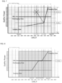
control unit 130 may newly calculate a slope of the droop control curve with respect to the newly set operation point, and the operationmode determination unit 132 may determine the charging mode, the discharging mode, or the idle operation mode by comparing the link voltage value and the operation point which are input later. For example, the operationmode determination unit 132 may determine the operation mode as the charging mode when the link voltage value is greater than or equal to the reference voltage value. Alternatively, the operationmode determination unit 132 may determine the operation mode as the discharging mode when the link voltage value is smaller than or equal to the reference voltage value. Alternatively, the operationmode determination unit 132 may determine the operation mode as the idle mode when the link voltage value is equal to the reference voltage value.FIG. 6 illustrates that the required power value of the inverter is 0 [W], and the reference voltage value according to the required power value is set as a default. However, as will be described below, the DC/DC converter 100 according to the embodiment sets the new operation point when receiving the required power value and the reference voltage value from the inverter, and the operationmode determination unit 132 sets the operation mode according to the newly set operation point. - Further, in
FIG. 6 , since the droop control curve includes maximum power, output power may be limited to the maximum power. Specifically, the maximum power may include maximally charged power PCMax and maximally discharged power PDMax. The maximally charged power PCMax may be a power value at which the output power may be maximized when the operation mode is the charging mode. The maximally discharged power PDMax may be a power value at which the output power may be maximized when the operation mode is the discharge mode. - Further, the operation
mode determination unit 132 may determine the operation mode according to a voltage condition of thebattery 200. More specifically, the operationmode determination unit 132 may operate in the charging mode when the voltage of thebattery 200 is greater than or equal to a predetermined voltage. - As another example, the operation
mode determination unit 132 may determine the operation mode and the output power according to a user's control. In this case, the user may determine the operation mode and the output power directly or using communication. - Further, the operation
mode determination unit 132 may select any one example of one example, another example, and still another example to determine the operation mode and the output power. - The
slope calculation unit 133 may calculate the slope of the droop control curve according to the reference voltage value and the required power value. Theslope calculation unit 133 may calculate a right slope based on the reference voltage value, and calculate a left slope based on the reference voltage value. - The
slope calculation unit 133 may calculate the right slope of the droop control curve in which the reference voltage value is an operation point according toEquation 1 below.
- In
Equation 1, Slope1 is the right slope of the droop control curve based on the reference voltage value, PH,Limit is a maximally charged power value, VH,Limit is a starting voltage value of maximally charged power, Pset is the required power value received from the inverter, and Vref is the reference voltage value received from the inverter. - Further, the
slope calculation unit 133 may calculate the left slope of the droop control curve in which the reference voltage value is an operation point according toEquation 2 below.
- In
Equation 2, Slope2 is the left slope of droop control curve based on the reference voltage value, PL,Limit is a maximally discharged power value, VL,Limit is a starting voltage value of maximally discharged power, Pset is the required power value received from the inverter, and Vref is the reference voltage value received from the inverter. - In embodiment, the right slope of the droop control curve may refer to a charging power slope, and the left slope of the droop control curve may refer to a discharging power slope. The charging power slope and the discharging power slope may be different from each other, but are not limited thereto, and may be equal to each other.
- The output power
value calculation unit 134 may calculate the output power value by substituting a difference value between the link voltage value and the reference voltage value into the slope. The output powervalue calculation unit 134 may perform duty value compensation using a target current generation value and a feedback current. The output powervalue calculation unit 134 may calculate an output power value by multiplying a difference value acquired by subtracting the reference voltage value from the link voltage value by the left slope of the droop control curve in the discharging mode. Alternatively, the output powervalue calculation unit 134 may calculate an output power value by multiplying a difference value acquired by subtracting the link voltage value from the reference voltage value by the right slope of the droop control curve in the charging mode. Further, the output powervalue calculation unit 134 may generate a current command by reflecting a target power value to a droop control curve newly generated according to the calculated slope. That is, the current command may be generated by generating a power command according to the link voltage, and compensating for power command values according to the required power value and the reference voltage value of the inverter. The targetcurrent determination unit 135 may determine a target current based on the determined operation mode and output power. The targetcurrent determination unit 135 may determine a final duty using a basic duty value and a current-compensated duty value according to an input/output voltage. The targetcurrent determination unit 135 may receive operation mode output and switch the current command according to the mode. - The
current controller 136 may output the target current value to the battery. Thecurrent controller 136 may include a charging current control unit 1361, a discharging current control unit 1363, and an idle control unit 1362, and each of the control units 1361 to 1363 may operate according to the output operation mode. Thecurrent controller 136 may generate a PWM signal which is a switching signal based on the determined target current. -
FIG. 7 shows a voltage-power plane for describing an operation area of the control unit according to the embodiment. Referring toFIG. 7 , the control unit according to the embodiment sets a new operation point when receiving the required power value and the reference voltage value from the inverter, and calculates a slope of the droop control curve according to the newly set operation point. The calculated slope may be reflected to the droop control curve to generate a new droop control curve, and the control unit may calculate the output power and the target current by substituting the link voltage value into the new droop control curve. -
FIG. 8 shows a voltage-power plane for describing an operation area of the control unit according to the embodiment. - Referring to
FIG. 8 , the control unit may receive a required power value of 0 [W] from the inverter. Further, the input unit may receive a link voltage value of 400 [V] from the direct current link capacitor. - The control unit may calculate a right slope and a left slope of the droop control curve based on the reference voltage value according to the input required power value. In the embodiment, since the required power value is input as 0 [W], the slope of the droop control curve may be calculated as 350, which is an initially set value.
- Next, the control unit may calculate the output power value by calculating a difference value between a reference voltage value of 410 [V] and a link voltage value of 400 [V] which are setting values, and substituting the calculated difference value into the previously calculated slope and adding up the calculated difference value and the required power value. The control unit may calculate the output power value by substituting the difference value into the left slope in the discharging mode, and may calculate the output power value by substituting the difference value into the right slope in the charging mode. In the embodiment, the control unit may calculate an output power value of -3500 [W] by adding up a value of -3500 [W], acquired by substituting the difference value into the calculated slope, and a required power value of 0 [W].
- Next, the control unit may calculate the target current value by dividing the output power value by the battery voltage. In the embodiment, the control unit may calculate a target current value of -35 [A] by dividing an output power value of -3500 [W] by a battery voltage of 100 [V].
-
FIG. 9 shows a voltage-power plane for describing an operation area of the control unit according to the embodiment. - Referring to
FIG. 9 , the input unit may receive a required power value of - 4500 [W] from the inverter. Further, the input unit may receive a link voltage value of 425 [V] from the direct current link capacitor. - The control unit may calculate the right slope and the left slope of the droop control curve based on a reference voltage value of 425 [V] according to the input required power value. In the embodiment, the operation point may be changed according to the required power value and the reference voltage value, and the left slope of the droop control curve may be changed from 350 which is an initial setting value to 71.42 and reflected according to the changed operation point.
- Next, the control unit may calculate the output power value by calculating a difference value between a reference voltage value of 425 [V] and a link voltage value of 425 [V] which are setting values, and substituting the calculated difference value into the previously calculated slope and adding up the calculated difference value and the required power value. The control unit may calculate the output power value by substituting the difference value into the left slope in the discharging mode, and may calculate the output power value by substituting the difference value into the right slope in the charging mode. In the embodiment, the control unit may calculate an output power value of -4500 [W] by adding up a value of 0 [W], acquired by substituting the difference value into the calculated slope, and a required power value of -4500 [W].
- Next, the control unit may calculate the target current value by dividing the output power value by the battery voltage. In the embodiment, the control unit may calculate a target current value of -45 [A] by dividing an output power value of -4500 [W] by a battery voltage of 100 [V].
- The control unit may output the calculated target current value to the battery.
- Like the above, the DC/DC converter according to the embodiment may change the operation point of the DC/DC converter by receiving the required power value from the inverter to newly calculate the slope of the droop control curve, and calculating a current output to the battery according to the droop control curve to which the newly calculated slope is reflected. Further, a quick response is possible without a physical voltage fluctuation, and it is possible to perform driving of charging, discharging, and idle sections in all operation sections.
-
FIG. 10 shows a voltage-power plane for describing an operation area of the control unit according to the embodiment. - Referring to
FIG. 10 , the input unit may receive a required power value of - 4500 [W] from the inverter. Further, the input unit may receive a link voltage value of 425 [V] from the direct current link capacitor. - The control unit may calculate the right slope and the left slope of the droop control curve based on a reference voltage value of 395 [V] according to the input required power value. In the embodiment, the operation point may be changed according to the required power value and the reference voltage value, and the left slope of the droop control curve may be changed from 350 which is an initial setting value to 100 and reflected according to the changed operation point.
- Next, the control unit may calculate the output power value by calculating a difference value between a reference voltage value of 395 [V] and a link voltage value of 425 [V] which are setting values, and substituting the calculated difference value into the previously calculated slope and adding up the calculated difference value and the required power value. The control unit may calculate the output power value by substituting the difference value into the left slope in the discharging mode, and may calculate the output power value by substituting the difference value into the right slope in the charging mode. In the embodiment, the control unit may calculate an output power value of -1500 [W] by adding up a value of 3000 [W] acquired by substituting a difference value of 30 [V] into the
calculated slope 100, and a required power value of -4500 [W]. - Next, the control unit may calculate the target current value by dividing the output power value by the battery voltage. In the embodiment, the control unit may calculate a target current value of -15 [A] by dividing an output power value of -1500 [W] by a battery voltage of 100 [V].
- The control unit may output the calculated target current value to the battery.
- Like the above, the DC/DC converter according to the embodiment may change the operation point of the DC/DC converter by receiving the required power value from the inverter to newly calculate the slope of the droop control curve, and calculating a current output to the battery according to the droop control curve to which the newly calculated slope is reflected. Further, a quick response is possible without a physical voltage fluctuation, and it is possible to perform driving of charging, discharging, and idle sections in all operation sections.
-
FIG. 11 is an operational flow chart of an operation of a DC/DC converter control method according to the embodiment. Referring toFIG. 11 , first, an input unit may receive a required power value from an inverter (S1101). - Next, the input unit may receive a reference voltage value from the inverter (S1102).
- Next, an operation mode determination unit may calculate a threshold voltage which determines a charging mode or a discharging mode according to the reference voltage value and the required power value (S1103).
- Next, a control unit may calculate a slope of a droop control curve according to the reference voltage value and the required power value based on the threshold voltage (S1104).
- Next, the input unit may receive a link voltage value from a direct current link capacitor (S1105).
- Next, the control unit may calculate an output power value by substituting a difference value between the link voltage value and the reference voltage value into the slope (S1106).
- Next, the control unit may calculate a target current value according to the output power value (S1107).
- Next, the control unit may output the target current value to a battery (S1108).
-
FIG. 12 is a view for describing an advantage of expanding the operation area related to the proposed droop control compared to conventional droop control. - Referring to
FIG. 12 , a conventional DC/DC converter has a disadvantage that a charging voltage and a discharging voltage are fixed for each inverter, and accordingly, a charging operation area and a discharging operation area are limited within a predetermined range. In comparison of this, since the DC/DC converter according to the embodiment newly calculates and applies a droop control curve in real time according to an operation point, and thus may be matched with inverters of various manufacturers of which operation areas are different, compatibility and control safety may be improved. - The term '-unit' used in the embodiment refers to software or a hardware component such as a field-programmable gate array (FPGA) or an applicationspecific integrated circuit (ASIC), and the '-unit' performs certain roles. However, the '-unit' is not a meaning limited to the software or hardware. The '-unit' may be configured to be present in an addressable storage medium, and may be configured to play one or more processors. Accordingly, for example, the '-unit' includes components such as software components, object oriented software components, class components, and task components, processes, functions, properties, procedures, subroutines, segments of program code, drivers, firmware, microcode, circuits, data, databases, data structures, tables, arrays, and variables. Functions provided in the components and the '-units' may be combined into a smaller number of components and '-units' or further separated into additional components and '-units'. Further, the components and the '-units' may be implemented to play one or more central processing units (CPUs) in a device or a security multimedia card.
- Although the preferable embodiments of the present invention are described above, those skilled in the art may variously modify and change the present invention within the scope and spirit of the present invention disclosed in the following claims.
Claims (10)
- A direct current/direct current (DC/DC) converter control method, comprising:receiving a required power value from an inverter;receiving a reference voltage value from the inverter;calculating a slope of a droop control curve according to the reference voltage value and the required power value;calculating a threshold voltage which determines a charging mode or a discharging mode according to the reference voltage value and the required power value;receiving a link voltage value from a direct current link capacitor;substituting a difference value between the link voltage value and the reference voltage value into the slope to calculate an output power value; andcalculating a target current value according to the output power value.
- The DC/DC converter control method of claim 1, wherein the calculating of the slope of the droop control curve includes:calculating a right slope based onthe reference voltage value; andcalculating a left slope based onthe reference voltage value.
- The DC/DC converter control method of claim 2, wherein the calculating of the right slope includes calculating the right slope of the droop control curve in which the reference voltage value and the required power value are operation points according to Equation 1 below.

- The DC/DC converter control method of claim 2, wherein the calculating of the left slope includes calculating the left slope of the droop control curve in which the reference voltage value and the required power value are operation points according to Equation 2 below.

- The DC/DC converter control method of claim 1, further comprising outputting the target current value to the battery.
- A direct current/direct current (DC/DC) converter comprising:an input unit configured to receive a required power value and a reference voltage value from an inverter and receive a link voltage value from a direct current link capacitor; anda control unit configured to calculate a slope of a droop control curve according to the reference voltage value and the required power value, substitute a difference value between the link voltage value and the reference voltage value into the slope to calculate an output power value, and calculate a target current value according to the output power value.
- The DC/DC converter of claim 6, wherein the control unit calculates a right slope based on the reference voltage value, and calculates a left slope based on the reference voltage value.
- The DC/DC converter of claim 7, wherein the control unit calculates the right slope of the droop control curve in which the reference voltage value and the required power value are operation points according to Equation 3 below.

- The DC/DC converter of claim 7, wherein the control unit calculates the left slope of the droop control curve in which the reference voltage value and the required power value are operation points according to Equation 4 below.

- The DC/DC converter of claim 6, wherein the control unit outputs the target current value to the battery.
Applications Claiming Priority (2)
| Application Number | Priority Date | Filing Date | Title |
|---|---|---|---|
| KR1020200160979A KR102917939B1 (en) | 2020-11-26 | 2020-11-26 | DC/DC converter and its control method |
| PCT/KR2021/011656 WO2022114464A1 (en) | 2020-11-26 | 2021-08-31 | Direct current/direct current converter and control method thereof |
Publications (2)
| Publication Number | Publication Date |
|---|---|
| EP4254758A1 true EP4254758A1 (en) | 2023-10-04 |
| EP4254758A4 EP4254758A4 (en) | 2024-10-23 |
Family
ID=81754664
Family Applications (1)
| Application Number | Title | Priority Date | Filing Date |
|---|---|---|---|
| EP21898291.6A Pending EP4254758A4 (en) | 2020-11-26 | 2021-08-31 | DC/DC CONVERTERS AND CONTROL METHODS THEREFOR |
Country Status (6)
| Country | Link |
|---|---|
| US (1) | US20240014658A1 (en) |
| EP (1) | EP4254758A4 (en) |
| JP (1) | JP7738067B2 (en) |
| KR (2) | KR102917939B1 (en) |
| CN (1) | CN116670991A (en) |
| WO (1) | WO2022114464A1 (en) |
Families Citing this family (2)
| Publication number | Priority date | Publication date | Assignee | Title |
|---|---|---|---|---|
| CN116418040A (en) * | 2023-04-12 | 2023-07-11 | 上海正泰电源系统有限公司 | Method for controlling energy flow based on bus voltage layering |
| KR20240170320A (en) * | 2023-05-26 | 2024-12-03 | 엘지이노텍 주식회사 | Power Converting Apparatus |
Family Cites Families (12)
| Publication number | Priority date | Publication date | Assignee | Title |
|---|---|---|---|---|
| CN103545810B (en) * | 2013-11-12 | 2015-07-15 | 国家电网公司 | Microgrid inverter sagging automatic control method based on small signal stability analysis |
| JP6256983B2 (en) * | 2014-03-13 | 2018-01-10 | ニチコン株式会社 | Power conditioner with storage battery |
| KR101809787B1 (en) * | 2015-03-10 | 2017-12-15 | 엘에스산전 주식회사 | Electricity providing system including battery energy storage system |
| JP6502758B2 (en) * | 2015-06-15 | 2019-04-17 | 川崎重工業株式会社 | DC stabilized power supply system |
| US10516270B2 (en) * | 2016-01-06 | 2019-12-24 | Enphase Energy, Inc. | Method and apparatus for coordination of generators in droop controlled microgrids using hysteresis |
| JP2017212785A (en) * | 2016-05-24 | 2017-11-30 | 株式会社東芝 | Converter system and control method thereof |
| IT201600131878A1 (en) * | 2016-12-28 | 2018-06-28 | Electro Power Systems Mfg S R L | MICRORETAL CONTROL SYSTEM FOR THE PRODUCTION AND DISTRIBUTION OF ELECTRIC ENERGY FROM DIFFERENT SOURCES OF PRODUCTION, AND ITS CONTROL METHOD |
| JP6771164B2 (en) * | 2017-02-14 | 2020-10-21 | パナソニックIpマネジメント株式会社 | Power converter, power conversion system |
| EP3731394A4 (en) * | 2017-12-22 | 2021-08-25 | LG Innotek Co., Ltd. | POWER SUPPLY SYSTEM INCLUDING A CONTINUOUS-CONTINUOUS CONVERTER AND ITS CONTROL PROCESS |
| KR102459472B1 (en) * | 2018-01-25 | 2022-10-26 | 엘지이노텍 주식회사 | Dc-dc converter and control method of the same |
| KR102078453B1 (en) * | 2018-04-10 | 2020-02-19 | 한국전력공사 | Power sharing method in dc microgrids system |
| KR102112334B1 (en) * | 2018-10-22 | 2020-05-19 | 한국에너지기술연구원 | Power converting apparatus and system for preventing interference between modules in power distribution control, and power converting method using the same |
-
2020
- 2020-11-26 KR KR1020200160979A patent/KR102917939B1/en active Active
-
2021
- 2021-08-31 US US18/254,525 patent/US20240014658A1/en active Pending
- 2021-08-31 EP EP21898291.6A patent/EP4254758A4/en active Pending
- 2021-08-31 CN CN202180078623.9A patent/CN116670991A/en active Pending
- 2021-08-31 JP JP2023532185A patent/JP7738067B2/en active Active
- 2021-08-31 WO PCT/KR2021/011656 patent/WO2022114464A1/en not_active Ceased
-
2026
- 2026-01-21 KR KR1020260011945A patent/KR20260015321A/en active Pending
Also Published As
| Publication number | Publication date |
|---|---|
| JP2023553345A (en) | 2023-12-21 |
| JP7738067B2 (en) | 2025-09-11 |
| WO2022114464A1 (en) | 2022-06-02 |
| KR20220073157A (en) | 2022-06-03 |
| US20240014658A1 (en) | 2024-01-11 |
| KR20260015321A (en) | 2026-02-02 |
| EP4254758A4 (en) | 2024-10-23 |
| KR102917939B1 (en) | 2026-01-26 |
| CN116670991A (en) | 2023-08-29 |
Similar Documents
| Publication | Publication Date | Title |
|---|---|---|
| US20230198261A1 (en) | Power supply system including dc-to-dc converter and control method therefor | |
| US11462933B2 (en) | Power storage module and power supply system | |
| EP2341409B1 (en) | Maximum power point tracking apparatus for a renewable energy storage system and maximum power point tracking method | |
| US9653924B2 (en) | Battery system | |
| JP5208374B2 (en) | Grid interconnection power conditioner and grid interconnection power system | |
| US9337682B2 (en) | Charging control device, solar power generation system and charging control method | |
| US11601006B2 (en) | Control of DC voltage distribution system | |
| CN102195312A (en) | A battery system | |
| KR20200048913A (en) | Stand-alone household energy storage system based on waste battery | |
| US11916511B1 (en) | Solar-battery integrated DC system | |
| KR20260015321A (en) | DC/DC converter and its control method | |
| KR20230056968A (en) | Energy storage system including battery racks and photovolatic modules and operating method thereof | |
| EP4583347A1 (en) | Energy storage system having multiple devices connected in parallel and charging and discharging control method thereof | |
| JP2014106935A (en) | Power generation system | |
| EP2830183B1 (en) | Power consumption mode guiding device and system | |
| US20250373005A1 (en) | Direct current/direct current converter and control method thereof | |
| US8942017B2 (en) | Energy storage system and method thereof | |
| US11967840B2 (en) | Power supply system | |
| KR101042746B1 (en) | Bidirectional Inverters in Renewable Energy Storage Systems | |
| JP6993300B2 (en) | Power storage system | |
| JP2022072945A (en) | Storage battery system | |
| JP2008104253A (en) | Power converter | |
| JP2003169421A (en) | Electric power storage system and its controlling method | |
| JP7835977B2 (en) | Control device and control method | |
| CN117220259A (en) | Inverter control method, inverter and energy storage system |
Legal Events
| Date | Code | Title | Description |
|---|---|---|---|
| STAA | Information on the status of an ep patent application or granted ep patent |
Free format text: STATUS: THE INTERNATIONAL PUBLICATION HAS BEEN MADE |
|
| PUAI | Public reference made under article 153(3) epc to a published international application that has entered the european phase |
Free format text: ORIGINAL CODE: 0009012 |
|
| STAA | Information on the status of an ep patent application or granted ep patent |
Free format text: STATUS: REQUEST FOR EXAMINATION WAS MADE |
|
| 17P | Request for examination filed |
Effective date: 20230525 |
|
| AK | Designated contracting states |
Kind code of ref document: A1 Designated state(s): AL AT BE BG CH CY CZ DE DK EE ES FI FR GB GR HR HU IE IS IT LI LT LU LV MC MK MT NL NO PL PT RO RS SE SI SK SM TR |
|
| DAV | Request for validation of the european patent (deleted) | ||
| DAX | Request for extension of the european patent (deleted) | ||
| REG | Reference to a national code |
Ref country code: DE Ref legal event code: R079 Free format text: PREVIOUS MAIN CLASS: H02M0003000000 Ipc: H02J0003320000 |
|
| A4 | Supplementary search report drawn up and despatched |
Effective date: 20240920 |
|
| RIC1 | Information provided on ipc code assigned before grant |
Ipc: H02M 7/48 20070101ALN20240916BHEP Ipc: H02M 3/335 20060101ALN20240916BHEP Ipc: H02M 1/36 20070101ALN20240916BHEP Ipc: H02M 3/158 20060101ALI20240916BHEP Ipc: H02M 1/32 20070101ALI20240916BHEP Ipc: H02M 1/00 20060101ALI20240916BHEP Ipc: H02J 7/06 20060101ALI20240916BHEP Ipc: H02J 7/00 20060101ALI20240916BHEP Ipc: H02J 3/32 20060101AFI20240916BHEP |