EP4254718A1 - Energy storage system comprising new installation battery rack, and method for controlling same - Google Patents
Energy storage system comprising new installation battery rack, and method for controlling same Download PDFInfo
- Publication number
- EP4254718A1 EP4254718A1 EP22867668.0A EP22867668A EP4254718A1 EP 4254718 A1 EP4254718 A1 EP 4254718A1 EP 22867668 A EP22867668 A EP 22867668A EP 4254718 A1 EP4254718 A1 EP 4254718A1
- Authority
- EP
- European Patent Office
- Prior art keywords
- battery
- racks
- battery racks
- output
- outputs
- Prior art date
- Legal status (The legal status is an assumption and is not a legal conclusion. Google has not performed a legal analysis and makes no representation as to the accuracy of the status listed.)
- Granted
Links
Images



Classifications
-
- H—ELECTRICITY
- H02—GENERATION; CONVERSION OR DISTRIBUTION OF ELECTRIC POWER
- H02J—ELECTRIC POWER NETWORKS; CIRCUIT ARRANGEMENTS OR SYSTEMS FOR SUPPLYING OR DISTRIBUTING ELECTRIC POWER; SYSTEMS FOR STORING ELECTRIC ENERGY
- H02J7/00—Circuit arrangements for charging or discharging batteries or for supplying loads from batteries
- H02J7/80—Circuit arrangements for charging or discharging batteries or for supplying loads from batteries including monitoring or indicating arrangements
- H02J7/82—Control of state of charge [SOC]
-
- G—PHYSICS
- G01—MEASURING; TESTING
- G01R—MEASURING ELECTRIC VARIABLES; MEASURING MAGNETIC VARIABLES
- G01R31/00—Arrangements for testing electric properties; Arrangements for locating electric faults; Arrangements for electrical testing characterised by what is being tested not provided for elsewhere
- G01R31/36—Arrangements for testing, measuring or monitoring the electrical condition of accumulators or electric batteries, e.g. capacity or state of charge [SoC]
- G01R31/382—Arrangements for monitoring battery or accumulator variables, e.g. SoC
-
- G—PHYSICS
- G01—MEASURING; TESTING
- G01R—MEASURING ELECTRIC VARIABLES; MEASURING MAGNETIC VARIABLES
- G01R31/00—Arrangements for testing electric properties; Arrangements for locating electric faults; Arrangements for electrical testing characterised by what is being tested not provided for elsewhere
- G01R31/36—Arrangements for testing, measuring or monitoring the electrical condition of accumulators or electric batteries, e.g. capacity or state of charge [SoC]
- G01R31/392—Determining battery ageing or deterioration, e.g. state of health
-
- H—ELECTRICITY
- H02—GENERATION; CONVERSION OR DISTRIBUTION OF ELECTRIC POWER
- H02J—ELECTRIC POWER NETWORKS; CIRCUIT ARRANGEMENTS OR SYSTEMS FOR SUPPLYING OR DISTRIBUTING ELECTRIC POWER; SYSTEMS FOR STORING ELECTRIC ENERGY
- H02J3/00—Circuit arrangements for AC mains or AC distribution networks
- H02J3/28—Arrangements for balancing of the load in networks by storage of energy
- H02J3/32—Arrangements for balancing of the load in networks by storage of energy using batteries or super capacitors with converting means
-
- H—ELECTRICITY
- H02—GENERATION; CONVERSION OR DISTRIBUTION OF ELECTRIC POWER
- H02J—ELECTRIC POWER NETWORKS; CIRCUIT ARRANGEMENTS OR SYSTEMS FOR SUPPLYING OR DISTRIBUTING ELECTRIC POWER; SYSTEMS FOR STORING ELECTRIC ENERGY
- H02J7/00—Circuit arrangements for charging or discharging batteries or for supplying loads from batteries
-
- H—ELECTRICITY
- H02—GENERATION; CONVERSION OR DISTRIBUTION OF ELECTRIC POWER
- H02J—ELECTRIC POWER NETWORKS; CIRCUIT ARRANGEMENTS OR SYSTEMS FOR SUPPLYING OR DISTRIBUTING ELECTRIC POWER; SYSTEMS FOR STORING ELECTRIC ENERGY
- H02J7/00—Circuit arrangements for charging or discharging batteries or for supplying loads from batteries
- H02J7/60—Circuit arrangements for charging or discharging batteries or for supplying loads from batteries including safety or protection arrangements
-
- H—ELECTRICITY
- H02—GENERATION; CONVERSION OR DISTRIBUTION OF ELECTRIC POWER
- H02J—ELECTRIC POWER NETWORKS; CIRCUIT ARRANGEMENTS OR SYSTEMS FOR SUPPLYING OR DISTRIBUTING ELECTRIC POWER; SYSTEMS FOR STORING ELECTRIC ENERGY
- H02J7/00—Circuit arrangements for charging or discharging batteries or for supplying loads from batteries
- H02J7/80—Circuit arrangements for charging or discharging batteries or for supplying loads from batteries including monitoring or indicating arrangements
- H02J7/84—Control of state of health [SOH]
-
- H—ELECTRICITY
- H02—GENERATION; CONVERSION OR DISTRIBUTION OF ELECTRIC POWER
- H02J—ELECTRIC POWER NETWORKS; CIRCUIT ARRANGEMENTS OR SYSTEMS FOR SUPPLYING OR DISTRIBUTING ELECTRIC POWER; SYSTEMS FOR STORING ELECTRIC ENERGY
- H02J7/00—Circuit arrangements for charging or discharging batteries or for supplying loads from batteries
- H02J7/90—Regulation of charging or discharging current or voltage
- H02J7/933—Regulation of charging or discharging current or voltage the cycle being controlled or terminated in response to electric parameters
-
- H—ELECTRICITY
- H02—GENERATION; CONVERSION OR DISTRIBUTION OF ELECTRIC POWER
- H02J—ELECTRIC POWER NETWORKS; CIRCUIT ARRANGEMENTS OR SYSTEMS FOR SUPPLYING OR DISTRIBUTING ELECTRIC POWER; SYSTEMS FOR STORING ELECTRIC ENERGY
- H02J7/00—Circuit arrangements for charging or discharging batteries or for supplying loads from batteries
- H02J7/90—Regulation of charging or discharging current or voltage
- H02J7/94—Regulation of charging or discharging current or voltage in response to battery current
-
- H—ELECTRICITY
- H02—GENERATION; CONVERSION OR DISTRIBUTION OF ELECTRIC POWER
- H02J—ELECTRIC POWER NETWORKS; CIRCUIT ARRANGEMENTS OR SYSTEMS FOR SUPPLYING OR DISTRIBUTING ELECTRIC POWER; SYSTEMS FOR STORING ELECTRIC ENERGY
- H02J7/00—Circuit arrangements for charging or discharging batteries or for supplying loads from batteries
- H02J7/90—Regulation of charging or discharging current or voltage
- H02J7/971—Regulation of charging or discharging current or voltage the charge cycle being controlled or terminated in response to non-electric parameters
- H02J7/975—Regulation of charging or discharging current or voltage the charge cycle being controlled or terminated in response to non-electric parameters in response to temperature
- H02J7/977—Regulation of charging or discharging current or voltage the charge cycle being controlled or terminated in response to non-electric parameters in response to temperature of the battery
-
- H—ELECTRICITY
- H01—ELECTRIC ELEMENTS
- H01M—PROCESSES OR MEANS, e.g. BATTERIES, FOR THE DIRECT CONVERSION OF CHEMICAL ENERGY INTO ELECTRICAL ENERGY
- H01M10/00—Secondary cells; Manufacture thereof
- H01M10/42—Methods or arrangements for servicing or maintenance of secondary cells or secondary half-cells
- H01M10/44—Methods for charging or discharging
- H01M10/441—Methods for charging or discharging for several batteries or cells simultaneously or sequentially
-
- H—ELECTRICITY
- H01—ELECTRIC ELEMENTS
- H01M—PROCESSES OR MEANS, e.g. BATTERIES, FOR THE DIRECT CONVERSION OF CHEMICAL ENERGY INTO ELECTRICAL ENERGY
- H01M10/00—Secondary cells; Manufacture thereof
- H01M10/42—Methods or arrangements for servicing or maintenance of secondary cells or secondary half-cells
- H01M10/48—Accumulators combined with arrangements for measuring, testing or indicating the condition of cells, e.g. the level or density of the electrolyte
- H01M10/482—Accumulators combined with arrangements for measuring, testing or indicating the condition of cells, e.g. the level or density of the electrolyte for several batteries or cells simultaneously or sequentially
-
- H—ELECTRICITY
- H02—GENERATION; CONVERSION OR DISTRIBUTION OF ELECTRIC POWER
- H02J—ELECTRIC POWER NETWORKS; CIRCUIT ARRANGEMENTS OR SYSTEMS FOR SUPPLYING OR DISTRIBUTING ELECTRIC POWER; SYSTEMS FOR STORING ELECTRIC ENERGY
- H02J2207/00—Details of circuit arrangements for charging or discharging batteries or supplying loads from batteries
- H02J2207/10—Control circuit supply, e.g. means for supplying power to the control circuit
-
- H—ELECTRICITY
- H02—GENERATION; CONVERSION OR DISTRIBUTION OF ELECTRIC POWER
- H02J—ELECTRIC POWER NETWORKS; CIRCUIT ARRANGEMENTS OR SYSTEMS FOR SUPPLYING OR DISTRIBUTING ELECTRIC POWER; SYSTEMS FOR STORING ELECTRIC ENERGY
- H02J2207/00—Details of circuit arrangements for charging or discharging batteries or supplying loads from batteries
- H02J2207/20—Charging or discharging characterised by the power electronics converter
-
- H—ELECTRICITY
- H02—GENERATION; CONVERSION OR DISTRIBUTION OF ELECTRIC POWER
- H02J—ELECTRIC POWER NETWORKS; CIRCUIT ARRANGEMENTS OR SYSTEMS FOR SUPPLYING OR DISTRIBUTING ELECTRIC POWER; SYSTEMS FOR STORING ELECTRIC ENERGY
- H02J3/00—Circuit arrangements for AC mains or AC distribution networks
- H02J3/38—Arrangements for feeding a single network from two or more generators or sources in parallel; Arrangements for feeding already energised networks from additional generators or sources in parallel
- H02J3/46—Controlling the sharing of generated power between the generators, sources or networks
-
- H—ELECTRICITY
- H02—GENERATION; CONVERSION OR DISTRIBUTION OF ELECTRIC POWER
- H02J—ELECTRIC POWER NETWORKS; CIRCUIT ARRANGEMENTS OR SYSTEMS FOR SUPPLYING OR DISTRIBUTING ELECTRIC POWER; SYSTEMS FOR STORING ELECTRIC ENERGY
- H02J7/00—Circuit arrangements for charging or discharging batteries or for supplying loads from batteries
- H02J7/34—Parallel operation in networks using both storage and other DC sources, e.g. providing buffering
- H02J7/342—The other DC source being a battery actively interacting with the first one, i.e. battery to battery charging
-
- H—ELECTRICITY
- H02—GENERATION; CONVERSION OR DISTRIBUTION OF ELECTRIC POWER
- H02J—ELECTRIC POWER NETWORKS; CIRCUIT ARRANGEMENTS OR SYSTEMS FOR SUPPLYING OR DISTRIBUTING ELECTRIC POWER; SYSTEMS FOR STORING ELECTRIC ENERGY
- H02J7/00—Circuit arrangements for charging or discharging batteries or for supplying loads from batteries
- H02J7/485—Circuit arrangements for charging or discharging batteries or for supplying loads from batteries with provisions for charging different types of batteries
-
- H—ELECTRICITY
- H02—GENERATION; CONVERSION OR DISTRIBUTION OF ELECTRIC POWER
- H02J—ELECTRIC POWER NETWORKS; CIRCUIT ARRANGEMENTS OR SYSTEMS FOR SUPPLYING OR DISTRIBUTING ELECTRIC POWER; SYSTEMS FOR STORING ELECTRIC ENERGY
- H02J7/00—Circuit arrangements for charging or discharging batteries or for supplying loads from batteries
- H02J7/50—Circuit arrangements for charging or discharging batteries or for supplying loads from batteries acting upon multiple batteries simultaneously or sequentially
Definitions
- the present invention relates to an energy storage system and a method for controlling the energy storage system, and more particularly, to an energy storage system including new or later installed battery racks and a method for controlling the energy storage system including the new or later installed battery racks.
- An energy storage system relates to various technology, including renewable energy, a battery that stores electric power, and grid power. Recently, as research into smart grid and renewable energy is expanding and the efficiency and the stability of the power system are emphasized, a demand for energy storage systems for power supply and demand control, and power quality improvement is increasing. Depending on a purpose of use, energy storage systems may have different output and capacity. In order to configure a large-capacity energy storage system, a plurality of battery systems may be connected to provide the large-capacity energy storage system.
- the performance of some battery racks may deteriorate over time, and accordingly, new battery racks may be added to existing battery racks so as to supplement the performance of the existing battery racks.
- performance difference may exist between a newly added battery rack and an existing battery rack, and thus, unnecessary rack balancing may be repeated due to the performance difference among the new and existing battery racks.
- the new battery racks may follow the performance of the existing battery racks even though the new battery racks are added for performance compensation of the existing battery rack. In other words, even though new battery racks are added, the maximum performance (e.g. nominal capacity, period of use, etc.) possessed by the new battery racks cannot be fully utilized.
- embodiments of the present disclosure provide an energy storage system including one or more existing battery rack and one or more new battery rack.
- embodiments of the present disclosure also provide an apparatus for controlling a battery system, the battery system including one or more existing battery rack and one or more new battery rack.
- embodiments of the present disclosure also provide a method for controlling an energy storage system including one or more existing battery rack and one or more new battery rack.
- an energy storage system may include a plurality of first battery racks, a plurality of battery protection units configured to manage the plurality of first battery racks respectively, a plurality of second battery racks, a plurality of DC/DC converters configured to manage the plurality of second battery racks respectively, and a battery section controller configured to monitor outputs of the plurality of battery protection units and outputs of the plurality of DC/DC converters, and to control the outputs of the plurality of DC/DC converters.
- the battery section controller may be configured to detect output power values of the plurality of first battery racks which operate in accordance with a charge or discharge command, and to calculate output power values to be output by the second battery racks based on at least one of the outputs of the plurality of first battery racks, information about the plurality of first battery racks, and information about the plurality of second battery racks.
- the information about the plurality of second battery racks may include at least one of a number of the second battery racks, state of health (SOHs), state of charges (SOCs), output currents, output powers, and temperatures of the second battery racks.
- SOHs state of health
- SOCs state of charges
- the battery section controller may be configured to calculate an output weight for each second battery rack using the information about the plurality of second battery racks.
- the battery section controller may also be configured to calculate a power command value for each of the second battery racks based on the output weight for each second battery rack and the number of the second battery racks compared to the total number of battery racks in the energy storage system.
- the battery section controller may stop the outputs of the plurality of DC/DC converters when an output command from a power conversion system indicates to stop a charge/discharge operation.
- the charge or discharge command may be transmitted from an energy management system to a power conversion system of the energy storage system.
- a battery system controller which is connected to a plurality of battery protection units managing a plurality of first battery racks respectively and is connected to a plurality of DC/DC converters managing a plurality of second battery racks respectively, may include at least one processor, and a memory configured to store at least one instruction executed by the at least one processor
- the at least one instruction may include an instruction to monitor outputs of the plurality of battery protection units and outputs of the plurality of DC/DC converters, and an instruction to control the outputs of the plurality of DC/DC converters based on a monitoring result.
- the instruction to monitor outputs of the plurality of battery protection units and outputs of the plurality of DC/DC converters may include an instruction to detect output power values of the plurality of first battery racks which operate in accordance with a charge or discharge command.
- the instruction to control the outputs of the plurality of DC/DC converters based on the monitoring result may include an instruction to calculate the output power values to be output by the second battery racks based on the outputs of the plurality of first battery racks, information about the plurality of first battery racks, and information about the plurality of second battery racks.
- the instruction to control the outputs of the plurality of DC/DC converters based on the monitoring result may include an instruction to calculate a total power command value for the plurality of second battery racks based on the output power values of the plurality of first battery racks and the plurality of second battery racks, a quantity information of the plurality of first battery racks, and a quantity information of the plurality of second battery racks, and an instruction to calculate an individual power command value for each of the plurality of second battery racks based on the output weight for each second battery rack and the total power command value.
- the battery system controller may monitor the charge or discharge command that is transmitted from an energy management system to a power conversion system.
- a method for controlling an energy storage system includes a plurality of first battery racks, a plurality of battery protection units configured to manage the plurality of first battery racks respectively, a plurality of second battery racks, a plurality of DC/DC converters configured to manage the plurality of second battery racks respectively.
- the method may include monitoring outputs of the plurality of battery protection units and outputs of the plurality of DC/DC converters using a battery system controller (BSC), detecting output power values of the plurality of first battery racks which operate in accordance with a charge or discharge command, and calculating output power values to be output by the second battery racks based on at least one of the outputs of the plurality of first battery racks, information about the plurality of first battery racks, and information about the plurality of second battery racks.
- BSC battery system controller
- the calculating output power values to be output by the second battery racks may include calculating a total power command value for the plurality of second battery racks based on the output power values of the plurality of first battery racks and the plurality of second battery racks, a quantity information of the plurality of first battery racks, and a quantity information of the plurality of second battery racks, and calculating an individual power command value for each of the plurality of second battery racks based on the output weight for each second battery rack and the total power command value.
- the information about the plurality of second battery racks may include at least one a number of the second battery racks, State of Healths (SOHs), State of Charges (SOCs), output currents, output powers, and temperatures of the plurality of second battery racks.
- SOHs State of Healths
- SOCs State of Charges
- the method for controlling an energy storage system may further comprise stopping the outputs of the plurality of DC/DC converters when an output command from a power conversion system indicates to stop charge/discharge operation.
- the charge or discharge command may be transmitted from an energy management system to a power conversion system.
- unnecessary or excessive rack balancing can be avoided or reduced when new battery racks are added to an existing energy storage system having existing battery racks.
- the performance of new battery racks can be utilized to the fullest (e.g., 100%).
- the existing energy storage system can be operated with existing methods by modifying only a firmware of the battery section controller without modifying a firmware of an existing power conversion system and an existing power management system.
- first, second, A, B, and the like may be used herein to describe various elements, these elements should not be limited by these terms. These terms are only used to distinguish one element from another. For example, a first element could be termed a second element, and, similarly, a second element could be termed a first element, without departing from the scope of the present invention.
- the term "and/or" includes combinations of a plurality of associated listed items or any of the plurality of associated listed items.
- State of Charge refers to a current state of charge of a battery, represented in percent points [%]
- SOH State of Health
- a battery rack refers to a system of a minimum single structure assembled by connecting module units in series/parallel, module units being set by a battery manufacturer.
- a battery rack can be monitored and controlled by a battery management system (BMS).
- BMS battery management system
- a battery rack may include several battery modules and a battery protection unit or any other protection device.
- a battery bank refers to a group of large-scale battery rack systems configured by connecting several racks in parallel.
- a bank BMS for a battery bank may monitor and control several rack BMSs, each of which manages a battery rack.
- a battery section controller refers to a device that controls the topmost level of a battery system including a battery bank level structure or a multiple bank level structure.
- a battery section controller may also be referred to a battery system controller.
- a nominal capacity refers to a capacity [Ah] of a battery set during development by a battery manufacturer.
- FIG. 1 is a block diagram of a conventional energy storage system.
- a battery cell In an energy storage system (ESS), typically a battery cell is a minimum unit of storing energy or power.
- a series/parallel combination of battery cells may form a battery module, and a plurality of battery modules may form a battery rack.
- a battery rack can be a minimum unit of a battery system as a series/parallel combination of battery modules.
- a battery rack may be referred to as a battery pack.
- a battery rack may include a plurality of battery modules and a battery protection unit (BPU) 10 or any other protection device.
- the battery rack can be monitored and controlled through a rack BMS(RBMS).
- the RBMS may monitor a current, a voltage and a temperature, among others, of each battery rack to be managed, calculate a State Of Charge (SOC) of the battery based on monitoring results, and control charging and discharging of the battery rack.
- SOC State Of Charge
- the battery protection unit (BPU) 10 is a device for protecting the battery rack from an abnormal current and a fault current in the battery rack.
- the BPU may include a main contactor (MC), a fuse, a circuit breaker (CB) or a disconnect switch (DS).
- the BPU 10 may control a battery system rack by rack through on/off controlling the main contactor (MC) based on a control from the Rack BMS.
- the BPU 10 may also protect the battery rack from a short circuit current using a fuse in the event of a short circuit. As such, the battery system can be controlled through a protection device such as a BPU 10 or a switchgear.
- a battery section controller (BSC) 20 is located in each battery section which includes a plurality of batteries, peripheral circuits, and devices to monitor and control objects such as a voltage, a current, a temperature, and a circuit breaker.
- the battery section controller 20 is an uppermost control device in a battery system including at least one battery bank with a plurality of battery racks.
- the battery section controller 20 may also be used as a control device in a battery system having a plurality of bank level structures.
- a power conversion system (PCS) 40 installed in each battery section performs charging/discharging based on a charge/discharge command (e.g., a charge or discharge command) from the energy management system (EMS) 30.
- the power conversion system (PCS) 40 may include a power conversion unit (DC/AC inverter) and a controller.
- the output of each BPU 10 may be connected to the PCS 40 through a DC bus, and the PCS 40 may be connected to a power grid.
- the EMS(or Power Management System (PMS)) 30 may manage the overall energy storage system (ESS).
- the battery system is managed only through protection elements such as a BPU and a switch gear. Thus, it is impossible to control the battery system based on individual characteristics of a battery rack or battery pack, such as battery capacity, SOH, and SOC.
- a plurality of battery racks may serve as voltage sources, and the PCS charges and discharges the battery racks using a constant current (CC) control method or a constant power (CP) control method.
- CC constant current
- CP constant power
- the performances of battery racks are almost similar (if expressed in equivalent resistance, showing similar resistance values), and the charge/discharge current of each rack appears in a similar level.
- some racks may experience degradation over time.
- new racks can be added to the existing energy system so as to supplement the system performance, which may be referred to as augmentation.
- the newly added battery racks also referred to as second battery racks
- existing battery racks also referred to as first battery racks
- the newly added battery racks eventually follow the degraded performance of the existing battery racks. Therefore, even though new battery racks are added, the maximum performance (e.g., nominal capacity, period of use, etc.) of the new battery racks cannot be fully utilized.
- reference to new battery racks includes battery racks that are of new manufacture, but may also inlcude battery racks that are used to augment the existing battery racks at a later point in time that includes a DC/DC converter for DC/DC conversion, and may have been previously used and/or refurbished.
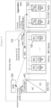
- FIG. 2 is a block diagram of an energy storage system according to embodiments of the present invention.
- FIG. 2 shows the energy storage system in which a plurality of new battery racks are added to an existing energy storage system that was previously being operated.
- an existing energy storage system may include elements similar to the energy storage system shown in FIG. 1 .
- the existing energy storage system may include an energy management system (EMS) 300, a power conversion system (PCS) 400, battery protection units (BPUs) 100, battery racks (old Racks), and a battery section controller 200.
- An energy management system (EMS) may also be referred to as a power management system (PMS), and may manage the energy storage system (ESS) .
- PMS power management system
- the battery section controller (BSC) 200 may play a role in managing a state of each battery rack and informing a supervising system (e.g. EMS) of an output limit of each battery rack.
- the battery section controller (BSC) 200 may be implemented in a form of being mounted and installed on a desktop personal computer (PC) or the like. But such is not required, and a separate device or controller may be used to implement the BSC 200.
- the power conversion system 400 may perform charging/discharging based on charge/discharge commands from the EMS 300.
- the power conversion system 400 may include a DC/AC power converter and a controller.
- New Racks new battery racks
- BPUs 100 operated previously
- the performance of the new battery racks may deteriorate rapidly or a balancing problem among battery racks may occur in the instance the energy storage system is managed by an existing control method that had managed the existing battery racks.
- the energy storage system may use a DC/DC converter 150 exclusively for a newly added battery rack (New Rack) in the augmentation area instead of a battery protection unit (BPU) and avoid or reduce rapid deterioration of the newly added battery rack or a balancing problem among battery racks.
- New Rack a newly added battery rack
- BPU battery protection unit
- the DC/DC converter 150 may include a main body and a DC/DC controller.
- the DC/DC converter 150 may perform DC/DC conversion between a new battery rack (New Rack) and the power conversion system (PCS) 400.
- New Rack new battery rack
- PCS power conversion system
- the DC/DC converter 150 arranged in the augmentation area allows the existing battery racks (Old Racks) in the existing area and the new battery racks (New Racks) in the augmentation area to be electrically separated and operated.
- the output of the DC/DC converter 150 can be actively controlled.
- SOC, SOH, and capacity among the existing battery racks (Old Racks) and the new battery racks (New Racks) it is possible to control the battery output considering the characteristics of each battery rack.
- Each DC/DC converter 150 is connected to the BSC 200 and the PCS 400.
- the BSC 200 may monitor and manage states of the new battery racks (New Racks) with the DC/DC converters 150 and which are disposed in the augmentation area as well as the existing battery racks (Old Racks) with the BPUs 100 and which are disposed in the existing area.
- New Racks new battery racks
- OEMs existing battery racks
- the present invention provides an augmentation techique using a DC/DC converter by modifying only a BSC firmware at a battery area, without modifying any firmware of the PCS or the EMS.
- the new battery racks (New Racks) in the augmentation area may only have the DC/DC converters 150 and not the BPUs 100. Therefore, use a DC/DC converter 150 exclusively for a newly added battery rack (New Rack) in the augmentation area instead of a battery protection unit (BPU) may provide an advantage of avoiding or reducing rapid deterioration of the newly added battery rack or a balancing problem among battery racks, and may provide an advantage of modifying only a BSC firmware at a battery area, without modifying any firmware of the PCS or the EMS.
- BPU battery protection unit
- the EMS 300 may transmit a charge/discharge command for an output power (Pbat*) to the PCS 400.
- the PCS 400 may receive the charge/discharge command (Pbat*) and may direct output of an output power (Pbat*) corresponding to the charge/discharge command (Pbat*).
- the output power (Pbat*) corresponding to the charge/discharge command (Pbat*) may be outputted first (temporarily or for a short time frame) from BPU racks (including the BPU 100 and the existing battery racks (Old Racks)) arranged in the existing area.
- the BSC 200 may be aware of a quantity information such as how many of the BPU racks may be arranged in the existing area and how many of the DC/DC racks (including new battery racks (New Racks) and DC/DC converters 150) are arranged in the augmentation area.
- the BSC 200 may monitor the total output power (Pbat*) from all existing battery racks (Old Racks) connected with the BSC 200. Accordingly, Pbat* refers to a total output power that is demanded from the BPU racks in the existing area and the DC/DC racks in the augmentation area.
- the BSC 200 may calculate an augment power having an output value Paug* to be output by the new battery racks (New Racks) in the augmentation area based on at least the total output power Pbat* of the existing battery racks (BPU Racks or Old Racks) in the existing area and the new battery racks (DC/DC racks or new racks) in the augmentation area, the quantity information of the existing battery racks (BPU racks or Old Racks), and the quantity information of the new battery racks (DC/DC racks or New Racks) .
- the BSC 200 may calculate an output weight for each new battery rack (New Rack) based on a state information (SOC, SOH, etc.) of each new battery rack (New Rack) located in the augmentation area. By multiplying an output weight for each new battery rack (New Rack) by the output value Paug*, a weighted output value of each individual DC/DC rack can be calculated.
- the BSC 200 may calculate the output value Paug* to be generated based on a charge/discharge command (Paug*) for the DC/DC converters 150 based on a residual energy of the DC/DC racks of the new battery racks (New Rack) compared to the BPU racks of the existing battery racks (Old Racks).
- the calculated charge/discharge command Paug* for each DC/DC converter 150 may be transmitted to each DC/DC converter 150 through a communication line 250, and the DC/DC racks collectively output the augment power having the output value Paug* corresponding to the charge/discharge command (Paug*).
- the charge/discharge command for output power Pbat* may also be referred to as a Directive for Output Power Pbat*.
- the charge/discharge command for output power may be expressed or symbolized by a value of the output power Pbat* that is demanded or required by the charge/discharge command that results in the output power Pbat*.
- Pbat* may be used to express the charge/discharge command and the output power depending on the context.
- a charge/discharge command for output value Paug* may also be referred to as a Directive for Output Value Paug*.
- the charge/discharge command for output value may be expressed or symbolized by a value of the output value Paug* that is demanded or required by the charge/discharge command that results in the output value Paug* Accordingly, Paug* may be used to designate the charge/discharge command and the output value depending on context.
- the output of PCS 400 becomes 0.
- the existing BPU area which is in the existing area, relates to passive elements, the output of the battery racks therein changes according to the PCS output.
- the DC/DC area which is in the augmentation area, operates under control of the BSC 200, and thus, the output value Paug* is maintained momentarily. In other words, for a very short moment such as less than 1 second to 1 millisecond, for example, the augmentation area may output the output value Paug* and the existing BPU area may temporarily accept the corresponding output.
- the BSC 200 may detect that the output toward the PCS 400 has become 0, and correct the DC/DC area output command value (Paug*) corresponding to the output value Paug* to 0. Through this process, the output of all racks in the existing BPU area and the DC/DC area becomes 0, and the system operation stops.
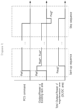
- FIG. 3 illustrates a relationship between an output command value and an output value in each area when the energy storage system is started and stopped according to embodiments of the present invention.
- the BSC 200 may recognize the output power Pbat* provided from the batteries of the old battery racks (old Racks) in the existing area and calculate the output value Paug* to be output by batteries of the new battery racks (New Racks) in the augmentation area to augment the batteries of the old battery racks in order to provide or continually provide the total output power of Pbat*.
- the charge/discharge command for the calculated output value Paug* may then be delivered to the augmentation area.
- the batteries of the old battery racks (Old Racks) in the existing area starts outputting power of (Pbat* - Paug*) because of the provision of the output value Paug* from the batteries of the new battery racks (New Racks) in the augmentation area.
- the value of the total output value of the PCS 400 is maintained as Pbat*, because the EMS 300 transmits a constant command value for the output power of Pbat* to the PCS 400 regardless of whether or not an augmentation has been performed.
- the PCS 400 and the EMS 300 can operate without change of their original operations regardless of augmentation.
- the command value for the output value of the PCS 400 becomes 0 due to a system stop.
- the existing BPU area relates to passive elements, the output of the existing battery racks (Old Racks) in the existing BPU area changes according to the output of the PCS 400.
- the DC/DC area which is an augmentation area, may maintain the output value Paug* until receiving a command from the BSC 200 and control the output to 0 upon receiving a stop command from the BSC 200.
- the existing BPU area temporarily accepts the corresponding output value (-Paug*).
- the output of the DC/DC area becomes 0 by the stop command from the BSC, the output of the existing BPU area also becomes 0.
- FIG. 4 illustrates a concept of calculating an output control weight for each DC/DC converter 150 in an augmentation area according to embodiments of the present invention.
- the BSC 200 may estimate a state of each new battery rack based on information, such as SOC and SOH of the new battery racks (New Racks) in the augmentation area and calculate an output weight for each DC/DC rack based on the state of each DC/DC rack.
- information such as SOC and SOH of the new battery racks (New Racks) in the augmentation area and calculate an output weight for each DC/DC rack based on the state of each DC/DC rack.
- the BSC 200 may receive data, such as SOC, SOH, current, voltage and temperature of each new battery rack (New Rack) from each DC/DC rack.
- the BSC 200 may use this data to calculate output weights ⁇ 1 , ⁇ 2 , ..., ⁇ n for each DC/DC rack, respectively.
- Equation 1 represents an equation for calculating a total output command value Paug* for the augmentation area.
- a unit for the Pbat* and Paug* may be watt (W), for example.
- P aug * n / m + n ⁇ P bat *
- Equation 1 m represents a number (or a quantity) of BPU racks (old), and n may represents a number (or a quantity) of DC/DC racks (new).
- Pbat* represents output power corresponding to a charge/discharge command value Pbat* received from EMS 300.
- Equation 2 represents an equation for calculating the individual output values P DC/DC-1 * to P DC/DC-n * of the DC/DC racks in the augmentation area based on the output value Paug* corresponding to the command value Paug*.
- P DC / DC ⁇ 1 * ⁇ 1 ⁇ P aug *
- the individual output value of the DC/DC rack may be calculated by multiplying the total output value of Paug* for the augmentation area by the output weight for each DC/DC rack.
- a sum of all the output weights a of each DC/DC rack is 1.
- the new battery racks (New Rack) in the augmentation area are battery racks of the same type.
- ( ⁇ i 1 n ( 100 ⁇ SOC Rack # i ) refers to an entire sum of a chargeable value of the entire new battery racks (New Racks) in the augmentation area, and (100 - SOC Rack#j ) refers to a chargeable value of #j new battery rack to which a corresponding output weight of ⁇ is applied, and n is a total number of the new battery racks in the augmentation area.
- the output weight ⁇ for each new battery rack can be determined by considering not only the SOC of each new battery rack but also the SOH of each new battery rack.
- n, i and j can be integers. Accordingly, an amount of augment power to be supplied by an individual new battery rack #j may be provided by the output weight ⁇ j of the new battery rack #j, and the output weight may be included in the charge/discharge command (Paug*).
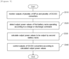
- FIG. 5 is a flowchart of a method for controlling an energy storage system according to embodiments of the present invention.
- the control method of the energy storage system according to the present invention may be performed by a battery section controller in an energy storage system, the energy storage system including a plurality of first battery racks; a plurality of battery protection units configured to manage the plurality of first battery racks respectively; a plurality of second battery racks; a plurality of DC/DC converters configured to manage the plurality of second battery racks respectively.
- the battery section controller may monitor the outputs of the plurality of battery protection units and the plurality of DC/DC converters (operation S510).
- the battery section controller may detect the output power values of the plurality of first battery racks operating according to a charge or discharge command of the energy storage system (operation S520).
- the battery section controller calculates output power values to be output by the plurality of second battery racks (operation S530).
- the output power values to be output by the second battery racks may be calculated using the output power values of the plurality of first battery racks, information about the plurality of first battery racks, and information about the plurality of second battery racks. More specifically, in the operation of calculating the output power values to be output by a plurality of second battery racks, an output weight for each second battery rack can be calculated using information about the plurality of second battery racks. In this operation, the power command value for each of the second battery racks can be calculated based on the output weight for each second battery rack and the number of the second battery racks compared to the total number of battery racks in the energy storage system.
- the information about the plurality of second battery racks includes one or more of the number of the plurality of second battery racks, SOHs, SOCs, output currents, output powers, and temperatures of second battery racks.
- the outputs of the plurality of DC/DC converters may be controlled according to the calculated output power value (operation S540).
- FIG. 6 is a schematic drawing of a battery section controller according to embodiments of the present invention.
- the battery section controller 200 may include at least one processor, a memory configured to store at least one instruction executed by the at least one processor.
- the at least one instruction may be an instruction to monitor outputs of the plurality of battery protection units and outputs of the plurality of DC/DC converters, and an instruction to control the outputs of the plurality of DC/DC converters based on a monitoring result to augment the outputs of the plurality of battery protection units.
- the processor may execute the at least one instruction stored in the memory.
- the processor may mean a central processing unit (CPU), a graphics processing unit (GPU), or a dedicated processor on which methods according to embodiments of the present invention are performed.
- the memory (or storage device) may comprise at least one of a volatile storage medium and a non-volatile storage medium.
- the memory may include at least one of read only memory (ROM) and random access memory (RAM).
- the operations of the method according to the embodiments of the present invention may be implemented as a computer-readable program or code on a computer-readable recording medium.
- the computer-readable recording medium includes all types of recording devices in which data readable by a computer system is stored.
- the computer-readable recording medium may be distributed in a network-connected computer system to store and execute computer-readable programs or codes in a distributed manner.
- Examples of the computer readable medium may include a hardware device such as ROM, RAM, and flash memory, which are specifically configured to store and execute the program instructions.
- Examples of the program instructions include machine codes made by, for example, a compiler, as well as high-level language codes executable by a computer, using an interpreter.
- a block or apparatus corresponds to a method step or feature of a method step.
- aspects described in the context of a method may also represent a feature of a corresponding block or item or a corresponding apparatus.
- Some or all of the method steps may be performed by (or using) a hardware device, such as, for example, a microprocessor, a programmable computer, or an electronic circuit. In some embodiments, one or more of the most important method steps may be performed by such an apparatus.
Landscapes
- Engineering & Computer Science (AREA)
- Power Engineering (AREA)
- Physics & Mathematics (AREA)
- General Physics & Mathematics (AREA)
- Charge And Discharge Circuits For Batteries Or The Like (AREA)
- Health & Medical Sciences (AREA)
- General Health & Medical Sciences (AREA)
- Medical Informatics (AREA)
Abstract
Description
- This application claims priority to and the benefit of
Korean Patent Application No.10-2021-0119406 filed in the Korean Intellectual Property Office on September 8, 2021 - The present invention relates to an energy storage system and a method for controlling the energy storage system, and more particularly, to an energy storage system including new or later installed battery racks and a method for controlling the energy storage system including the new or later installed battery racks.
- An energy storage system relates to various technology, including renewable energy, a battery that stores electric power, and grid power. Recently, as research into smart grid and renewable energy is expanding and the efficiency and the stability of the power system are emphasized, a demand for energy storage systems for power supply and demand control, and power quality improvement is increasing. Depending on a purpose of use, energy storage systems may have different output and capacity. In order to configure a large-capacity energy storage system, a plurality of battery systems may be connected to provide the large-capacity energy storage system.
- In an energy storage system, the performance of some battery racks may deteriorate over time, and accordingly, new battery racks may be added to existing battery racks so as to supplement the performance of the existing battery racks. However, performance difference may exist between a newly added battery rack and an existing battery rack, and thus, unnecessary rack balancing may be repeated due to the performance difference among the new and existing battery racks. Here, a problem arises that the new battery racks may follow the performance of the existing battery racks even though the new battery racks are added for performance compensation of the existing battery rack. In other words, even though new battery racks are added, the maximum performance (e.g. nominal capacity, period of use, etc.) possessed by the new battery racks cannot be fully utilized.
- To obviate one or more problems of the related art, embodiments of the present disclosure provide an energy storage system including one or more existing battery rack and one or more new battery rack.
- To obviate one or more problems of the related art, embodiments of the present disclosure also provide an apparatus for controlling a battery system, the battery system including one or more existing battery rack and one or more new battery rack.
- To obviate one or more problems of the related art, embodiments of the present disclosure also provide a method for controlling an energy storage system including one or more existing battery rack and one or more new battery rack.
- In order to achieve the objective of the present disclosure, an energy storage system may include a plurality of first battery racks, a plurality of battery protection units configured to manage the plurality of first battery racks respectively, a plurality of second battery racks, a plurality of DC/DC converters configured to manage the plurality of second battery racks respectively, and a battery section controller configured to monitor outputs of the plurality of battery protection units and outputs of the plurality of DC/DC converters, and to control the outputs of the plurality of DC/DC converters.
- In the embodiment, the battery section controller may be configured to detect output power values of the plurality of first battery racks which operate in accordance with a charge or discharge command, and to calculate output power values to be output by the second battery racks based on at least one of the outputs of the plurality of first battery racks, information about the plurality of first battery racks, and information about the plurality of second battery racks.
- Here, the information about the plurality of second battery racks may include at least one of a number of the second battery racks, state of health (SOHs), state of charges (SOCs), output currents, output powers, and temperatures of the second battery racks.
- In addition, the battery section controller may be configured to calculate an output weight for each second battery rack using the information about the plurality of second battery racks.
- The battery section controller may also be configured to calculate a power command value for each of the second battery racks based on the output weight for each second battery rack and the number of the second battery racks compared to the total number of battery racks in the energy storage system.
- The battery section controller may stop the outputs of the plurality of DC/DC converters when an output command from a power conversion system indicates to stop a charge/discharge operation.
- The charge or discharge command may be transmitted from an energy management system to a power conversion system of the energy storage system.
- According to another embodiment of the present disclosure, a battery system controller, which is connected to a plurality of battery protection units managing a plurality of first battery racks respectively and is connected to a plurality of DC/DC converters managing a plurality of second battery racks respectively, may include at least one processor, and a memory configured to store at least one instruction executed by the at least one processor
- Here, the at least one instruction may include an instruction to monitor outputs of the plurality of battery protection units and outputs of the plurality of DC/DC converters, and an instruction to control the outputs of the plurality of DC/DC converters based on a monitoring result.
- The instruction to monitor outputs of the plurality of battery protection units and outputs of the plurality of DC/DC converters may include an instruction to detect output power values of the plurality of first battery racks which operate in accordance with a charge or discharge command.
- The instruction to control the outputs of the plurality of DC/DC converters based on the monitoring result may include an instruction to calculate the output power values to be output by the second battery racks based on the outputs of the plurality of first battery racks, information about the plurality of first battery racks, and information about the plurality of second battery racks.
- The instruction to control the outputs of the plurality of DC/DC converters based on the monitoring result may include an instruction to calculate a total power command value for the plurality of second battery racks based on the output power values of the plurality of first battery racks and the plurality of second battery racks, a quantity information of the plurality of first battery racks, and a quantity information of the plurality of second battery racks, and an instruction to calculate an individual power command value for each of the plurality of second battery racks based on the output weight for each second battery rack and the total power command value.
- The battery system controller may monitor the charge or discharge command that is transmitted from an energy management system to a power conversion system.
- According to another embodiment of the present disclosure, a method for controlling an energy storage system is provided where the energy storage system includes a plurality of first battery racks, a plurality of battery protection units configured to manage the plurality of first battery racks respectively, a plurality of second battery racks, a plurality of DC/DC converters configured to manage the plurality of second battery racks respectively. The method may include monitoring outputs of the plurality of battery protection units and outputs of the plurality of DC/DC converters using a battery system controller (BSC), detecting output power values of the plurality of first battery racks which operate in accordance with a charge or discharge command, and calculating output power values to be output by the second battery racks based on at least one of the outputs of the plurality of first battery racks, information about the plurality of first battery racks, and information about the plurality of second battery racks.
- The calculating output power values to be output by the second battery racks may include calculating a total power command value for the plurality of second battery racks based on the output power values of the plurality of first battery racks and the plurality of second battery racks, a quantity information of the plurality of first battery racks, and a quantity information of the plurality of second battery racks, and calculating an individual power command value for each of the plurality of second battery racks based on the output weight for each second battery rack and the total power command value.
- Here, the information about the plurality of second battery racks may include at least one a number of the second battery racks, State of Healths (SOHs), State of Charges (SOCs), output currents, output powers, and temperatures of the plurality of second battery racks.
- The method for controlling an energy storage system may further comprise stopping the outputs of the plurality of DC/DC converters when an output command from a power conversion system indicates to stop charge/discharge operation.
- The charge or discharge command may be transmitted from an energy management system to a power conversion system.
- According to embodiments of the present disclosure, unnecessary or excessive rack balancing can be avoided or reduced when new battery racks are added to an existing energy storage system having existing battery racks.
- Accordingly, the performance of new battery racks can be utilized to the fullest (e.g., 100%).
- In addition, the existing energy storage system can be operated with existing methods by modifying only a firmware of the battery section controller without modifying a firmware of an existing power conversion system and an existing power management system.
-
-
FIG. 1 is a block diagram of a conventional energy storage system. -
FIG. 2 is a block diagram of an energy storage system according to embodiments of the present invention. -
FIG. 3 illustrates a relationship between an output command value and output values in each of an existing area and an augmentation area when the energy storage system is started and stopped according to embodiments of the present invention. -
FIG. 4 illustrates a concept of calculating an output control weight for each DC/DC converter in the augmentation are according to embodiments of the present invention. -
FIG. 5 is a flowchart of a method for controlling an energy storage system according to embodiments of the present invention. -
FIG. 6 is a schematic drawing of a battery section controller according to embodiments of the present invention. - The present invention may be modified in various forms and have various embodiments, and specific embodiments thereof are shown by way of example in the drawings and will be described in detail below. It should be understood, however, that there is no intent to limit the present invention to the specific embodiments, but on the contrary, the present invention is to cover all modifications, equivalents, and alternatives falling within the spirit and technical scope of the present invention. Like reference numerals refer to like elements throughout the description of the figures.
- It will be understood that, although the terms such as first, second, A, B, and the like may be used herein to describe various elements, these elements should not be limited by these terms. These terms are only used to distinguish one element from another. For example, a first element could be termed a second element, and, similarly, a second element could be termed a first element, without departing from the scope of the present invention. As used herein, the term "and/or" includes combinations of a plurality of associated listed items or any of the plurality of associated listed items.
- It will be understood that when an element is referred to as being "coupled" or "connected" to another element, it can be directly coupled or connected to the other element or an intervening element may be present. In contrast, when an element is referred to as being "directly coupled" or "directly connected" to another element, there is no intervening element present.
- The terms used herein is for the purpose of describing specific embodiments only and are not intended to limit the present invention. As used herein, the singular forms "a", "an" and "the" are intended to include the plural forms as well, unless the context clearly indicates otherwise. It will be further understood that the terms "comprises", "comprising", "includes", "including" and/or "having", when used herein, specify the presence of stated features, integers, steps, operations, constitutional elements, components and/or combinations thereof, but do not preclude the presence or addition of one or more other features, integers, steps, operations, constitutional elements, components, and/or combinations thereof.
- Unless otherwise defined, all terms used herein, including technical and scientific terms, have the same meanings as commonly understood by one skilled in the art to which the present invention belongs. It will be further understood that terms, such as those defined in commonly used dictionaries, should be interpreted as having meanings that are consistent with their meanings in the context of the relevant art and will not be interpreted in an idealized or overly formal sense unless expressly so defined herein.
- Some terms used herein are defined as follows.
- State of Charge (SOC) refers to a current state of charge of a battery, represented in percent points [%], and State of Health (SOH) may be a current condition of a battery compared to its ideal or original conditions, represented in percent points [%].
- A battery rack refers to a system of a minimum single structure assembled by connecting module units in series/parallel, module units being set by a battery manufacturer. A battery rack can be monitored and controlled by a battery management system (BMS). A battery rack may include several battery modules and a battery protection unit or any other protection device.
- A battery bank refers to a group of large-scale battery rack systems configured by connecting several racks in parallel. A bank BMS for a battery bank may monitor and control several rack BMSs, each of which manages a battery rack.
- A battery section controller (BSC) refers to a device that controls the topmost level of a battery system including a battery bank level structure or a multiple bank level structure. A battery section controller may also be referred to a battery system controller.
- A nominal capacity (Nominal Capa.) refers to a capacity [Ah] of a battery set during development by a battery manufacturer.
- Hereinafter, exemplary embodiments of the present invention will be described in detail with reference to the accompanying drawings.
-
FIG. 1 is a block diagram of a conventional energy storage system. - In an energy storage system (ESS), typically a battery cell is a minimum unit of storing energy or power. A series/parallel combination of battery cells may form a battery module, and a plurality of battery modules may form a battery rack. In other words, a battery rack can be a minimum unit of a battery system as a series/parallel combination of battery modules. Here, depending on a device or a system in which the battery is used, a battery rack may be referred to as a battery pack.
- Referring to
FIG. 1 , a battery rack may include a plurality of battery modules and a battery protection unit (BPU) 10 or any other protection device. The battery rack can be monitored and controlled through a rack BMS(RBMS). The RBMS may monitor a current, a voltage and a temperature, among others, of each battery rack to be managed, calculate a State Of Charge (SOC) of the battery based on monitoring results, and control charging and discharging of the battery rack. - The battery protection unit (BPU) 10 is a device for protecting the battery rack from an abnormal current and a fault current in the battery rack. The BPU may include a main contactor (MC), a fuse, a circuit breaker (CB) or a disconnect switch (DS). The
BPU 10 may control a battery system rack by rack through on/off controlling the main contactor (MC) based on a control from the Rack BMS. TheBPU 10 may also protect the battery rack from a short circuit current using a fuse in the event of a short circuit. As such, the battery system can be controlled through a protection device such as aBPU 10 or a switchgear. - A battery section controller (BSC) 20 is located in each battery section which includes a plurality of batteries, peripheral circuits, and devices to monitor and control objects such as a voltage, a current, a temperature, and a circuit breaker. The
battery section controller 20 is an uppermost control device in a battery system including at least one battery bank with a plurality of battery racks. Thebattery section controller 20 may also be used as a control device in a battery system having a plurality of bank level structures. - A power conversion system (PCS) 40 installed in each battery section performs charging/discharging based on a charge/discharge command (e.g., a charge or discharge command) from the energy management system (EMS) 30. The power conversion system (PCS) 40 may include a power conversion unit (DC/AC inverter) and a controller. The output of each
BPU 10 may be connected to thePCS 40 through a DC bus, and thePCS 40 may be connected to a power grid. In addition, the EMS(or Power Management System (PMS)) 30 may manage the overall energy storage system (ESS). - In a conventional battery system as shown in
FIG. 1 , the battery system is managed only through protection elements such as a BPU and a switch gear. Thus, it is impossible to control the battery system based on individual characteristics of a battery rack or battery pack, such as battery capacity, SOH, and SOC. - In such an energy storage system, a plurality of battery racks may serve as voltage sources, and the PCS charges and discharges the battery racks using a constant current (CC) control method or a constant power (CP) control method. At the initial installation of the battery racks, the performances of battery racks are almost similar (if expressed in equivalent resistance, showing similar resistance values), and the charge/discharge current of each rack appears in a similar level. However, some racks may experience degradation over time. In this instance, new racks can be added to the existing energy system so as to supplement the system performance, which may be referred to as augmentation.
- Here, there may be a performance difference between newly added battery racks (also referred to as second battery racks) and existing battery racks (also referred to as first battery racks), which may cause repeated and unnecessary (or excessive) rack balancing according to an existing control method, and thus, the newly added battery racks eventually follow the degraded performance of the existing battery racks. Therefore, even though new battery racks are added, the maximum performance (e.g., nominal capacity, period of use, etc.) of the new battery racks cannot be fully utilized. In embodiments of the present invention, reference to new battery racks includes battery racks that are of new manufacture, but may also inlcude battery racks that are used to augment the existing battery racks at a later point in time that includes a DC/DC converter for DC/DC conversion, and may have been previously used and/or refurbished.
-
FIG. 2 is a block diagram of an energy storage system according to embodiments of the present invention. -
FIG. 2 shows the energy storage system in which a plurality of new battery racks are added to an existing energy storage system that was previously being operated. In embodiments of the present invention, an existing energy storage system may include elements similar to the energy storage system shown inFIG. 1 . The existing energy storage system may include an energy management system (EMS) 300, a power conversion system (PCS) 400, battery protection units (BPUs) 100, battery racks (old Racks), and abattery section controller 200. An energy management system (EMS) may also be referred to as a power management system (PMS), and may manage the energy storage system (ESS) . - The battery section controller (BSC) 200 may play a role in managing a state of each battery rack and informing a supervising system (e.g. EMS) of an output limit of each battery rack. The battery section controller (BSC) 200 may be implemented in a form of being mounted and installed on a desktop personal computer (PC) or the like. But such is not required, and a separate device or controller may be used to implement the
BSC 200. Thepower conversion system 400 may perform charging/discharging based on charge/discharge commands from theEMS 300. Thepower conversion system 400 may include a DC/AC power converter and a controller. - When an augmentation is implemented in which one or more new battery racks (New Racks) are added to supplement a plurality of battery racks (Old Racks) and
BPUs 100 operated previously, that is, when existing battery racks (Old Racks) and new battery racks (New Racks) coexist by augmentation, the performance of the new battery racks may deteriorate rapidly or a balancing problem among battery racks may occur in the instance the energy storage system is managed by an existing control method that had managed the existing battery racks. - Therefore, the energy storage system according to embodiments of the present invention may use a DC/
DC converter 150 exclusively for a newly added battery rack (New Rack) in the augmentation area instead of a battery protection unit (BPU) and avoid or reduce rapid deterioration of the newly added battery rack or a balancing problem among battery racks. - The DC/
DC converter 150 may include a main body and a DC/DC controller. The DC/DC converter 150 may perform DC/DC conversion between a new battery rack (New Rack) and the power conversion system (PCS) 400. - The DC/
DC converter 150 arranged in the augmentation area allows the existing battery racks (Old Racks) in the existing area and the new battery racks (New Racks) in the augmentation area to be electrically separated and operated. The output of the DC/DC converter 150 can be actively controlled. Thus, even if there is a difference in SOC, SOH, and capacity among the existing battery racks (Old Racks) and the new battery racks (New Racks), it is possible to control the battery output considering the characteristics of each battery rack. - Each DC/
DC converter 150 is connected to theBSC 200 and thePCS 400. TheBSC 200 may monitor and manage states of the new battery racks (New Racks) with the DC/DC converters 150 and which are disposed in the augmentation area as well as the existing battery racks (Old Racks) with theBPUs 100 and which are disposed in the existing area. - Meanwhile, from a point of view of an end user who use services provided by the energy storage system (ESS), whether batteries can be operated without changing the existing PCS and EMS is one of importance for interoperability and convenience.
- The present invention provides an augmentation techique using a DC/DC converter by modifying only a BSC firmware at a battery area, without modifying any firmware of the PCS or the EMS.
- In embodiments of the present invention, the new battery racks (New Racks) in the augmentation area, and used for augmenting the existing battery racks (Old Racks), may only have the DC/
DC converters 150 and not theBPUs 100. Therefore, use a DC/DC converter 150 exclusively for a newly added battery rack (New Rack) in the augmentation area instead of a battery protection unit (BPU) may provide an advantage of avoiding or reducing rapid deterioration of the newly added battery rack or a balancing problem among battery racks, and may provide an advantage of modifying only a BSC firmware at a battery area, without modifying any firmware of the PCS or the EMS. - To further explain the augmentation technique, a start-up sequence of an energy storage system according to embodiments of the present invention will be described.
- Referring to
FIG. 2 , theEMS 300 may transmit a charge/discharge command for an output power (Pbat*) to thePCS 400. ThePCS 400 may receive the charge/discharge command (Pbat*) and may direct output of an output power (Pbat*) corresponding to the charge/discharge command (Pbat*). At this moment, the output power (Pbat*) corresponding to the charge/discharge command (Pbat*) may be outputted first (temporarily or for a short time frame) from BPU racks (including theBPU 100 and the existing battery racks (Old Racks)) arranged in the existing area. - Here, the
BSC 200 may be aware of a quantity information such as how many of the BPU racks may be arranged in the existing area and how many of the DC/DC racks (including new battery racks (New Racks) and DC/DC converters 150) are arranged in the augmentation area. TheBSC 200 may monitor the total output power (Pbat*) from all existing battery racks (Old Racks) connected with theBSC 200. Accordingly, Pbat* refers to a total output power that is demanded from the BPU racks in the existing area and the DC/DC racks in the augmentation area. - Meanwhile, the
BSC 200 may calculate an augment power having an output value Paug* to be output by the new battery racks (New Racks) in the augmentation area based on at least the total output power Pbat* of the existing battery racks (BPU Racks or Old Racks) in the existing area and the new battery racks (DC/DC racks or new racks) in the augmentation area, the quantity information of the existing battery racks (BPU racks or Old Racks), and the quantity information of the new battery racks (DC/DC racks or New Racks) . - Furthermore, the
BSC 200 may calculate an output weight for each new battery rack (New Rack) based on a state information (SOC, SOH, etc.) of each new battery rack (New Rack) located in the augmentation area. By multiplying an output weight for each new battery rack (New Rack) by the output value Paug*, a weighted output value of each individual DC/DC rack can be calculated. In other words, theBSC 200 may calculate the output value Paug* to be generated based on a charge/discharge command (Paug*) for the DC/DC converters 150 based on a residual energy of the DC/DC racks of the new battery racks (New Rack) compared to the BPU racks of the existing battery racks (Old Racks). The calculated charge/discharge command Paug* for each DC/DC converter 150 may be transmitted to each DC/DC converter 150 through acommunication line 250, and the DC/DC racks collectively output the augment power having the output value Paug* corresponding to the charge/discharge command (Paug*). - In embodiments of the present invention, the charge/discharge command for output power Pbat* may also be referred to as a Directive for Output Power Pbat*. In this regard, the charge/discharge command for output power may be expressed or symbolized by a value of the output power Pbat* that is demanded or required by the charge/discharge command that results in the output power Pbat*. Accordingly, Pbat* may be used to express the charge/discharge command and the output power depending on the context. In a similar manner, a charge/discharge command for output value Paug* may also be referred to as a Directive for Output Value Paug*. In this regard, the charge/discharge command for output value may be expressed or symbolized by a value of the output value Paug* that is demanded or required by the charge/discharge command that results in the output value Paug* Accordingly, Paug* may be used to designate the charge/discharge command and the output value depending on context.
- The series of processes in the start-up sequence described above is performed within a very short time after the output of the PCS is initiated.
- Next, a stop sequence of the energy storage system will be described.
- When the energy storage system (ESS) is stopped or to be stopped, the output of
PCS 400 becomes 0. At this moment, since the existing BPU area, which is in the existing area, relates to passive elements, the output of the battery racks therein changes according to the PCS output. However, the DC/DC area, which is in the augmentation area, operates under control of theBSC 200, and thus, the output value Paug* is maintained momentarily. In other words, for a very short moment such as less than 1 second to 1 millisecond, for example, the augmentation area may output the output value Paug* and the existing BPU area may temporarily accept the corresponding output. In the meantime, theBSC 200 may detect that the output toward thePCS 400 has become 0, and correct the DC/DC area output command value (Paug*) corresponding to the output value Paug* to 0. Through this process, the output of all racks in the existing BPU area and the DC/DC area becomes 0, and the system operation stops. -
FIG. 3 illustrates a relationship between an output command value and an output value in each area when the energy storage system is started and stopped according to embodiments of the present invention. - In a startup sequence, when the total output power of Pbat* is to be output from the energy storage system, the output power of Pbat* is first output from batteries of the old battery racks (Old Racks) in the existing area through the
PCS 400 that receives a charge/discharge command (Pbat*) from theEMS 300, theBSC 200 may recognize the output power Pbat* provided from the batteries of the old battery racks (old Racks) in the existing area and calculate the output value Paug* to be output by batteries of the new battery racks (New Racks) in the augmentation area to augment the batteries of the old battery racks in order to provide or continually provide the total output power of Pbat*. The charge/discharge command for the calculated output value Paug* may then be delivered to the augmentation area. - When the augmentation area outputs the output value of Paug* based on the charge/discharge command for the calculated output value Paug*, the batteries of the old battery racks (Old Racks) in the existing area starts outputting power of (Pbat* - Paug*) because of the provision of the output value Paug* from the batteries of the new battery racks (New Racks) in the augmentation area. Here, the value of the total output value of the
PCS 400 is maintained as Pbat*, because theEMS 300 transmits a constant command value for the output power of Pbat* to thePCS 400 regardless of whether or not an augmentation has been performed. As described above, according to the present invention, thePCS 400 and theEMS 300 can operate without change of their original operations regardless of augmentation. - On the other hand, in a stop sequence, the command value for the output value of the
PCS 400 becomes 0 due to a system stop. Since the existing BPU area relates to passive elements, the output of the existing battery racks (Old Racks) in the existing BPU area changes according to the output of thePCS 400. The DC/DC area, which is an augmentation area, may maintain the output value Paug* until receiving a command from theBSC 200 and control the output to 0 upon receiving a stop command from theBSC 200. For a short time during which the augmentation area outputs the output value Paug*, the existing BPU area temporarily accepts the corresponding output value (-Paug*). When the output of the DC/DC area becomes 0 by the stop command from the BSC, the output of the existing BPU area also becomes 0. -
FIG. 4 illustrates a concept of calculating an output control weight for each DC/DC converter 150 in an augmentation area according to embodiments of the present invention. - According to an embodiment of the present invention, the
BSC 200 may estimate a state of each new battery rack based on information, such as SOC and SOH of the new battery racks (New Racks) in the augmentation area and calculate an output weight for each DC/DC rack based on the state of each DC/DC rack. - Specifically, referring to
FIG. 4 , theBSC 200 may receive data, such as SOC, SOH, current, voltage and temperature of each new battery rack (New Rack) from each DC/DC rack. TheBSC 200 may use this data to calculate output weights α1, α2, ..., αn for each DC/DC rack, respectively. -
Equation 1 below represents an equation for calculating a total output command value Paug* for the augmentation area. In embodiments of the present invention, a unit for the Pbat* and Paug* may be watt (W), for example.
- In
Equation 1, m represents a number (or a quantity) of BPU racks (old), and n may represents a number (or a quantity) of DC/DC racks (new). In addition, Pbat* represents output power corresponding to a charge/discharge command value Pbat* received fromEMS 300. -
Equation 2 represents an equation for calculating the individual output values PDC/DC-1* to PDC/DC-n* of the DC/DC racks in the augmentation area based on the output value Paug* corresponding to the command value Paug*.
- In
Equation 2, the individual output value of the DC/DC rack may be calculated by multiplying the total output value of Paug* for the augmentation area by the output weight for each DC/DC rack. Here, a sum of all the output weights a of each DC/DC rack is 1. - In one embodiment, it is assumed that the new battery racks (New Rack) in the augmentation area are battery racks of the same type.
- In this instance, batteries in the augmentation area of the same type and having similar SOH may have an output weight αj of the new battery rack #j be defined with the following equation, when charging:

- In the above equation 3, (

- In addition, when the batteries in the augmentation area are of the same type and have similar SOH, the output weight of α for each new battery rack during a discharge may be determined as a ratio of the SOC of the corresponding new battery rack to the SOC of the entire new battery racks in the augmentation area. That is, it can be defined as the following equation:

- On the other hand, when the battery is of the same type but the new battery racks have different SOHs, the output weight α for each new battery rack can be determined by considering not only the SOC of each new battery rack but also the SOH of each new battery rack.
- For example, the output weight α for each new battery rack during charging may be defined as follows:

- In addition, the output weight for each battery rack during discharge may be defined as follows:

- In the above equations, n, i and j can be integers. Accordingly, an amount of augment power to be supplied by an individual new battery rack #j may be provided by the output weight αj of the new battery rack #j, and the output weight may be included in the charge/discharge command (Paug*).
-
FIG. 5 is a flowchart of a method for controlling an energy storage system according to embodiments of the present invention. - The control method of the energy storage system according to the present invention may be performed by a battery section controller in an energy storage system, the energy storage system including a plurality of first battery racks; a plurality of battery protection units configured to manage the plurality of first battery racks respectively; a plurality of second battery racks; a plurality of DC/DC converters configured to manage the plurality of second battery racks respectively.
- The battery section controller may monitor the outputs of the plurality of battery protection units and the plurality of DC/DC converters (operation S510).
- The battery section controller may detect the output power values of the plurality of first battery racks operating according to a charge or discharge command of the energy storage system (operation S520).
- Thereafter, the battery section controller calculates output power values to be output by the plurality of second battery racks (operation S530). Here, the output power values to be output by the second battery racks may be calculated using the output power values of the plurality of first battery racks, information about the plurality of first battery racks, and information about the plurality of second battery racks. More specifically, in the operation of calculating the output power values to be output by a plurality of second battery racks, an output weight for each second battery rack can be calculated using information about the plurality of second battery racks. In this operation, the power command value for each of the second battery racks can be calculated based on the output weight for each second battery rack and the number of the second battery racks compared to the total number of battery racks in the energy storage system. Here, the information about the plurality of second battery racks includes one or more of the number of the plurality of second battery racks, SOHs, SOCs, output currents, output powers, and temperatures of second battery racks.
- Thereafter, the outputs of the plurality of DC/DC converters may be controlled according to the calculated output power value (operation S540).
-
FIG. 6 is a schematic drawing of a battery section controller according to embodiments of the present invention. - The
battery section controller 200 may include at least one processor, a memory configured to store at least one instruction executed by the at least one processor. - The at least one instruction may be an instruction to monitor outputs of the plurality of battery protection units and outputs of the plurality of DC/DC converters, and an instruction to control the outputs of the plurality of DC/DC converters based on a monitoring result to augment the outputs of the plurality of battery protection units.
- Here, the processor may execute the at least one instruction stored in the memory. The processor may mean a central processing unit (CPU), a graphics processing unit (GPU), or a dedicated processor on which methods according to embodiments of the present invention are performed. The memory (or storage device) may comprise at least one of a volatile storage medium and a non-volatile storage medium. For example, the memory may include at least one of read only memory (ROM) and random access memory (RAM).
- The operations of the method according to the embodiments of the present invention may be implemented as a computer-readable program or code on a computer-readable recording medium. The computer-readable recording medium includes all types of recording devices in which data readable by a computer system is stored. In addition, the computer-readable recording medium may be distributed in a network-connected computer system to store and execute computer-readable programs or codes in a distributed manner. Examples of the computer readable medium may include a hardware device such as ROM, RAM, and flash memory, which are specifically configured to store and execute the program instructions. Examples of the program instructions include machine codes made by, for example, a compiler, as well as high-level language codes executable by a computer, using an interpreter. Although some aspects of the invention have been described in the context of the apparatus, it may also represent a description according to a corresponding method, wherein a block or apparatus corresponds to a method step or feature of a method step. Similarly, aspects described in the context of a method may also represent a feature of a corresponding block or item or a corresponding apparatus. Some or all of the method steps may be performed by (or using) a hardware device, such as, for example, a microprocessor, a programmable computer, or an electronic circuit. In some embodiments, one or more of the most important method steps may be performed by such an apparatus.
- In the forgoing, the present invention has been described with reference to the exemplary embodiment of the present invention, but those skilled in the art may appreciate that the present invention may be variously corrected and changed within the range without departing from the spirit and the area of the present invention described in the appending claims.
Claims (19)
- An energy storage system comprising:a plurality of first battery racks;a plurality of battery protection units configured to manage the plurality of first battery racks respectively;a plurality of second battery racks;a plurality of DC/DC converters configured to manage the plurality of second battery racks respectively; anda battery section controller configured to monitor outputs of the plurality of battery protection units and outputs of the plurality of DC/DC converters, and to control the outputs of the plurality of DC/DC converters.
- The energy storage system of claim 1, wherein the battery section controller is configured to detect output power values of the plurality of first battery racks which operate in accordance with a charge or discharge command, and to calculate output power values to be output by the plurality of second battery racks based on at least one of the outputs of the plurality of first battery racks, information about the plurality of first battery racks, and information about the plurality of second battery racks.
- The energy storage system of claim 2, wherein the information about the plurality of second battery racks includes at least one of a number of the second battery racks, state of healths (SOHs), state of charges (SOCs), output currents, output powers, and temperatures of the second battery racks.
- The energy storage system of claim 2, wherein the battery section controller is configured to calculate an output weight for each second battery rack using the information about the plurality of second battery racks.
- The energy storage system of claim 4, wherein the battery section controller is configured to calculate a total power command value for the plurality of second battery racks based on the output power values of the plurality of first battery racks and the plurality of second battery racks, a quantity information of the plurality of first battery racks, and a quantity information of the plurality of second battery racks.
- The energy storage system of claim 5, wherein the battery section controller is configured to calculate an individual power command value for each of the plurality of second battery racks based on the output weight for each second battery rack and the total power command value.
- The energy storage system of claim 1, wherein the battery section controller stops the outputs of the plurality of DC/DC converters when an output command from a power conversion system indicates to stop a charge/discharge operation.
- The energy storage system of claim 2, wherein the charge or discharge command is transmitted from an energy management system to a power conversion system of the energy storage system.
- The energy storage system of claim 1, wherein the plurality of second battery racks are managed only by the plurality of DC/DC converters among the plurality of battery protection units and the plurality of DC/DC converters.
- A battery system controller which is connected to a plurality of battery protection units managing a plurality of first battery racks respectively, and is connected to a plurality of DC/DC converters managing a plurality of second battery racks respectively, the battery system controller comprising:at least one processor; anda memory configured to store at least one instruction executed by the at least one processor,wherein the at least one instruction includes:an instruction to monitor outputs of the plurality of battery protection units and outputs of the plurality of DC/DC converters; andan instruction to control the outputs of the plurality of DC/DC converters based on a monitoring result.
- The battery system controller of claim 10, wherein the instruction to monitor the outputs of the plurality of battery protection units and the outputs of the plurality of DC/DC converters include an instruction to detect output power values of the plurality of first battery racks which operate in accordance with a charge or discharge command.
- The battery system controller of claim 10, wherein the instruction to control the outputs of the plurality of DC/DC converters based on the monitoring result includes an instruction to calculate the output power values to be output by the second battery racks based on the outputs of the plurality of first battery racks, information about the plurality of first battery racks, and information about the plurality of second battery racks.
- The battery system controller of claim 10, wherein the instruction to control the outputs of the plurality of DC/DC converters based on the monitoring result includes:an instruction to calculate a total power command value for the plurality of second battery racks based on the output power values of the plurality of first battery racks and the plurality of second battery racks, a quantity information of the plurality of first battery racks, and a quantity information of the plurality of second battery racks, andan instruction to calculate an individual power command value for each of the plurality of second battery racks based on the output weight for each second battery rack and the total power command value.
- The battery system controller of claim 11, wherein the battery system controller monitors the charge or discharge command that is transmitted from an energy management system to a power conversion system.
- A method for controlling an energy storage system, the energy storage system including a plurality of first battery racks, a plurality of battery protection units configured to manage the plurality of first battery racks respectively, a plurality of second battery racks, a plurality of DC/DC converters configured to manage the plurality of second battery racks respectively, the method comprising:monitoring outputs of the plurality of battery protection units and outputs of the plurality of DC/DC converters using a battery system controller (BSC);detecting output power values of the plurality of first battery racks which operate in accordance with a charge or discharge command; andcalculating output power values to be output by the second battery racks based on at least one of the outputs of the plurality of first battery racks, information about the plurality of first battery racks, and information about the plurality of second battery racks.
- The method of claim 15, wherein the calculating output power values to be output by the second battery racks includes:calculating a total power command value for the plurality of second battery racks based on the output power values of the plurality of first battery racks and the plurality of second battery racks, a quantity information of the plurality of first battery racks, and a quantity information of the plurality of second battery racks; andcalculating an individual power command value for each of the plurality of second battery racks based on the output weight for each second battery rack and the total power command value.
- The method of claim 15, wherein the information about the plurality of second battery racks includes at least one of a number of the second battery racks, State of Healths (SOHs), State of Charges (SOCs), output currents, output powers, and temperatures of the plurality of second battery racks.
- The method of claim 15, further comprising:
stopping the outputs of the plurality of DC/DC converters when an output command from a power conversion system indicates to stop charge/discharge operation. - The method of claim 15, wherein the charge or discharge command is transmitted from an energy management system to a power conversion system.
Priority Applications (1)
| Application Number | Priority Date | Filing Date | Title |
|---|---|---|---|
| EP25203353.5A EP4657097A3 (en) | 2021-09-08 | 2022-09-06 | Energy storage system comprising new installation battery rack, and method for controlling same |
Applications Claiming Priority (2)
| Application Number | Priority Date | Filing Date | Title |
|---|---|---|---|
| KR20210119406 | 2021-09-08 | ||
| PCT/KR2022/013356 WO2023038399A1 (en) | 2021-09-08 | 2022-09-06 | Energy storage system comprising new installation battery rack, and method for controlling same |
Related Child Applications (2)
| Application Number | Title | Priority Date | Filing Date |
|---|---|---|---|
| EP25203353.5A Division EP4657097A3 (en) | 2021-09-08 | 2022-09-06 | Energy storage system comprising new installation battery rack, and method for controlling same |
| EP25203353.5A Division-Into EP4657097A3 (en) | 2021-09-08 | 2022-09-06 | Energy storage system comprising new installation battery rack, and method for controlling same |
Publications (3)
| Publication Number | Publication Date |
|---|---|
| EP4254718A1 true EP4254718A1 (en) | 2023-10-04 |
| EP4254718A4 EP4254718A4 (en) | 2024-08-07 |
| EP4254718B1 EP4254718B1 (en) | 2025-10-29 |
Family
ID=85385498
Family Applications (2)
| Application Number | Title | Priority Date | Filing Date |
|---|---|---|---|
| EP22867668.0A Active EP4254718B1 (en) | 2021-09-08 | 2022-09-06 | Energy storage system comprising new installation battery rack, and method for controlling same |
| EP25203353.5A Pending EP4657097A3 (en) | 2021-09-08 | 2022-09-06 | Energy storage system comprising new installation battery rack, and method for controlling same |
Family Applications After (1)
| Application Number | Title | Priority Date | Filing Date |
|---|---|---|---|
| EP25203353.5A Pending EP4657097A3 (en) | 2021-09-08 | 2022-09-06 | Energy storage system comprising new installation battery rack, and method for controlling same |
Country Status (5)
| Country | Link |
|---|---|
| US (2) | US12500432B2 (en) |
| EP (2) | EP4254718B1 (en) |
| KR (1) | KR102678879B1 (en) |
| CN (1) | CN116806316A (en) |
| ES (1) | ES3059867T3 (en) |
Families Citing this family (2)
| Publication number | Priority date | Publication date | Assignee | Title |
|---|---|---|---|---|
| WO2024226312A1 (en) * | 2023-04-27 | 2024-10-31 | Enphase Energy, Inc. | Storage system configured for use with an energy management system |
| WO2025236219A1 (en) * | 2024-05-15 | 2025-11-20 | 宁德时代新能源科技股份有限公司 | Charging apparatus, charging pile and charging and storage system |
Family Cites Families (79)
| Publication number | Priority date | Publication date | Assignee | Title |
|---|---|---|---|---|
| US4127782A (en) * | 1975-09-18 | 1978-11-28 | Sawafuji Electric Co., Ltd. | Automotive power supply |
| JP3812459B2 (en) * | 2002-02-26 | 2006-08-23 | トヨタ自動車株式会社 | Vehicle power supply control device |
| US20050151513A1 (en) * | 2004-01-14 | 2005-07-14 | Alexander Cook | Vehicle power and battery management system |
| US8138720B2 (en) | 2008-02-26 | 2012-03-20 | Afs Trinity Power Corporation | System and method for dual energy storage management |
| US8490593B2 (en) * | 2009-06-19 | 2013-07-23 | Tai-Her Yang | Split-type auxiliary power combustion and emergency starting system |
| JP5263078B2 (en) * | 2009-08-26 | 2013-08-14 | 株式会社デンソー | Vehicle control device |
| CN102110861A (en) * | 2009-12-25 | 2011-06-29 | 旭丽电子(广州)有限公司 | Method and system for protecting battery |
| US8384244B2 (en) * | 2010-06-09 | 2013-02-26 | Microsoft Corporation | Rack-based uninterruptible power supply |
| CN102447270B (en) * | 2010-09-30 | 2014-01-01 | 比亚迪股份有限公司 | Solar power supply control system and control method for vehicle |
| JP5386556B2 (en) | 2011-08-03 | 2014-01-15 | 株式会社日立製作所 | Battery system |
| JP5375917B2 (en) * | 2011-09-29 | 2013-12-25 | コベルコクレーン株式会社 | Battery charge / discharge control device for work machine |
| JP5247874B2 (en) * | 2011-12-06 | 2013-07-24 | パナソニック株式会社 | Storage battery transfer support device and storage battery transfer support method |
| US20140301000A1 (en) * | 2011-12-27 | 2014-10-09 | Hitachi, Ltd. | Battery System and Ground Fault Detecting Device |
| KR101299269B1 (en) | 2011-12-30 | 2013-08-23 | 주식회사 포스코아이씨티 | Battery Energy Storage System |
| KR20140072692A (en) * | 2012-12-05 | 2014-06-13 | 삼성에스디아이 주식회사 | Power storage system and driving method thereof |
| US9537328B2 (en) | 2013-05-23 | 2017-01-03 | Samsung Sdi Co., Ltd. | Battery management system and method of driving the same |
| KR101322617B1 (en) * | 2013-07-30 | 2013-10-29 | 이화전기공업 주식회사 | Energy storage system of uninterruptible power supply of with battery and operating method thereof |
| JP5862631B2 (en) * | 2013-10-08 | 2016-02-16 | トヨタ自動車株式会社 | Power storage system |
| US10020665B2 (en) * | 2014-05-20 | 2018-07-10 | Intel Corporation | Power delivery system |
| JP6430775B2 (en) | 2014-10-10 | 2018-11-28 | 株式会社デンソー | Storage battery device |
| JP6397757B2 (en) * | 2014-12-26 | 2018-09-26 | 日立オートモティブシステムズ株式会社 | Power supply |
| KR102332337B1 (en) | 2015-01-30 | 2021-11-29 | 삼성에스디아이 주식회사 | Battery system and energy storage system including the same |
| KR101622511B1 (en) * | 2015-02-11 | 2016-05-18 | 엘에스산전 주식회사 | Electricityproviding system including battery energy storage system |
| WO2016132586A1 (en) | 2015-02-17 | 2016-08-25 | 三菱電機株式会社 | Power conversion system |
| US10097021B2 (en) * | 2015-08-27 | 2018-10-09 | Kabushiki Kaisha Toshiba | Charging device and charging method |
| KR102400502B1 (en) * | 2015-09-24 | 2022-05-20 | 삼성에스디아이 주식회사 | Energy storage system |
| KR102400501B1 (en) * | 2015-09-24 | 2022-05-20 | 삼성에스디아이 주식회사 | Uninterruptible power supply |
| KR20170036328A (en) | 2015-09-24 | 2017-04-03 | 삼성에스디아이 주식회사 | Uninterruptible power supply |
| JP2017147898A (en) | 2016-02-19 | 2017-08-24 | 大阪瓦斯株式会社 | Electricity storage device and micro battery |
| KR102273770B1 (en) | 2016-07-19 | 2021-07-06 | 삼성에스디아이 주식회사 | battery system |
| US10848098B2 (en) * | 2016-12-11 | 2020-11-24 | Sandeep Agarwal | Smart energy storage system |
| KR20180079769A (en) | 2017-01-02 | 2018-07-11 | 엘지전자 주식회사 | Battery system |
| US11215156B2 (en) * | 2017-03-03 | 2022-01-04 | Gentherm Incorporated | Dual voltage battery system for a vehicle |
| US11056886B2 (en) * | 2017-06-02 | 2021-07-06 | Panasonic Intellectual Property Management Co., Ltd. | Power storage system |
| JP7117534B2 (en) * | 2017-09-11 | 2022-08-15 | パナソニックIpマネジメント株式会社 | Energy storage system, management device |
| US11394236B2 (en) | 2017-10-02 | 2022-07-19 | Enatel | Modular power systems |
| JP6448825B1 (en) * | 2018-01-11 | 2019-01-09 | 三菱電機株式会社 | Charge control device |
| EP3530516B1 (en) * | 2018-02-23 | 2022-07-06 | Ningbo Geely Automobile Research & Development Co. Ltd. | Electrical battery system |
| JP7073865B2 (en) * | 2018-04-09 | 2022-05-24 | トヨタ自動車株式会社 | Redundant power supply system |
| JP7182142B2 (en) | 2018-04-23 | 2022-12-02 | パナソニックIpマネジメント株式会社 | Data center backup power supply system, backup battery rack |
| US11349332B2 (en) * | 2018-05-08 | 2022-05-31 | Honda Motor Co., Ltd. | Battery energy storage system |
| WO2019220906A1 (en) | 2018-05-14 | 2019-11-21 | 本田技研工業株式会社 | Power supply system |
| WO2019239640A1 (en) * | 2018-06-11 | 2019-12-19 | 三菱電機株式会社 | Device and method for controlling storage cell system |
| CN112352341B (en) * | 2018-06-27 | 2024-06-11 | 松下知识产权经营株式会社 | Battery systems, battery management devices |
| KR101923958B1 (en) * | 2018-08-17 | 2018-11-30 | 박훈양 | Power management device for charging or discharging battery racks based on state of each of the battery racks and energy storage system including the same |
| EP3918848A4 (en) | 2019-02-02 | 2022-01-26 | ZTE Corporation | EU ENERGY SAVING PROCESS |
| KR102785786B1 (en) * | 2019-03-21 | 2025-03-26 | 주식회사 엘지에너지솔루션 | Apparatus and method for controlling battery bank |
| WO2020192861A1 (en) * | 2019-03-22 | 2020-10-01 | Abb Schweiz Ag | Method for controlling battery energy storage system and battery energy storage system |
| KR102229166B1 (en) | 2019-08-02 | 2021-03-18 | 현진이앤에스 주식회사 | Method and apparatus for monitoring environment of energy storage system |
| KR20210016795A (en) * | 2019-08-05 | 2021-02-17 | 주식회사 엘지화학 | Energy hub apparatus and energy managemnet method |
| KR102063692B1 (en) | 2019-08-20 | 2020-01-09 | (주)피앤이이노텍 | Apparatus for charging and discharging battery racks in connection with power generation system and energy storage system including the same |
| KR102198040B1 (en) | 2019-12-31 | 2021-01-04 | (주)디지털메이커스 | Power management device and energy storage system including the same |
| JP7600537B2 (en) * | 2020-04-08 | 2024-12-17 | 株式会社Gsユアサ | Fault diagnosis method for current interruption device and power storage device |
| JP7457134B2 (en) * | 2020-04-29 | 2024-03-27 | ファーウェイ デジタル パワー テクノロジーズ カンパニー リミテッド | energy storage system |
| US11245268B1 (en) * | 2020-07-24 | 2022-02-08 | Inventus Power, Inc. | Mode-based disabling of communiction bus of a battery management system |
| US20230179002A1 (en) * | 2020-07-14 | 2023-06-08 | Igrenenergi, Inc. | System and method for dynamic balancing power in a battery pack |
| KR102230615B1 (en) | 2020-11-05 | 2021-03-23 | 주식회사 케이디파워 | Energy storage system capable of monitoring insulation for each battery rack |
| CA3129765A1 (en) * | 2020-11-24 | 2022-05-24 | Ecamion Inc. | Electric vehicle charging depot and protection control module therefor |
| US20240154446A1 (en) * | 2021-03-10 | 2024-05-09 | Honda Motor Co., Ltd. | Electric power device, and control method for same |
| US12126204B2 (en) * | 2021-03-16 | 2024-10-22 | China Energy Investment Corporation Limited | Battery management unit to determine updated SOC and energy reading, energy storage system comprising, the same, and method of using the same |
| CN116508225A (en) * | 2021-05-10 | 2023-07-28 | 华为数字能源技术有限公司 | A battery system and control method |
| KR102799961B1 (en) * | 2021-05-14 | 2025-04-23 | 주식회사 엘지에너지솔루션 | Converter for performing dc-dc conversion and method for controlling the same |
| KR20220157181A (en) * | 2021-05-20 | 2022-11-29 | 삼성에스디아이 주식회사 | Battery protection apparatus and battery system including the same |
| KR20220159094A (en) * | 2021-05-25 | 2022-12-02 | 에스케이온 주식회사 | System for charging/discharging battery |
| KR102765477B1 (en) * | 2021-06-23 | 2025-02-07 | 주식회사 엘지에너지솔루션 | Apparatus and method for power distribution using droop control |
| EP4358340A4 (en) * | 2021-07-12 | 2024-11-06 | Huawei Digital Power Technologies Co., Ltd. | POWER SUPPLY SYSTEM, PROTECTION METHOD FOR POWER SUPPLY SYSTEM AND DC-DC CONVERTER |
| KR102941178B1 (en) * | 2021-07-26 | 2026-03-18 | 주식회사 엘지에너지솔루션 | Energy storage system and method of controlling the same |
| ES2983802T3 (en) * | 2021-07-29 | 2024-10-24 | Contemporary Amperex Technology Hong Kong Ltd | Charging/discharging apparatus, battery charging and discharging method and charging/discharging system |
| KR102724216B1 (en) * | 2021-08-09 | 2024-10-30 | 주식회사 엘지에너지솔루션 | Power sharing method and energy storage system using the same |
| KR102941181B1 (en) * | 2021-08-20 | 2026-03-18 | 주식회사 엘지에너지솔루션 | Apparatus for cotnrolling charging and discharing power, energy storage system and operating method thereof |
| JP7511768B2 (en) * | 2021-09-18 | 2024-07-05 | 寧徳時代新能源科技股▲分▼有限公司 | Power battery charging method, charging device and charging system |
| KR102793991B1 (en) * | 2021-10-06 | 2025-04-09 | 주식회사 엘지에너지솔루션 | Energy storage system connected to photovolatic system and controlling method thereof |
| KR102784295B1 (en) * | 2021-10-21 | 2025-03-19 | 주식회사 엘지에너지솔루션 | Energy storage system including battery racks and photovolatic modules and operating method thereof |
| EP4173886B1 (en) * | 2021-11-02 | 2024-07-24 | Vitesco Technologies GmbH | Battery system and method for controlling a battery system |
| KR20230092115A (en) * | 2021-12-17 | 2023-06-26 | 주식회사 엘지에너지솔루션 | Energy storage system and method for controlling ground configuration thereof |
| KR20230106360A (en) * | 2022-01-06 | 2023-07-13 | 삼성에스디아이 주식회사 | Method of controlling battery SOC, apparatus for controlling battery SOC, and computer program for the method |
| CN114447970B (en) * | 2022-01-21 | 2022-10-25 | 上海交通大学 | High-voltage direct-hanging battery energy storage system and control method thereof |
| US20240149659A1 (en) * | 2022-11-04 | 2024-05-09 | Oshkosh Corporation | Electrified fire fighting vehicle |
| CN115719968A (en) * | 2022-12-01 | 2023-02-28 | 台达电子企业管理(上海)有限公司 | Energy storage system and control method thereof |
-
2022
- 2022-09-06 KR KR1020220112689A patent/KR102678879B1/en active Active
- 2022-09-06 EP EP22867668.0A patent/EP4254718B1/en active Active
- 2022-09-06 EP EP25203353.5A patent/EP4657097A3/en active Pending
- 2022-09-06 CN CN202280008834.XA patent/CN116806316A/en active Pending
- 2022-09-06 ES ES22867668T patent/ES3059867T3/en active Active
- 2022-09-07 US US17/939,581 patent/US12500432B2/en active Active
-
2025
- 2025-11-18 US US19/393,306 patent/US20260081446A1/en active Pending
Also Published As
| Publication number | Publication date |
|---|---|
| CN116806316A (en) | 2023-09-26 |
| US12500432B2 (en) | 2025-12-16 |
| US20230071916A1 (en) | 2023-03-09 |
| EP4657097A2 (en) | 2025-12-03 |
| US20260081446A1 (en) | 2026-03-19 |
| EP4657097A3 (en) | 2026-03-04 |
| EP4254718B1 (en) | 2025-10-29 |
| EP4254718A4 (en) | 2024-08-07 |
| KR20230036993A (en) | 2023-03-15 |
| KR102678879B1 (en) | 2024-06-28 |
| ES3059867T3 (en) | 2026-03-24 |
Similar Documents
| Publication | Publication Date | Title |
|---|---|---|
| US10763682B2 (en) | Energy storage system and controlling method thereof | |
| US20260081446A1 (en) | Energy storage system including newly installed battery racks and method for controlling the same | |
| EP4293852A1 (en) | Energy storage system associated with solar system and method for controlling energy storage system | |
| EP4213335B1 (en) | ELECTRICITY DISTRIBUTION METHOD AND ENERGY STORAGE SYSTEM WITH THAT | |
| US20250266687A1 (en) | Power Distribution Device and Method Using Droop Control | |
| EP4510421A1 (en) | Charge/discharge control device, charge/discharge control method, and program | |
| KR101856628B1 (en) | Apparatus and Method for Emergency Controlling Energy Storage System | |
| EP4391274B1 (en) | Energy storage system for optimal operation of newly installed battery rack and control method therefor | |
| AU2022342981A1 (en) | Energy storage system comprising new installation battery rack, and method for controlling same | |
| EP4407832A1 (en) | Apparatus and method for establishing operation plan for battery system comprising newly installed batteries | |
| JP2025026520A5 (en) | ||
| CN121336340A (en) | Battery control device and method |
Legal Events
| Date | Code | Title | Description |
|---|---|---|---|
| STAA | Information on the status of an ep patent application or granted ep patent |
Free format text: STATUS: THE INTERNATIONAL PUBLICATION HAS BEEN MADE |
|
| PUAI | Public reference made under article 153(3) epc to a published international application that has entered the european phase |
Free format text: ORIGINAL CODE: 0009012 |
|
| STAA | Information on the status of an ep patent application or granted ep patent |
Free format text: STATUS: REQUEST FOR EXAMINATION WAS MADE |
|
| 17P | Request for examination filed |
Effective date: 20230629 |
|
| AK | Designated contracting states |
Kind code of ref document: A1 Designated state(s): AL AT BE BG CH CY CZ DE DK EE ES FI FR GB GR HR HU IE IS IT LI LT LU LV MC MK MT NL NO PL PT RO RS SE SI SK SM TR |
|
| A4 | Supplementary search report drawn up and despatched |
Effective date: 20240708 |
|
| RIC1 | Information provided on ipc code assigned before grant |
Ipc: G01R 31/382 20190101ALI20240702BHEP Ipc: H02J 7/00 20060101AFI20240702BHEP |
|
| DAV | Request for validation of the european patent (deleted) | ||
| DAX | Request for extension of the european patent (deleted) | ||
| GRAP | Despatch of communication of intention to grant a patent |
Free format text: ORIGINAL CODE: EPIDOSNIGR1 |
|
| STAA | Information on the status of an ep patent application or granted ep patent |
Free format text: STATUS: GRANT OF PATENT IS INTENDED |
|
| INTG | Intention to grant announced |
Effective date: 20250522 |
|
| P01 | Opt-out of the competence of the unified patent court (upc) registered |
Free format text: CASE NUMBER: APP_26063/2025 Effective date: 20250602 |
|
| GRAS | Grant fee paid |
Free format text: ORIGINAL CODE: EPIDOSNIGR3 |
|
| GRAA | (expected) grant |
Free format text: ORIGINAL CODE: 0009210 |
|
| STAA | Information on the status of an ep patent application or granted ep patent |
Free format text: STATUS: THE PATENT HAS BEEN GRANTED |
|
| AK | Designated contracting states |
Kind code of ref document: B1 Designated state(s): AL AT BE BG CH CY CZ DE DK EE ES FI FR GB GR HR HU IE IS IT LI LT LU LV MC MK MT NL NO PL PT RO RS SE SI SK SM TR |
|
| REG | Reference to a national code |
Ref country code: CH Ref legal event code: F10 Free format text: ST27 STATUS EVENT CODE: U-0-0-F10-F00 (AS PROVIDED BY THE NATIONAL OFFICE) Effective date: 20251029 Ref country code: GB Ref legal event code: FG4D |
|
| REG | Reference to a national code |
Ref country code: IE Ref legal event code: FG4D |
|
| REG | Reference to a national code |
Ref country code: DE Ref legal event code: R096 Ref document number: 602022024166 Country of ref document: DE |
|
| REG | Reference to a national code |
Ref country code: NL Ref legal event code: MP Effective date: 20251029 |
|
| REG | Reference to a national code |
Ref country code: ES Ref legal event code: FG2A Ref document number: 3059867 Country of ref document: ES Kind code of ref document: T3 Effective date: 20260324 |
|
| REG | Reference to a national code |
Ref country code: LT Ref legal event code: MG9D |
|
| PG25 | Lapsed in a contracting state [announced via postgrant information from national office to epo] |
Ref country code: NO Free format text: LAPSE BECAUSE OF FAILURE TO SUBMIT A TRANSLATION OF THE DESCRIPTION OR TO PAY THE FEE WITHIN THE PRESCRIBED TIME-LIMIT Effective date: 20260129 |
|
| PG25 | Lapsed in a contracting state [announced via postgrant information from national office to epo] |
Ref country code: HR Free format text: LAPSE BECAUSE OF FAILURE TO SUBMIT A TRANSLATION OF THE DESCRIPTION OR TO PAY THE FEE WITHIN THE PRESCRIBED TIME-LIMIT Effective date: 20251029 Ref country code: AT Free format text: LAPSE BECAUSE OF FAILURE TO SUBMIT A TRANSLATION OF THE DESCRIPTION OR TO PAY THE FEE WITHIN THE PRESCRIBED TIME-LIMIT Effective date: 20251029 Ref country code: FI Free format text: LAPSE BECAUSE OF FAILURE TO SUBMIT A TRANSLATION OF THE DESCRIPTION OR TO PAY THE FEE WITHIN THE PRESCRIBED TIME-LIMIT Effective date: 20251029 |
|
| REG | Reference to a national code |
Ref country code: AT Ref legal event code: MK05 Ref document number: 1852798 Country of ref document: AT Kind code of ref document: T Effective date: 20251029 |
|
| PG25 | Lapsed in a contracting state [announced via postgrant information from national office to epo] |
Ref country code: NL Free format text: LAPSE BECAUSE OF FAILURE TO SUBMIT A TRANSLATION OF THE DESCRIPTION OR TO PAY THE FEE WITHIN THE PRESCRIBED TIME-LIMIT Effective date: 20251029 |
|
| PG25 | Lapsed in a contracting state [announced via postgrant information from national office to epo] |
Ref country code: RS Free format text: LAPSE BECAUSE OF FAILURE TO SUBMIT A TRANSLATION OF THE DESCRIPTION OR TO PAY THE FEE WITHIN THE PRESCRIBED TIME-LIMIT Effective date: 20260129 |
|
| PG25 | Lapsed in a contracting state [announced via postgrant information from national office to epo] |
Ref country code: IS Free format text: LAPSE BECAUSE OF FAILURE TO SUBMIT A TRANSLATION OF THE DESCRIPTION OR TO PAY THE FEE WITHIN THE PRESCRIBED TIME-LIMIT Effective date: 20260228 |
|
| PG25 | Lapsed in a contracting state [announced via postgrant information from national office to epo] |
Ref country code: PT Free format text: LAPSE BECAUSE OF FAILURE TO SUBMIT A TRANSLATION OF THE DESCRIPTION OR TO PAY THE FEE WITHIN THE PRESCRIBED TIME-LIMIT Effective date: 20260302 |
|
| PG25 | Lapsed in a contracting state [announced via postgrant information from national office to epo] |
Ref country code: PL Free format text: LAPSE BECAUSE OF FAILURE TO SUBMIT A TRANSLATION OF THE DESCRIPTION OR TO PAY THE FEE WITHIN THE PRESCRIBED TIME-LIMIT Effective date: 20251029 |
|
| PG25 | Lapsed in a contracting state [announced via postgrant information from national office to epo] |
Ref country code: LV Free format text: LAPSE BECAUSE OF FAILURE TO SUBMIT A TRANSLATION OF THE DESCRIPTION OR TO PAY THE FEE WITHIN THE PRESCRIBED TIME-LIMIT Effective date: 20251029 |