EP4254697A1 - Cable cleat with double hemmed clamping flange - Google Patents
Cable cleat with double hemmed clamping flange Download PDFInfo
- Publication number
- EP4254697A1 EP4254697A1 EP23162269.7A EP23162269A EP4254697A1 EP 4254697 A1 EP4254697 A1 EP 4254697A1 EP 23162269 A EP23162269 A EP 23162269A EP 4254697 A1 EP4254697 A1 EP 4254697A1
- Authority
- EP
- European Patent Office
- Prior art keywords
- cable cleat
- spacer
- cable
- cleat assembly
- clamping
- Prior art date
- Legal status (The legal status is an assumption and is not a legal conclusion. Google has not performed a legal analysis and makes no representation as to the accuracy of the status listed.)
- Granted
Links
Images


Classifications
-
- H—ELECTRICITY
- H02—GENERATION; CONVERSION OR DISTRIBUTION OF ELECTRIC POWER
- H02G—INSTALLATION OF ELECTRIC CABLES OR LINES, OR OF COMBINED OPTICAL AND ELECTRIC CABLES OR LINES
- H02G3/00—Installations of electric cables or lines or protective tubing therefor in or on buildings, equivalent structures or vehicles
- H02G3/02—Details
- H02G3/04—Protective tubing or conduits, e.g. cable ladders or cable troughs
- H02G3/0456—Ladders or other supports
-
- H—ELECTRICITY
- H02—GENERATION; CONVERSION OR DISTRIBUTION OF ELECTRIC POWER
- H02G—INSTALLATION OF ELECTRIC CABLES OR LINES, OR OF COMBINED OPTICAL AND ELECTRIC CABLES OR LINES
- H02G3/00—Installations of electric cables or lines or protective tubing therefor in or on buildings, equivalent structures or vehicles
- H02G3/30—Installations of cables or lines on walls, floors or ceilings
- H02G3/32—Installations of cables or lines on walls, floors or ceilings using mounting clamps
-
- F—MECHANICAL ENGINEERING; LIGHTING; HEATING; WEAPONS; BLASTING
- F16—ENGINEERING ELEMENTS AND UNITS; GENERAL MEASURES FOR PRODUCING AND MAINTAINING EFFECTIVE FUNCTIONING OF MACHINES OR INSTALLATIONS; THERMAL INSULATION IN GENERAL
- F16B—DEVICES FOR FASTENING OR SECURING CONSTRUCTIONAL ELEMENTS OR MACHINE PARTS TOGETHER, e.g. NAILS, BOLTS, CIRCLIPS, CLAMPS, CLIPS OR WEDGES; JOINTS OR JOINTING
- F16B2/00—Friction-grip releasable fastenings
- F16B2/02—Clamps, i.e. with gripping action effected by positive means other than the inherent resistance to deformation of the material of the fastening
- F16B2/06—Clamps, i.e. with gripping action effected by positive means other than the inherent resistance to deformation of the material of the fastening external, i.e. with contracting action
- F16B2/065—Clamps, i.e. with gripping action effected by positive means other than the inherent resistance to deformation of the material of the fastening external, i.e. with contracting action using screw-thread elements
-
- F—MECHANICAL ENGINEERING; LIGHTING; HEATING; WEAPONS; BLASTING
- F16—ENGINEERING ELEMENTS AND UNITS; GENERAL MEASURES FOR PRODUCING AND MAINTAINING EFFECTIVE FUNCTIONING OF MACHINES OR INSTALLATIONS; THERMAL INSULATION IN GENERAL
- F16L—PIPES; JOINTS OR FITTINGS FOR PIPES; SUPPORTS FOR PIPES, CABLES OR PROTECTIVE TUBING; MEANS FOR THERMAL INSULATION IN GENERAL
- F16L3/00—Supports for pipes, cables or protective tubing, e.g. hangers, holders, clamps, cleats, clips, brackets
- F16L3/08—Supports for pipes, cables or protective tubing, e.g. hangers, holders, clamps, cleats, clips, brackets substantially surrounding the pipe, cable or protective tubing
- F16L3/12—Supports for pipes, cables or protective tubing, e.g. hangers, holders, clamps, cleats, clips, brackets substantially surrounding the pipe, cable or protective tubing comprising a member substantially surrounding the pipe, cable or protective tubing
Definitions
- the present invention relates to a cable cleat, and more particularly to a cable cleat with a double hemmed clamping flange.
- Cable cleats are designed to contain cables during a three-phase short circuit event.
- the electromagnetic fields during a short circuit event can exert high forces on the cables resulting in significant damage if the cables are not held in place.
- the force exerted on the cable cleat is dependent on the short circuit fault current and the distance between the center of the conductors.
- the cable jackets may tear which could cause exposed wires that would allow current to flow to metal objects.
- Another example of a failure is that the nut and washer threaded to the clamping bolt securing the cable cleat could pull through the bolt hole allowing the cables to come loose during the short circuit event potentially damaging equipment, property, and personnel.
- a cable cleat that is includes a hinged two-piece shell with hemmed outer edges along the two-piece shell.
- the hemmed outer edges are rounded thereby eliminating the need for a protective liner in the cable cleat.
- the cable cleat can be formed from stainless steel sheets to create flat blanks that form the upper and lower shells.
- the process required to bend and finish the cleats can vary but additional steps are required to fold the hemmed outer edges.
- the bending process to form the hinges and shell curves is common to both hemmed and unhemmed cable cleats.
- the cable cleat may be created from a roll formed strip. A flat coil of stainless steel is fed into a roll forming line.
- the flat coil of stainless steel is folded in the roll forming process to create the hemmed outer edges.
- the hemmed stainless strip can be notched and formed into upper and lower shells.
- This manufacturing method eliminates some of the scrap associated with flat sheets, but it still produces a moderate amount of scrap.
- the roll forming process replaces some of the flat blank hem forming steps during manufacture.
- the roll forming process is quicker than the hem forming process associated with flat blanks.
- the process of creating the hinges is the same for all hinged cleats. One end of the shell is notched and curled into a barrel that will accept a hinge pin.
- a cable cleat includes an unhemmed two-piece shell.
- the unhemmed cleats require a protective liner to prevent cable damage that could occur during a short circuit event or during thermal expansion and contraction.
- the main advantage of an unhemmed cable cleat is the manufacturing process. A slit coil of stainless steel is easily fed into a series of punch dies and forming presses. For a two-piece shell, the process could be a batch process that makes the upper and lower shells separately. The upper and lower shells would then be joined at the hinge and welded to create the completed cleat assembly.
- a cable cleat includes an unhinged one-piece shell with clamping flanges and unhemmed outer edges, e.g., Ellis Patents Vulcan cable cleat.
- This standard duty cable cleat is designed and offered to be a low-cost option when short circuit forces are moderate.
- the stainless steel shell is typically a thinner gauge than that of a heavy-duty cable cleat and the edge of the one-piece shell body is not rounded.
- the one-piece shell requires a protective liner to prevent cable damage.
- the clamping flanges 12 include a typical single hem 14 which provides a weak spot in the cable cleat 10.
- the clamping bolt or washer and nut can pull through the clamping bolt hole 16 during a short circuit event.
- the clamping flange needs to be reinforced with a shim or washer.
- the clamping bolt hole has another weakness in that a typical carriage bolt used for clamping cannot be used. There is not enough material in the clamping flange of the cable cleat to keep the carriage bolt from turning during tensioning. As a result, the typical clamping carriage bolt is replaced with a hex head bolt. To keep the hex head bolt from turning a molded bolt keeper has also been added to the clamping flange. The clamping flange hem extends past the bend to help reinforce the area.
- the manufacturing process of this type of cable cleat has a high material utilization.
- a coil of stainless steel is fed into a series of punching and forming dies. The dies first cut a strip of material from the coil. The hem for the clamping flanges is folded and then the clamping bolt hole is punched. The slugs from the clamping bolt hole are the only stainless steel scrap from the manufacturing process.
- the clamping flange shims must be installed and welded in place.
- the clamping flange shims have a pre-punched hole. The hole must be aligned with the clamping bolt hole prior to and during welding.
- the molded bolt keeper and protective liner would be added as part of the final assembly process.
- Another example cable cleat includes a hinged two-piece shell with unhemmed outer edges, e.g., CMP Product's Patriot cable cleat.
- the unhemmed hinged two-piece shell cable cleat was designed and offered to be a lower cost option when short circuit forces are moderate.
- the stainless steel shell is a thinner gauge than heavy duty cable cleats and the outer edges of the shell body are not rounded. As a result, the shell requires a protective liner to prevent cable damage.
- the cable cleat also includes single hem clamping flanges which, as discussed above, result in a weak spot during short circuit events. First, the clamping bolt will pull though the clamping bolt hole during a short circuit event thus it needs to be reinforced with a shim or washer.
- clamping flange shims must be installed and welded in place.
- the clamping flange shims have a pre-punched hole. The hole must be aligned with the clamping bolt hole prior to and during welding.
- the molded bolt keeper and protective liner are added as part of the final assembly process.
- a cable cleat assembly designed to secure cables during short circuit events.
- the cable cleat assembly includes a one-piece metal shell.
- the one-piece metal shell has a bottom, sides extending from the bottom, and clamping flanges extending from the distal end of each side.
- the clamping flanges are double hemmed clamping flanges.
- Each double hemmed clamping flange includes a clamping bolt hole designed to receive a fastener to secure the cable cleat assembly.
- the double hemmed clamping flanges reinforce the cable cleat assembly thereby prevent failures during short circuit events.
- FIG. 2 illustrates a cable cleat 20 with a clamping flange 30 having a double hem 34 of the present invention.
- the cable cleat 20 includes a one-piece metal shell 22.
- the formed one-piece shell 22 includes a bottom 24, two sides 26 extending from the bottom 24, and two clamping flanges 30 at the distal end 28 of the sides 26.
- the one-piece shell 22 does not include a folded hem along the outer edges of the shell as described above with respect to prior art cable cleat shells. Instead, the one-piece metal shell 22 includes rounded edges 32.
- the rounded edge design of the present invention eliminates the need for a protective liner. As a result, the rounded edge shell reduces manufacturing costs by eliminating the protective liner as well as simplifying the manufacturing process by eliminating the need to install a protective liner.
- the cable cleat 20 of the present invention also does not include a hinge.
- a thinner gauge stainless steel material can be used for the cable cleat 20.
- the cable cleat manufactured from thinner gauge stainless steel can be manipulated with very little effort.
- the cable cleat 20 can be formed from a one-piece shell 22 thereby eliminating the need of a hinge as required in various prior art cable cleats.
- the elimination of the hinge reduces the scrap produced while creating the hinge and the need for tooling to form the hinge.
- clamping flanges 30 having a double hem 34.
- the double hemmed 34 clamping flanges 30 reinforce the shell 22 of the cable cleat 20.
- the double hemmed 34 clamping flanges 30 also eliminate the need for shims to strengthen the clamping flanges 30.
- the clamping flange bolt holes 36 are punched after the metal is folded which facilitates in assembling the cable cleat 20. Welds could also be added to the double hemmed clamping flange 30 to increase the strength of the clamping flange 30, if desired.
- an oversized washer (not illustrated) can be used, if desired, to distribute the clamping force over a larger area and greatly reduce the possibility of the bolt, washer, and nut from pulling through the clamping bolt holes 36.
- the cable cleat 20 includes one thru hole 38 at the bottom 24 of the shell 22 for mounting.
- the thru hole 38 will be sized for a 10 mm carriage bolt or other type of 10mm bolt.
- the cable cleat 20 also includes punched holes 40 in the sides 26 of the shell 22 for receiving the attachment tabs 66 of a spacer 50.
- Cable cleats are normally attached by a fastener directly to a ladder rung or by a bracket attached to the ladder rung. To avoid any damage, cable cleats holding a single or multi conductor cable should not come into contact with the head of the mounting fastener.
- a spacer is typically installed in the cable cleat to protect the cable from the head of the fastener during short circuit events and cable movement during expansion and contraction. The spacer also enables the cable cleat to receive a range of cable diameters.
- the cable cleat 20 of the present invention includes a spacer 50.
- FIG. 4 illustrates a perspective view of the spacer 50.
- the spacer 50 is rectangular with a top 52, a bottom 54, a front 56, a back 58, and two opposing sides 60.
- the spacer 50 includes a center opening 62 extending from the top 52 to the bottom 54 for receiving the fastener used to secure the cable cleat 20 to a ladder rack or to a bracket.
- the spacer 50 also includes a plurality of ribs 64 extending along the top 52. The ribs 64 reduce the axial movement of the cables installed in the cable cleat 20.
- Each side 60 of the spacer 50 includes an attachment tab 66 extending outwardly away from the spacer 50 at the center of the spacer 50.
- the top 52 of the spacer 50 includes two additional openings 68 for receiving interlocking connectors 84 of an upper or second spacer 70.
- the cable cleat 20 may also include an upper or second spacer 70, if desired.
- the addition of an upper spacer 70 increases the cable diameter range for the cable cleat 20.
- the upper spacer 70 is rectangular with a top 72, a bottom 74, a front 76, a back 78, and two opposing sides 80.
- the top 72 of the upper spacer 70 includes a plurality of ribs 82 for increasing the axial force retention of the cable cleat 20.
- Interlocking connectors 84 extend from the bottom 74 of the upper spacer 70. The interlocking connectors 84 align with and engage the openings 68 in the spacer 50 enabling the upper spacer 70 to attach to the spacer 50 installed in the cable cleat 20.
- the spacer 50 and the upper spacer 70 if used, provides a cushion for the cable secured in the cable cleat 20 and protects the cable from the mounting bolt or other mounting hardware.
- FIGS. 6-8 illustrate the cable cleat of the present invention secured by a fastener 90, such as a bolt and nut, holding cables in various configurations.
- the cable cleat may be used to install cables in a trefoil configuration 100.
- the cable cleat may be used to install cables in a quad configuration 110.
- the cable cleat may be used to install a single cable 120.
- the cable cleat 20 of the present invention is manufactured by first placing a fully rounded edge coil in a controlled payout system. The end of the rounded edge coil is fed through a series of straighteners. The straighten strip is then precisely fed into a die for mounting holes, pilot holes, and spacer holes. The strip is then cut from the coil. A controlled shuttling device grips the punched strip using the mounting and pilot holes for precision positioning and movement during the manufacturing process.
- the controlled shuttle moves the punched strip into forming dies to fold the double hemmed clamping flanges 30.
- the clamping flanges 30 may be welded together, if desired.
- the clamping bolt holes 36 are punched thru the double hemmed folded clamping flanges 30.
- the semi formed cleat is then positioned in a series of dies for final shaping. Finally, the clamping flange hardware, such as a carriage bolt, retaining washer, washer, and nylon lock nut, is added to the cable cleat.
- the cable cleat 20 with the double hemmed clamping flanges 30 of the present invention provides many advantages.
- the double hemmed flange 30 created during the manufacturing process does not require reinforcements.
- the clamping flange bolt hole 36 is punched after the double hemmed clamping flange 30 is folded. Previous cable cleats are required to use pre-punched washers as rectangular shims to reinforce the clamping flange.
- the edges 32 of the cable cleat 20 are fully rounded to protect cable jackets from being damaged during short circuit events.
- the rounded edges 32 also eliminates the need of an extra hem or a liner to protect the cables.
- the cable cleat 20 is manufactured from fully rounded edge strip material by folding or punching operations.
- the cable cleat 20 is made of a thinner material for a more-cost effective cable cleat.
- the cable cleat 20 of the present invention does not include a hinge which reduces manufacturing costs by eliminating manufacturing steps, eliminates scrap created when a hinge barrel is formed, and eliminates the need of a hinge pin.
Landscapes
- Engineering & Computer Science (AREA)
- General Engineering & Computer Science (AREA)
- Mechanical Engineering (AREA)
- Architecture (AREA)
- Civil Engineering (AREA)
- Structural Engineering (AREA)
- Laying Of Electric Cables Or Lines Outside (AREA)
- Supports For Pipes And Cables (AREA)
- Installation Of Indoor Wiring (AREA)
Abstract
Description
- The present invention relates to a cable cleat, and more particularly to a cable cleat with a double hemmed clamping flange.
- Cable cleats are designed to contain cables during a three-phase short circuit event. The electromagnetic fields during a short circuit event can exert high forces on the cables resulting in significant damage if the cables are not held in place. The force exerted on the cable cleat is dependent on the short circuit fault current and the distance between the center of the conductors. During a short circuit event, there can be several failure modes. The cable jackets may tear which could cause exposed wires that would allow current to flow to metal objects. Another example of a failure is that the nut and washer threaded to the clamping bolt securing the cable cleat could pull through the bolt hole allowing the cables to come loose during the short circuit event potentially damaging equipment, property, and personnel.
- One example of a cable cleat that is includes a hinged two-piece shell with hemmed outer edges along the two-piece shell. The hemmed outer edges are rounded thereby eliminating the need for a protective liner in the cable cleat. The cable cleat can be formed from stainless steel sheets to create flat blanks that form the upper and lower shells. The process required to bend and finish the cleats can vary but additional steps are required to fold the hemmed outer edges. The bending process to form the hinges and shell curves is common to both hemmed and unhemmed cable cleats. Alternatively, the cable cleat may be created from a roll formed strip. A flat coil of stainless steel is fed into a roll forming line. The flat coil of stainless steel is folded in the roll forming process to create the hemmed outer edges. The hemmed stainless strip can be notched and formed into upper and lower shells. This manufacturing method eliminates some of the scrap associated with flat sheets, but it still produces a moderate amount of scrap. The roll forming process replaces some of the flat blank hem forming steps during manufacture. The roll forming process is quicker than the hem forming process associated with flat blanks. The process of creating the hinges is the same for all hinged cleats. One end of the shell is notched and curled into a barrel that will accept a hinge pin.
- Another example of a cable cleat includes an unhemmed two-piece shell. The unhemmed cleats require a protective liner to prevent cable damage that could occur during a short circuit event or during thermal expansion and contraction. The main advantage of an unhemmed cable cleat is the manufacturing process. A slit coil of stainless steel is easily fed into a series of punch dies and forming presses. For a two-piece shell, the process could be a batch process that makes the upper and lower shells separately. The upper and lower shells would then be joined at the hinge and welded to create the completed cleat assembly.
- Another example of a cable cleat includes an unhinged one-piece shell with clamping flanges and unhemmed outer edges, e.g., Ellis Patents Vulcan cable cleat. This standard duty cable cleat is designed and offered to be a low-cost option when short circuit forces are moderate. The stainless steel shell is typically a thinner gauge than that of a heavy-duty cable cleat and the edge of the one-piece shell body is not rounded. Thus, the one-piece shell requires a protective liner to prevent cable damage. As illustrated in
FIG. 1 , the clamping flanges 12 include a typicalsingle hem 14 which provides a weak spot in thecable cleat 10. As discussed above, the clamping bolt or washer and nut can pull through theclamping bolt hole 16 during a short circuit event. As a result, the clamping flange needs to be reinforced with a shim or washer. The clamping bolt hole has another weakness in that a typical carriage bolt used for clamping cannot be used. There is not enough material in the clamping flange of the cable cleat to keep the carriage bolt from turning during tensioning. As a result, the typical clamping carriage bolt is replaced with a hex head bolt. To keep the hex head bolt from turning a molded bolt keeper has also been added to the clamping flange. The clamping flange hem extends past the bend to help reinforce the area. The manufacturing process of this type of cable cleat has a high material utilization. A coil of stainless steel is fed into a series of punching and forming dies. The dies first cut a strip of material from the coil. The hem for the clamping flanges is folded and then the clamping bolt hole is punched. The slugs from the clamping bolt hole are the only stainless steel scrap from the manufacturing process. Once the basic shell is formed, the clamping flange shims must be installed and welded in place. The clamping flange shims have a pre-punched hole. The hole must be aligned with the clamping bolt hole prior to and during welding. The molded bolt keeper and protective liner would be added as part of the final assembly process. - Another example cable cleat includes a hinged two-piece shell with unhemmed outer edges, e.g., CMP Product's Patriot cable cleat. The unhemmed hinged two-piece shell cable cleat was designed and offered to be a lower cost option when short circuit forces are moderate. The stainless steel shell is a thinner gauge than heavy duty cable cleats and the outer edges of the shell body are not rounded. As a result, the shell requires a protective liner to prevent cable damage. The cable cleat also includes single hem clamping flanges which, as discussed above, result in a weak spot during short circuit events. First, the clamping bolt will pull though the clamping bolt hole during a short circuit event thus it needs to be reinforced with a shim or washer. Additionally, there is not enough material to keep a carriage bolt from turning during tensioning. As a result, the typical clamping carriage bolt is replaced with a hex head bolt. To keep the hex head bolt from turning during tensioning, a molded bolt keeper has been added to each clamping flange. The manufacturing process of the hinged two-piece shell with unhemmed outer edges cable cleat has a lower stainless steel material utilization than other designs. A coil of stainless steel is fed into a series of punching and forming dies. The dies first cut a strip of material from the coil. The hem for the clamping flanges is folded and then the clamping bolt hole is punched. The size and shape of the shell are then formed by other dies. Once the basic shell is formed, the clamping flange shims must be installed and welded in place. The clamping flange shims have a pre-punched hole. The hole must be aligned with the clamping bolt hole prior to and during welding. The molded bolt keeper and protective liner are added as part of the final assembly process.
- Although there are many cable cleat options, it would be desired to provide an improved cable cleat that is designed to have optimized performance and a low manufacturing cost.
- A cable cleat assembly designed to secure cables during short circuit events. The cable cleat assembly includes a one-piece metal shell. The one-piece metal shell has a bottom, sides extending from the bottom, and clamping flanges extending from the distal end of each side. The clamping flanges are double hemmed clamping flanges. Each double hemmed clamping flange includes a clamping bolt hole designed to receive a fastener to secure the cable cleat assembly. The double hemmed clamping flanges reinforce the cable cleat assembly thereby prevent failures during short circuit events.
-
-
FIG. 1 is a perspective view of a prior art cable cleat with a single hem clamping flange. -
FIG. 2 is a perspective view of the cable cleat of the present invention with a double hemmed clamping flange. -
FIG. 3 is a perspective view of the cable cleat ofFIG. 2 with a spacer installed in the cable cleat. -
FIG. 4 is a perspective view of the lower spacer of the cable cleat ofFIG. 3 . -
FIG. 5 is a perspective view of the cable cleat ofFIG. 3 with an upper spacer positioned to be installed. -
FIG. 6 is a perspective view of the cable cleat ofFIG. 3 securing a trefoil cable configuration. -
FIG. 7 is a perspective view of the cable cleat ofFIG. 3 securing a quad cable configuration. -
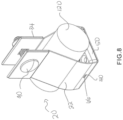
FIG. 8 is a perspective view of the cable cleat ofFIG. 3 securing a single cable. -
FIG. 2 illustrates acable cleat 20 with a clampingflange 30 having adouble hem 34 of the present invention. Thecable cleat 20 includes a one-piece metal shell 22. The formed one-piece shell 22 includes a bottom 24, twosides 26 extending from the bottom 24, and two clampingflanges 30 at thedistal end 28 of thesides 26. The one-piece shell 22 does not include a folded hem along the outer edges of the shell as described above with respect to prior art cable cleat shells. Instead, the one-piece metal shell 22 includes rounded edges 32. The rounded edge design of the present invention eliminates the need for a protective liner. As a result, the rounded edge shell reduces manufacturing costs by eliminating the protective liner as well as simplifying the manufacturing process by eliminating the need to install a protective liner. - The
cable cleat 20 of the present invention also does not include a hinge. A thinner gauge stainless steel material can be used for thecable cleat 20. The cable cleat manufactured from thinner gauge stainless steel can be manipulated with very little effort. As a result, thecable cleat 20 can be formed from a one-piece shell 22 thereby eliminating the need of a hinge as required in various prior art cable cleats. The elimination of the hinge reduces the scrap produced while creating the hinge and the need for tooling to form the hinge. - At the distal end of the sidewalls, the metal shell is folded over itself multiple times to form clamping
flanges 30 having adouble hem 34. The double hemmed 34clamping flanges 30 reinforce theshell 22 of thecable cleat 20. The double hemmed 34clamping flanges 30 also eliminate the need for shims to strengthen the clampingflanges 30. The clamping flange bolt holes 36 are punched after the metal is folded which facilitates in assembling thecable cleat 20. Welds could also be added to the double hemmed clampingflange 30 to increase the strength of the clampingflange 30, if desired. Additionally, an oversized washer (not illustrated) can be used, if desired, to distribute the clamping force over a larger area and greatly reduce the possibility of the bolt, washer, and nut from pulling through the clamping bolt holes 36. - The
cable cleat 20 includes one thruhole 38 at the bottom 24 of theshell 22 for mounting. The thruhole 38 will be sized for a 10 mm carriage bolt or other type of 10mm bolt. As discussed below, thecable cleat 20 also includes punchedholes 40 in thesides 26 of theshell 22 for receiving the attachment tabs 66 of aspacer 50. - Cable cleats are normally attached by a fastener directly to a ladder rung or by a bracket attached to the ladder rung. To avoid any damage, cable cleats holding a single or multi conductor cable should not come into contact with the head of the mounting fastener. A spacer is typically installed in the cable cleat to protect the cable from the head of the fastener during short circuit events and cable movement during expansion and contraction. The spacer also enables the cable cleat to receive a range of cable diameters.
- As illustrated in
FIG. 3 , thecable cleat 20 of the present invention includes aspacer 50.FIG. 4 illustrates a perspective view of thespacer 50. Thespacer 50 is rectangular with a top 52, a bottom 54, a front 56, a back 58, and two opposingsides 60. Thespacer 50 includes a center opening 62 extending from the top 52 to the bottom 54 for receiving the fastener used to secure thecable cleat 20 to a ladder rack or to a bracket. Thespacer 50 also includes a plurality ofribs 64 extending along the top 52. Theribs 64 reduce the axial movement of the cables installed in thecable cleat 20. Eachside 60 of thespacer 50 includes an attachment tab 66 extending outwardly away from thespacer 50 at the center of thespacer 50. As described below with respect toFIG. 5 , the top 52 of thespacer 50 includes twoadditional openings 68 for receiving interlockingconnectors 84 of an upper orsecond spacer 70. - Many heavy duty or thicker gauge cable cleats attach spacers to cable cleat via fasteners, such as small screws. However, in the
cable cleat 20 of the present invention, thecable cleat shell 22 is not thick enough to receive fasteners. As a result, the attachment tabs 66 extending from thespacer 50 of the present invention snap fit into the punchedholes 40 in thesides 26 of thecable cleat shell 22. The attachment tabs 66 enable thespacer 50 to be secured to thecable cleat 20 without the use of fasteners or any adhesives. - As illustrated in
FIG. 5 , thecable cleat 20 may also include an upper orsecond spacer 70, if desired. The addition of anupper spacer 70 increases the cable diameter range for thecable cleat 20. Theupper spacer 70 is rectangular with a top 72, a bottom 74, a front 76, a back 78, and two opposingsides 80. The top 72 of theupper spacer 70 includes a plurality ofribs 82 for increasing the axial force retention of thecable cleat 20.Interlocking connectors 84 extend from the bottom 74 of theupper spacer 70. The interlockingconnectors 84 align with and engage theopenings 68 in thespacer 50 enabling theupper spacer 70 to attach to thespacer 50 installed in thecable cleat 20. Thus, thespacer 50 and theupper spacer 70, if used, provides a cushion for the cable secured in thecable cleat 20 and protects the cable from the mounting bolt or other mounting hardware. -
FIGS. 6-8 illustrate the cable cleat of the present invention secured by afastener 90, such as a bolt and nut, holding cables in various configurations. As illustrated inFIG. 6 , the cable cleat may be used to install cables in atrefoil configuration 100. As illustrated inFIG. 7 , the cable cleat may be used to install cables in aquad configuration 110. As illustrated inFIG. 8 , the cable cleat may be used to install asingle cable 120. - The
cable cleat 20 of the present invention is manufactured by first placing a fully rounded edge coil in a controlled payout system. The end of the rounded edge coil is fed through a series of straighteners. The straighten strip is then precisely fed into a die for mounting holes, pilot holes, and spacer holes. The strip is then cut from the coil. A controlled shuttling device grips the punched strip using the mounting and pilot holes for precision positioning and movement during the manufacturing process. The controlled shuttle moves the punched strip into forming dies to fold the double hemmed clampingflanges 30. The clampingflanges 30 may be welded together, if desired. The clamping bolt holes 36 are punched thru the double hemmed folded clampingflanges 30. The semi formed cleat is then positioned in a series of dies for final shaping. Finally, the clamping flange hardware, such as a carriage bolt, retaining washer, washer, and nylon lock nut, is added to the cable cleat. - The
cable cleat 20 with the double hemmed clampingflanges 30 of the present invention provides many advantages. The double hemmedflange 30 created during the manufacturing process does not require reinforcements. The clampingflange bolt hole 36 is punched after the double hemmed clampingflange 30 is folded. Previous cable cleats are required to use pre-punched washers as rectangular shims to reinforce the clamping flange. - The
edges 32 of thecable cleat 20 are fully rounded to protect cable jackets from being damaged during short circuit events. The rounded edges 32 also eliminates the need of an extra hem or a liner to protect the cables. Thecable cleat 20 is manufactured from fully rounded edge strip material by folding or punching operations. Thecable cleat 20 is made of a thinner material for a more-cost effective cable cleat. - The
cable cleat 20 of the present invention does not include a hinge which reduces manufacturing costs by eliminating manufacturing steps, eliminates scrap created when a hinge barrel is formed, and eliminates the need of a hinge pin. - Furthermore, while the preferred embodiments of the present invention have been shown and described, it will be obvious to those skilled in the art that changes, and modifications may be made without departing from the teaching of the invention. The matter set forth in the foregoing description and accompanying drawings is offered by way of illustration only and not as limitation. The actual scope of the invention is intended to be defined in the following claims when viewed in their proper perspective based on the prior art.
Claims (11)
- A cable cleat assembly for securing cables during a short circuit event, the cable cleat assembly comprising:a one-piece metal shell having a bottom, sides extending from the bottom, and clamping flanges extending from the distal end of each side;wherein the clamping flanges are double hemmed clamping flanges for reinforcing the cable cleat assembly.
- The cable cleat assembly of claim 1, wherein the one-piece shell having rounded outer edges.
- The cable cleat assembly of any preceding claim, wherein each clamping flange has a hole for receiving a fastener to secure the cable cleat assembly.
- The cable cleat assembly of claim 3, wherein the holes in the clamping flange are punched after the shell is folded to form the double hem.
- The cable cleat assembly of any preceding claim, wherein the double hemmed flanges are welded for increasing the strength of the clamping flanges.
- The cable cleat assembly of any preceding claim, wherein each side of the one-piece shell having a punched hole.
- The cable cleat assembly of claim 6, further comprising a spacer having a top, a bottom, a front, a back and opposing sides, wherein each side having an attachment tab extending outwardly therefrom, wherein the attachment tabs are positioned within the punched holes in the sides of the one-piece shell to secure the spacer within the one-piece shell.
- The cable cleat of claim 7, wherein the spacer having a plurality of ribs extending along the top of the spacer for increasing axial retention of the cables.
- The cable cleat of claim 7, wherein the spacer having a center opening for receiving a fastener to secure the cable cleat assembly.
- The cable cleat assembly of claim 7, further comprising an upper spacer having a top, a bottom, a front, a back, and opposing sides, wherein ribs extend from the top of the upper spacer for increasing axial retention of the cables; and wherein interlocking connectors extend from the bottom of the upper spacer.
- The cable cleat assembly of claim 10, wherein the spacer having openings in the top, wherein the interlocking connectors of the upper spacer engage the opening in the top of the spacer to secure the upper spacer to the spacer.
Applications Claiming Priority (1)
| Application Number | Priority Date | Filing Date | Title |
|---|---|---|---|
| US17/708,643 US20230318273A1 (en) | 2022-03-30 | 2022-03-30 | Cable cleat with double hemmed clamping flange |
Publications (3)
| Publication Number | Publication Date |
|---|---|
| EP4254697A1 true EP4254697A1 (en) | 2023-10-04 |
| EP4254697C0 EP4254697C0 (en) | 2025-12-31 |
| EP4254697B1 EP4254697B1 (en) | 2025-12-31 |
Family
ID=85703764
Family Applications (1)
| Application Number | Title | Priority Date | Filing Date |
|---|---|---|---|
| EP23162269.7A Active EP4254697B1 (en) | 2022-03-30 | 2023-03-16 | Cable clamp with double-stitched clamping flange |
Country Status (4)
| Country | Link |
|---|---|
| US (1) | US20230318273A1 (en) |
| EP (1) | EP4254697B1 (en) |
| KR (1) | KR20230141475A (en) |
| CN (1) | CN220325157U (en) |
Families Citing this family (2)
| Publication number | Priority date | Publication date | Assignee | Title |
|---|---|---|---|---|
| US20230318273A1 (en) | 2022-03-30 | 2023-10-05 | Panduit Corp. | Cable cleat with double hemmed clamping flange |
| USD1061199S1 (en) * | 2022-10-02 | 2025-02-11 | Fiber Reaper, LLC | Cable clamp |
Citations (8)
| Publication number | Priority date | Publication date | Assignee | Title |
|---|---|---|---|---|
| US1830558A (en) * | 1931-05-18 | 1931-11-03 | Olson Bros Saw Mfg Co Inc | Clamp |
| US4078281A (en) | 1975-04-07 | 1978-03-14 | Pease James F | Hose clamp with tangential screw |
| US5116083A (en) * | 1988-08-04 | 1992-05-26 | Donaldson Company, Inc. | Clamp for coupling and sealing pipe joints |
| GB2361029A (en) | 2000-04-06 | 2001-10-10 | Walkern Victoria Ind Ltd | Clamps for cables, pipes |
| US20070241242A1 (en) | 2006-04-14 | 2007-10-18 | Kopp John G | Break-apart conduit bracket sheet |
| US20190234533A1 (en) * | 2018-01-26 | 2019-08-01 | Panduit Corp. | Cable Management Assembly |
| EP3835638A1 (en) * | 2019-12-10 | 2021-06-16 | Walter Stauffenberg Gmbh & Co. Kg | Device for the fixing of lines |
| US20230318273A1 (en) | 2022-03-30 | 2023-10-05 | Panduit Corp. | Cable cleat with double hemmed clamping flange |
Family Cites Families (13)
| Publication number | Priority date | Publication date | Assignee | Title |
|---|---|---|---|---|
| US1479317A (en) * | 1922-11-27 | 1924-01-01 | Ralph S Peirce | Pipe clamp |
| US2102900A (en) * | 1936-04-20 | 1937-12-21 | Milcor Steel Company | Resilient conductor fastening |
| NL147525B (en) * | 1969-06-28 | 1975-10-15 | Henning Wolfgang | CLAMP STRAP. |
| US3802654A (en) * | 1972-08-11 | 1974-04-09 | Ibm | Strain relief cable anchor |
| USRE33639E (en) * | 1979-05-08 | 1991-07-16 | Hans Oetiker Ag Maschinen- Und Apparatefabrik | Mechanical lock for clamps |
| US5310158A (en) * | 1990-07-22 | 1994-05-10 | Bks Company | Hanger clamp assembly |
| US5188319A (en) * | 1992-01-27 | 1993-02-23 | Navistar International Transportation Corp. | Clamp for hoses, tubing and/or electrical harnesses |
| US6269524B1 (en) * | 1998-06-11 | 2001-08-07 | Thomas R. Cassel | Band clamp |
| US7770848B2 (en) * | 2007-11-29 | 2010-08-10 | The Boeing Company | Clamp for securing an object to a structure |
| US8439317B2 (en) * | 2009-02-27 | 2013-05-14 | Franklin Fastener Company | Grommeted clamp assembly |
| US7837156B1 (en) * | 2009-10-19 | 2010-11-23 | Jordan Handler | Cable support hook |
| NL2016119B1 (en) * | 2016-01-19 | 2017-07-25 | Walraven Holding Bv J Van | Pipe hanger. |
| NL2017894B1 (en) * | 2016-11-30 | 2018-06-11 | Walraven Holding Bv J Van | Pipe hanger |
-
2022
- 2022-03-30 US US17/708,643 patent/US20230318273A1/en not_active Abandoned
-
2023
- 2023-03-08 KR KR1020230030592A patent/KR20230141475A/en active Pending
- 2023-03-16 EP EP23162269.7A patent/EP4254697B1/en active Active
- 2023-03-27 CN CN202320636743.2U patent/CN220325157U/en active Active
Patent Citations (8)
| Publication number | Priority date | Publication date | Assignee | Title |
|---|---|---|---|---|
| US1830558A (en) * | 1931-05-18 | 1931-11-03 | Olson Bros Saw Mfg Co Inc | Clamp |
| US4078281A (en) | 1975-04-07 | 1978-03-14 | Pease James F | Hose clamp with tangential screw |
| US5116083A (en) * | 1988-08-04 | 1992-05-26 | Donaldson Company, Inc. | Clamp for coupling and sealing pipe joints |
| GB2361029A (en) | 2000-04-06 | 2001-10-10 | Walkern Victoria Ind Ltd | Clamps for cables, pipes |
| US20070241242A1 (en) | 2006-04-14 | 2007-10-18 | Kopp John G | Break-apart conduit bracket sheet |
| US20190234533A1 (en) * | 2018-01-26 | 2019-08-01 | Panduit Corp. | Cable Management Assembly |
| EP3835638A1 (en) * | 2019-12-10 | 2021-06-16 | Walter Stauffenberg Gmbh & Co. Kg | Device for the fixing of lines |
| US20230318273A1 (en) | 2022-03-30 | 2023-10-05 | Panduit Corp. | Cable cleat with double hemmed clamping flange |
Non-Patent Citations (2)
| Title |
|---|
| THORNE & DERRICK: "Ellis Patents Cable Cleats - Vulcan Cable Cleat VRT 04 (Stainless Steel Cable Cleats)", 17 November 2013 (2013-11-17), XP093072389, Retrieved from the Internet <URL:https://www.youtube.com/watch?v=ZtLhwkpDSg4> [retrieved on 20230809] * |
| UNKNOWN: "PTS ProTect Short-Circuit Cable Straps", HTTPS://WWW.ETSCABLECOMPONENTS.COM/, 21 June 2021 (2021-06-21), pages 1 - 3, XP093072379, Retrieved from the Internet <URL:http://web.archive.org/web/20210621034807/https://www.etscablecomponents.com/product/pts-protect-short-circuit-cable-straps-protect/> [retrieved on 20230809] * |
Also Published As
| Publication number | Publication date |
|---|---|
| KR20230141475A (en) | 2023-10-10 |
| US20230318273A1 (en) | 2023-10-05 |
| EP4254697C0 (en) | 2025-12-31 |
| EP4254697B1 (en) | 2025-12-31 |
| CN220325157U (en) | 2024-01-09 |
Similar Documents
| Publication | Publication Date | Title |
|---|---|---|
| EP4254697B1 (en) | Cable clamp with double-stitched clamping flange | |
| EP0268302B1 (en) | Fastener and method of attachment to sheet material | |
| EP1545823B1 (en) | Split weld cage nut assembly | |
| US8991901B2 (en) | Energy absorber device for a vehicle and method of manufacturing same | |
| DE10297288B4 (en) | Tab for adjusting the Z-height of an airbag module | |
| DE102021211538A1 (en) | Multi-part battery module wall | |
| CN107017480B (en) | Battery terminal | |
| EP2465717B1 (en) | Method for producing an inner door sheet with a bearing section and a door module holder | |
| US6616204B1 (en) | Adjustable mounting plate | |
| EP3796414B1 (en) | Battery module | |
| EP1452404B1 (en) | Airbag for steering wheel | |
| EP4371828A1 (en) | Crash box | |
| US11034219B2 (en) | Vehicle doors including torsion bar support assemblies and methods for assembling the same | |
| JPS63270223A (en) | Installation of door impact beam | |
| US9021703B2 (en) | Method of manufacturing a roof bow | |
| DE102023112056A1 (en) | Fuel cell unit and assembly method therefor | |
| DE102017201763B4 (en) | Protective element for a wiring harness | |
| US20180105121A1 (en) | Vehicle trim portion connection bracket | |
| US20260042361A1 (en) | Self-location features for component assembly | |
| US20250206241A1 (en) | Attachment structure of electrical component and manufacturing method of attachment structure | |
| JP3194144B2 (en) | Arrangement structure of rear parcel side | |
| JPH11185842A (en) | Laminated fixing structure of plate-like members | |
| CN220510722U (en) | Bus duct and stamping die | |
| CN214117830U (en) | Mounting structure and vehicle of door hasp | |
| CN112744298A (en) | B-pillar inner plate and vehicle with same |
Legal Events
| Date | Code | Title | Description |
|---|---|---|---|
| PUAI | Public reference made under article 153(3) epc to a published international application that has entered the european phase |
Free format text: ORIGINAL CODE: 0009012 |
|
| STAA | Information on the status of an ep patent application or granted ep patent |
Free format text: STATUS: THE APPLICATION HAS BEEN PUBLISHED |
|
| AK | Designated contracting states |
Kind code of ref document: A1 Designated state(s): AL AT BE BG CH CY CZ DE DK EE ES FI FR GB GR HR HU IE IS IT LI LT LU LV MC ME MK MT NL NO PL PT RO RS SE SI SK SM TR |
|
| STAA | Information on the status of an ep patent application or granted ep patent |
Free format text: STATUS: REQUEST FOR EXAMINATION WAS MADE |
|
| 17P | Request for examination filed |
Effective date: 20240104 |
|
| RBV | Designated contracting states (corrected) |
Designated state(s): AL AT BE BG CH CY CZ DE DK EE ES FI FR GB GR HR HU IE IS IT LI LT LU LV MC ME MK MT NL NO PL PT RO RS SE SI SK SM TR |
|
| TPAC | Observations filed by third parties |
Free format text: ORIGINAL CODE: EPIDOSNTIPA |
|
| GRAP | Despatch of communication of intention to grant a patent |
Free format text: ORIGINAL CODE: EPIDOSNIGR1 |
|
| STAA | Information on the status of an ep patent application or granted ep patent |
Free format text: STATUS: GRANT OF PATENT IS INTENDED |
|
| INTG | Intention to grant announced |
Effective date: 20250919 |
|
| GRAS | Grant fee paid |
Free format text: ORIGINAL CODE: EPIDOSNIGR3 |
|
| GRAA | (expected) grant |
Free format text: ORIGINAL CODE: 0009210 |
|
| STAA | Information on the status of an ep patent application or granted ep patent |
Free format text: STATUS: THE PATENT HAS BEEN GRANTED |
|
| AK | Designated contracting states |
Kind code of ref document: B1 Designated state(s): AL AT BE BG CH CY CZ DE DK EE ES FI FR GB GR HR HU IE IS IT LI LT LU LV MC ME MK MT NL NO PL PT RO RS SE SI SK SM TR |
|
| REG | Reference to a national code |
Ref country code: CH Ref legal event code: F10 Free format text: ST27 STATUS EVENT CODE: U-0-0-F10-F00 (AS PROVIDED BY THE NATIONAL OFFICE) Effective date: 20251231 Ref country code: GB Ref legal event code: FG4D |
|
| REG | Reference to a national code |
Ref country code: DE Ref legal event code: R096 Ref document number: 602023010240 Country of ref document: DE |
|
| REG | Reference to a national code |
Ref country code: IE Ref legal event code: FG4D |
|
| U01 | Request for unitary effect filed |
Effective date: 20260107 |
|
| U07 | Unitary effect registered |
Designated state(s): AT BE BG DE DK EE FI FR IT LT LU LV MT NL PT RO SE SI Effective date: 20260113 |
|
| PG25 | Lapsed in a contracting state [announced via postgrant information from national office to epo] |
Ref country code: NO Free format text: LAPSE BECAUSE OF FAILURE TO SUBMIT A TRANSLATION OF THE DESCRIPTION OR TO PAY THE FEE WITHIN THE PRESCRIBED TIME-LIMIT Effective date: 20260331 |
|
| PG25 | Lapsed in a contracting state [announced via postgrant information from national office to epo] |
Ref country code: HR Free format text: LAPSE BECAUSE OF FAILURE TO SUBMIT A TRANSLATION OF THE DESCRIPTION OR TO PAY THE FEE WITHIN THE PRESCRIBED TIME-LIMIT Effective date: 20251231 |
|
| PG25 | Lapsed in a contracting state [announced via postgrant information from national office to epo] |
Ref country code: RS Free format text: LAPSE BECAUSE OF FAILURE TO SUBMIT A TRANSLATION OF THE DESCRIPTION OR TO PAY THE FEE WITHIN THE PRESCRIBED TIME-LIMIT Effective date: 20260331 |
|
| U20 | Renewal fee for the european patent with unitary effect paid |
Year of fee payment: 4 Effective date: 20260327 |