EP4254680A1 - Shielded connection assembly, connector for this connection assembly and method of manufacturing a shielding element for this connection assembly - Google Patents
Shielded connection assembly, connector for this connection assembly and method of manufacturing a shielding element for this connection assembly Download PDFInfo
- Publication number
- EP4254680A1 EP4254680A1 EP22215721.6A EP22215721A EP4254680A1 EP 4254680 A1 EP4254680 A1 EP 4254680A1 EP 22215721 A EP22215721 A EP 22215721A EP 4254680 A1 EP4254680 A1 EP 4254680A1
- Authority
- EP
- European Patent Office
- Prior art keywords
- contact
- shielding element
- connector
- tab
- contact tab
- Prior art date
- Legal status (The legal status is an assumption and is not a legal conclusion. Google has not performed a legal analysis and makes no representation as to the accuracy of the status listed.)
- Granted
Links
Images


Classifications
-
- H—ELECTRICITY
- H01—ELECTRIC ELEMENTS
- H01R—ELECTRICALLY-CONDUCTIVE CONNECTIONS; STRUCTURAL ASSOCIATIONS OF A PLURALITY OF MUTUALLY-INSULATED ELECTRICAL CONNECTING ELEMENTS; COUPLING DEVICES; CURRENT COLLECTORS
- H01R13/00—Details of coupling devices of the kinds covered by groups H01R12/70 or H01R24/00 - H01R33/00
- H01R13/648—Protective earth or shield arrangements on coupling devices, e.g. anti-static shielding
- H01R13/658—High frequency shielding arrangements, e.g. against EMI [Electro-Magnetic Interference] or EMP [Electro-Magnetic Pulse]
- H01R13/6581—Shield structure
- H01R13/6582—Shield structure with resilient means for engaging mating connector
-
- H—ELECTRICITY
- H01—ELECTRIC ELEMENTS
- H01R—ELECTRICALLY-CONDUCTIVE CONNECTIONS; STRUCTURAL ASSOCIATIONS OF A PLURALITY OF MUTUALLY-INSULATED ELECTRICAL CONNECTING ELEMENTS; COUPLING DEVICES; CURRENT COLLECTORS
- H01R43/00—Apparatus or processes specially adapted for manufacturing, assembling, maintaining, or repairing of line connectors or current collectors or for joining electric conductors
- H01R43/16—Apparatus or processes specially adapted for manufacturing, assembling, maintaining, or repairing of line connectors or current collectors or for joining electric conductors for manufacturing contact members, e.g. by punching and by bending
-
- H—ELECTRICITY
- H01—ELECTRIC ELEMENTS
- H01R—ELECTRICALLY-CONDUCTIVE CONNECTIONS; STRUCTURAL ASSOCIATIONS OF A PLURALITY OF MUTUALLY-INSULATED ELECTRICAL CONNECTING ELEMENTS; COUPLING DEVICES; CURRENT COLLECTORS
- H01R2103/00—Two poles
-
- H—ELECTRICITY
- H01—ELECTRIC ELEMENTS
- H01R—ELECTRICALLY-CONDUCTIVE CONNECTIONS; STRUCTURAL ASSOCIATIONS OF A PLURALITY OF MUTUALLY-INSULATED ELECTRICAL CONNECTING ELEMENTS; COUPLING DEVICES; CURRENT COLLECTORS
- H01R2201/00—Connectors or connections adapted for particular applications
- H01R2201/26—Connectors or connections adapted for particular applications for vehicles
Definitions
- the invention relates to the field of connectors for motor vehicles and in particular to the field of connectors shielded against electromagnetic interference.
- electrical connection assemblies comprising a shielded connector and counter-connector.
- Each one of these connector and counter-connector comprises a housing in which at least one electrical contact and at least one shielding element are housed.
- the shielding elements are configured to reduce the influence on the environment of potential electromagnetic disturbances generated by these high currents.
- electrical continuity is sought between the shielding of the connector and the shielding of the counter-connector.
- contact tabs are then provided on at least one of the shielding elements of the connector, these contact tabs being configured to establish a connection with a shielding element of the counter connector.
- Each of these contact tabs is in the form of a deformable lamella and comprises a junction portion and a contact portion.
- the contact tab is connected to the body of the shielding element only via the junction portion and is shaped so that the contact portion projects from a surface of the body.
- This type of contact tabs can cause the shielding of one connector to be incorrectly connected to the shielding of the other connector. For example, it may happen that the contact tabs are deformed during storage between the manufacture of the shielding element comprising these contact tabs and the assembly of this shielding element in a connector. Furthermore, these contact tabs are often very flexible and do not necessarily provide sufficient contact force.
- a shielded connection assembly, a connector and a method of manufacturing a shielding element for this connection assembly are described below, which contribute at least partially to overcome at least one of the aforementioned drawbacks.
- an electrical connection assembly for a motor vehicle electrical circuit comprising a connector and a counter-connector.
- the connector comprises at least one first shielding element and the counter-connector comprises at least one second shielding element.
- the first shielding element comprises a body formed from a metal sheet from which at least one resilient contact tab is cut out. This contact tab or tongue extends along a longitudinal direction. It comprises at least one junction portion and a contact portion projecting from a surface of the body. This contact tab is connected to the body only by the junction portion. It is configured to make electrical contact with the second shielding element, when the connector is mated with the counter connector.
- each contact tab comprises an interference portion which is connected to the remainder of the body only via a longitudinal segment, which is itself connected to the body only via the junction portion.
- each contact tab is configured so that its interference portion abuts the body of the first shielding element when the connector is mated with the counter connector.
- each contact tab is integral with the body of the first shielding element. It is therefore rigidly connected to the body via the junction portion located at one of its longitudinal ends. But the other longitudinal end is free.
- an interference portion is provided on the contact tab and this interference portion can come to bear on the body so that the movement of the free end is limited.
- pressure on the contact portion pushes the interference portion against the body. This limits the deformation of the contact tabs and allows a greater contact force to be maintained than in prior art connection assemblies in which one end of the contact tab is free. Thus this allows for better electrical contact, between the contact tab of the first shielding element and the second shielding element.
- connection assembly also optionally comprises one and/or other of the following features, each considered independently of the other or in combination with one or more others:
- a connector comprising a housing, a terminal and at least a first shielding element housed in the housing.
- the first shielding element comprises a body formed of a sheet metal from which at least one resilient contact tab is cut out which extends along a longitudinal direction.
- the contact tab comprises at least one junction portion and one contact portion. The contact tab is connected to the body only via the junction portion and is curved, bent, in such a way that the contact portion protrudes from a surface of the body.
- Each contact tab further comprises an interference portion configured to be able to interfere with the body of the first shielding element.
- the body of the first shielding element comprises an opening arranged under the contact tab, this opening being bordered by two support zones spaced apart, perpendicularly to the longitudinal direction, by a maximum distance which is less than the largest dimension, perpendicularly to the longitudinal direction, of the interference portion.
- This method comprises
- connection assembly 1 An example of an embodiment of a connection assembly 1 is shown in Figures 1 and 2 .
- This connection assembly 1 is used, for example, in an electrical power circuit of a motor vehicle.
- Such a circuit is used, for example, to interconnect components such as a battery, a charging station, a converter, an electric motor, etc.
- This connection assembly 1 comprises a connector 2 and a counter-connector 3.
- both the connector 2 and the counter connector 3 comprise a housing 30 with two cavities in each of which a power terminal 4, 5 is housed.
- the connector 2 and the counter connector 3 are two-way power connectors.
- each connecting channel (way) is individually shielded.
- two female terminals 4 are accommodated in the connector 2 and two male terminals 5 are accommodated in the counter connector 3.
- Each power terminal 4, 5 is attached and electrically connected to a cable 29 comprising a shielding braid.
- each of the shielding braids is electrically connected to a separate shielding element 6, 7.
- the connector 2 has two first shielding elements 6 and the counter connector 3 has two second shielding elements 7.
- the first 6 and second 7 shielding elements have a generally cylindrical shape with a circular base. They extend longitudinally parallel to a central longitudinal axis A (see Figures 3, 4 and 6 ).
- each first shielding element 6 comprises a body 8 formed from a sheet of metal from which resilient contact tabs 9 are cut out.
- Each first shielding element 6 thus comprises a plurality of contact tabs 9. For example, there are eight of these contact tabs 9. These contact tabs 9 are distributed in pairs symmetrically with respect to the central axis A (see figure 6 ). Thus, the contact force exerted by each of the contact tabs 9 of a first shielding element 6 on a second shielding element 7 is better distributed and balanced as well as more uniform.
- each contact tab 9 extends along a longitudinal direction parallel to the central axis A.
- each contact tab 9 has a "T" shape and comprises a longitudinal segment 10 and a transverse segment 11.
- the longitudinal segment 10 extends between a junction portion 12 and the transverse segment 11.
- the longitudinal segment 10 comprises a contact portion 13 and the transverse segment 11 comprises an interference portion 14.
- Each contact tab 9 is oriented from the junction area 12 to the interference portion 14 in a direction corresponding to the direction of mating of the connector 2 with the counter connector 3.
- Each contact tab 9 is connected to the body 8 only by the junction portion 12. In other words, each contact tab 9 is cut out from the body 8 along a cutting line which runs all the way around the contact tab 9 (including the transverse segment 11) except at the junction area 12 where the cutting line is interrupted. Each contact tab 9 is thus released from the body 8, except at the junction area 12.
- each contact tab 9 is bent so as to lift the contact portion 13 from the outer surface 15 of the body 8.
- the contact portion 13 thus protrudes from the outer surface 15 of the body 8.
- the longitudinal segment 10 has two substantially parallel longitudinal edges, between which the distance defines the width d of the longitudinal segment 10.
- the transverse segment 11 extends perpendicular to the longitudinal segment 10 at a free end of the contact tab 9 longitudinally opposite the junction portion 12.
- the transverse segment 11 has a length L greater than the width l of the longitudinal segment 10.
- the transverse segment 11 has two interference tabs 16.
- Each interference tab 16 is configured to rest on the body 8 on either side of an opening 17 in the body 8, which is located substantially below the contact tab 9, when the contact portion 13 makes an electrical contact with the second shielding element 7.
- this opening 17 is bordered by two support zones 18, each of the interference tabs 16 being brought into superposition of a respective support zones 18.
- the first shielding element 6 supports a retention ring 20.
- the retention ring 20 comprises a substantially cylindrical wall 25 extending longitudinally parallel to the central axis A, between a first 21 and a second 22 circular edge.
- Protrusions 23 are provided in the vicinity of the first edge 21. These protrusions 23 are configured to retain the retention ring 20 on the first shielding member 6 and to orient the retention ring 20 and the first shielding member 6 relative to each other.
- the second edge 22 comprises a flange 24 the diameter of which is larger than the cylinder forming the wall 25.
- the cylindrical wall 25 has windows 26, each configured and positioned for the passage of the contact portion 13 of a respective contact tab 9.
- a method for manufacturing a first shielding element 6 as described below comprises one or more cutting operations and several forming operations. For example, it comprises an operation of cutting, from a metal sheet, a shape corresponding essentially to the flat shape of the first shielding element 6. This cutting operation thus includes cutting out the body 8 of the first shielding element 6. The contact tabs 9 are then cut out from the body 8. The body 8 also has longitudinal edges 27 cut out in a mortise and tenon shape. After this operation, each contact tab 9 extends flat along a longitudinal direction.
- a first forming operation by bending the longitudinal segment 10, is therefore carried out to raise the contact portion 13 of each longitudinal segment 10 with respect to the body 8 and to bring the interference portion 14 into alignment and superposition with the support zones 18.
- This first forming operation results in openings 17, each of which is arranged under a contact portion 9 and bordered by two support zones 18. This also results in open areas 28, each corresponding to an opening resulting from the cut out of the transverse segment 11 of each contact portion 9.
- the first forming operation is followed by a second forming operation consisting of bending the body 8 about the central longitudinal axis A and bringing the longitudinal edges 27 into engagement with each other.
- the interference portion 14 (of each contact tab 9) is in register with a support zone 18, on the outer surface 15 of the first shielding element 6.
- the first shielding element 6 is at least partially inserted into the second shielding element 7.
- the contact portion 13 engages under the second shielding element 7.
- the bending of the unstressed contact tab 9 is such that the height of the contact tab 9 below the contact portion 13 is greater than the space E between the first 6 and second 7 shielding elements.
- first 6 and second 7 shielding elements are configured in such a way that, when the connector 2 and the counter-connector 3 are mated, the openings 17 and open areas 28 of one are covered by a solid area of the other. In this way, the shielding performance is optimised.
- the contact tabs 9 have been described above, in particular with regard to the transverse segment 11, the support zones 18, the open areas 28, etc., but other shapes can be envisaged.
- the transverse segment 11 is not located at the free end of the contact tab 9, but at another distance from the junction portion along the longitudinal segment 10.
- the interference portion 14 may have a rounded shape, etc.
- the shielding elements 6, 7 may have cross-sections other than circular
- each shielding element 6 or 7 may be common to several tracks
- each first shielding element 6 may comprise at least one flat zone at which one or more contact tabs 9 are located, etc.
Landscapes
- Engineering & Computer Science (AREA)
- Manufacturing & Machinery (AREA)
- Manufacturing Of Electrical Connectors (AREA)
- Details Of Connecting Devices For Male And Female Coupling (AREA)
Abstract
Description
- The invention relates to the field of connectors for motor vehicles and in particular to the field of connectors shielded against electromagnetic interference.
- There are electrical connection assemblies comprising a shielded connector and counter-connector. Each one of these connector and counter-connector comprises a housing in which at least one electrical contact and at least one shielding element are housed. In the case of electrical connection assemblies configured to transmit high currents (for example in electric, hybrid or plug-in hybrid vehicles) the shielding elements are configured to reduce the influence on the environment of potential electromagnetic disturbances generated by these high currents. To this end, electrical continuity is sought between the shielding of the connector and the shielding of the counter-connector. As described in
EP3107155A1 contact tabs are then provided on at least one of the shielding elements of the connector, these contact tabs being configured to establish a connection with a shielding element of the counter connector. Each of these contact tabs is in the form of a deformable lamella and comprises a junction portion and a contact portion. The contact tab is connected to the body of the shielding element only via the junction portion and is shaped so that the contact portion projects from a surface of the body. - This type of contact tabs can cause the shielding of one connector to be incorrectly connected to the shielding of the other connector. For example, it may happen that the contact tabs are deformed during storage between the manufacture of the shielding element comprising these contact tabs and the assembly of this shielding element in a connector. Furthermore, these contact tabs are often very flexible and do not necessarily provide sufficient contact force.
- A shielded connection assembly, a connector and a method of manufacturing a shielding element for this connection assembly are described below, which contribute at least partially to overcome at least one of the aforementioned drawbacks.
- Thus, an electrical connection assembly for a motor vehicle electrical circuit is described, comprising a connector and a counter-connector. The connector comprises at least one first shielding element and the counter-connector comprises at least one second shielding element. The first shielding element comprises a body formed from a metal sheet from which at least one resilient contact tab is cut out. This contact tab or tongue extends along a longitudinal direction. It comprises at least one junction portion and a contact portion projecting from a surface of the body. This contact tab is connected to the body only by the junction portion. It is configured to make electrical contact with the second shielding element, when the connector is mated with the counter connector.
- In this connection assembly, each contact tab comprises an interference portion which is connected to the remainder of the body only via a longitudinal segment, which is itself connected to the body only via the junction portion. In addition, each contact tab is configured so that its interference portion abuts the body of the first shielding element when the connector is mated with the counter connector.
- In other words, each contact tab is integral with the body of the first shielding element. It is therefore rigidly connected to the body via the junction portion located at one of its longitudinal ends. But the other longitudinal end is free. However, an interference portion is provided on the contact tab and this interference portion can come to bear on the body so that the movement of the free end is limited. Thus, pressure on the contact portion pushes the interference portion against the body. This limits the deformation of the contact tabs and allows a greater contact force to be maintained than in prior art connection assemblies in which one end of the contact tab is free. Thus this allows for better electrical contact, between the contact tab of the first shielding element and the second shielding element.
- This connection assembly also optionally comprises one and/or other of the following features, each considered independently of the other or in combination with one or more others:
- the body of the first shielding element comprises an opening arranged under the contact tab, this opening being bordered by two support zones spaced apart, perpendicularly to the longitudinal direction, by a maximum distance which is less than the largest dimension, perpendicularly to the longitudinal direction, of the interference portion;
- the interference portion is formed by a transverse segment extending substantially transversely to the longitudinal segment, this transverse segment comprising two interference tabs; each interference tab rests on the body on either side of an opening in the body and located substantially under the contact tab, when the contact portion makes electrical contact with the second shielding element;
- the first and second shielding elements have a generally cylindrical shape with a circular base,
- the first shielding element has a central longitudinal axis and comprises a plurality of contact tabs distributed in pairs symmetrically with respect to the central axis;
- each tab is oriented from the junction portion to the interference portion, in a direction corresponding to that of coupling the connector with the counter-connector;
- the body of the first shielding element comprises an open area corresponding to an opening released by the transverse segment of each tab, after cutting of the latter and shaping of the contact portion, this open area being covered by the second shielding element when the connector is mated with the counter-connector.
- Also described below is a connector comprising a housing, a terminal and at least a first shielding element housed in the housing. The first shielding element comprises a body formed of a sheet metal from which at least one resilient contact tab is cut out which extends along a longitudinal direction. The contact tab comprises at least one junction portion and one contact portion. The contact tab is connected to the body only via the junction portion and is curved, bent, in such a way that the contact portion protrudes from a surface of the body.
- Each contact tab further comprises an interference portion configured to be able to interfere with the body of the first shielding element.
- Optionally, in this connector, the body of the first shielding element comprises an opening arranged under the contact tab, this opening being bordered by two support zones spaced apart, perpendicularly to the longitudinal direction, by a maximum distance which is less than the largest dimension, perpendicularly to the longitudinal direction, of the interference portion.
- Also described below is a method of manufacturing a shielding element for a connection assembly. This method comprises
- a cutting operation in a metal sheet of a shape substantially corresponding to the flat shape of a first shielding element, this cutting operation comprising cutting the body of the first shielding element and at least one contact tab in this body, this contact tab extending along a longitudinal direction and comprising a junction portion, a contact portion and an interference portion,
- a first forming operation comprising a bending of the longitudinal segment, to raise the contact portion of the longitudinal segment relative to the body, the cutting of the contact tab and the bending leaving an opening in the body of the first shielding element disposed below the contact tab, this opening being bordered by two support zones, the interference portion also being brought into superposition of the support zones during the first forming operation, and
- a second forming operation consisting of bending the body about a longitudinal axis substantially parallel to the longitudinal segment.
- Further features and advantages will become apparent in the detailed discussion of various embodiments of the invention, the discussion being accompanied by examples and references to the accompanying drawings.
-
Figure 1 shows a schematic perspective of an example of a connection assembly, comprising a connector and a counter-connector; -
Figure 2 shows a schematic perspective and exploded view of the connection assembly shown inFigure 1 ; -
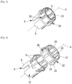
Figure 3 shows a schematic view of a shielding element for a connector of the connection assembly ofFigure 1 , on which a retention ring is mounted; -
Figure 4 shows the shielding element and the retention ring shown inFigure 3 schematically in perspective and in exploded view; -
Figure 5 shows a schematic view of a shielding element such as the one shown inFigures 3 and 4 in side elevation; -
Figure 6 shows a schematic view of the shielding element inFigure 5 ; -
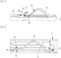
Figure 7 shows a schematic cross-section of a connecting tab of the shielding element ofFigure 5 ; and -
Figure 8 shows a schematic cross-section of a connecting tab of the shielding element offigure 5 in electrical contact with a shielding element of a counter-connector. - An example of an embodiment of a connection assembly 1 is shown in
Figures 1 and 2 . This connection assembly 1 is used, for example, in an electrical power circuit of a motor vehicle. Such a circuit is used, for example, to interconnect components such as a battery, a charging station, a converter, an electric motor, etc. - This connection assembly 1 comprises a
connector 2 and acounter-connector 3. For example, both theconnector 2 and thecounter connector 3 comprise ahousing 30 with two cavities in each of which apower terminal connector 2 and thecounter connector 3 are two-way power connectors. In the example shown inFigures 1 and 2 , each connecting channel (way) is individually shielded. For example, twofemale terminals 4 are accommodated in theconnector 2 and twomale terminals 5 are accommodated in thecounter connector 3. Eachpower terminal cable 29 comprising a shielding braid. Within theconnector 2 and thecounter connector 3 each of the shielding braids is electrically connected to aseparate shielding element connector 2 has twofirst shielding elements 6 and thecounter connector 3 has twosecond shielding elements 7. The first 6 and second 7 shielding elements have a generally cylindrical shape with a circular base. They extend longitudinally parallel to a central longitudinal axis A (seeFigures 3, 4 and6 ). - As shown more particularly in
Figures 3 to 6 , eachfirst shielding element 6 comprises abody 8 formed from a sheet of metal from whichresilient contact tabs 9 are cut out. Eachfirst shielding element 6 thus comprises a plurality ofcontact tabs 9. For example, there are eight of thesecontact tabs 9. Thesecontact tabs 9 are distributed in pairs symmetrically with respect to the central axis A (seefigure 6 ). Thus, the contact force exerted by each of thecontact tabs 9 of afirst shielding element 6 on asecond shielding element 7 is better distributed and balanced as well as more uniform. - Each of these
contact tabs 9 extends along a longitudinal direction parallel to the central axis A. In the embodiment example described herein, eachcontact tab 9 has a "T" shape and comprises alongitudinal segment 10 and atransverse segment 11. For example, thelongitudinal segment 10 extends between ajunction portion 12 and thetransverse segment 11. For example, thelongitudinal segment 10 comprises acontact portion 13 and thetransverse segment 11 comprises aninterference portion 14. Eachcontact tab 9 is oriented from thejunction area 12 to theinterference portion 14 in a direction corresponding to the direction of mating of theconnector 2 with thecounter connector 3. - Each
contact tab 9 is connected to thebody 8 only by thejunction portion 12. In other words, eachcontact tab 9 is cut out from thebody 8 along a cutting line which runs all the way around the contact tab 9 (including the transverse segment 11) except at thejunction area 12 where the cutting line is interrupted. Eachcontact tab 9 is thus released from thebody 8, except at thejunction area 12. - The
longitudinal segment 10 of eachcontact tab 9 is bent so as to lift thecontact portion 13 from theouter surface 15 of thebody 8. Thecontact portion 13 thus protrudes from theouter surface 15 of thebody 8. Thelongitudinal segment 10 has two substantially parallel longitudinal edges, between which the distance defines the width d of thelongitudinal segment 10. - The
transverse segment 11 extends perpendicular to thelongitudinal segment 10 at a free end of thecontact tab 9 longitudinally opposite thejunction portion 12. - The
transverse segment 11 has a length L greater than the width l of thelongitudinal segment 10. Thetransverse segment 11 has twointerference tabs 16. Eachinterference tab 16 is configured to rest on thebody 8 on either side of anopening 17 in thebody 8, which is located substantially below thecontact tab 9, when thecontact portion 13 makes an electrical contact with thesecond shielding element 7. In other words, thisopening 17 is bordered by twosupport zones 18, each of theinterference tabs 16 being brought into superposition of arespective support zones 18. - Furthermore, the
first shielding element 6 supports aretention ring 20. Theretention ring 20 comprises a substantiallycylindrical wall 25 extending longitudinally parallel to the central axis A, between a first 21 and a second 22 circular edge.Protrusions 23 are provided in the vicinity of thefirst edge 21. Theseprotrusions 23 are configured to retain theretention ring 20 on thefirst shielding member 6 and to orient theretention ring 20 and thefirst shielding member 6 relative to each other. Thesecond edge 22 comprises aflange 24 the diameter of which is larger than the cylinder forming thewall 25. Thecylindrical wall 25 haswindows 26, each configured and positioned for the passage of thecontact portion 13 of arespective contact tab 9. - According to an embodiment example, a method for manufacturing a
first shielding element 6 as described below comprises one or more cutting operations and several forming operations. For example, it comprises an operation of cutting, from a metal sheet, a shape corresponding essentially to the flat shape of thefirst shielding element 6. This cutting operation thus includes cutting out thebody 8 of thefirst shielding element 6. Thecontact tabs 9 are then cut out from thebody 8. Thebody 8 also haslongitudinal edges 27 cut out in a mortise and tenon shape. After this operation, eachcontact tab 9 extends flat along a longitudinal direction. - A first forming operation, by bending the
longitudinal segment 10, is therefore carried out to raise thecontact portion 13 of eachlongitudinal segment 10 with respect to thebody 8 and to bring theinterference portion 14 into alignment and superposition with thesupport zones 18. This first forming operation results inopenings 17, each of which is arranged under acontact portion 9 and bordered by twosupport zones 18. This also results inopen areas 28, each corresponding to an opening resulting from the cut out of thetransverse segment 11 of eachcontact portion 9. The first forming operation is followed by a second forming operation consisting of bending thebody 8 about the central longitudinal axis A and bringing thelongitudinal edges 27 into engagement with each other. - As shown in
figure 7 , after cutting and shaping operations, the interference portion 14 (of each contact tab 9) is in register with asupport zone 18, on theouter surface 15 of thefirst shielding element 6. Thus, as shown infigure 8 , when theconnector 2 is coupled to thecounter-connector 3, thefirst shielding element 6 is at least partially inserted into thesecond shielding element 7. Thecontact portion 13 engages under thesecond shielding element 7. The bending of theunstressed contact tab 9 is such that the height of thecontact tab 9 below thecontact portion 13 is greater than the space E between the first 6 and second 7 shielding elements. When theconnector 2 and thecounter connector 3 are mated, thecontact portion 13 is therefore pushed towards theouter surface 15 of thebody 8 of thefirst shielding element 6 and thecontact tab 9 is flattened. This causes theinterference portion 14 to interact with thesupport zone 18 via theinterference tabs 16. However, this interaction of theinterference portion 14 with thesupport zone 18 limits the deformation of thecontact tab 9, which then exerts a greater contact force, by thecontact portion 13, on thesecond shielding element 7. - Furthermore, the first 6 and second 7 shielding elements are configured in such a way that, when the
connector 2 and the counter-connector 3 are mated, theopenings 17 andopen areas 28 of one are covered by a solid area of the other. In this way, the shielding performance is optimised. - Particular shapes and positions for the
contact tabs 9 have been described above, in particular with regard to thetransverse segment 11, thesupport zones 18, theopen areas 28, etc., but other shapes can be envisaged. For example, according to variants, thetransverse segment 11 is not located at the free end of thecontact tab 9, but at another distance from the junction portion along thelongitudinal segment 10. According to other variants, theinterference portion 14 may have a rounded shape, etc., theshielding elements element first shielding element 6 may comprise at least one flat zone at which one ormore contact tabs 9 are located, etc.
Claims (8)
- Electrical connection assembly (1) for a motor vehicle electrical circuit, comprising a connector (2) and a counter-connector (3), the connector (2) comprising at least one first shielding element (6) and the counter-connector (3) comprising at least one second shielding element (7), the first shielding element (6) comprising a body (8) formed from a sheet metal from which at least one resilient contact tab (9) is cut out, extends along a longitudinal direction and comprises at least one junction portion (12) and one contact portion (13) protruding from a surface of the body (8) and configured to establish an electrical contact with the second shielding element (7), when the connector (2) is coupled to the counter connector (3),wherein each contact tab (9) comprises an interference portion (14) which is connected to the remainder of the body (8) only via a longitudinal segment (10) which is itself connected to the body (8) only via the junction portion (12), and wherein each contact tab (9) is configured so that the interference portion (14) abuts the body (8) of the first shielding element (6) when the connector (2) is mated with the counter connector (3),said connection assembly (1) being characterized by the fact that the body (8) of the first shielding element (6) has openings (17) arranged under each contact tab (9), said openings (17) each corresponding to an opening resulting from the cut out of the longitudinal segment (10) of each contact tab (9), and each of said openings (17) being bordered by two support zones (18) spaced perpendicularly to the longitudinal direction, by a maximum distance which is less than the largest dimension, perpendicularly to the longitudinal direction, of the interference portion (14).
- A connection assembly (1) according to claim 1, wherein the interference portion (14) is formed by a transverse segment (11) extending substantially transversely to the longitudinal segment (10), this transverse segment (11) having two interference tabs (16), wherein each interference tab (16) rests on the body (8) on either side of an opening in the body (8) which is located substantially below the contact tab (9) when the contact portion (13) makes electrical contact with the second shielding element (7).
- A connection assembly (1) according to any of the preceding claims, wherein the first (6) and second (7) shielding elements have a generally cylindrical shape with a circular base.
- A connection assembly (1) according to any of the preceding claims, wherein the first shielding element (6) has a central longitudinal axis (A) and has a plurality of contact tabs (9) distributed in pairs symmetrically with respect to the central axis (A).
- A connector assembly (1) according to any of the preceding claims, wherein each contact tab (9) is oriented from the junction area (12) to the interference portion (14), in a direction corresponding to that of mating the connector (2) with the counter-connector (3).
- A connection assembly (1) according to any of the preceding claims, wherein the body (8) of the first shielding element (6) comprises an open area corresponding to an opening resulting from the cut out of the transverse segment (11) of each contact tab (9), after cutting thereof and shaping the contact portion (13), this open area being covered by the second shielding element (7) when the connector (2) is mated with the counter-connector (3).
- Connector having a housing (30), a terminal and at least one first shielding element (6) which is accommodated in the housing (30), the first shielding element (6) having a body (8) which is formed from a metal sheet and from which at least one resilient contact tab (9) is punched, which tab extends along a longitudinal direction and has at least one junction portion (12) and one contact portion (13), the contact tab (9) being connected to the body (8) only via the junction portion (12) and being curved with the contact portion (13) projecting from a surface of the body (8),wherein each contact tab (9) further comprises an interference portion (14) configured to be able to interfere with the body (8) of the first shielding member (6),characterized in that the body (8) of the first shielding element (6) has openings (17) arranged under each contact tab (9), these openings (17) each corresponding to an opening resulting from the cut out of the longitudinal segment (10) of each contact tab (9), and each of these openings (17) being bordered by two spaced-apart support zones (18), perpendicularly to the longitudinal direction, by a maximum distance which is less than the largest dimension, perpendicularly to the longitudinal direction, of the interference portion (14).
- A method of manufacturing a shielding element for a connection assembly (1) according to any of claims 1 to 6, comprising- a cutting operation in a metal sheet of a shape substantially corresponding to the flat shape of the first shielding element (6), said cutting operation comprising cutting the body (8) of the first shielding element (6) and at least one contact tab (9) in said body (8), this contact tab (9) extending along a longitudinal direction and comprising a junction portion (12), a contact portion (13) and an interference portion (14), and the operation of cutting the contact tab (9) leaving an opening in the body (8) of the first shielding element (6), this opening corresponding to an opening freed by the longitudinal segment (10) cut out of each contact tab (9) and comprising a support zone (18) the smallest dimension of which, perpendicular to the longitudinal direction, is smaller than the largest dimension, perpendicular to the longitudinal direction, of the interference portion (14),- a first forming operation comprising a bending of the longitudinal segment (10), in order to raise the contact portion (13) of the longitudinal segment (10) with respect to the body (8), the operation of cutting out the contact tab (9) and the bending leaving the contact portion (13) free, resulting in an opening in the body (8) of the first shielding element (6) which is arranged below the contact strip and which is bordered by two support zones (18), the interference region (14) also being brought into alignment with the support zones (18) during the first forming operation,
and- a second forming operation, in which the body (8) is bent about a longitudinal axis which is essentially parallel to the longitudinal segment (10).
Applications Claiming Priority (1)
| Application Number | Priority Date | Filing Date | Title |
|---|---|---|---|
| FR2114294A FR3131111B1 (en) | 2021-12-22 | 2021-12-22 | Shielded connection assembly, connector for this connection assembly and method of manufacturing a shielding element for this connection assembly |
Publications (2)
| Publication Number | Publication Date |
|---|---|
| EP4254680A1 true EP4254680A1 (en) | 2023-10-04 |
| EP4254680B1 EP4254680B1 (en) | 2025-08-20 |
Family
ID=80786880
Family Applications (1)
| Application Number | Title | Priority Date | Filing Date |
|---|---|---|---|
| EP22215721.6A Active EP4254680B1 (en) | 2021-12-22 | 2022-12-21 | Shielded connection assembly, connector for this connection assembly and method of manufacturing a shielding element for this connection assembly |
Country Status (2)
| Country | Link |
|---|---|
| EP (1) | EP4254680B1 (en) |
| FR (1) | FR3131111B1 (en) |
Citations (4)
| Publication number | Priority date | Publication date | Assignee | Title |
|---|---|---|---|---|
| US6299489B1 (en) * | 2000-04-06 | 2001-10-09 | Delphi Technologies, Inc. | Sleeve terminal |
| EP2200130A1 (en) * | 2008-12-17 | 2010-06-23 | Tyco Elektronics AMP GmbH | Shielded electrical plug-in connector |
| EP3107155A1 (en) | 2015-06-16 | 2016-12-21 | Delphi International Operations Luxembourg S.à r.l. | Electrical connector system with shielding sleeve |
| EP3540865A1 (en) * | 2018-03-15 | 2019-09-18 | Rosenberger Hochfrequenztechnik GmbH & Co. KG | External conductor arrangement |
-
2021
- 2021-12-22 FR FR2114294A patent/FR3131111B1/en active Active
-
2022
- 2022-12-21 EP EP22215721.6A patent/EP4254680B1/en active Active
Patent Citations (4)
| Publication number | Priority date | Publication date | Assignee | Title |
|---|---|---|---|---|
| US6299489B1 (en) * | 2000-04-06 | 2001-10-09 | Delphi Technologies, Inc. | Sleeve terminal |
| EP2200130A1 (en) * | 2008-12-17 | 2010-06-23 | Tyco Elektronics AMP GmbH | Shielded electrical plug-in connector |
| EP3107155A1 (en) | 2015-06-16 | 2016-12-21 | Delphi International Operations Luxembourg S.à r.l. | Electrical connector system with shielding sleeve |
| EP3540865A1 (en) * | 2018-03-15 | 2019-09-18 | Rosenberger Hochfrequenztechnik GmbH & Co. KG | External conductor arrangement |
Also Published As
| Publication number | Publication date |
|---|---|
| FR3131111A1 (en) | 2023-06-23 |
| EP4254680B1 (en) | 2025-08-20 |
| FR3131111B1 (en) | 2024-11-22 |
Similar Documents
| Publication | Publication Date | Title |
|---|---|---|
| EP3660985A1 (en) | Connector | |
| JP6371368B2 (en) | Right angle header assembly | |
| EP2346120B1 (en) | Shield connector and production method thereof | |
| US6679738B2 (en) | Female terminal | |
| US7232344B1 (en) | High speed, card edge connector | |
| US5620345A (en) | High density pin and socket electrical connector | |
| JP2005505104A (en) | High current electrical connectors and terminals for automobiles | |
| JPH06260248A (en) | Low insertion power electric connector | |
| US9666962B1 (en) | Power terminal with compliant pin for electrical power connector | |
| WO2015017501A1 (en) | Power connector | |
| US6086419A (en) | Electrical connector assembly | |
| US11152733B2 (en) | Flat electrical connector for supplemental restraint system | |
| EP0562652B1 (en) | Electrical terminal | |
| US10644424B2 (en) | Connector terminal, connector including the connector terminal, and method for producing the connector terminal | |
| EP2965387A1 (en) | Connection terminal and connector assembly | |
| EP4254680B1 (en) | Shielded connection assembly, connector for this connection assembly and method of manufacturing a shielding element for this connection assembly | |
| EP2162958B1 (en) | Low profile shorting bar for electrical connector | |
| CN211404810U (en) | High-voltage interlocking mechanism for high-voltage connector | |
| US11245213B2 (en) | Clean body electric terminal | |
| KR102571701B1 (en) | High voltage connector | |
| CN110233375B (en) | Rectangular punched combined jack terminal | |
| CN220628415U (en) | Coaxial contact assembly and coaxial connector | |
| JP2017117623A (en) | connector | |
| EP0008221B2 (en) | Electrical terminal and connector incorporating the same | |
| CN222915282U (en) | Connectors |
Legal Events
| Date | Code | Title | Description |
|---|---|---|---|
| PUAI | Public reference made under article 153(3) epc to a published international application that has entered the european phase |
Free format text: ORIGINAL CODE: 0009012 |
|
| STAA | Information on the status of an ep patent application or granted ep patent |
Free format text: STATUS: THE APPLICATION HAS BEEN PUBLISHED |
|
| AK | Designated contracting states |
Kind code of ref document: A1 Designated state(s): AL AT BE BG CH CY CZ DE DK EE ES FI FR GB GR HR HU IE IS IT LI LT LU LV MC ME MK MT NL NO PL PT RO RS SE SI SK SM TR |
|
| STAA | Information on the status of an ep patent application or granted ep patent |
Free format text: STATUS: REQUEST FOR EXAMINATION WAS MADE |
|
| 17P | Request for examination filed |
Effective date: 20240421 |
|
| RBV | Designated contracting states (corrected) |
Designated state(s): AL AT BE BG CH CY CZ DE DK EE ES FI FR GB GR HR HU IE IS IT LI LT LU LV MC ME MK MT NL NO PL PT RO RS SE SI SK SM TR |
|
| RAP1 | Party data changed (applicant data changed or rights of an application transferred) |
Owner name: APTIV TECHNOLOGIES AG |
|
| GRAP | Despatch of communication of intention to grant a patent |
Free format text: ORIGINAL CODE: EPIDOSNIGR1 |
|
| STAA | Information on the status of an ep patent application or granted ep patent |
Free format text: STATUS: GRANT OF PATENT IS INTENDED |
|
| RIC1 | Information provided on ipc code assigned before grant |
Ipc: H01R 103/00 20060101ALN20250513BHEP Ipc: H01R 43/16 20060101ALI20250513BHEP Ipc: H01R 13/6582 20110101AFI20250513BHEP |
|
| INTG | Intention to grant announced |
Effective date: 20250526 |
|
| GRAS | Grant fee paid |
Free format text: ORIGINAL CODE: EPIDOSNIGR3 |
|
| GRAA | (expected) grant |
Free format text: ORIGINAL CODE: 0009210 |
|
| STAA | Information on the status of an ep patent application or granted ep patent |
Free format text: STATUS: THE PATENT HAS BEEN GRANTED |
|
| RAP3 | Party data changed (applicant data changed or rights of an application transferred) |
Owner name: APTIV TECHNOLOGIES AG |
|
| AK | Designated contracting states |
Kind code of ref document: B1 Designated state(s): AL AT BE BG CH CY CZ DE DK EE ES FI FR GB GR HR HU IE IS IT LI LT LU LV MC ME MK MT NL NO PL PT RO RS SE SI SK SM TR |
|
| REG | Reference to a national code |
Ref country code: GB Ref legal event code: FG4D |
|
| REG | Reference to a national code |
Ref country code: CH Ref legal event code: EP |
|
| REG | Reference to a national code |
Ref country code: DE Ref legal event code: R096 Ref document number: 602022019772 Country of ref document: DE |
|
| REG | Reference to a national code |
Ref country code: IE Ref legal event code: FG4D |
|
| P01 | Opt-out of the competence of the unified patent court (upc) registered |
Free format text: CASE NUMBER: UPC_APP_8617_4254680/2025 Effective date: 20251001 |
|
| REG | Reference to a national code |
Ref country code: NL Ref legal event code: MP Effective date: 20250820 |
|
| PG25 | Lapsed in a contracting state [announced via postgrant information from national office to epo] |
Ref country code: IS Free format text: LAPSE BECAUSE OF FAILURE TO SUBMIT A TRANSLATION OF THE DESCRIPTION OR TO PAY THE FEE WITHIN THE PRESCRIBED TIME-LIMIT Effective date: 20251220 |
|
| PGFP | Annual fee paid to national office [announced via postgrant information from national office to epo] |
Ref country code: DE Payment date: 20251117 Year of fee payment: 4 |
|
| PG25 | Lapsed in a contracting state [announced via postgrant information from national office to epo] |
Ref country code: NO Free format text: LAPSE BECAUSE OF FAILURE TO SUBMIT A TRANSLATION OF THE DESCRIPTION OR TO PAY THE FEE WITHIN THE PRESCRIBED TIME-LIMIT Effective date: 20251120 |
|
| REG | Reference to a national code |
Ref country code: LT Ref legal event code: MG9D |
|
| PG25 | Lapsed in a contracting state [announced via postgrant information from national office to epo] |
Ref country code: PT Free format text: LAPSE BECAUSE OF FAILURE TO SUBMIT A TRANSLATION OF THE DESCRIPTION OR TO PAY THE FEE WITHIN THE PRESCRIBED TIME-LIMIT Effective date: 20251222 |
|
| PG25 | Lapsed in a contracting state [announced via postgrant information from national office to epo] |
Ref country code: FI Free format text: LAPSE BECAUSE OF FAILURE TO SUBMIT A TRANSLATION OF THE DESCRIPTION OR TO PAY THE FEE WITHIN THE PRESCRIBED TIME-LIMIT Effective date: 20250820 |
|
| PG25 | Lapsed in a contracting state [announced via postgrant information from national office to epo] |
Ref country code: HR Free format text: LAPSE BECAUSE OF FAILURE TO SUBMIT A TRANSLATION OF THE DESCRIPTION OR TO PAY THE FEE WITHIN THE PRESCRIBED TIME-LIMIT Effective date: 20250820 Ref country code: NL Free format text: LAPSE BECAUSE OF FAILURE TO SUBMIT A TRANSLATION OF THE DESCRIPTION OR TO PAY THE FEE WITHIN THE PRESCRIBED TIME-LIMIT Effective date: 20250820 |
|
| PGFP | Annual fee paid to national office [announced via postgrant information from national office to epo] |
Ref country code: FR Payment date: 20251202 Year of fee payment: 4 |
|
| PG25 | Lapsed in a contracting state [announced via postgrant information from national office to epo] |
Ref country code: GR Free format text: LAPSE BECAUSE OF FAILURE TO SUBMIT A TRANSLATION OF THE DESCRIPTION OR TO PAY THE FEE WITHIN THE PRESCRIBED TIME-LIMIT Effective date: 20251121 |
|
| PG25 | Lapsed in a contracting state [announced via postgrant information from national office to epo] |
Ref country code: SE Free format text: LAPSE BECAUSE OF FAILURE TO SUBMIT A TRANSLATION OF THE DESCRIPTION OR TO PAY THE FEE WITHIN THE PRESCRIBED TIME-LIMIT Effective date: 20250820 |
|
| PG25 | Lapsed in a contracting state [announced via postgrant information from national office to epo] |
Ref country code: LV Free format text: LAPSE BECAUSE OF FAILURE TO SUBMIT A TRANSLATION OF THE DESCRIPTION OR TO PAY THE FEE WITHIN THE PRESCRIBED TIME-LIMIT Effective date: 20250820 |
|
| PG25 | Lapsed in a contracting state [announced via postgrant information from national office to epo] |
Ref country code: BG Free format text: LAPSE BECAUSE OF FAILURE TO SUBMIT A TRANSLATION OF THE DESCRIPTION OR TO PAY THE FEE WITHIN THE PRESCRIBED TIME-LIMIT Effective date: 20250820 Ref country code: PL Free format text: LAPSE BECAUSE OF FAILURE TO SUBMIT A TRANSLATION OF THE DESCRIPTION OR TO PAY THE FEE WITHIN THE PRESCRIBED TIME-LIMIT Effective date: 20250820 |
|
| PG25 | Lapsed in a contracting state [announced via postgrant information from national office to epo] |
Ref country code: RS Free format text: LAPSE BECAUSE OF FAILURE TO SUBMIT A TRANSLATION OF THE DESCRIPTION OR TO PAY THE FEE WITHIN THE PRESCRIBED TIME-LIMIT Effective date: 20251120 |
|
| PG25 | Lapsed in a contracting state [announced via postgrant information from national office to epo] |
Ref country code: ES Free format text: LAPSE BECAUSE OF FAILURE TO SUBMIT A TRANSLATION OF THE DESCRIPTION OR TO PAY THE FEE WITHIN THE PRESCRIBED TIME-LIMIT Effective date: 20250820 |
|
| REG | Reference to a national code |
Ref country code: AT Ref legal event code: MK05 Ref document number: 1828395 Country of ref document: AT Kind code of ref document: T Effective date: 20250820 |
|
| PG25 | Lapsed in a contracting state [announced via postgrant information from national office to epo] |
Ref country code: RO Free format text: LAPSE BECAUSE OF FAILURE TO SUBMIT A TRANSLATION OF THE DESCRIPTION OR TO PAY THE FEE WITHIN THE PRESCRIBED TIME-LIMIT Effective date: 20250820 |
|
| PG25 | Lapsed in a contracting state [announced via postgrant information from national office to epo] |
Ref country code: SM Free format text: LAPSE BECAUSE OF FAILURE TO SUBMIT A TRANSLATION OF THE DESCRIPTION OR TO PAY THE FEE WITHIN THE PRESCRIBED TIME-LIMIT Effective date: 20250820 |
|
| PG25 | Lapsed in a contracting state [announced via postgrant information from national office to epo] |
Ref country code: DK Free format text: LAPSE BECAUSE OF FAILURE TO SUBMIT A TRANSLATION OF THE DESCRIPTION OR TO PAY THE FEE WITHIN THE PRESCRIBED TIME-LIMIT Effective date: 20250820 |
|
| PG25 | Lapsed in a contracting state [announced via postgrant information from national office to epo] |
Ref country code: AT Free format text: LAPSE BECAUSE OF FAILURE TO SUBMIT A TRANSLATION OF THE DESCRIPTION OR TO PAY THE FEE WITHIN THE PRESCRIBED TIME-LIMIT Effective date: 20250820 |
|
| PG25 | Lapsed in a contracting state [announced via postgrant information from national office to epo] |
Ref country code: IT Free format text: LAPSE BECAUSE OF FAILURE TO SUBMIT A TRANSLATION OF THE DESCRIPTION OR TO PAY THE FEE WITHIN THE PRESCRIBED TIME-LIMIT Effective date: 20250820 |
|
| PG25 | Lapsed in a contracting state [announced via postgrant information from national office to epo] |
Ref country code: CZ Free format text: LAPSE BECAUSE OF FAILURE TO SUBMIT A TRANSLATION OF THE DESCRIPTION OR TO PAY THE FEE WITHIN THE PRESCRIBED TIME-LIMIT Effective date: 20250820 |
|
| PG25 | Lapsed in a contracting state [announced via postgrant information from national office to epo] |
Ref country code: SK Free format text: LAPSE BECAUSE OF FAILURE TO SUBMIT A TRANSLATION OF THE DESCRIPTION OR TO PAY THE FEE WITHIN THE PRESCRIBED TIME-LIMIT Effective date: 20250820 Ref country code: EE Free format text: LAPSE BECAUSE OF FAILURE TO SUBMIT A TRANSLATION OF THE DESCRIPTION OR TO PAY THE FEE WITHIN THE PRESCRIBED TIME-LIMIT Effective date: 20250820 |