EP4254640A2 - Battery pack - Google Patents
Battery pack Download PDFInfo
- Publication number
- EP4254640A2 EP4254640A2 EP22210760.9A EP22210760A EP4254640A2 EP 4254640 A2 EP4254640 A2 EP 4254640A2 EP 22210760 A EP22210760 A EP 22210760A EP 4254640 A2 EP4254640 A2 EP 4254640A2
- Authority
- EP
- European Patent Office
- Prior art keywords
- casing
- conductive portion
- contact
- battery
- battery case
- Prior art date
- Legal status (The legal status is an assumption and is not a legal conclusion. Google has not performed a legal analysis and makes no representation as to the accuracy of the status listed.)
- Granted
Links
Images

Classifications
-
- H—ELECTRICITY
- H01—ELECTRIC ELEMENTS
- H01M—PROCESSES OR MEANS, e.g. BATTERIES, FOR THE DIRECT CONVERSION OF CHEMICAL ENERGY INTO ELECTRICAL ENERGY
- H01M10/00—Secondary cells; Manufacture thereof
- H01M10/42—Methods or arrangements for servicing or maintenance of secondary cells or secondary half-cells
- H01M10/48—Accumulators combined with arrangements for measuring, testing or indicating the condition of cells, e.g. the level or density of the electrolyte
-
- H—ELECTRICITY
- H01—ELECTRIC ELEMENTS
- H01M—PROCESSES OR MEANS, e.g. BATTERIES, FOR THE DIRECT CONVERSION OF CHEMICAL ENERGY INTO ELECTRICAL ENERGY
- H01M10/00—Secondary cells; Manufacture thereof
- H01M10/42—Methods or arrangements for servicing or maintenance of secondary cells or secondary half-cells
- H01M10/425—Structural combination with electronic components, e.g. electronic circuits integrated to the outside of the casing
-
- H—ELECTRICITY
- H01—ELECTRIC ELEMENTS
- H01M—PROCESSES OR MEANS, e.g. BATTERIES, FOR THE DIRECT CONVERSION OF CHEMICAL ENERGY INTO ELECTRICAL ENERGY
- H01M50/00—Constructional details or processes of manufacture of the non-active parts of electrochemical cells other than fuel cells, e.g. hybrid cells
- H01M50/20—Mountings; Secondary casings or frames; Racks, modules or packs; Suspension devices; Shock absorbers; Transport or carrying devices; Holders
- H01M50/204—Racks, modules or packs for multiple batteries or multiple cells
-
- H—ELECTRICITY
- H01—ELECTRIC ELEMENTS
- H01M—PROCESSES OR MEANS, e.g. BATTERIES, FOR THE DIRECT CONVERSION OF CHEMICAL ENERGY INTO ELECTRICAL ENERGY
- H01M50/00—Constructional details or processes of manufacture of the non-active parts of electrochemical cells other than fuel cells, e.g. hybrid cells
- H01M50/20—Mountings; Secondary casings or frames; Racks, modules or packs; Suspension devices; Shock absorbers; Transport or carrying devices; Holders
- H01M50/218—Mountings; Secondary casings or frames; Racks, modules or packs; Suspension devices; Shock absorbers; Transport or carrying devices; Holders characterised by the material
- H01M50/22—Mountings; Secondary casings or frames; Racks, modules or packs; Suspension devices; Shock absorbers; Transport or carrying devices; Holders characterised by the material of the casings or racks
- H01M50/222—Inorganic material
- H01M50/224—Metals
-
- H—ELECTRICITY
- H01—ELECTRIC ELEMENTS
- H01M—PROCESSES OR MEANS, e.g. BATTERIES, FOR THE DIRECT CONVERSION OF CHEMICAL ENERGY INTO ELECTRICAL ENERGY
- H01M50/00—Constructional details or processes of manufacture of the non-active parts of electrochemical cells other than fuel cells, e.g. hybrid cells
- H01M50/20—Mountings; Secondary casings or frames; Racks, modules or packs; Suspension devices; Shock absorbers; Transport or carrying devices; Holders
- H01M50/233—Mountings; Secondary casings or frames; Racks, modules or packs; Suspension devices; Shock absorbers; Transport or carrying devices; Holders characterised by physical properties of casings or racks, e.g. dimensions
- H01M50/24—Mountings; Secondary casings or frames; Racks, modules or packs; Suspension devices; Shock absorbers; Transport or carrying devices; Holders characterised by physical properties of casings or racks, e.g. dimensions adapted for protecting batteries from their environment, e.g. from corrosion
-
- H—ELECTRICITY
- H01—ELECTRIC ELEMENTS
- H01M—PROCESSES OR MEANS, e.g. BATTERIES, FOR THE DIRECT CONVERSION OF CHEMICAL ENERGY INTO ELECTRICAL ENERGY
- H01M50/00—Constructional details or processes of manufacture of the non-active parts of electrochemical cells other than fuel cells, e.g. hybrid cells
- H01M50/20—Mountings; Secondary casings or frames; Racks, modules or packs; Suspension devices; Shock absorbers; Transport or carrying devices; Holders
- H01M50/271—Lids or covers for the racks or secondary casings
- H01M50/273—Lids or covers for the racks or secondary casings characterised by the material
- H01M50/276—Inorganic material
-
- H—ELECTRICITY
- H01—ELECTRIC ELEMENTS
- H01M—PROCESSES OR MEANS, e.g. BATTERIES, FOR THE DIRECT CONVERSION OF CHEMICAL ENERGY INTO ELECTRICAL ENERGY
- H01M50/00—Constructional details or processes of manufacture of the non-active parts of electrochemical cells other than fuel cells, e.g. hybrid cells
- H01M50/30—Arrangements for facilitating escape of gases
- H01M50/394—Gas-pervious parts or elements
-
- Y—GENERAL TAGGING OF NEW TECHNOLOGICAL DEVELOPMENTS; GENERAL TAGGING OF CROSS-SECTIONAL TECHNOLOGIES SPANNING OVER SEVERAL SECTIONS OF THE IPC; TECHNICAL SUBJECTS COVERED BY FORMER USPC CROSS-REFERENCE ART COLLECTIONS [XRACs] AND DIGESTS
- Y02—TECHNOLOGIES OR APPLICATIONS FOR MITIGATION OR ADAPTATION AGAINST CLIMATE CHANGE
- Y02E—REDUCTION OF GREENHOUSE GAS [GHG] EMISSIONS, RELATED TO ENERGY GENERATION, TRANSMISSION OR DISTRIBUTION
- Y02E60/00—Enabling technologies; Technologies with a potential or indirect contribution to GHG emissions mitigation
- Y02E60/10—Energy storage using batteries
Definitions
- This invention relates to a battery pack.
- JP 2019-40700 A describes a battery pack including a housing which accommodates a battery and a control unit and a submersion sensor which detects a liquid fluid.
- the housing of the battery pack described in JP 2019-40700 A includes a bottom wall and an annular side wall erected from the bottom wall, an accommodation space is formed by the bottom wall and the side wall so that a fluid can flow thereinto, the battery and the control unit are provided in the accommodation space, and at least a part of the submersion sensor detecting the submersion of the battery pack is disposed outside the accommodation space. In this way, in the battery pack described in JP 2019-40700 A , the submersion sensor is provided outside the battery pack.
- This invention has been made in view of the above-described problems and an object of this invention is to provide a battery pack capable of detecting submersion of a battery case with a simple configuration.
- a battery pack including: a battery; and a battery case accommodating the battery, in which the battery case includes a first conductive portion and a second conductive portion formed of a conductive material and exposed to an outer surface, in which an insulating member insulating the first conductive portion and the second conductive portion is provided between the first conductive portion and the second conductive portion, and in which a first contact electrically connected to the first conductive portion, a second contact electrically connected to the second conductive portion, and a submersion detection circuit detecting an electrical connection between the first contact and the second contact caused by the submersion of the first conductive portion and the second conductive portion are provided inside the battery case.
- a battery pack includes: a battery; and a battery case accommodating the battery, in which the battery case includes a first conductive portion and a second conductive portion formed of a conductive material and exposed to an outer surface, in which an insulating member insulating the first conductive portion and the second conductive portion is provided between the first conductive portion and the second conductive portion, and in which a first contact electrically connected to the first conductive portion, a second contact electrically connected to the second conductive portion, and a submersion detection circuit detecting an electrical connection between the first contact and the second contact caused by the submersion of the first conductive portion and the second conductive portion are provided inside the battery case. Accordingly, the battery pack according to embodiments of this invention can detect the submersion of the battery case with a simple configuration.
- FIG. 1 is a view showing the battery pack according to the first embodiment of this invention.
- a battery pack 1 includes a high-voltage battery 3 and a battery case 2 accommodating the high-voltage battery 3.
- the battery pack 1 is configured as an invehicle battery pack mounted in a vehicle such as an automobile (not shown), and supplies electric power to a driving motor provided in the vehicle via an inverter or the like.
- the high-voltage battery 3 includes a plurality of battery cells 3A, a relay 3B which switches the connection of the plurality of battery cells 3A, and a lead wire 3C which connects the battery cell 3A and the relay 3B and is drawn out of the battery case 2.
- the high-voltage battery 3 generates a high voltage by connecting the plurality of battery cells 3A in series with the lead wire 3C.
- the high-voltage battery 3 constitutes the battery of this invention.
- the battery case 2 includes an upper casing 8 and a lower casing 9 which are joined together to form a sealed space that accommodates the high-voltage battery 3.
- the upper casing 8 and the lower casing 9 constitute a casing body 7 which accommodates the high-voltage battery 3.
- the upper casing 8 constitutes the first casing and the first conductive portion of this invention and the lower casing 9 constitutes the second casing and the second conductive portion of this invention.
- the upper casing 8 and the lower casing 9 are formed of a conductive material and are exposed to the outer surface.
- a conductive material for example, metal such as iron can be used.
- the outer surfaces of the upper casing 8 and the lower casing 9 may be coated with a non-conductive material if at least a part of the upper casing 8 and at least a part of the lower casing 9 are exposed to the outer surface.
- An insulating member 12 for electrically insulating the upper casing 8 and the lower casing 9 is provided at the joint between the upper casing 8 and the lower casing 9. Further, a seal member 11 is provided between the upper casing 8 and the lower casing 9 to liquid-tightly join the upper casing 8 and the lower casing 9.
- a first contact 4 electrically connected to the upper casing 8 and a second contact 5 electrically connected to the lower casing 9 are provided inside the battery case 2.
- the first contact 4 is connected to the inner wall surface (lower surface) of the upper casing 8 and the second contact 5 is connected to the inner wall surface of the lower casing 9 on the front side.
- a submersion detection circuit 6 is provided inside the battery case 2.
- the submersion detection circuit 6 is electrically connected to the first contact 4 via a lead wire 4A and is electrically connected to the second contact 5 via a lead wire 5A.
- the submersion detection circuit 6 detects the electrical connection between the first contact 4 and the second contact 5 caused by the submersion of the upper casing 8 and the lower casing 9.
- the submersion detection circuit 6 can determine that the battery case 2 has been submerged under the condition that the first contact 4 and the second contact 5 are electrically connected.
- the battery case 2 includes the upper casing 8 and the lower casing 9 which are formed of a conductive material and are exposed to the outer surface and the insulating member 12 insulating the upper casing 8 and the lower casing 9 is provided between the upper casing 8 and the lower casing 9. Further, the first contact 4 electrically connected to the upper casing 8, the second contact 5 electrically connected to the lower casing 9, and the submersion detection circuit 6 detecting the electrical connection between the first contact 4 and the second contact 5 caused by the submersion of the upper casing 8 and the lower casing 9 are provided inside the battery case 2.
- the battery case 2 includes the upper casing 8 which is the first conductive portion and the lower casing 9 which is the second conductive portion and these casings are joined to each other to form a closed space accommodating the high-voltage battery 3. Then, the insulating member 12 is provided at the joint between the upper casing 8 and the lower casing 9.
- the first conductive portion and the second conductive portion can be respectively configured by using the upper casing 8 and the lower casing 9 generally provided in the battery case 2. Therefore, it is possible to detect the submersion of the battery case 2 with a simple configuration.
- FIG. 2 and 3 are views showing the battery pack according to the second embodiment of this invention. Additionally, the same members as in the first embodiment will be described with the same reference numerals as in the first embodiment.
- a battery pack 1A includes the high-voltage battery 3 and a battery case 2A which accommodates the high-voltage battery 3.
- the battery case 2A includes the upper casing 8 and the lower casing 9 which are joined to each other to form a closed space accommodating the high-voltage battery 3.
- the upper casing 8 and the lower casing 9 constitute the casing body 7 accommodating the high-voltage battery 3.
- the battery case 2A includes a vent 21 which is opened to the wall surface of the casing body 7 and adjusts the inner pressure of the casing body 7 and a filter member 22 that is provided in the vent 21 and prevents dusts from entering the casing body 7 from the vent 21.
- the filter member 22 constitutes the first conductive portion of this invention and the casing body 7 constitutes the second conductive portion of this invention.
- the filter member 22 and the casing body 7 are formed of a conductive material and are exposed to the outer surface.
- the seal member 11 is provided at the joint between the upper casing 8 and the lower casing 9.
- the vent 21 has a square shape and is disposed on the wall surface of the lower casing 9 of the casing body 7 on the front side.
- the filter member 22 is made of a mesh filter in which fine wires of metal such as iron are formed in a mesh shape. Additionally, in this embodiment, the vent 21 and the filter member 22 are provided on the wall surface of the lower casing 9 in the casing body 7, but the vent 21 and the filter member 22 may be provided on the wall surface of the upper casing 8 instead of the lower casing 9.
- An insulating member 23 electrically insulating the filter member 22 and the casing body 7 is provided at the joint between the filter member 22 and the casing body 7.
- the first contact 4 electrically connected to the filter member 22 and the second contact 5 electrically connected to the casing body 7 are provided inside the battery case 2A.
- the first contact 4 is connected to the edge portion of the filter member 22 and the second contact 5 is connected to the inner wall surface of the lower casing 9 of the casing body 7 on the front side.
- the submersion detection circuit 6 is provided inside the battery case 2A.
- the submersion detection circuit 6 is electrically connected to the first contact 4 via the lead wire 4A and is electrically connected to the second contact 5 via the lead wire 5A.
- the submersion detection circuit 6 detects the electrical connection between the first contact 4 and the second contact 5 caused by the submersion of the filter member 22 and the casing body 7.
- the submersion detection circuit 6 can determine that the battery case 2A has been submerged under the condition that the first contact 4 and the second contact 5 are electrically connected.
- a partition wall 25 indicated by a dashed line in Figs. 2 and 3 is provided inside the casing body 7 to suppress water from entering through the vent 21.
- the partition wall 25 is disposed inside the vent 21 in the casing body 7 and is formed in a U-shape in the plan view or an L-shape in the side view.
- the partition wall 25 covers the bottom surface and the side surface of the inner space of the vent 21 and the filter member 22. Accordingly, air inside the casing body 7 passes above the partition wall 25 to reach the vent 21 and exit to the outside as indicated by an arrow A (see Fig. 2 ). Conversely, the air that has entered from the outside of the casing body 7 through the vent 21 can enter further inside while passing above the partition wall 25.
- the battery case 2A includes the filter member 22 and the casing body 7 formed of a conductive material and exposed to the outer surface and the insulating member 23 insulating the filter member 22 and the casing body 7 is provided between the filter member 22 and the casing body 7. Then, the first contact 4 electrically connected to the filter member 22, the second contact 5 electrically connected to the casing body 7, and the submersion detection circuit 6 detecting the electrical connection between the first contact 4 and the second contact 5 caused by the submersion of the filter member 22 and the casing body 7 are provided inside the battery case 2A.
- the battery case 2A includes the casing body 7 which is the second conductive portion accommodating the high-voltage battery 3, the vent 21 which is opened to the wall surface of the casing body 7 and adjusts the inner pressure of the casing body 7, and the filter member 22 that is provided in the vent 21 and is the first conductive portion preventing dust from entering the casing body 7 from the vent 21. Then, the insulating member 23 is provided at the joint between the filter member 22 and the casing body 7.
- the first conductive portion and the second conductive portion can be respectively configured by using the casing body 7 and the vent 21 which are the members generally provided in the battery case 2A. Therefore, it is possible to detect the submersion of the battery case 2A with a simple configuration.
Landscapes
- Chemical & Material Sciences (AREA)
- Chemical Kinetics & Catalysis (AREA)
- Electrochemistry (AREA)
- General Chemical & Material Sciences (AREA)
- Engineering & Computer Science (AREA)
- Manufacturing & Machinery (AREA)
- Inorganic Chemistry (AREA)
- Microelectronics & Electronic Packaging (AREA)
- Battery Mounting, Suspending (AREA)
- Secondary Cells (AREA)
- Charge And Discharge Circuits For Batteries Or The Like (AREA)
Abstract
Description
- This invention relates to a battery pack.
-
JP 2019-40700 A JP 2019-40700 A JP 2019-40700 A - [Patent Literature 1]
JP 2019-40700 A - However, in the technique described in
JP 2019-40700 A - This invention has been made in view of the above-described problems and an object of this invention is to provide a battery pack capable of detecting submersion of a battery case with a simple configuration.
- According to aspects of this invention, there is provided a battery pack including: a battery; and a battery case accommodating the battery, in which the battery case includes a first conductive portion and a second conductive portion formed of a conductive material and exposed to an outer surface, in which an insulating member insulating the first conductive portion and the second conductive portion is provided between the first conductive portion and the second conductive portion, and in which a first contact electrically connected to the first conductive portion, a second contact electrically connected to the second conductive portion, and a submersion detection circuit detecting an electrical connection between the first contact and the second contact caused by the submersion of the first conductive portion and the second conductive portion are provided inside the battery case.
- In this way, according to this invention, it is possible to provide a battery pack capable of detecting submersion of a battery case with a simple configuration.
-
- [
Fig. 1] Fig. 1 is a side view of a battery pack according to a first embodiment of this invention. - [
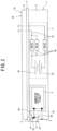
Fig. 2] Fig. 2 is a side view of a battery pack according to a second embodiment of this invention. - [
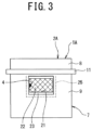
Fig. 3] Fig. 3 is a front view of the battery pack according to the second embodiment of this invention. - A battery pack according to embodiments of this invention includes: a battery; and a battery case accommodating the battery, in which the battery case includes a first conductive portion and a second conductive portion formed of a conductive material and exposed to an outer surface, in which an insulating member insulating the first conductive portion and the second conductive portion is provided between the first conductive portion and the second conductive portion, and in which a first contact electrically connected to the first conductive portion, a second contact electrically connected to the second conductive portion, and a submersion detection circuit detecting an electrical connection between the first contact and the second contact caused by the submersion of the first conductive portion and the second conductive portion are provided inside the battery case. Accordingly, the battery pack according to embodiments of this invention can detect the submersion of the battery case with a simple configuration.
- A battery pack of a vehicle according to a first embodiment of this invention will be described with reference to the drawings.
Fig. 1 is a view showing the battery pack according to the first embodiment of this invention. - In
Fig. 1 , abattery pack 1 includes a high-voltage battery 3 and abattery case 2 accommodating the high-voltage battery 3. Thebattery pack 1 is configured as an invehicle battery pack mounted in a vehicle such as an automobile (not shown), and supplies electric power to a driving motor provided in the vehicle via an inverter or the like. - The high-
voltage battery 3 includes a plurality ofbattery cells 3A, arelay 3B which switches the connection of the plurality ofbattery cells 3A, and alead wire 3C which connects thebattery cell 3A and therelay 3B and is drawn out of thebattery case 2. The high-voltage battery 3 generates a high voltage by connecting the plurality ofbattery cells 3A in series with thelead wire 3C. The high-voltage battery 3 constitutes the battery of this invention. - The
battery case 2 includes anupper casing 8 and alower casing 9 which are joined together to form a sealed space that accommodates the high-voltage battery 3. Theupper casing 8 and thelower casing 9 constitute a casing body 7 which accommodates the high-voltage battery 3. Theupper casing 8 constitutes the first casing and the first conductive portion of this invention and thelower casing 9 constitutes the second casing and the second conductive portion of this invention. - The
upper casing 8 and thelower casing 9 are formed of a conductive material and are exposed to the outer surface. As the conductive material, for example, metal such as iron can be used. Additionally, the outer surfaces of theupper casing 8 and thelower casing 9 may be coated with a non-conductive material if at least a part of theupper casing 8 and at least a part of thelower casing 9 are exposed to the outer surface. - An
insulating member 12 for electrically insulating theupper casing 8 and thelower casing 9 is provided at the joint between theupper casing 8 and thelower casing 9. Further, aseal member 11 is provided between theupper casing 8 and thelower casing 9 to liquid-tightly join theupper casing 8 and thelower casing 9. - A
first contact 4 electrically connected to theupper casing 8 and asecond contact 5 electrically connected to thelower casing 9 are provided inside thebattery case 2. In this embodiment, thefirst contact 4 is connected to the inner wall surface (lower surface) of theupper casing 8 and thesecond contact 5 is connected to the inner wall surface of thelower casing 9 on the front side. - A
submersion detection circuit 6 is provided inside thebattery case 2. Thesubmersion detection circuit 6 is electrically connected to thefirst contact 4 via alead wire 4A and is electrically connected to thesecond contact 5 via alead wire 5A. - The
submersion detection circuit 6 detects the electrical connection between thefirst contact 4 and thesecond contact 5 caused by the submersion of theupper casing 8 and thelower casing 9. - In the
battery pack 1 with such a configuration, when theupper casing 8 and thelower casing 9 formed of a conductive material are submerged, theupper casing 8 and thelower casing 9 are electrically connected to each other through water to have the same potential and thefirst contact 4 and thesecond contact 5 are also electrically connected to each other to have the same potential. Therefore, thesubmersion detection circuit 6 can determine that thebattery case 2 has been submerged under the condition that thefirst contact 4 and thesecond contact 5 are electrically connected. - As described above, in this embodiment, the
battery case 2 includes theupper casing 8 and thelower casing 9 which are formed of a conductive material and are exposed to the outer surface and the insulatingmember 12 insulating theupper casing 8 and thelower casing 9 is provided between theupper casing 8 and thelower casing 9. Further, thefirst contact 4 electrically connected to theupper casing 8, thesecond contact 5 electrically connected to thelower casing 9, and thesubmersion detection circuit 6 detecting the electrical connection between thefirst contact 4 and thesecond contact 5 caused by the submersion of theupper casing 8 and thelower casing 9 are provided inside thebattery case 2. - Accordingly, it is possible to detect the submersion of the
battery case 2 without providing a submersion sensor outside thebattery case 2 by detecting the electrical connection between thefirst contact 4 and thesecond contact 5 caused by the submersion of theupper casing 8 and thelower casing 9 of thebattery case 2. As a result, the submersion of thebattery case 2 can be detected with a simple configuration. - Further, in this embodiment, the
battery case 2 includes theupper casing 8 which is the first conductive portion and thelower casing 9 which is the second conductive portion and these casings are joined to each other to form a closed space accommodating the high-voltage battery 3. Then, theinsulating member 12 is provided at the joint between theupper casing 8 and thelower casing 9. - Accordingly, the first conductive portion and the second conductive portion can be respectively configured by using the
upper casing 8 and thelower casing 9 generally provided in thebattery case 2. Therefore, it is possible to detect the submersion of thebattery case 2 with a simple configuration. - A battery pack of a vehicle according to a second embodiment of this invention will be described with reference to the drawings.
Figs. 2 and3 are views showing the battery pack according to the second embodiment of this invention. Additionally, the same members as in the first embodiment will be described with the same reference numerals as in the first embodiment. - In
Figs. 2 and3 , abattery pack 1A includes the high-voltage battery 3 and abattery case 2A which accommodates the high-voltage battery 3. - The
battery case 2A includes theupper casing 8 and thelower casing 9 which are joined to each other to form a closed space accommodating the high-voltage battery 3. Theupper casing 8 and thelower casing 9 constitute the casing body 7 accommodating the high-voltage battery 3. - The
battery case 2A includes avent 21 which is opened to the wall surface of the casing body 7 and adjusts the inner pressure of the casing body 7 and afilter member 22 that is provided in thevent 21 and prevents dusts from entering the casing body 7 from thevent 21. Thefilter member 22 constitutes the first conductive portion of this invention and the casing body 7 constitutes the second conductive portion of this invention. - The
filter member 22 and the casing body 7 are formed of a conductive material and are exposed to the outer surface. Theseal member 11 is provided at the joint between theupper casing 8 and thelower casing 9. Thevent 21 has a square shape and is disposed on the wall surface of thelower casing 9 of the casing body 7 on the front side. Thefilter member 22 is made of a mesh filter in which fine wires of metal such as iron are formed in a mesh shape. Additionally, in this embodiment, thevent 21 and thefilter member 22 are provided on the wall surface of thelower casing 9 in the casing body 7, but thevent 21 and thefilter member 22 may be provided on the wall surface of theupper casing 8 instead of thelower casing 9. - An insulating
member 23 electrically insulating thefilter member 22 and the casing body 7 is provided at the joint between thefilter member 22 and the casing body 7. - The
first contact 4 electrically connected to thefilter member 22 and thesecond contact 5 electrically connected to the casing body 7 are provided inside thebattery case 2A. In this embodiment, thefirst contact 4 is connected to the edge portion of thefilter member 22 and thesecond contact 5 is connected to the inner wall surface of thelower casing 9 of the casing body 7 on the front side. - The
submersion detection circuit 6 is provided inside thebattery case 2A. Thesubmersion detection circuit 6 is electrically connected to thefirst contact 4 via thelead wire 4A and is electrically connected to thesecond contact 5 via thelead wire 5A. - The
submersion detection circuit 6 detects the electrical connection between thefirst contact 4 and thesecond contact 5 caused by the submersion of thefilter member 22 and the casing body 7. - In the
battery pack 1A with such a configuration, when thefilter member 22 and the casing body 7 formed of a conductive material are submerged, thefilter member 22 and the casing body 7 are electrically connected to each other through water to have the same potential and thefirst contact 4 and thesecond contact 5 are also electrically connected to each other to have the same potential. Therefore, thesubmersion detection circuit 6 can determine that thebattery case 2A has been submerged under the condition that thefirst contact 4 and thesecond contact 5 are electrically connected. - Additionally, it is preferable that a
partition wall 25 indicated by a dashed line inFigs. 2 and3 is provided inside the casing body 7 to suppress water from entering through thevent 21. Thepartition wall 25 is disposed inside thevent 21 in the casing body 7 and is formed in a U-shape in the plan view or an L-shape in the side view. Thepartition wall 25 covers the bottom surface and the side surface of the inner space of thevent 21 and thefilter member 22. Accordingly, air inside the casing body 7 passes above thepartition wall 25 to reach thevent 21 and exit to the outside as indicated by an arrow A (seeFig. 2 ). Conversely, the air that has entered from the outside of the casing body 7 through thevent 21 can enter further inside while passing above thepartition wall 25. - As described above, in this embodiment, the
battery case 2A includes thefilter member 22 and the casing body 7 formed of a conductive material and exposed to the outer surface and the insulatingmember 23 insulating thefilter member 22 and the casing body 7 is provided between thefilter member 22 and the casing body 7. Then, thefirst contact 4 electrically connected to thefilter member 22, thesecond contact 5 electrically connected to the casing body 7, and thesubmersion detection circuit 6 detecting the electrical connection between thefirst contact 4 and thesecond contact 5 caused by the submersion of thefilter member 22 and the casing body 7 are provided inside thebattery case 2A. - Accordingly, it is possible to detect the submersion of the
battery pack 1A without providing the submersion sensor outside thebattery case 2A by detecting the electrical connection between thefirst contact 4 and thesecond contact 5 caused by the submersion of the casing body 7 and thefilter member 22 of thebattery case 2A. As a result, it is possible to detect the submersion of thebattery case 2A with a simple configuration. - Further, in this embodiment, the
battery case 2A includes the casing body 7 which is the second conductive portion accommodating the high-voltage battery 3, thevent 21 which is opened to the wall surface of the casing body 7 and adjusts the inner pressure of the casing body 7, and thefilter member 22 that is provided in thevent 21 and is the first conductive portion preventing dust from entering the casing body 7 from thevent 21. Then, the insulatingmember 23 is provided at the joint between thefilter member 22 and the casing body 7. - Accordingly, the first conductive portion and the second conductive portion can be respectively configured by using the casing body 7 and the
vent 21 which are the members generally provided in thebattery case 2A. Therefore, it is possible to detect the submersion of thebattery case 2A with a simple configuration. - While embodiments of this invention have been described, it is apparent that some artisan could have made changes without departing from the scope of this invention. It is intended that any and all such modifications and equivalents are involved in the appended claims.
- 1, 1A ... Battery pack, 2, 2A ... Battery case, 3 ... High-voltage battery (battery), 4 ... First contact, 5 ... Second contact, 6 ... Submersion detection circuit, 7 ... Casing body (second conductive portion), 8 ... Upper casing (first conductive portion, first casing), 9 ... Lower casing (second conductive portion, second casing), 12, 23 ... Insulating member, 21 ... Vent, 22 ... Filter member (first conductive portion)
Claims (3)
- A battery pack (1, 1A) comprising:a battery (3); anda battery case (2, 2A) accommodating the battery (3),wherein the battery case (2, 2A) includes a first conductive portion (8, 22) and a second conductive portion (7, 9) formed of a conductive material and exposed to an outer surface,wherein an insulating member (12, 23) insulating the first conductive portion (8, 22) and the second conductive portion (7, 9) is provided between the first conductive portion (8, 22) and the second conductive portion (7, 9), andwherein a first contact (4) electrically connected to the first conductive portion (8, 22), a second contact (5) electrically connected to the second conductive portion (7, 9), and a submersion detection circuit (6) detecting an electrical connection between the first contact (4) and the second contact (5) caused by the submersion of the first conductive portion (8, 22) and the second conductive portion (7, 9) are provided inside the battery case (2, 2A).
- The battery pack according to claim 1,wherein the battery case (2, 2A) includes a first casing (8) and a second casing (9) joined to each other to form a closed space accommodating the battery (3),wherein the first casing (8) constitutes the first conductive portion,wherein the second casing (9) constitutes the second conductive portion, andwherein the insulating member (12) is provided at the joint between the first casing (8) and the second casing (9).
- The battery pack according to claim 1,wherein the battery case (2, 2A) includes a casing body (7) accommodating the battery (3), a vent (21) opened to a wall surface of the casing body (7) and adjusting an inner pressure of the casing body (7), and a filter member (22) provided in the vent (21) and preventing dust from entering the casing body (7) from the vent (21),wherein the filter member (22) constitutes the first conductive portion,wherein the casing body (7) constitutes the second conductive portion, andwherein the insulating member (23) is provided at the joint between the filter member (22) and the casing body (7).
Applications Claiming Priority (1)
| Application Number | Priority Date | Filing Date | Title |
|---|---|---|---|
| JP2022005203A JP7732360B2 (en) | 2022-01-17 | 2022-01-17 | Battery pack |
Publications (3)
| Publication Number | Publication Date |
|---|---|
| EP4254640A2 true EP4254640A2 (en) | 2023-10-04 |
| EP4254640A3 EP4254640A3 (en) | 2024-06-12 |
| EP4254640B1 EP4254640B1 (en) | 2025-02-19 |
Family
ID=84370416
Family Applications (1)
| Application Number | Title | Priority Date | Filing Date |
|---|---|---|---|
| EP22210760.9A Active EP4254640B1 (en) | 2022-01-17 | 2022-12-01 | Battery pack |
Country Status (2)
| Country | Link |
|---|---|
| EP (1) | EP4254640B1 (en) |
| JP (1) | JP7732360B2 (en) |
Citations (1)
| Publication number | Priority date | Publication date | Assignee | Title |
|---|---|---|---|---|
| JP2019040700A (en) | 2017-08-23 | 2019-03-14 | 株式会社デンソー | Battery pack |
Family Cites Families (7)
| Publication number | Priority date | Publication date | Assignee | Title |
|---|---|---|---|---|
| JP3588343B2 (en) * | 2001-08-21 | 2004-11-10 | 三洋電機株式会社 | Battery pack |
| JP5970849B2 (en) * | 2012-02-21 | 2016-08-17 | 株式会社デンソー | Submergence detection device |
| JP6001360B2 (en) * | 2012-07-05 | 2016-10-05 | 株式会社デンソー | Battery unit |
| DE102013201411A1 (en) * | 2013-01-29 | 2014-07-31 | Robert Bosch Gmbh | Housing for accommodating battery e.g. lithium-ion battery mounted in vehicle, has sensor that is arranged for detecting liquid accumulation in housing, if liquid accumulation exceeds pre-defined level of liquid within housing |
| JP7047430B2 (en) * | 2018-02-08 | 2022-04-05 | 株式会社デンソー | Battery pack |
| JP7087769B2 (en) * | 2018-07-23 | 2022-06-21 | 株式会社デンソー | Battery pack |
| JP7351356B2 (en) * | 2020-01-27 | 2023-09-27 | 株式会社村田製作所 | Battery packs and power tools |
-
2022
- 2022-01-17 JP JP2022005203A patent/JP7732360B2/en active Active
- 2022-12-01 EP EP22210760.9A patent/EP4254640B1/en active Active
Patent Citations (1)
| Publication number | Priority date | Publication date | Assignee | Title |
|---|---|---|---|---|
| JP2019040700A (en) | 2017-08-23 | 2019-03-14 | 株式会社デンソー | Battery pack |
Also Published As
| Publication number | Publication date |
|---|---|
| JP7732360B2 (en) | 2025-09-02 |
| JP2023104299A (en) | 2023-07-28 |
| EP4254640A3 (en) | 2024-06-12 |
| EP4254640B1 (en) | 2025-02-19 |
Similar Documents
| Publication | Publication Date | Title |
|---|---|---|
| US9728901B2 (en) | Connector structure | |
| US9553290B2 (en) | Gas discharge structure for battery cover | |
| CN103257020B (en) | immersion detection device | |
| US20120276427A1 (en) | Rechargeable battery | |
| KR101711994B1 (en) | Rechargeable battery module | |
| US12218476B2 (en) | Terminal block configured to electrically relay through partition wall sealing a liquid | |
| CN113711452A (en) | Electrical connection box | |
| JP2021132022A (en) | Power storage device | |
| CN106953473B (en) | A housing with built-in controls and an electric compressor incorporating the housing | |
| EP4254640A2 (en) | Battery pack | |
| CN103091536B (en) | Current detecting equipment | |
| CN105280973A (en) | Battery cell | |
| CN114008845A (en) | Electricity storage device | |
| JP6376082B2 (en) | Battery pack | |
| JP2011117853A (en) | Current detector | |
| EP1629562A1 (en) | Insulating mount structure, insulation monitoring system, and insulation monitoring method for fuel cells | |
| CN108075053A (en) | Rechargeable battery bag | |
| JP2018073822A (en) | Electronic device | |
| CN211605327U (en) | A new type of packaging structure for lithium battery | |
| KR19980060785A (en) | battery | |
| JP7487243B2 (en) | Interlocking Structure | |
| CN209841277U (en) | Pressure sensor device for electric pump and electric pump | |
| JP2017149329A (en) | Car electronics case | |
| JP2020067319A (en) | Sensor | |
| JP2020067323A (en) | Sensor |
Legal Events
| Date | Code | Title | Description |
|---|---|---|---|
| PUAI | Public reference made under article 153(3) epc to a published international application that has entered the european phase |
Free format text: ORIGINAL CODE: 0009012 |
|
| STAA | Information on the status of an ep patent application or granted ep patent |
Free format text: STATUS: REQUEST FOR EXAMINATION WAS MADE |
|
| 17P | Request for examination filed |
Effective date: 20221201 |
|
| AK | Designated contracting states |
Kind code of ref document: A2 Designated state(s): AL AT BE BG CH CY CZ DE DK EE ES FI FR GB GR HR HU IE IS IT LI LT LU LV MC ME MK MT NL NO PL PT RO RS SE SI SK SM TR |
|
| PUAL | Search report despatched |
Free format text: ORIGINAL CODE: 0009013 |
|
| AK | Designated contracting states |
Kind code of ref document: A3 Designated state(s): AL AT BE BG CH CY CZ DE DK EE ES FI FR GB GR HR HU IE IS IT LI LT LU LV MC ME MK MT NL NO PL PT RO RS SE SI SK SM TR |
|
| RIC1 | Information provided on ipc code assigned before grant |
Ipc: H01M 50/531 20210101AFI20240507BHEP |
|
| GRAP | Despatch of communication of intention to grant a patent |
Free format text: ORIGINAL CODE: EPIDOSNIGR1 |
|
| STAA | Information on the status of an ep patent application or granted ep patent |
Free format text: STATUS: GRANT OF PATENT IS INTENDED |
|
| INTG | Intention to grant announced |
Effective date: 20241107 |
|
| GRAS | Grant fee paid |
Free format text: ORIGINAL CODE: EPIDOSNIGR3 |
|
| GRAA | (expected) grant |
Free format text: ORIGINAL CODE: 0009210 |
|
| STAA | Information on the status of an ep patent application or granted ep patent |
Free format text: STATUS: THE PATENT HAS BEEN GRANTED |
|
| AK | Designated contracting states |
Kind code of ref document: B1 Designated state(s): AL AT BE BG CH CY CZ DE DK EE ES FI FR GB GR HR HU IE IS IT LI LT LU LV MC ME MK MT NL NO PL PT RO RS SE SI SK SM TR |
|
| REG | Reference to a national code |
Ref country code: GB Ref legal event code: FG4D |
|
| REG | Reference to a national code |
Ref country code: CH Ref legal event code: EP |
|
| REG | Reference to a national code |
Ref country code: IE Ref legal event code: FG4D |
|
| REG | Reference to a national code |
Ref country code: DE Ref legal event code: R096 Ref document number: 602022010791 Country of ref document: DE |
|
| REG | Reference to a national code |
Ref country code: NL Ref legal event code: MP Effective date: 20250219 |
|
| PG25 | Lapsed in a contracting state [announced via postgrant information from national office to epo] |
Ref country code: RS Free format text: LAPSE BECAUSE OF FAILURE TO SUBMIT A TRANSLATION OF THE DESCRIPTION OR TO PAY THE FEE WITHIN THE PRESCRIBED TIME-LIMIT Effective date: 20250519 |
|
| PG25 | Lapsed in a contracting state [announced via postgrant information from national office to epo] |
Ref country code: FI Free format text: LAPSE BECAUSE OF FAILURE TO SUBMIT A TRANSLATION OF THE DESCRIPTION OR TO PAY THE FEE WITHIN THE PRESCRIBED TIME-LIMIT Effective date: 20250219 |
|
| PG25 | Lapsed in a contracting state [announced via postgrant information from national office to epo] |
Ref country code: PL Free format text: LAPSE BECAUSE OF FAILURE TO SUBMIT A TRANSLATION OF THE DESCRIPTION OR TO PAY THE FEE WITHIN THE PRESCRIBED TIME-LIMIT Effective date: 20250219 |
|
| PG25 | Lapsed in a contracting state [announced via postgrant information from national office to epo] |
Ref country code: ES Free format text: LAPSE BECAUSE OF FAILURE TO SUBMIT A TRANSLATION OF THE DESCRIPTION OR TO PAY THE FEE WITHIN THE PRESCRIBED TIME-LIMIT Effective date: 20250219 |
|
| REG | Reference to a national code |
Ref country code: LT Ref legal event code: MG9D |
|
| PG25 | Lapsed in a contracting state [announced via postgrant information from national office to epo] |
Ref country code: IS Free format text: LAPSE BECAUSE OF FAILURE TO SUBMIT A TRANSLATION OF THE DESCRIPTION OR TO PAY THE FEE WITHIN THE PRESCRIBED TIME-LIMIT Effective date: 20250619 Ref country code: NO Free format text: LAPSE BECAUSE OF FAILURE TO SUBMIT A TRANSLATION OF THE DESCRIPTION OR TO PAY THE FEE WITHIN THE PRESCRIBED TIME-LIMIT Effective date: 20250519 |
|
| PG25 | Lapsed in a contracting state [announced via postgrant information from national office to epo] |
Ref country code: NL Free format text: LAPSE BECAUSE OF FAILURE TO SUBMIT A TRANSLATION OF THE DESCRIPTION OR TO PAY THE FEE WITHIN THE PRESCRIBED TIME-LIMIT Effective date: 20250219 |
|
| PG25 | Lapsed in a contracting state [announced via postgrant information from national office to epo] |
Ref country code: HR Free format text: LAPSE BECAUSE OF FAILURE TO SUBMIT A TRANSLATION OF THE DESCRIPTION OR TO PAY THE FEE WITHIN THE PRESCRIBED TIME-LIMIT Effective date: 20250219 |
|
| PG25 | Lapsed in a contracting state [announced via postgrant information from national office to epo] |
Ref country code: PT Free format text: LAPSE BECAUSE OF FAILURE TO SUBMIT A TRANSLATION OF THE DESCRIPTION OR TO PAY THE FEE WITHIN THE PRESCRIBED TIME-LIMIT Effective date: 20250620 Ref country code: LV Free format text: LAPSE BECAUSE OF FAILURE TO SUBMIT A TRANSLATION OF THE DESCRIPTION OR TO PAY THE FEE WITHIN THE PRESCRIBED TIME-LIMIT Effective date: 20250219 |
|
| PG25 | Lapsed in a contracting state [announced via postgrant information from national office to epo] |
Ref country code: GR Free format text: LAPSE BECAUSE OF FAILURE TO SUBMIT A TRANSLATION OF THE DESCRIPTION OR TO PAY THE FEE WITHIN THE PRESCRIBED TIME-LIMIT Effective date: 20250520 Ref country code: BG Free format text: LAPSE BECAUSE OF FAILURE TO SUBMIT A TRANSLATION OF THE DESCRIPTION OR TO PAY THE FEE WITHIN THE PRESCRIBED TIME-LIMIT Effective date: 20250219 |
|
| REG | Reference to a national code |
Ref country code: AT Ref legal event code: MK05 Ref document number: 1769239 Country of ref document: AT Kind code of ref document: T Effective date: 20250219 |
|
| PG25 | Lapsed in a contracting state [announced via postgrant information from national office to epo] |
Ref country code: SE Free format text: LAPSE BECAUSE OF FAILURE TO SUBMIT A TRANSLATION OF THE DESCRIPTION OR TO PAY THE FEE WITHIN THE PRESCRIBED TIME-LIMIT Effective date: 20250219 |
|
| PG25 | Lapsed in a contracting state [announced via postgrant information from national office to epo] |
Ref country code: SM Free format text: LAPSE BECAUSE OF FAILURE TO SUBMIT A TRANSLATION OF THE DESCRIPTION OR TO PAY THE FEE WITHIN THE PRESCRIBED TIME-LIMIT Effective date: 20250219 |
|
| PG25 | Lapsed in a contracting state [announced via postgrant information from national office to epo] |
Ref country code: DK Free format text: LAPSE BECAUSE OF FAILURE TO SUBMIT A TRANSLATION OF THE DESCRIPTION OR TO PAY THE FEE WITHIN THE PRESCRIBED TIME-LIMIT Effective date: 20250219 |
|
| PG25 | Lapsed in a contracting state [announced via postgrant information from national office to epo] |
Ref country code: IT Free format text: LAPSE BECAUSE OF FAILURE TO SUBMIT A TRANSLATION OF THE DESCRIPTION OR TO PAY THE FEE WITHIN THE PRESCRIBED TIME-LIMIT Effective date: 20250219 |
|
| PG25 | Lapsed in a contracting state [announced via postgrant information from national office to epo] |
Ref country code: AT Free format text: LAPSE BECAUSE OF FAILURE TO SUBMIT A TRANSLATION OF THE DESCRIPTION OR TO PAY THE FEE WITHIN THE PRESCRIBED TIME-LIMIT Effective date: 20250219 |
|
| PG25 | Lapsed in a contracting state [announced via postgrant information from national office to epo] |
Ref country code: EE Free format text: LAPSE BECAUSE OF FAILURE TO SUBMIT A TRANSLATION OF THE DESCRIPTION OR TO PAY THE FEE WITHIN THE PRESCRIBED TIME-LIMIT Effective date: 20250219 Ref country code: CZ Free format text: LAPSE BECAUSE OF FAILURE TO SUBMIT A TRANSLATION OF THE DESCRIPTION OR TO PAY THE FEE WITHIN THE PRESCRIBED TIME-LIMIT Effective date: 20250219 |
|
| PG25 | Lapsed in a contracting state [announced via postgrant information from national office to epo] |
Ref country code: RO Free format text: LAPSE BECAUSE OF FAILURE TO SUBMIT A TRANSLATION OF THE DESCRIPTION OR TO PAY THE FEE WITHIN THE PRESCRIBED TIME-LIMIT Effective date: 20250219 |
|
| PG25 | Lapsed in a contracting state [announced via postgrant information from national office to epo] |
Ref country code: SK Free format text: LAPSE BECAUSE OF FAILURE TO SUBMIT A TRANSLATION OF THE DESCRIPTION OR TO PAY THE FEE WITHIN THE PRESCRIBED TIME-LIMIT Effective date: 20250219 |
|
| REG | Reference to a national code |
Ref country code: DE Ref legal event code: R097 Ref document number: 602022010791 Country of ref document: DE |
|
| PLBE | No opposition filed within time limit |
Free format text: ORIGINAL CODE: 0009261 |
|
| STAA | Information on the status of an ep patent application or granted ep patent |
Free format text: STATUS: NO OPPOSITION FILED WITHIN TIME LIMIT |
|
| PGFP | Annual fee paid to national office [announced via postgrant information from national office to epo] |
Ref country code: DE Payment date: 20251028 Year of fee payment: 4 |
|
| PGFP | Annual fee paid to national office [announced via postgrant information from national office to epo] |
Ref country code: FR Payment date: 20251110 Year of fee payment: 4 |
|
| 26N | No opposition filed |
Effective date: 20251120 |