EP4254632A1 - Battery cover plate assembly, cylindrical battery, and battery pack - Google Patents
Battery cover plate assembly, cylindrical battery, and battery pack Download PDFInfo
- Publication number
- EP4254632A1 EP4254632A1 EP22817059.3A EP22817059A EP4254632A1 EP 4254632 A1 EP4254632 A1 EP 4254632A1 EP 22817059 A EP22817059 A EP 22817059A EP 4254632 A1 EP4254632 A1 EP 4254632A1
- Authority
- EP
- European Patent Office
- Prior art keywords
- cap
- battery
- plastic member
- cap assembly
- pole
- Prior art date
- Legal status (The legal status is an assumption and is not a legal conclusion. Google has not performed a legal analysis and makes no representation as to the accuracy of the status listed.)
- Pending
Links
Images
Classifications
-
- H—ELECTRICITY
- H01—ELECTRIC ELEMENTS
- H01M—PROCESSES OR MEANS, e.g. BATTERIES, FOR THE DIRECT CONVERSION OF CHEMICAL ENERGY INTO ELECTRICAL ENERGY
- H01M50/00—Constructional details or processes of manufacture of the non-active parts of electrochemical cells other than fuel cells, e.g. hybrid cells
- H01M50/10—Primary casings; Jackets or wrappings
- H01M50/14—Primary casings; Jackets or wrappings for protecting against damage caused by external factors
- H01M50/143—Fireproof; Explosion-proof
-
- H—ELECTRICITY
- H01—ELECTRIC ELEMENTS
- H01M—PROCESSES OR MEANS, e.g. BATTERIES, FOR THE DIRECT CONVERSION OF CHEMICAL ENERGY INTO ELECTRICAL ENERGY
- H01M50/00—Constructional details or processes of manufacture of the non-active parts of electrochemical cells other than fuel cells, e.g. hybrid cells
- H01M50/10—Primary casings; Jackets or wrappings
- H01M50/147—Lids or covers
- H01M50/148—Lids or covers characterised by their shape
- H01M50/152—Lids or covers characterised by their shape for cells having curved cross-section, e.g. round or elliptic
-
- H—ELECTRICITY
- H01—ELECTRIC ELEMENTS
- H01M—PROCESSES OR MEANS, e.g. BATTERIES, FOR THE DIRECT CONVERSION OF CHEMICAL ENERGY INTO ELECTRICAL ENERGY
- H01M50/00—Constructional details or processes of manufacture of the non-active parts of electrochemical cells other than fuel cells, e.g. hybrid cells
- H01M50/10—Primary casings; Jackets or wrappings
- H01M50/147—Lids or covers
- H01M50/166—Lids or covers characterised by the methods of assembling casings with lids
- H01M50/169—Lids or covers characterised by the methods of assembling casings with lids by welding, brazing or soldering
-
- H—ELECTRICITY
- H01—ELECTRIC ELEMENTS
- H01M—PROCESSES OR MEANS, e.g. BATTERIES, FOR THE DIRECT CONVERSION OF CHEMICAL ENERGY INTO ELECTRICAL ENERGY
- H01M50/00—Constructional details or processes of manufacture of the non-active parts of electrochemical cells other than fuel cells, e.g. hybrid cells
- H01M50/10—Primary casings; Jackets or wrappings
- H01M50/183—Sealing members
- H01M50/184—Sealing members characterised by their shape or structure
-
- H—ELECTRICITY
- H01—ELECTRIC ELEMENTS
- H01M—PROCESSES OR MEANS, e.g. BATTERIES, FOR THE DIRECT CONVERSION OF CHEMICAL ENERGY INTO ELECTRICAL ENERGY
- H01M50/00—Constructional details or processes of manufacture of the non-active parts of electrochemical cells other than fuel cells, e.g. hybrid cells
- H01M50/10—Primary casings; Jackets or wrappings
- H01M50/183—Sealing members
- H01M50/186—Sealing members characterised by the disposition of the sealing members
-
- H—ELECTRICITY
- H01—ELECTRIC ELEMENTS
- H01M—PROCESSES OR MEANS, e.g. BATTERIES, FOR THE DIRECT CONVERSION OF CHEMICAL ENERGY INTO ELECTRICAL ENERGY
- H01M50/00—Constructional details or processes of manufacture of the non-active parts of electrochemical cells other than fuel cells, e.g. hybrid cells
- H01M50/30—Arrangements for facilitating escape of gases
- H01M50/342—Non-re-sealable arrangements
-
- H—ELECTRICITY
- H01—ELECTRIC ELEMENTS
- H01M—PROCESSES OR MEANS, e.g. BATTERIES, FOR THE DIRECT CONVERSION OF CHEMICAL ENERGY INTO ELECTRICAL ENERGY
- H01M50/00—Constructional details or processes of manufacture of the non-active parts of electrochemical cells other than fuel cells, e.g. hybrid cells
- H01M50/30—Arrangements for facilitating escape of gases
- H01M50/342—Non-re-sealable arrangements
- H01M50/3425—Non-re-sealable arrangements in the form of rupturable membranes or weakened parts, e.g. pierced with the aid of a sharp member
-
- H—ELECTRICITY
- H01—ELECTRIC ELEMENTS
- H01M—PROCESSES OR MEANS, e.g. BATTERIES, FOR THE DIRECT CONVERSION OF CHEMICAL ENERGY INTO ELECTRICAL ENERGY
- H01M50/00—Constructional details or processes of manufacture of the non-active parts of electrochemical cells other than fuel cells, e.g. hybrid cells
- H01M50/60—Arrangements or processes for filling or topping-up with liquids; Arrangements or processes for draining liquids from casings
- H01M50/609—Arrangements or processes for filling with liquid, e.g. electrolytes
- H01M50/627—Filling ports
-
- H—ELECTRICITY
- H01—ELECTRIC ELEMENTS
- H01M—PROCESSES OR MEANS, e.g. BATTERIES, FOR THE DIRECT CONVERSION OF CHEMICAL ENERGY INTO ELECTRICAL ENERGY
- H01M50/00—Constructional details or processes of manufacture of the non-active parts of electrochemical cells other than fuel cells, e.g. hybrid cells
- H01M50/60—Arrangements or processes for filling or topping-up with liquids; Arrangements or processes for draining liquids from casings
- H01M50/609—Arrangements or processes for filling with liquid, e.g. electrolytes
- H01M50/627—Filling ports
- H01M50/636—Closing or sealing filling ports, e.g. using lids
- H01M50/645—Plugs
-
- Y—GENERAL TAGGING OF NEW TECHNOLOGICAL DEVELOPMENTS; GENERAL TAGGING OF CROSS-SECTIONAL TECHNOLOGIES SPANNING OVER SEVERAL SECTIONS OF THE IPC; TECHNICAL SUBJECTS COVERED BY FORMER USPC CROSS-REFERENCE ART COLLECTIONS [XRACs] AND DIGESTS
- Y02—TECHNOLOGIES OR APPLICATIONS FOR MITIGATION OR ADAPTATION AGAINST CLIMATE CHANGE
- Y02E—REDUCTION OF GREENHOUSE GAS [GHG] EMISSIONS, RELATED TO ENERGY GENERATION, TRANSMISSION OR DISTRIBUTION
- Y02E60/00—Enabling technologies; Technologies with a potential or indirect contribution to GHG emissions mitigation
- Y02E60/10—Energy storage using batteries
Definitions
- the present disclosure relates to the field of battery technologies, for example, to a cap assembly of a battery, a cylindrical battery, and a battery pack.
- the explosion-proof valve is configured to be firstly cracked when the battery fails, in order to relieve a pressure of the battery and ensure the safety of the battery.
- one way for arranging the liquid injection hole and the explosion-proof valve is to arrange the liquid injection hole and the explosion-proof valve on the same cap of the battery.
- the above arrangement limits a diameter of the liquid injection hole, and the liquid injection hole having a smaller size not only is inconvenient for processing, but also affects the liquid injection process.
- Another way is to define the liquid injection hole on one of the caps at one end of the battery, and arrange the explosion-proof valve on the other of the caps at the other end of the battery. In this case, the two caps are needed to be defined with holes, respectively, which is cumbersome and costly in manufacturing.
- the present disclosure provides a cap assembly of a battery, a cylindrical battery, and a battery pack, which have a simple manufacturing process, a high production efficiency, few parts, a low cost, and can ensure that the liquid injection hole has a diameter large enough, and can make the liquid injection process stable.
- a cap assembly of a battery in some embodiments of the present disclosure.
- the cap assembly includes a cap, defining a liquid injection hole; a pole, disposed on a first side of the cap; a terminal, disposed on a second side of the cap and electrically connected to the pole.
- the second side of the cap is opposite to the first side of the cap; and a sealing pin, configured to seal the liquid injection hole, and having a thinning region configured for an explosion-proof function.
- a thickness of the thinning region is less than or equal to 0.2mm.
- the sealing pin defines a notch, and a position of the sealing pin corresponding to the notch forms the thinning region.
- the sealing pin defines two notches, and the two notches are intersected with each other.
- the sealing pin further defines a recess, the recess is located at one of two opposite sides of the sealing pin, the notch is located at the other of two opposite sides of the sealing pin, and the recess is disposed directly opposite to the notch.
- the liquid injection hole is a stepped hole, one end of the stepped hole having a greater diameter faces the second side of the cap, and the sealing pin is sealed to the end of the stepped hole having a greater diameter.
- an inner wall surface at the end of the stepped hole having a greater diameter is a tapered surface, a diameter of the tapered surface gradually decreases along a direction from the second side of the cap to the first side of the cap, and a peripheral wall surface of the sealing pin is a tapered face.
- the sealing pin is welded to a hole wall of the liquid injection hole.
- the cap defines a mounting hole
- the cap assembly of the battery further includes: an upper plastic member, disposed between the cap and the terminal; a lower plastic member, disposed between the pole and the cap; and a sealing ring, disposed in the mounting hole and abutting against both the upper plastic member and the lower plastic member.
- the pole successively runs through the lower plastic member, the sealing ring, and the upper plastic member, and is further connected to the terminal.
- the lower plastic member defines an avoidance hole at a position opposite to the liquid injection hole, and the avoidance hole has a diameter less than or equal to that of the liquid injection hole.
- the terminal defines a limiting groove at one end away from the cap, a first end of the pole close to the first side of the cap is arranged with a first flange, a second end of the pole close to the second side of the cap is arranged with a second flange, the first flange abuts against the lower plastic member, and the second flange is engaged into the limiting groove.
- one of a side wall of the upper plastic member facing the terminal and a side wall of the terminal facing the upper plastic member is arranged with a positioning protrusion
- the other of the side wall of the upper plastic member facing the terminal and the side wall of the terminal facing the upper plastic member defines a positioning groove, and the positioning protrusion is engaged with the positioning groove.
- one of a side wall of the upper plastic member facing the cap and a side wall of the cap facing the upper plastic member is arranged with a protruding portion, the other of the side wall of the upper plastic member facing the cap and the side wall of the cap facing the upper plastic member defines a groove portion, and the protruding portion is engaged with the groove portion.
- the cap assembly further includes a current collector.
- a first end of the current collector is arranged to be connected to a cell, and a second end of the current collector is electrically connected to the pole; the second end of the current collector is sandwiched between the lower plastic member and the pole and defines a through hole, and the pole runs through the through hole.
- a cylindrical battery in some embodiments of the present disclosure.
- the cylindrical battery includes a cylindrical shell, defining an opening; and a cap assembly as previously described.
- the cap assembly is configured to cover and seal the opening.
- a battery pack in some embodiments of the present disclosure.
- the battery pack includes a plurality of cylindrical batteries as previously described.
- the sealing pin by setting the thinning area on the sealing pin configured to seal the liquid injection hole, the sealing pin may have a function of an explosion-proof valve.
- an explosion-proof valve On one hand, it's unnecessary to additionally arrange an explosion-proof valve on the cap assembly, which reduces the number of components, thereby reducing cost and improving a production efficiency of the cap assembly.
- it's unnecessary to additionally define a mounting hole on the cap to mount the explosion-proof valve which can not only further improve the production efficiency of the cap assembly, but also leave a large arrangement space for the liquid injection hole on the cap, such that the liquid injection hole has a diameter large enough, thereby ensuring the stability of the liquid injection process.
- the cylindrical battery of the present embodiment by arranging the cap assembly of the battery as described above, has a simple manufacturing process, a high production efficiency, and a low cost, and the liquid injection process has a good stability, thereby ensuring a good performance.
- the battery pack of the present embodiment by setting the cylindrical battery as described above, has a high production efficiency, a low cost, and a good performance.
- a first feature being “above” or “below” a second features may include that the first feature directly contacts with the second feature, and may also include that the first feature does not directly contact with the second feature but contacts with the second feature through additional feature between the first feature and the second feature.
- the first feature being “above”, “on”, and “on top of' the second feature includes the first feature being directly above and diagonally above the second feature, or indicates that a horizontal height of the first feature is higher than a horizontal height of the second feature.
- the first feature being “below”, “under”, and “beneath” the second feature includes the first feature being directly below and diagonally below the second feature, or indicates that a horizontal height of the first feature is lower than a horizontal height of the second feature.
- orientations or positional relationships indicated by terms “up”, “down”, “left”, “right”, etc. are based on the orientations or position relationships shown in the accompanying drawings, and are only for the convenience of describing the present disclosure and simplifying the description, rather than implying or indicating that the device or the component referred to must have a particular orientation or constructed and operated in a particular orientation, and thus these terms cannot be understood as limiting the present disclosure.
- terms “first” and “second” are only used for distinguishing in description and have no special meaning.
- a cap assembly of a battery, a cylindrical battery, and a battery pack are provided.
- the battery pack includes a plurality of cylindrical batteries.
- the cylindrical battery includes a cylindrical shell 10, a cell 30, and a cap assembly.
- An opening 20 is defined at one end face of the shell 10, and the cell 30 is able to be put or placed into the shell 10 from the opening.
- the cap assembly is configured to cover and seal the opening of the housing 20. It should be noted that, in some embodiments, an inner side and an outer side are described with reference to the cylindrical battery. A side of the cap assembly facing an interior of the shell 10 is referred as the "inner side", and a side of the cap assembly facing an exterior of the shell 10 is referred as the "outer side".
- the cap assembly of the battery includes a cap 1, a pole 2, and a terminal 3.
- the cap 1 is arranged to block the opening at the end of the shell.
- the pole 2 is disposed on a first side of the cap 1, and the first side of the cap 1 is the inner side of the cap 1.
- the pole 2 is electrically connected to the cell inside the shell.
- the terminal 3 is disposed on a second side of the cap 1, and the second side of the cap 1 is the outer side of the cap 1.
- the pole 2 is further is electrically connected to the terminal 3.
- the terminal 3 is arranged to be connected to an external load. In this way, it is possible to realize the electrical connection between the cell and the external load outside the cylindrical battery.
- the cap 1 is in shape of substantially a circle.
- a mounting hole 12 is defined in the cap 1.
- the mounting hole 12 penetrates through the cap 1.
- the cap assembly of the battery further includes an upper plastic member 5, a lower plastic member 6, and a sealing ring 7.
- the upper plastic member 5 is arranged on the outer side of the cap 1 and located between the cap 1 and the terminal 3.
- the lower plastic member 6 is arranged on the inner side of the cap 1 and located between the pole 2 and the cap 1.
- the sealing ring 7 is arranged in the mounting hole 12 and abuts against the upper plastic member 5 and the lower plastic member 6, respectively.
- the pole 2 successively runs through the lower plastic member 6, the sealing ring 7, and the upper plastic member 5, and is further connected to the terminal 3.
- the arrangement of the upper plastic member 5, the sealing ring 7, and the lower plastic member 6 not only insulates the pole 2 from the cap 1, but also provides a sealing between the pole 2 and the cap 1.
- a limiting groove 31 is defined at a first end of the terminal 3 away from the cap 1.
- An end of the pole 2 is located on the inner side of the cap 1 and arranged with a first flange 21.
- a second flange 22 is disposed at a second end of the terminal 3.
- the first flange 21 abuts against the lower plastic member 6, and the second flange 22 is engaged in the limiting groove 31.
- one of a side wall of the upper plastic member 5 facing the cap 1 and a side wall of the cap 1 facing the upper plastic member 5 is arranged with a protruding portion 51, and the other of the side wall of the upper plastic member 5 facing the cap 1 and the side wall of the cap 1 facing the upper plastic member 5 defines a groove portion 13.
- the protruding portion 51 is engaged with the groove portion 13.
- the protruding portion 51 is disposed on the side wall of the upper plastic member 5 facing the cap 1, and the groove portion 13 is defined on the side wall of the cap 1 facing the upper plastic member 5.
- the groove portion 13 is arranged coaxially with the mounting hole 12, but the groove portion 13 is a non-circular groove, thereby better preventing the upper plastic member 5 from being twisted relative to the cap 1.
- the position of the protruding portion 51 may be interchangeable with the position of the groove portion 13.
- one of a side wall of the upper plastic member 5 facing the terminal 3 and a side wall of the terminal 3 facing the upper plastic member 5 is arranged with a positioning protrusion 52, and the other of the side wall of the upper plastic member 5 facing the terminal 3 and the side wall of the terminal 3 facing the upper plastic member 5 defines a positioning groove 32.
- the positioning protrusion 52 is engaged with the positioning groove 32, to achieve the positioning between the terminal 3 and the upper plastic member 5, and prevent the terminal 3 from being twisted relative to the upper plastic member 5.
- the positioning protrusion 52 is disposed on the side wall of the upper plastic member 5 facing the terminal 3, and the positioning groove 32 is defined on the side wall of the terminal 3 facing the upper plastic member 5.
- the position of the positioning protrusion 52 may be interchangeable with the position of the positioning groove 32.
- a plurality of positioning protrusions 52 are arranged on the upper plastic member 5, and correspondingly, a plurality of positioning grooves 32 are defined on the terminal 3, thereby better preventing the terminal 3 from being twisted relative to the upper plastic member 5.
- the sealing ring 7 is a ring-shaped structure, and an outer contour of the sealing ring 7 is step-shaped.
- An end of the sealing ring 7 having a smaller outer contour extends into an end of the mounting hole 12 having a smaller diameter, and an end face at an end of the sealing ring 7 having a larger outer contour is attached to the inner side of the cap 1, such that the sealing ring 7 may wrap the cap 1, thereby ensuring a good sealing and insulation effect between the cap 1 and the pole 2.
- the lower plastic member 6 is circular and attached to the end face on the inner side of the cap 1.
- a size of the lower plastic member 6 is slightly less than that of the cap 1.
- a side of the lower plastic member 6 facing the end cover 1 defines an avoidance groove 62.
- the end of the sealing ring 7 having a larger outer contour is accommodated in the avoidance groove 62, thereby ensuring the lower plastic member 6 being well attached to the inner side of the cap 1.
- the cap assembly further includes a current collector 8.
- a first end of the current collector 8 is electrically connected to the cell of the cylindrical battery, and a second end of the current collector 8 is electrically connected to the pole 2.
- the first end of the current collector 8 is welded to the cell, and the second end of the current collector 8 defines a through hole 81 and is sandwiched between the lower plastic member 6 and the pole 2.
- the pole 2 runs through the through hole 81 defined in the current collector 8, and the current collector 8 is sandwiched between the pole 2 and the lower plastic member 6, to realize the electrical connection between the pole 2 and the current collector 8.
- the structure is simple and easy to implement.
- the cap 1 defines a liquid injection hole 11.
- the cap assembly of the battery further includes a sealing pin 4.
- the sealing pin 4 is able to seal the liquid injection hole 11.
- the sealing pin 4 has a thinning region having an explosion-proof function. It should be noted that, the thinning region refers to the region having a thickness thinner than a thickness of each portion of the rest region. When an internal pressure of the cylindrical battery is too high, the thinning region is firstly cracked, such that the pressure may be relieved, thereby avoiding the explosion of the cylindrical battery.
- the sealing pin 4 may have a function of an explosion-proof valve.
- an explosion-proof valve on the cap assembly, which reduces the number of components, thereby reducing cost and improving a production efficiency of the cap assembly.
- it's unnecessary to additionally define the mounting hole 12 on the cap 1 to mount the explosion-proof valve which can not only further improve the production efficiency of the cap assembly, but also leave a large arrangement space for the liquid injection hole 11 on the cap 1, such that the liquid injection hole 11 has a diameter large enough, thereby ensuring the stability of the liquid injection process.
- the cylindrical battery of the present embodiment by arranging the cap assembly of the battery as described above, has a simple manufacturing process, a high production efficiency, and a low cost, and the liquid injection process has a good stability, thereby ensuring a good performance.
- the battery pack of the present embodiment by setting the cylindrical battery as described above, has a high production efficiency, a low cost, and a good performance.
- the thickness of the thinning region is not more than (, i.e., less than or equal to) 0.2mm.
- the thickness of the thinning region may ensure that the thinning region will be cracked in time in response to the internal pressure of the cylindrical battery being greater than a safe range, and ensure the safety of the cylindrical battery.
- the above range of the thickness of the thinning region is only a preferable range and but is not a limitation to the range of the thickness of the thinning region.
- the thickness of the thinning region may also be set in combination with parameters such as a material of the sealing pin 4, a preset safety pressure of the cylindrical battery, or the like, which is not specifically limited herein.
- a position of the lower plastic member 6 facing or corresponding to the liquid injection hole 11 further defines an avoidance hole 61.
- the avoidance hole 61 has a diameter not less than (i.e., greater than or equal to) the diameter of the liquid injection hole 11. The arrangement of the avoidance hole 61 may ensure that the electrolyte may flow smoothly into the cell when the liquid is injected into the cylindrical battery, thereby ensuring that the liquid injection process is smooth.
- the sealing pin 4 defines a notch 41, and a position of the sealing pin 4 corresponding to the notch 41 forms the thinning region. Defining the notch 41 makes it easier to achieve the thinning of the sealing pin 4.
- the notch 41 is defined on the outer side of the sealing pin 4, which is more convenient for processing.
- the notch 41 may also be defined on the inner side of the sealing pin 4.
- the thinning region on the sealing pin 4 may also be implemented as a recess and the like, which is not limited herein.
- the sealing pin 4 defines two notches 41, and the two notches 41 are intersected with each other.
- An intersection of the two notches 41 forms a continuous thinning region.
- the intersection of the two notches 41 is prone to be cracked first, and the crack gradually extends around the intersection along the notches 41, to ensure the reliability of the explosion-proof structure.
- the specific number and shapes of the notches 41 are not limited herein, and may be selected as needed.
- the sealing pin 4 further defines a recess 42.
- the recess 42 is defined opposite to the notch 41.
- the recess 42 is located on one of the inner side and the outer side of the sealing pin 4 while the notch 41 is located on the other of the inner side and the outer side of the sealing pin 4.
- the recess 42 is disposed directly opposite to the notch 41.
- the notch 41 is located on the outer side of the sealing pin 4, and the recess 42 is located on the inner side of the sealing pin 4.
- defining the recess 42 is convenient to control the thickness of the thinning region in the range that is easy to break or crack; on the other hand, an edge region of the sealing pin 4 have a thickness great enough. In this way, it is possible to ensure that the sealing pin 4 has a sufficient area cooperating with the liquid injection hole 11, and ensure the good sealing effect of the sealing pin 4.
- the sealing pin 4 is connected to the cap 1 by welding, which is convenient to ensure a good sealing between the sealing pin 4 and the cap 1.
- the welding may be laser welding.
- the liquid injection hole 11 is a stepped hole.
- An end of the stepped hole having a greater diameter faces the outer side of the cap 1, and the sealing pin 4 is sealed to the end of the stepped hole having a greater diameter.
- An end face at an end of the stepped hole having a smaller diameter may limit a position of the sealing pin 4 in an axial direction, so as to ensure an accuracy of the position of the sealing pin 4.
- an inner wall surface of the end of the stepped hole having a greater diameter is a tapered surface. From the outer side to the inner side, a diameter of the tapered surface gradually decreases.
- a peripheral wall surface of the sealing pin 4 is also a tapered surface.
- the wall surface of the stepped hole and the wall surface of the sealing pin 4 matched with and cooperated with each other as tapered surfaces, when placing the sealing pin 4 into the stepped hole from the outer side to the inner side, it may ensure that the peripheral wall surface of the sealing pin 4 is in full contact with the inner wall surface of the stepped hole, thereby further improving the sealing effect of the sealing pin 4.
Landscapes
- Chemical & Material Sciences (AREA)
- Chemical Kinetics & Catalysis (AREA)
- Electrochemistry (AREA)
- General Chemical & Material Sciences (AREA)
- Sealing Battery Cases Or Jackets (AREA)
- Connection Of Batteries Or Terminals (AREA)
Abstract
Description
- This application claims foreign priority to
Chinese Patent Application No. 202220271644.4, filed on February 10, 2022 - The present disclosure relates to the field of battery technologies, for example, to a cap assembly of a battery, a cylindrical battery, and a battery pack.
- For a cylindrical battery having an aluminum case, it is necessary to define a liquid injection hole on one of two caps at opposite ends of the battery for a liquid injection process. Besides, it is also necessary to define a mounting hole on one of two caps to mount an explosion-proof valve. The explosion-proof valve is configured to be firstly cracked when the battery fails, in order to relieve a pressure of the battery and ensure the safety of the battery.
- In the related art, during the production of the cylindrical battery, one way for arranging the liquid injection hole and the explosion-proof valve is to arrange the liquid injection hole and the explosion-proof valve on the same cap of the battery. In this case, due to a limited area of the cap, the above arrangement limits a diameter of the liquid injection hole, and the liquid injection hole having a smaller size not only is inconvenient for processing, but also affects the liquid injection process. Another way is to define the liquid injection hole on one of the caps at one end of the battery, and arrange the explosion-proof valve on the other of the caps at the other end of the battery. In this case, the two caps are needed to be defined with holes, respectively, which is cumbersome and costly in manufacturing.
- The present disclosure provides a cap assembly of a battery, a cylindrical battery, and a battery pack, which have a simple manufacturing process, a high production efficiency, few parts, a low cost, and can ensure that the liquid injection hole has a diameter large enough, and can make the liquid injection process stable.
- In a first aspect, a cap assembly of a battery is provided in some embodiments of the present disclosure. The cap assembly includes a cap, defining a liquid injection hole; a pole, disposed on a first side of the cap; a terminal, disposed on a second side of the cap and electrically connected to the pole. The second side of the cap is opposite to the first side of the cap; and a sealing pin, configured to seal the liquid injection hole, and having a thinning region configured for an explosion-proof function.
- In some embodiments, a thickness of the thinning region is less than or equal to 0.2mm.
- In some embodiments, the sealing pin defines a notch, and a position of the sealing pin corresponding to the notch forms the thinning region.
- In some embodiments, the sealing pin defines two notches, and the two notches are intersected with each other.
- In some embodiments, the sealing pin further defines a recess, the recess is located at one of two opposite sides of the sealing pin, the notch is located at the other of two opposite sides of the sealing pin, and the recess is disposed directly opposite to the notch.
- In some embodiments, the liquid injection hole is a stepped hole, one end of the stepped hole having a greater diameter faces the second side of the cap, and the sealing pin is sealed to the end of the stepped hole having a greater diameter.
- In some embodiments, an inner wall surface at the end of the stepped hole having a greater diameter is a tapered surface, a diameter of the tapered surface gradually decreases along a direction from the second side of the cap to the first side of the cap, and a peripheral wall surface of the sealing pin is a tapered face.
- In some embodiments, the sealing pin is welded to a hole wall of the liquid injection hole.
- In some embodiments, the cap defines a mounting hole, and the cap assembly of the battery further includes: an upper plastic member, disposed between the cap and the terminal; a lower plastic member, disposed between the pole and the cap; and a sealing ring, disposed in the mounting hole and abutting against both the upper plastic member and the lower plastic member. The pole successively runs through the lower plastic member, the sealing ring, and the upper plastic member, and is further connected to the terminal.
- In some embodiments, the lower plastic member defines an avoidance hole at a position opposite to the liquid injection hole, and the avoidance hole has a diameter less than or equal to that of the liquid injection hole.
- In some embodiments, the terminal defines a limiting groove at one end away from the cap, a first end of the pole close to the first side of the cap is arranged with a first flange, a second end of the pole close to the second side of the cap is arranged with a second flange, the first flange abuts against the lower plastic member, and the second flange is engaged into the limiting groove.
- In some embodiments, one of a side wall of the upper plastic member facing the terminal and a side wall of the terminal facing the upper plastic member is arranged with a positioning protrusion, the other of the side wall of the upper plastic member facing the terminal and the side wall of the terminal facing the upper plastic member defines a positioning groove, and the positioning protrusion is engaged with the positioning groove.
- In some embodiments, one of a side wall of the upper plastic member facing the cap and a side wall of the cap facing the upper plastic member is arranged with a protruding portion, the other of the side wall of the upper plastic member facing the cap and the side wall of the cap facing the upper plastic member defines a groove portion, and the protruding portion is engaged with the groove portion.
- In some embodiments, the cap assembly further includes a current collector. A first end of the current collector is arranged to be connected to a cell, and a second end of the current collector is electrically connected to the pole; the second end of the current collector is sandwiched between the lower plastic member and the pole and defines a through hole, and the pole runs through the through hole.
- In a second aspect, a cylindrical battery is provided in some embodiments of the present disclosure. The cylindrical battery includes a cylindrical shell, defining an opening; and a cap assembly as previously described. The cap assembly is configured to cover and seal the opening.
- In a third aspect, a battery pack is provided in some embodiments of the present disclosure. The battery pack includes a plurality of cylindrical batteries as previously described.
- The technical effects of some embodiments the present disclosure include the following.
- The cap assembly of the battery according to some embodiments, by setting the thinning area on the sealing pin configured to seal the liquid injection hole, the sealing pin may have a function of an explosion-proof valve. On one hand, it's unnecessary to additionally arrange an explosion-proof valve on the cap assembly, which reduces the number of components, thereby reducing cost and improving a production efficiency of the cap assembly. On the other hand, it's unnecessary to additionally define a mounting hole on the cap to mount the explosion-proof valve, which can not only further improve the production efficiency of the cap assembly, but also leave a large arrangement space for the liquid injection hole on the cap, such that the liquid injection hole has a diameter large enough, thereby ensuring the stability of the liquid injection process.
- The cylindrical battery of the present embodiment, by arranging the cap assembly of the battery as described above, has a simple manufacturing process, a high production efficiency, and a low cost, and the liquid injection process has a good stability, thereby ensuring a good performance.
- The battery pack of the present embodiment, by setting the cylindrical battery as described above, has a high production efficiency, a low cost, and a good performance.
-
-
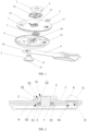
FIG. 1 is an exploded view of a cap assembly of a battery according to an embodiment of the present disclosure. -
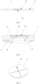
FIG. 2 is a cross-sectional view of the cap assembly of the battery according to an embodiment of the present disclosure. -
FIG. 3 is a cross-sectional view of a cap according to an embodiment of the present disclosure. -
FIG. 4 is an enlarged view of the A portion shown inFIG. 2 . -
FIG. 5 is a schematic structural view of a sealing pin according to an embodiment of the present disclosure. -
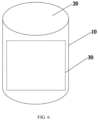
FIG. 6 is a schematic structural view of a cylindrical battery according to an embodiment of the present disclosure. - In the drawings:
1-cap; 11-liquid injection hole; 12-mounting hole; 13-groove portion; 2-pole; 21-first flange; 22-second flange; 3-terminal; 31-limiting groove; 32-positioning groove; 4-sealing pin; 41-notch; 42-recess; 5-upper plastic member; 51-protruding portion; 52-positioning protrusion; 6-lower plastic member; 61-avoidance hole; 62-avoidance groove; 7-sealing ring; 8- current collector; 81-through hole; 10-shell; 20-opening; 30-cell. - In the description of the present disclosure, unless specified and limited, otherwise, terms "mounted", "coupled", "connected" shall be interpreted broadly, such as fixed connection, detachable connection, or integrally connected; mechanical connection, electrical connection; direct connection, indirect connection via an intermediate medium, or communication between inner spaces of two elements. Any ordinary skilled person in the art shall understand a specific meaning of the above terms in the context of the present disclosure based on specific cases.
- In the present disclosure, unless specified and limited, otherwise, a first feature being "above" or "below" a second features may include that the first feature directly contacts with the second feature, and may also include that the first feature does not directly contact with the second feature but contacts with the second feature through additional feature between the first feature and the second feature. Moreover, the first feature being "above", "on", and "on top of' the second feature includes the first feature being directly above and diagonally above the second feature, or indicates that a horizontal height of the first feature is higher than a horizontal height of the second feature. The first feature being "below", "under", and "beneath" the second feature includes the first feature being directly below and diagonally below the second feature, or indicates that a horizontal height of the first feature is lower than a horizontal height of the second feature.
- In the description of the present disclosure, orientations or positional relationships indicated by terms "up", "down", "left", "right", etc. are based on the orientations or position relationships shown in the accompanying drawings, and are only for the convenience of describing the present disclosure and simplifying the description, rather than implying or indicating that the device or the component referred to must have a particular orientation or constructed and operated in a particular orientation, and thus these terms cannot be understood as limiting the present disclosure. In addition, terms "first" and "second" are only used for distinguishing in description and have no special meaning.
- In an embodiment of the present disclosure, a cap assembly of a battery, a cylindrical battery, and a battery pack are provided. As shown in
FIG. 6 , the battery pack includes a plurality of cylindrical batteries. The cylindrical battery includes acylindrical shell 10, acell 30, and a cap assembly. Anopening 20 is defined at one end face of theshell 10, and thecell 30 is able to be put or placed into theshell 10 from the opening. The cap assembly is configured to cover and seal the opening of thehousing 20. It should be noted that, in some embodiments, an inner side and an outer side are described with reference to the cylindrical battery. A side of the cap assembly facing an interior of theshell 10 is referred as the "inner side", and a side of the cap assembly facing an exterior of theshell 10 is referred as the "outer side". - As shown in
FIGS. 1 and 2 , the cap assembly of the battery includes acap 1, apole 2, and aterminal 3. Thecap 1 is arranged to block the opening at the end of the shell. Thepole 2 is disposed on a first side of thecap 1, and the first side of thecap 1 is the inner side of thecap 1. Thepole 2 is electrically connected to the cell inside the shell. Theterminal 3 is disposed on a second side of thecap 1, and the second side of thecap 1 is the outer side of thecap 1. Thepole 2 is further is electrically connected to theterminal 3. Theterminal 3 is arranged to be connected to an external load. In this way, it is possible to realize the electrical connection between the cell and the external load outside the cylindrical battery. In some embodiments, thecap 1 is in shape of substantially a circle. - Exemplarily, as shown in
FIGS. 1-3 , a mountinghole 12 is defined in thecap 1. The mountinghole 12 penetrates through thecap 1. The cap assembly of the battery further includes anupper plastic member 5, alower plastic member 6, and asealing ring 7. Theupper plastic member 5 is arranged on the outer side of thecap 1 and located between thecap 1 and theterminal 3. Thelower plastic member 6 is arranged on the inner side of thecap 1 and located between thepole 2 and thecap 1. The sealingring 7 is arranged in the mountinghole 12 and abuts against theupper plastic member 5 and thelower plastic member 6, respectively. Thepole 2 successively runs through thelower plastic member 6, the sealingring 7, and theupper plastic member 5, and is further connected to theterminal 3. The arrangement of theupper plastic member 5, the sealingring 7, and thelower plastic member 6 not only insulates thepole 2 from thecap 1, but also provides a sealing between thepole 2 and thecap 1. - Exemplarily, as shown in
FIG. 2 , a limitinggroove 31 is defined at a first end of theterminal 3 away from thecap 1. An end of thepole 2 is located on the inner side of thecap 1 and arranged with afirst flange 21. Asecond flange 22 is disposed at a second end of theterminal 3. Thefirst flange 21 abuts against thelower plastic member 6, and thesecond flange 22 is engaged in the limitinggroove 31. By using the cooperation between the first flange at one of two opposite ends of thepole 2 and thelower plastic member 6, and using the cooperation between the second flange at the other of two opposite ends of thepole 2 and the limitinggroove 31 defined in theterminal 3, respectively, the connection of thecap 1 assembly is more firmly. - Exemplarily, as shown in
FIG. 2 , one of a side wall of theupper plastic member 5 facing thecap 1 and a side wall of thecap 1 facing theupper plastic member 5 is arranged with a protrudingportion 51, and the other of the side wall of theupper plastic member 5 facing thecap 1 and the side wall of thecap 1 facing theupper plastic member 5 defines agroove portion 13. The protrudingportion 51 is engaged with thegroove portion 13. By the engagement of thegroove portion 13 with the protrudingportion 51, it is possible not only to position a position of theupper plastic member 5 relative to thecap 1, but also prevent theupper plastic member 5 from being twisted relative to thecap 1. In the present embodiment, as shown inFIGS. 2 and3 , the protrudingportion 51 is disposed on the side wall of theupper plastic member 5 facing thecap 1, and thegroove portion 13 is defined on the side wall of thecap 1 facing theupper plastic member 5. Exemplarily, as shown inFIGS. 1 and3 , thegroove portion 13 is arranged coaxially with the mountinghole 12, but thegroove portion 13 is a non-circular groove, thereby better preventing theupper plastic member 5 from being twisted relative to thecap 1. In other embodiments, the position of the protrudingportion 51 may be interchangeable with the position of thegroove portion 13. - Exemplarily, one of a side wall of the
upper plastic member 5 facing theterminal 3 and a side wall of theterminal 3 facing theupper plastic member 5 is arranged with apositioning protrusion 52, and the other of the side wall of theupper plastic member 5 facing theterminal 3 and the side wall of theterminal 3 facing theupper plastic member 5 defines apositioning groove 32. Thepositioning protrusion 52 is engaged with thepositioning groove 32, to achieve the positioning between the terminal 3 and theupper plastic member 5, and prevent the terminal 3 from being twisted relative to theupper plastic member 5. In the present embodiment, as shown inFIG. 2 , thepositioning protrusion 52 is disposed on the side wall of theupper plastic member 5 facing theterminal 3, and thepositioning groove 32 is defined on the side wall of theterminal 3 facing theupper plastic member 5. However, in other embodiments, the position of thepositioning protrusion 52 may be interchangeable with the position of thepositioning groove 32. Exemplarily, as shown inFIG. 1 , a plurality of positioningprotrusions 52 are arranged on theupper plastic member 5, and correspondingly, a plurality ofpositioning grooves 32 are defined on theterminal 3, thereby better preventing the terminal 3 from being twisted relative to theupper plastic member 5. - Exemplarily, as shown in
FIG. 2 , the sealingring 7 is a ring-shaped structure, and an outer contour of the sealingring 7 is step-shaped. An end of the sealingring 7 having a smaller outer contour extends into an end of the mountinghole 12 having a smaller diameter, and an end face at an end of the sealingring 7 having a larger outer contour is attached to the inner side of thecap 1, such that the sealingring 7 may wrap thecap 1, thereby ensuring a good sealing and insulation effect between thecap 1 and thepole 2. - Exemplarily, as shown in
FIGS. 1 and 2 , thelower plastic member 6 is circular and attached to the end face on the inner side of thecap 1. In the present embodiment, a size of thelower plastic member 6 is slightly less than that of thecap 1. In this way, on one hand, it is possible to ensure that thecap 1 is smoothly mounted on the shell, and on the other hand, it is also possible to provide a good insulation effect between thecap 1 and conductive components in the shell. Exemplarily, as shown inFIGS. 1 and 2 , a side of thelower plastic member 6 facing theend cover 1 defines anavoidance groove 62. The end of the sealingring 7 having a larger outer contour is accommodated in theavoidance groove 62, thereby ensuring thelower plastic member 6 being well attached to the inner side of thecap 1. - In the present embodiment, as shown in
FIG. 1 , the cap assembly further includes a current collector 8. A first end of the current collector 8 is electrically connected to the cell of the cylindrical battery, and a second end of the current collector 8 is electrically connected to thepole 2. Exemplarily, the first end of the current collector 8 is welded to the cell, and the second end of the current collector 8 defines a throughhole 81 and is sandwiched between thelower plastic member 6 and thepole 2. Thepole 2 runs through the throughhole 81 defined in the current collector 8, and the current collector 8 is sandwiched between thepole 2 and thelower plastic member 6, to realize the electrical connection between thepole 2 and the current collector 8. The structure is simple and easy to implement. - Exemplarily, as shown in
FIGS. 1, 2 and4 , thecap 1 defines aliquid injection hole 11. The cap assembly of the battery further includes asealing pin 4. The sealingpin 4 is able to seal theliquid injection hole 11. The sealingpin 4 has a thinning region having an explosion-proof function. It should be noted that, the thinning region refers to the region having a thickness thinner than a thickness of each portion of the rest region. When an internal pressure of the cylindrical battery is too high, the thinning region is firstly cracked, such that the pressure may be relieved, thereby avoiding the explosion of the cylindrical battery. - The cap assembly of the battery according to some embodiments, by setting the thinning area on the
sealing pin 4 configured to seal theliquid injection hole 11, the sealingpin 4 may have a function of an explosion-proof valve. On one hand, it's unnecessary to additionally arrange an explosion-proof valve on the cap assembly, which reduces the number of components, thereby reducing cost and improving a production efficiency of the cap assembly. On the other hand, it's unnecessary to additionally define the mountinghole 12 on thecap 1 to mount the explosion-proof valve, which can not only further improve the production efficiency of the cap assembly, but also leave a large arrangement space for theliquid injection hole 11 on thecap 1, such that theliquid injection hole 11 has a diameter large enough, thereby ensuring the stability of the liquid injection process. The cylindrical battery of the present embodiment, by arranging the cap assembly of the battery as described above, has a simple manufacturing process, a high production efficiency, and a low cost, and the liquid injection process has a good stability, thereby ensuring a good performance. The battery pack of the present embodiment, by setting the cylindrical battery as described above, has a high production efficiency, a low cost, and a good performance. - Exemplarily, the thickness of the thinning region is not more than (, i.e., less than or equal to) 0.2mm. When the thickness of the thinning region is within the above range, it may ensure that the thinning region will be cracked in time in response to the internal pressure of the cylindrical battery being greater than a safe range, and ensure the safety of the cylindrical battery. The above range of the thickness of the thinning region is only a preferable range and but is not a limitation to the range of the thickness of the thinning region. During the actual design, the thickness of the thinning region may also be set in combination with parameters such as a material of the sealing
pin 4, a preset safety pressure of the cylindrical battery, or the like, which is not specifically limited herein. - Exemplarily, as shown in
FIGS. 2 and4 , a position of thelower plastic member 6 facing or corresponding to theliquid injection hole 11 further defines anavoidance hole 61. Theavoidance hole 61 has a diameter not less than (i.e., greater than or equal to) the diameter of theliquid injection hole 11. The arrangement of theavoidance hole 61 may ensure that the electrolyte may flow smoothly into the cell when the liquid is injected into the cylindrical battery, thereby ensuring that the liquid injection process is smooth. - In the present embodiment, as shown in
FIGS. 4 and 5 , the sealingpin 4 defines anotch 41, and a position of the sealingpin 4 corresponding to thenotch 41 forms the thinning region. Defining thenotch 41 makes it easier to achieve the thinning of the sealingpin 4. In the present embodiment, thenotch 41 is defined on the outer side of the sealingpin 4, which is more convenient for processing. In other embodiments, thenotch 41 may also be defined on the inner side of the sealingpin 4. In some other embodiments, the thinning region on thesealing pin 4 may also be implemented as a recess and the like, which is not limited herein. - Exemplarily, as shown in
FIG. 5 , the sealingpin 4 defines twonotches 41, and the twonotches 41 are intersected with each other. An intersection of the twonotches 41 forms a continuous thinning region. When the internal pressure of the cylindrical battery is greater than a preset value, the intersection of the twonotches 41 is prone to be cracked first, and the crack gradually extends around the intersection along thenotches 41, to ensure the reliability of the explosion-proof structure. In other embodiments, the specific number and shapes of thenotches 41 are not limited herein, and may be selected as needed. - Exemplarily, as shown in
FIG. 4 , the sealingpin 4 further defines arecess 42. Therecess 42 is defined opposite to thenotch 41. Therecess 42 is located on one of the inner side and the outer side of the sealingpin 4 while thenotch 41 is located on the other of the inner side and the outer side of the sealingpin 4. Besides, therecess 42 is disposed directly opposite to thenotch 41. In the present embodiment, thenotch 41 is located on the outer side of the sealingpin 4, and therecess 42 is located on the inner side of the sealingpin 4. On one hand, defining therecess 42 is convenient to control the thickness of the thinning region in the range that is easy to break or crack; on the other hand, an edge region of the sealingpin 4 have a thickness great enough. In this way, it is possible to ensure that the sealingpin 4 has a sufficient area cooperating with theliquid injection hole 11, and ensure the good sealing effect of the sealingpin 4. - In the present embodiment, the sealing
pin 4 is connected to thecap 1 by welding, which is convenient to ensure a good sealing between the sealingpin 4 and thecap 1. For example, the welding may be laser welding. - Exemplarily, as shown in
FIG. 4 , theliquid injection hole 11 is a stepped hole. An end of the stepped hole having a greater diameter faces the outer side of thecap 1, and thesealing pin 4 is sealed to the end of the stepped hole having a greater diameter. An end face at an end of the stepped hole having a smaller diameter may limit a position of the sealingpin 4 in an axial direction, so as to ensure an accuracy of the position of the sealingpin 4. Exemplarily, as shown inFIG. 4 , an inner wall surface of the end of the stepped hole having a greater diameter is a tapered surface. From the outer side to the inner side, a diameter of the tapered surface gradually decreases. A peripheral wall surface of the sealingpin 4 is also a tapered surface. By arranging the wall surface of the stepped hole and the wall surface of the sealingpin 4 matched with and cooperated with each other as tapered surfaces, when placing the sealingpin 4 into the stepped hole from the outer side to the inner side, it may ensure that the peripheral wall surface of the sealingpin 4 is in full contact with the inner wall surface of the stepped hole, thereby further improving the sealing effect of the sealingpin 4.
Claims (16)
- A cap assembly of a battery, comprising:a cap (1), defining a liquid injection hole (11);a pole (2), disposed on a first side of the cap (1);a terminal (3), disposed on a second side of the cap (1) and electrically connected to the pole (2), wherein the second side of the cap (1) is opposite to the first side of the cap (1); anda sealing pin (4), configured to seal the liquid injection hole (11), and having a thinning region configured for an explosion-proof function.
- The cap assembly of the battery as claimed in claim 1, wherein a thickness of the thinning region is less than or equal to 0.2mm.
- The cap assembly of the battery as claimed in claim 1, wherein the sealing pin (4) defines a notch (41), and a position of the sealing pin (4) corresponding to the notch (41) forms the thinning region.
- The cap assembly of the battery as claimed in claim 1, wherein the sealing pin (4) defines two notches (41), and the two notches (41) are intersected with each other.
- The cap assembly of the battery as claimed in claim 3, wherein the sealing pin (4) further defines a recess (42), the recess (42) is located at one of two opposite sides of the sealing pin (4), the notch (41) is located at the other of two opposite sides of the sealing pin (4), and the recess (42) is disposed directly opposite to the notch (41).
- The cap assembly of the battery as claimed in claim 1, wherein the liquid injection hole (11) is a stepped hole, one end of the stepped hole having a greater diameter faces the second side of the cap (1), and the sealing pin (4) is sealed to the end of the stepped hole having a greater diameter.
- The cap assembly of the battery as claimed in claim 6, wherein an inner wall surface at the end of the stepped hole having a greater diameter is a tapered surface, a diameter of the tapered surface gradually decreases along a direction from the second side of the cap (1) to the first side of the cap (1), and a peripheral wall surface of the sealing pin (4) is a tapered face.
- The cap assembly of the battery as claimed in claim 1, wherein the sealing pin (4) is welded to a hole wall of the liquid injection hole (11).
- The cap assembly of the battery as claimed in any one of claims 1-8, wherein the cap (1) defines a mounting hole (12), and the cap assembly of the battery further comprises:an upper plastic member (5), disposed between the cap (1) and the terminal (3);a lower plastic member (6), disposed between the pole (2) and the cap (1); anda sealing ring (7), disposed in the mounting hole (12) and abutting against both the upper plastic member (5) and the lower plastic member (6), wherein the pole (2) successively runs through the lower plastic member (6), the sealing ring (7), and the upper plastic member (5), and is further connected to the terminal (3).
- The cap assembly of the battery as claimed in claim 9, wherein the lower plastic member (6) defines an avoidance hole (61) at a position opposite to the liquid injection hole (11), and the avoidance hole (61) has a diameter less than or equal to that of the liquid injection hole (11).
- The cap assembly of the battery as claimed in claim 9, wherein the terminal (3) defines a limiting groove (31) at one end away from the cap (1), a first end of the pole (2) close to the first side of the cap (1) is arranged with a first flange (21), a second end of the pole (2) close to the second side of the cap (1) is arranged with a second flange (22), the first flange (21) abuts against the lower plastic member (6), and the second flange (22) is engaged into the limiting groove (31).
- The cap assembly of the battery as claimed in claim 9, wherein one of a side wall of the upper plastic member (5) facing the terminal (3) and a side wall of the terminal (3) facing the upper plastic member (5) is arranged with a positioning protrusion (52), the other of the side wall of the upper plastic member (5) facing the terminal (3) and the side wall of the terminal (3) facing the upper plastic member (5) defines a positioning groove (32), and the positioning protrusion (52) is engaged with the positioning groove (32).
- The cap assembly of the battery as claimed in claim 9, wherein one of a side wall of the upper plastic member (5) facing the cap (1) and a side wall of the cap (1) facing the upper plastic member (5) is arranged with a protruding portion (51), the other of the side wall of the upper plastic member (5) facing the cap (1) and the side wall of the cap (1) facing the upper plastic member (5) defines a groove portion (13), and the protruding portion (51) is engaged with the groove portion (13).
- The cap assembly of the battery as claimed in claim 9, further comprising a current collector (8), wherein a first end of the current collector (8) is arranged to be connected to a cell, and a second end of the current collector (8) is electrically connected to the pole (2);
the second end of the current collector (8) is sandwiched between the lower plastic member (6) and the pole (2) and defines a through hole (81), and the pole (2) runs through the through hole (81). - A cylindrical battery, comprising:a cylindrical shell, defining an opening; andthe cap assembly as claimed in any one of claims 1-14, wherein the cap assembly is configured to cover and seal the opening.
- A battery pack, comprising a plurality of cylindrical batteries as claimed in claim 15.
Applications Claiming Priority (2)
| Application Number | Priority Date | Filing Date | Title |
|---|---|---|---|
| CN202220271644.4U CN217158535U (en) | 2022-02-10 | 2022-02-10 | Cover plate assembly of battery, cylindrical battery and battery pack |
| PCT/CN2022/128514 WO2023151320A1 (en) | 2022-02-10 | 2022-10-31 | Battery cover plate assembly, cylindrical battery, and battery pack |
Publications (2)
| Publication Number | Publication Date |
|---|---|
| EP4254632A1 true EP4254632A1 (en) | 2023-10-04 |
| EP4254632A4 EP4254632A4 (en) | 2024-10-16 |
Family
ID=82691179
Family Applications (1)
| Application Number | Title | Priority Date | Filing Date |
|---|---|---|---|
| EP22817059.3A Pending EP4254632A4 (en) | 2022-02-10 | 2022-10-31 | BATTERY COVER PLATE ASSEMBLY, CYLINDRICAL BATTERY AND BATTERY PACK |
Country Status (4)
| Country | Link |
|---|---|
| US (1) | US20230253649A1 (en) |
| EP (1) | EP4254632A4 (en) |
| CN (1) | CN217158535U (en) |
| WO (1) | WO2023151320A1 (en) |
Families Citing this family (25)
| Publication number | Priority date | Publication date | Assignee | Title |
|---|---|---|---|---|
| CN217158535U (en) * | 2022-02-10 | 2022-08-09 | 湖北亿纬动力有限公司 | Cover plate assembly of battery, cylindrical battery and battery pack |
| CN218299993U (en) * | 2022-08-17 | 2023-01-13 | 湖北亿纬动力有限公司 | Top cover assembly and battery structure |
| CN115275502A (en) * | 2022-08-31 | 2022-11-01 | 宁德新能源科技有限公司 | Electrochemical device and electric equipment |
| CN116169421B (en) * | 2022-09-09 | 2025-03-04 | 湖北亿纬动力有限公司 | Battery and assembly method thereof |
| CN218300133U (en) * | 2022-09-09 | 2023-01-13 | 湖北亿纬动力有限公司 | Current collecting disc, battery cover plate and battery structure |
| CN219180738U (en) * | 2022-09-20 | 2023-06-13 | 江苏正力新能电池技术有限公司 | A current collecting member and a secondary battery |
| CN115863936B (en) * | 2022-12-26 | 2025-02-11 | 湖北亿纬动力有限公司 | Battery |
| CN115863900B (en) * | 2022-12-26 | 2025-02-11 | 湖北亿纬动力有限公司 | Battery |
| WO2024169140A1 (en) * | 2023-02-13 | 2024-08-22 | 湖北亿纬动力有限公司 | Battery and battery pack |
| CN115911691B (en) * | 2023-03-14 | 2023-05-26 | 广汽埃安新能源汽车股份有限公司 | Top cap subassembly, battery monomer and power battery package |
| CN116845441B (en) * | 2023-07-03 | 2025-04-22 | 蜂巢能源科技股份有限公司 | Batteries and battery packs |
| CN117096512A (en) * | 2023-08-31 | 2023-11-21 | 力神(青岛)新能源有限公司 | Battery cover and manufacturing method and battery |
| CN220984808U (en) * | 2023-09-01 | 2024-05-17 | 上海兰钧新能源科技有限公司 | Top cover assembly, battery cells and battery packs |
| CN119609558B (en) * | 2023-09-12 | 2025-11-28 | 宁德时代新能源科技股份有限公司 | Repair welding tool, repair welding method and repair welding device |
| CN116937026B (en) * | 2023-09-15 | 2023-12-29 | 厦门海辰储能科技股份有限公司 | Lower plastic, top cover assembly and battery |
| CN221176411U (en) * | 2023-09-28 | 2024-06-18 | 比亚迪股份有限公司 | Battery shell, battery and electric equipment |
| CN117219933B (en) | 2023-11-07 | 2024-03-08 | 深圳海辰储能科技有限公司 | A top cover assembly, secondary battery, battery module and electrical equipment |
| CN117374491B (en) * | 2023-12-07 | 2024-02-20 | 蜂巢能源科技股份有限公司 | Batteries and electrical equipment |
| CN222051925U (en) * | 2023-12-25 | 2024-11-22 | 深圳市科达利实业股份有限公司 | Cover structure and battery |
| KR20250177931A (en) * | 2024-06-18 | 2025-12-26 | 삼성에스디아이 주식회사 | Secondary battery |
| CN222940138U (en) * | 2024-06-29 | 2025-06-03 | 惠州亿纬动力电池有限公司 | Top cap subassembly, battery cell and battery package |
| WO2026031900A1 (en) * | 2024-08-08 | 2026-02-12 | 厦门海辰储能科技股份有限公司 | End cover assembly, energy storage apparatus and electric device |
| CN118645774B (en) * | 2024-08-09 | 2024-10-25 | 蜂巢能源科技股份有限公司 | Battery cell cover plate assembly, battery cell and power device |
| CN119650808A (en) * | 2024-12-05 | 2025-03-18 | 江苏睿恩新能源科技有限公司 | A cylindrical lithium battery |
| CN120772725B (en) * | 2025-09-02 | 2026-01-13 | 宁德时代新能源科技股份有限公司 | Pre-welding equipment and control methods |
Family Cites Families (15)
| Publication number | Priority date | Publication date | Assignee | Title |
|---|---|---|---|---|
| KR100449763B1 (en) * | 2002-09-11 | 2004-09-22 | 삼성에스디아이 주식회사 | Cap assembly and secondary battery applying the same |
| US8945759B2 (en) * | 2010-10-22 | 2015-02-03 | Samsung Sdi Co., Ltd. | Rechargeable battery |
| CN104466077A (en) * | 2014-12-16 | 2015-03-25 | 天津神鹿能源有限公司 | Liquid injection explosion-proof pole structure of cylindrical power battery |
| CN205645552U (en) * | 2015-12-21 | 2016-10-12 | 上海奥威科技开发有限公司 | Novel explosion -proof valve structure of integration ultracapacitor system |
| CN205211804U (en) * | 2015-12-25 | 2016-05-04 | 湖北金泉新材料有限责任公司 | Battery sealing device |
| KR102337492B1 (en) * | 2017-04-07 | 2021-12-09 | 삼성에스디아이 주식회사 | Secondary battery |
| CN208580801U (en) * | 2018-08-08 | 2019-03-05 | 力信(江苏)能源科技有限责任公司 | A kind of lithium battery cover plate electrolyte replenishing structure, lithium battery cover plate |
| DE102019134427A1 (en) * | 2019-12-16 | 2021-06-17 | Bayerische Motoren Werke Aktiengesellschaft | Lithium-ion battery with extended service life |
| CN111933833B (en) * | 2020-09-21 | 2021-01-01 | 江苏时代新能源科技有限公司 | End cover assembly, battery monomer, battery and power consumption device |
| CN213520130U (en) * | 2020-12-04 | 2021-06-22 | 珠海冠宇电池股份有限公司 | Button battery and electronic equipment |
| CN215418489U (en) * | 2021-06-21 | 2022-01-04 | 东莞锂微电子科技有限公司 | Steel shell button cell with double explosion-proof structure |
| CN215451578U (en) * | 2021-06-30 | 2022-01-07 | 比亚迪股份有限公司 | a battery |
| CN215342748U (en) * | 2021-07-16 | 2021-12-28 | 厦门海辰新能源科技有限公司 | Utmost point post subassembly, battery top cap and power battery |
| CN215816069U (en) * | 2021-09-23 | 2022-02-11 | 厦门海辰新能源科技有限公司 | A top cap subassembly, battery and energy memory for battery |
| CN217158535U (en) * | 2022-02-10 | 2022-08-09 | 湖北亿纬动力有限公司 | Cover plate assembly of battery, cylindrical battery and battery pack |
-
2022
- 2022-02-10 CN CN202220271644.4U patent/CN217158535U/en active Active
- 2022-10-31 EP EP22817059.3A patent/EP4254632A4/en active Pending
- 2022-10-31 WO PCT/CN2022/128514 patent/WO2023151320A1/en not_active Ceased
- 2022-12-19 US US18/084,493 patent/US20230253649A1/en active Pending
Also Published As
| Publication number | Publication date |
|---|---|
| CN217158535U (en) | 2022-08-09 |
| US20230253649A1 (en) | 2023-08-10 |
| EP4254632A4 (en) | 2024-10-16 |
| WO2023151320A1 (en) | 2023-08-17 |
Similar Documents
| Publication | Publication Date | Title |
|---|---|---|
| US20230253649A1 (en) | Cap assembly of battery, cylindrical battery, and battery pack | |
| US20240429511A1 (en) | Housing assembly of button cell, button cell and electronic product | |
| CN115939611B (en) | End cover assembly, energy storage device and electric equipment | |
| EP4156386B1 (en) | Button cell and electronic device | |
| CN110752324A (en) | Sealing assembly and lithium ion battery | |
| EP4084195A1 (en) | Top cover for power battery, and power battery | |
| US12119503B2 (en) | Cap assembly and secondary battery | |
| EP4568004A1 (en) | Power battery cover and power battery | |
| US20240195029A1 (en) | Power battery cover and power battery | |
| EP4571996A1 (en) | Post terminal, top cover structure, battery, battery module and battery pack | |
| KR100525533B1 (en) | Explosion-proof valve group and hermetically closed secondary battery made by using the same | |
| EP4513640A1 (en) | Top cover assembly and battery | |
| CN222146502U (en) | Conductive column, cover plate assembly, battery device and electric equipment | |
| CN216054850U (en) | Lithium ion battery | |
| CN221102246U (en) | Cover plate of cylindrical battery and cylindrical battery | |
| CN118899600A (en) | A cover plate assembly and cylindrical lithium battery | |
| KR100238937B1 (en) | Thin type battery | |
| CN222654110U (en) | Cover plate assembly of battery unit, battery assembly and power utilization device | |
| CN222146408U (en) | Pole assembly, battery module, battery pack and power supply equipment | |
| US20250132429A1 (en) | Battery with no roll groove | |
| CN223401744U (en) | Battery cover and battery | |
| CN223427593U (en) | Top cover assembly, battery cells and battery packs | |
| CN223665481U (en) | Batteries and electrical devices | |
| CN223514072U (en) | The casing of the battery cell and the battery cell containing it | |
| CN224036480U (en) | Top cover structure for battery, battery and vehicle |
Legal Events
| Date | Code | Title | Description |
|---|---|---|---|
| STAA | Information on the status of an ep patent application or granted ep patent |
Free format text: STATUS: UNKNOWN |
|
| STAA | Information on the status of an ep patent application or granted ep patent |
Free format text: STATUS: THE INTERNATIONAL PUBLICATION HAS BEEN MADE |
|
| PUAI | Public reference made under article 153(3) epc to a published international application that has entered the european phase |
Free format text: ORIGINAL CODE: 0009012 |
|
| STAA | Information on the status of an ep patent application or granted ep patent |
Free format text: STATUS: REQUEST FOR EXAMINATION WAS MADE |
|
| 17P | Request for examination filed |
Effective date: 20221212 |
|
| AK | Designated contracting states |
Kind code of ref document: A1 Designated state(s): AL AT BE BG CH CY CZ DE DK EE ES FI FR GB GR HR HU IE IS IT LI LT LU LV MC ME MK MT NL NO PL PT RO RS SE SI SK SM TR |
|
| A4 | Supplementary search report drawn up and despatched |
Effective date: 20240918 |
|
| RIC1 | Information provided on ipc code assigned before grant |
Ipc: H01M 50/627 20210101ALI20240912BHEP Ipc: H01M 50/186 20210101ALI20240912BHEP Ipc: H01M 50/184 20210101ALI20240912BHEP Ipc: H01M 50/152 20210101ALI20240912BHEP Ipc: H01M 50/645 20210101ALI20240912BHEP Ipc: H01M 50/342 20210101AFI20240912BHEP |
|
| DAV | Request for validation of the european patent (deleted) | ||
| DAX | Request for extension of the european patent (deleted) |